1
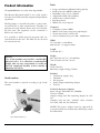
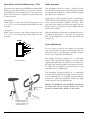
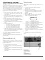
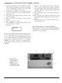
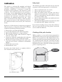
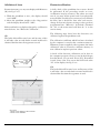
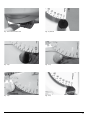
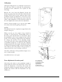
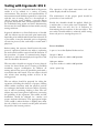
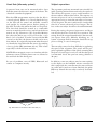
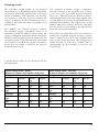
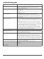
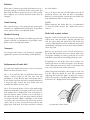
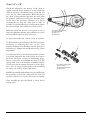
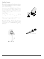
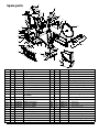
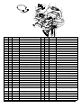
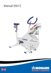
Manual 839 E
Important
Read the manual carefully before using the cycle
and save it for future use.
Contents
Monark Exercise AB ������������������������������������������������������������� 4
Product Information ������������������������������������������������������������� 5
Serial number���������������������������������������������������������������������������������� 5
Facts����������������������������������������������������������������������������������������������� 5
Operating Instruction ����������������������������������������������������������� 6
Power on crank or flywheel������������������������������������������������������������� 6
Operation of the ergometer������������������������������������������������������������� 6
Measured quantities������������������������������������������������������������������������ 6
Rpm Meter and visual Metronome / Puls���������������������������������������� 7
Initial operation�������������������������������������������������������������������������������� 7
Cycle adjustments��������������������������������������������������������������������������� 7
Connection to controller ������������������������������������������������������ 8
Setting of command type (PC or ECG device)�������������������������������� 8
What command type is set?������������������������������������������������������������ 8
Setting of terminal��������������������������������������������������������������������������� 8
Connection to PC���������������������������������������������������������������������������� 9
Connection to an external ECG device, digitally controlled���������� 10
Analogue control����������������������������������������������������������������������������11
Printer���������������������������������������������������������������������������������������������11
Calibration ��������������������������������������������������������������������������� 12
Daily check������������������������������������������������������������������������������������ 12
Checking of the pulse function������������������������������������������������������ 12
Validation of force�������������������������������������������������������������������������� 13
Electronic calibration��������������������������������������������������������������������� 13
Electronic calibration - terminal����������������������������������������������������� 14
Electronic calibration - PC������������������������������������������������������������� 14
Electronic calibration - with the pendulum������������������������������������� 14
Calibration������������������������������������������������������������������������������������� 16
Zero adjustment of meter panel���������������������������������������������������� 16
Testing with Ergomedic 839 E ������������������������������������������� 17
Heart rate (telemetry system)�������������������������������������������������������� 18
Subject supervision����������������������������������������������������������������������� 18
Reviewing results�������������������������������������������������������������������������� 19
Troubleshooting guide ������������������������������������������������������ 20
Operation interferences����������������������������������������������������������������� 21
Where to obtain additional information ��������������������������� 22
Service ��������������������������������������������������������������������������������� 24
Warning����������������������������������������������������������������������������������������� 24
Warranty���������������������������������������������������������������������������������������� 24
Service check and maintenance��������������������������������������������������� 24
Batteries���������������������������������������������������������������������������������������� 25
Crank bearing�������������������������������������������������������������������������������� 25
Flywheel bearing��������������������������������������������������������������������������� 25
Transport��������������������������������������������������������������������������������������� 25
Replacement of brake belt������������������������������������������������������������ 25
Brake belt contact surface������������������������������������������������������������� 25
Chain 1/2“ x 1/8“���������������������������������������������������������������������������� 26
Freewheel sprocket����������������������������������������������������������������������� 27
Spare parts �������������������������������������������������������������������������� 28
MONARK EXERCISE AB, Vansbro, Sweden
Monark Exercise AB
Monark has 100 years’ experience of bicycle production. The Monark tradition has yielded
know-how, experience, and a real feel for the product and quality. Since the early 1900s,
Monark’s cycles have been living proof of precision, reliability, strength and service. That are
the reasons why we are now the world leader in cycle ergometers and the market leader in
Scandinavia in transport cycles.
We manufacture, develop and market ergometers and exercise bikes, transport bikes and
specialized bicycles. Our largest customer groups are within health care, sports medicine,
public authorities, industry and postal services.
For more information: http://www.monarkexercise.se
4
Monark 839 E
Product Information
Facts
Congratulations on your new ergometer.
•
•
•
•
•
•
•
The Monark Ergomedic 839 E is one of the world's
most precise and user-friendly computerized pendulum
ergometers.
The Ergometer is controlled by either a control unit,
an external PC or other external units. The bike can
perform max and submax fitness tests and calculate
the VO2 max. The ergometer can be connected to
ECG to do work tests.
It is possible to build personal programs that are
custom made for the user. The bike can also be used
for normal exercise.
Large, well-balanced flywheel 20 kg (48 lbs)
Brake power 0-1400W at 200 rpm
Pendulum scale, easy to calibrate
Adjustable saddle and handlebar
Stable frame, solid steel tube.
Powder painted
Wheels for easy transport
Computer
• Computer system 8 MHz
• Multi-colour rpm pacing bar graph display
• Visual metronome or heart rate
• Serial communication port: 300 - 38400 baud
Width
517 mm (20”) at handlebar
640 mm (25”) at support tubes
Length
1150 mm (45”)
NOTE!
Use of the product may involve considerable
physical stress. It is therefore recommended
people who are not accustomed to cardio or
not feel completely healthy to first consult a
physician for advice.
Serial number
The serial number is placed according to fig: Serial
number.
1
Height
945-1295 mm (37-51”) at handlebar
790-1110 mm (31-44”) at seat
Weight
56 kg (128 lbs)
Max user weight 250 kg (550 lbs)
Included
• Calibration weight, 4 kg
• Chestbelt
• PC-program
• Power adaptor/switching adaptor
• Tool kit
Technical data power adaptor
Input voltage: 220-240V AC, 50/60Hz.
Current: 650mA
Output voltage: 24V DC switching adapter alt. 18V
AC.
(Sweden, 18V, Art. No: 9339-67, other countries
incl. USA, 24V, Art. No: 9339-66)
NOTE! The power adaptor must be approved by
your national electrical authorities. In Europe, it must
be CE marked.
Fig: Serial number (1)
Monark 839 E
5
Operating Instruction
Here are instructions for connections and opportunities
for connection to external communication. The need
for advanced technical documentation / protocols
for systems building, contact Monark Exercise AB,
Sweden.
Power on crank or flywheel
When the Ergomedic 839 Medical is adapted to
ECG work tests it is set to measure the power on the
crank.
When the Ergomedic 839 E is adapted to fitness tests
it is set to measure the power on the flywheel.
A sticker, placed on the display, see fig: ECG-sticker,
informs that the ergometer is set to measure the power
on the crank.
For information about how respective control units
works, see respective sections.
The Monark Ergometer 839 E can be controlled
externally from a terminal, a PC or an ECG device.
Direct printer connection port.
The control is performed over a serial line using ANSI/
ISO/ASCII format commands. The interface is a 9-pin
male D-sub connector, compatible with the RS232
standard, located on the front of the main unit.
It is also possible to use an analogue control from any
external source to set the workload. This is done by
the contacts b32 och z32 on the main connector on
the bike.
The ergometer need not to be turned off prior to
connection of the external components, although
removing the power from all devices may prevent
erroneous data transfer between equipment during
interconnection. Caution must be exercised in the
connection of various types of equipment from
different manufactures to avoid electrical hazards and
physical damage. The user must be certain that the
instrument connector and the cable are designed for
the intended purpose. Serious injury to the user and /
or equipment may result if inappropriate connections
are attempted.
Fig: ECG-sticket
Operation of the ergometer
Measured quantities
The Ergomedic 839 E is built on a stabile frame, a large
well balanced flywheel, a break belt and a pendulum
weight which measures the force. Pedals and a chain
drive are provided to spin the flywheel as a tension
device tightens the belt to regulate the braking force
applied to the wheel. The pendulum indicates the
applied force directly on the scale located on the right
side of the flywheel.
The computer system consists of one main unit and
one control unit (terminal, PC or ECG). The main
unit reads in the pedal speed, the applied force
and determines the subjects heart rate by a chest
transmitter. Additionally, the base controll activates
the motor to adjust the tension of the belt, thereby
regulating the applied braking force. The force may
6
be automatically varied in response to changes in
pedal speed to maintain a constant power workload.
Spacer
Energy
Heart rate
meter, miles
kcal
bpm
Force
Power
Newton (N), kp
Watts (W), kpm/min or
VO2 ml/min/kg
min:sec
kilogram (kg), pounds (lb)
Time
Weight
Monark 839 E
Rpm Meter and visual Metronome / Puls
Initial operation
The metronome (the two green LED bars in the middle)
flashes once per pedal stroke at a preset rate. The two
green LED bars in the middle can also be set to show
pulse. Pedal frequency compared to metronome rate
is always shown.
The ergometer 839 E is to 100 % calibrated at the
factory. The user may wish to verify this by performing
the mechanical calibration of the pendulum weight.
See ”Electronic calibration”.
Underspeed:
Pedal speed is lower than desired metronome rate
2, 4, 8, 16 or more depending which LED bar that
indicates.
Overspeed:
Pedal speed is greater than desired metronome rate
2, 4, 8, 16 or more depending which LED bar that
indicates.
RPM
16
8
Do not forget to remove the transport protections
(the transportation bracket on the weight lever, the
protection tape on the flywheel and the transport
blocks above and below the flywheel).
Metro/Puls
16
8
Perform the electrical calibration as specified in section
"Calibration Electronics”. Test ride the ergometer.
The 839 E Ergometer is now fully functional and
ready to use.
Cycle adjustments
42
4
Apply power to the ergometer by first connecting the
cable from the power adaptor to the ergometer at the
front connector labelled "24VDC / 18VAC". Then
plug the power adaptor into the wall outlet. Turn the
power switch to on position. A green LED indicates
power to the 839 E.
2
Seat height should be adjusted to a comfortable
position. The appropriate height is to have the knee
slightly bent when the sole of the foot is centred over
the pedal axle with the pedal to the bottom position.
To adjust the seat height loosen the lever(1) on the
seat tube. See Fig: Adjustments.
Fig: RPM display
The handlebar setting should be in a comfortable
position when cycling. During longer exercise sessions
it is recommended to occasionally change handlebar
position. To adjust the handlebar, loosen the quick
release lever(2). See Fig: Adjustments.
2
min. 8 cm
(3”)
NOTE! The handlebar stem should be inserted into
the frame tube at least 3 inches (about 8 cm). This
measure is marked with “MAX” on the stem(3).
3
1
Fig: Adjustments
1) Quick release bolt
2) Quick release lever
3) Inserted min. 3”
Monark 839 E
7
Connection to controller
Setting of terminal
Setting of command type (PC or ECG device) When using a terminal (Art. No: 9339-51) do as
From software version R15
First check the brake belt tension. If the belt is too
tight loosen it a little by moving the pendulum to
about 4 kp and hold it there for a few seconds. Then
the force-adjusting servo will loosen the belt tension.
To be sure that pendulum positions are correct, do a
calibration. See ”Electronic calibration”.
1. Press the switch to turn off the power, see fig:
Connections. Disconnect the cable from any
connected device.
2. Adjust the scale mechanically so that 0-index on
the scale and the mark on the pendulum are in
line.
3. Move the pendulum to 6 kp and hold it there.
4. Turn on the power again. The green LED (3) lights
when power is connected to the bike.
5. Hold the pendulum at 6 kp until two beeps are
heard.
6. Move the pendulum to:
0 = mode for use with PC or hand unit.
1 = mode for Siemens Megacart ECG.
2 = mode for other ECG devices, alt 1.
3 = mode for other ECG devices, alt 2.
7. Hold the selected position until two beeps are
heard. Then release the pendulum to 0. The system
will now restart in the seleted mode.
Alt. 1: ECG, Ergoline compatible command set,
requested load value.
Alt. 2: ECG, Ergoline compatible command set, current load value.
follows:
1. Connect the terminal to the bike using the
enclosed cable.
2. Connect power to the bike.
3. When the main menu is displayed on the LCDscreen press ‘99’ and the hidden service menu
appears.
4. Press ‘6’, ”Settings”.
5. Press ‘ENTER’ (normally 13 times) until the
display ”Command type” appears.
- 0 Terminal/PC
-1-3 see manual
- (0) _
a) Press ‘1’ and ‘ENTER’ if the bike is
connected to a Siemens Megacart ECG device.
b) Press ‘2’ and ‘Enter’ if the bike is
connected to other ECG device with an Ergoline
protocol for communication, alt. 1.
c) Press ‘3’ and ‘ENTER’ if the bike is
connected to other ECG device with an Ergoline
protocol for communication, alt. 2.
d) Press ‘0’ if the bike is connected to a terminal
or PC.
6. After that press ‘0’ twice to go back to main
menu.
2
3
4
5
What command type is set?
When the power is turned on a beep is heard and
depending on the beeps number you can decide which
command type is set.
• Commando type 0: One long beep.
• Commando type 1: A long beep followed by a
short beep.
• Commando type 2: A long beep followed by two
short beeps.
• Commando type 3: A long beep followed by three
short beeps.
8
6
1
Fig: Connection
1) Printer connection
2) Power switch
3) Power connection
4) LED
5) Chassis ground
6) Terminal/PC (serial)
7) Analogue connection
Monark 839 E
7
Connection to PC
In terminal mode do the following settings:
- 9600 baud
- 8 data bit
- 1 stop bit
- no parity
- no flow control
- set terminal emulation to VT100
- set the COM port number. A USB serial converter is automatically
assigned to a COM port number by Windows.
This number is indicated under Startmenu /
Settings / Control Panel / System Hardware.
To connect a PC to the ergometer, use a 0-modem
cable (RS232) with a 9-pin D-sub female at each end.
If no RS232 serial port is available on the PC use a
USB serial adaptor to connect to an USB port.
Follow these steps to install the USB adaptor drivers:
1. Locate the USB adaptor.
2. Inside the USB adaptor packaging, there is a miniCD.
3. Insert the mini-CD into the CD-ROM drive and
install the driver software. If there is no CD drive
on your computer, driver software is available for
down from the website (http://www.vscom.de/
USB-CD).
4. Finalize the driver software installation by
inserting the USB adaptor.
5. Install the Monark Software disk.
6. Connect the USB Adapter to the Serial Cable and
proceed with testing.
To control the ergometer use the PC software supplied
with the ergometer and which is common to the
models 831 E och 939 E, or other PC software made
for the Ergomedic 839 E.
From software version MEC3V11R14 and later
settings can be made from a PC in terminal mode
if the terminal is not available. Set PC in terminal
mode. A terminal emulator is normally available in
i.e. Windows under Accessories/Communication.
Connect Ergometer and PC with the 0-modem cable
(normally used for the ergometer terminal).
Turn on power to the ergometer. The ergometer is
now checking what type of device is connected. When
finished a message appears on the PC screen.
Common commands:
• Calibration: Type: cali[enter] and follow the
instructions on the screen.
• Setting to control ergometer from other external
ECG devices: Siemens Megacart ECG device:
Type: env cmdtype=1[enter]
• Setting to control ergometer from external ECG
devices: Various ECG devices: (most common
setting) type: env cmdtype=2[enter]
To go back to control the ergometer with the terminal
type: env cmdtype=[enter]
A lot of other settings can be made. For more
information about this please see Technical Reference
Manual MEC3V11Rn.
Monark 839 E
9
Connection to an external ECG device, digitally controlled
(if terminal is used)
1. Connect the terminal via the supplied 0-modem
cable (9-pol. D-sub female connector on each end)
to the corresponding connector (5) in the front
end of the cycle, see Fig: Connections.
2. Connect the net adaptor to a suitable wall outlet
and to the connection (3) on the bike and then
turn power on.
3. After a short while the main menu is shown on the
terminal's display.
4. Press '99' and the service menu comes up on the
display.
5. Press ‘6’, for Service set-up.
6. Press ‘Enter’ on the following settings until
“Command type” is shown.
7. This says:
- 0 Terminal/PC
-1-3 see manual
- (0) _
8. Return to main menu by pressing '0' and then
press '0' again to finish. The computer will then
save the settings in the memory before it turns off.
Computer will start up again automatically after
a few seconds.
9. Turn off the power and remove the terminal incl.
the cable.
10.Use a suitable cable between an ECG device and
the bike (ECG Siemens Megacart requires a special
cable).
11.The bike can now be controlled only from an
external ECG device.
Reset the Ergometer to use with terminal/PC.
Follow steps 1-7. At step 7 press ‘0’ and then ‘Enter’.
The ergometer can now be controlled again from the
terminal or an external PC.
If a zero (0) is displayed at the 3rd line, the ergometer
is in normal mode which means that the bike can
not be controlled by an external ECG device. Press
'1' if a Siemens Megacart with Ergomed 940 will be
used. For use of other devices press '2' or '3' and then
‘ENTER’ (see section "Setting of command type").
Is the desired settings already in parenthesis press
‘Enter’.
2
3
4
5
1
6
Fig: Connection
1) Printer connection
2) Power switch
3) Power connection
4) LED
5) Chassis ground
6) Terminal/PC (serial)
7) Analogue connection
10
7
Monark 839 E
Analogue control
Printer
The workload of the Ergometer can be controlled
by external devices such as an analog ECG device
(must be between 2 and 4 volts to operate properly).
For settings, see the manual for the terminal and the
manual for the software.
A parallel interfaced printer may be attached to
provide written reports.
Start by connecting the printer to the parallel output
(1) located on the front of the bike. The terminal or
the computer attaches both via a serial cable to the
9-pin interface connector (5) located on the front of
the ergometer, see Fig: Connections.
If the external device is a desktop printer it must be
capable of emulating Epson alt. IBM Proprinter mode
to operate. Verify that the System set-up have been set
to enable automatic printout. If it has been disabled,
no output will reach the device until it has been
enabled. Also, the baud rate, 4800 baud, selected by
the interface cable must match that of the device.
Paper must be in the printer and the choice of units
must be made before the printer is in use (see user
manual for the printer).
The automatic printout length is a pre-set to eleven inch
pages for standard fanfold or zee-fold paper. At the
top of the each page, a header designating the columns
is printed. The time period between the printing of
each line may be set as desire, from 0 (continuous
output) to 255 seconds in one second increments.
The standard setting is 15 seconds between printouts.
This provides reasonable documentation while not
wasting large quantities of paper.
Monark 839 E
11
Calibration
Daily check
The 839 E is a mechanically weighted and braked
ergometer, making performance validation a simple
procedure. Calibration is necessary to match the
mechanics of the ergometer to the electronics of the
computer. The work performed on the ergometer is
the product of the weight lifted times the numbers
of revolutions (factored). Validation includes both
mechanical and electronic procedures. For more
information, see Manual terminal (art. No: 7950302) or the manual of the software. If the ergometer
fails to pass any section of the validation, proceed to
the calibration and/or service menu (‘99’ in the main
menu).
The following procedure will assure the user that the
ergometer is performing properly on a daily basis.
Inspection of all mechanical components is suggested
after any repair, or component service. The following
validation should be performed annually:
If you found something strange at the daily validation
that you cannot fix by your own, please contact the
service at Monark Exercise.
1. Remove the cover from the flywheel.
2. Loosen the brake belt at the balancing spring.
3. Wait until the flywheel is no longer moving.
4. The pendulum weight index should be aligned
with “0“ on the scale.
5. Attach the calibration weight where the balancing
spring was placed, see fig: Calibration weight
6. The known weight should match the value on the
scale. If not see section “Calibration of Pendulum
Weight “.
7. Reattach the tension belt.
8. Reassemble the cover.
• Check of pulse function, see section.
• Check of work load, see section.
• Move the pedals round and make sure that it
obtained a reasonable rpm - check against a clock.
Check so the pedals are smooth and nice. Listen
for unusual sounds. Fix.
• Check / adjust the handlebar and saddle and check
that they are tighten.
• Check that the support tubes are properly attached
by wobble the bike. Tighten if necessary.
Checking of the pulse function
While a patient is at rest and has been prepared for
chest belt electrodes or an ear sensor, the pulse indicator
flashes once per pulse beat. The displayed heart rate,
should agree with the manually detected pulse rate. If
not, check the patient electrode connection and skin
preparation prior to requesting service. If not, check
the patient electrode connection and skin preparation
prior to requesting service.
Proceed to the “Daily check” to complete, which is
also included in the yearly check.
Fig: Placement of the chest belt
1
Fig: Electrodes on the back of the chest belt (1)
Fig: Calibration weight
12
Monark 839 E
Validation of force
Electronic calibration
From main menu go to any start display with Newtons
(N). See Fig: Force.
A daily check of the pendulum force sensor should
be preformed. If the procedure reveals an error,
recalibration may be necessary. The values are saved
even if you turn off the power and if you physically
move the bike. Usually it is not necessary to recalibrate
the bike, but it should be done after each service,
change of electronical parts, moving or after you have
programmed into "Recovery" by default. (Terminal
alt. ‘99’, in the main menu and then alt. ‘3’ in the
service menu).
1. With the pendulum at zero, the display should
read “00N“.
2. Move the pendulum weight to the 4 kp position
and the display should read “39N“.
If the workload is not displayed properly, a calibration
must be done. See ”Electronic calibration”.
NB:
The brake belt will become loose and because of this
it will take a few seconds before normal workload is
obtained the first time the ergometer is used.
1
00:00
123
0.0 kcal
000 rpm
00N
0 watt (exemple)
0= Menu
3= Start
♥
The following steps show how the electronics are
calibrated against the pendulum scale.
The calibration coefficient which has been calculated
by the computer is stored in the continuous memory.
Whenever power is applied to the ergometer, the latest
calibration value is restored to maintain memory. A
new calibration replaces previous values.
A check of the electronic calibration can be done in
the computer program. Choose a test. In the dialogue
box that shows, you can read "Force [N]". If terminal
is used, chose a test. You can see the work load at the
"N" in the display. See Fig: Force.
NB:
The brake belt will become loose and because of this
it will take a few seconds before normal workload is
obtained the first time the ergometer is used.
2
Fig: Force
1 Force in the display of the terminal
2 Force in the software
Monark 839 E
13
Electronic calibration - terminal
Electronic calibration - with the pendulum
1. Check at the bottom of the flywheel that the
brake belt is loose, see Fig: Brake belt is loose. If
not, move the pendulum to 4 kp and hold it there
for some seconds. Move the pendulum down to
0-position again, and check that the brake belt is
loose.
2. Adjust the meter panel, see section "Zero
adjustment of meter panel", so that the index line
of the pendulum is opposite the 0-index of the
scale, see Fig: 0-position.
3. Push alt. ‘5’ in the main menu (calibration) and
follow the instructions on the display. Hold the
pendulum in 0-position and wait for a beep, see
Fig: 0 kp. NOTE! The pendulum must remain
stationary.
4. Move the pendulum to 2 kp and wait for a beep,
move teh pendulum to 4 kp and wait for a beep.
Finally move the pendulum to 6 kp and wait for
two beeps shortly after each other. See Fig: 2 kp,
Fig: 4 kp, Fig: 6 kp and Fig: 0 kp.
5. Lower the pendulum back to standby mode
(0-index).
1. Check at the bottom of the flywheel that the brake
belt is loose, see Fig: Check loose brake belt. If
not, move the pendulum to 4 kp and hold it there
for some seconds. Move the pendulum down to
0-position again, and check that the brake belt is
loose.
2. Adjust the meter panel, see section "Zero
adjustment of meter panel", so that the index line
of the pendulum is opposite the 0-index of the
scale, see Fig: 0-position.
3. Turn off the power (on the switch) and move the
pendulum till 4 kp, see Fig: 4 kp.
4. Hold the pendulum at 4 kp and turn the power
on the bike again and wait for beep. Lower the
pendulum to 0, see Fig: 0 kp. Wait for a beep.
5. Move the pendulum to 2 kp, see Fig: 2 kp. Wait
for a beep.
6. Move the pendulum to 4 kp, see Fig: 4 kp. Wait
for a beep.
7. Move the pendulum to 6 kp, see Fig: 6 kp. Wait
for two beeps. Lower the pendulum to 0 again.
From software version R15
The calibration is done.
The calibration is done.
NOTE! The pendulum must remain stationary at the
different positions.
NOTE! The pendulum must remain stationary at the
different positions.
Electronic calibration - PC
1. Check at the bottom of the flywheel that the
brake belt is loose, see Fig: Brake belt is loose. If
not, move the pendulum to 4 kp and hold it there
for some seconds. Move the pendulum down to
0-position again, and check that the brake belt is
loose.
2. Adjust the meter panel, see section "Zero
adjustment of meter panel", so that the index line
of the pendulum is opposite the 0-index of the
scale, see Fig: 0-position.
3. Start the program "Monark 839E Analysis
Software" in the computer.
4. In the menu "Monark 839E", choose "Check
calibraton...".
5. Follow the instructions shown on the screen. See
also Fig: 2 kp, Fig: 4 kp, Fig: 6 kp and Fig: 0 kp.
The calibration is done.
NOTE! The pendulum must remain stationary at the
different positions.
14
Monark 839 E
Fig: Check loose brake belt.
Fig: 0-position
Fig: 2 kp
Fig: 4 kp
Fig: 6 kp
Fig: 0 kp
Monark 839 E
15
Calibration
Although all Ergometers are calibrated at the factory
the user may wish to verify this by performing a
mechanical scale calibration. If so please do the
following.
Remove the cover from the flywheel. Loosen the
balancing spring from the brake belt. Check that the
0-index of the scale is in line with the index of the
pendulum weight. If adjustment is necessary, loosen
first the lock nut. Then change the scale so that the
index of the pendulum is in line with the 0-index of
the scale Tighten the locknut after the adjustment.
Attach a known weight, e.g. 4 kg (Art. No: 9000211) where the balancing spring was placed.
NOTE!
The flywheel must be completely stopped before the
weight is hung on!
When correctly set, the weight (4 kg) should be
possible to read from the corresponding place on
the meter panel. Should there be a deviation, adjust
the pendulum to the correct weight on the scale by
means of the adjusting weight inside the pendulum.
To change the position of the adjusting weight,
loosen the lock screw of the weight. Should the index
of pendulum weight be too low, move the adjusting
weight upwards into the weight. Should the index be
too high, the adjusting weight is moved downwards
and locked in the new position. This procedure is
repeated until the correct reading is achieved.
1
2
3
4
Check the calibration of the pendulum weight once a
year or when needed.
Assemble the front cover again.
5
6
Zero adjustment of meter panel
Check that the index on the pendulum weight is
aligned with the index at the 0-position on the scale
board. If adjustment is necessary, first loosen the
locknut(3) and then change the position of the board.
Tighten the locknut after the adjustment. See Fig:
Calibration.
16
Monark 839 E
Fig: Calibration
1) Locking screw
2) Adjusting weight
3) Locking nut
4) Brake belt
5) Meter panel
6) Pendulum weight
Testing with Ergomedic 839 E
The versatility of the 839 E/939 Medical Ergometer
enable it to be utilized in a variety of testing
environments. The precision and reproducibility of
measurements made with the ergometer in conjunction
with the ease of testing, allow it to be employed in
clinical exercise stress facilities, corporate fitness
programs and health clubs. The backgrounds of both
the individuals being tested and those administering
the test may be vastly different in these widely varying
testing situations.
In general, whether in a clinical laboratory of a health
club, the subject may be exercised quite strenuously,
depending on workloads which have been selected. As
a precaution, it may be advisable, prior to beginning
an exercise protocol, that each subject consult with a
physician.
Before testing, the operator should review the entire
protocol operation with the test subject, explaining
the work which will be required and the duration of
the procedure. A system of communicating fatigue,
chest pain or other abnormal physical response to the
exercise should be discussed.
The test subject should not engage in heavy physical
activity for several hours prior to testing to establish
maximum oxygen consumption. In addition, all
testing and exercise protocols should be performed a
reasonable time after meals. The test subject should
also refrain from smoking within an hour of the
testing period.
The operation of the speed metronome and over/
under display should be reviewed.
The maintenance of the proper speed should be
practiced at a low workload.
Finally, the chestbelt should be applied. Check for
a minute that a correct pulse rate is displayed. The
baseline heart rate may also be of assistance in
determining the nervousness of the test subject. The
test subject should exhibit a relatively stable resting
heart rate prior to starting the protocol.
Power calculation
1 rpm = 6 m on the flywheel brake surface.
50 rpm = 300 m
2 kp force makes 2 x 300 = 600 kpm/min
100 rpm= 600 m
1 kp force makes 1 x 600 = 600 kpm/min
(watt = rpm x kp)
The test subject should be prepared for riding the
ergometer, including the selection of proper clothing
which neither interferes with the physical activity
nor endangers the health of the test subject. Training
suit of other loose-fitting clothing is best. The test
subject may need some general education concerning
the pedalling of the ergometer. The saddle and the
handlebars should be adjusted for comfort and
proper mechanical distance. The appropriate height
of the saddle is when the knee is slightly bent when
the sole of the foot is centred over the pedal axle with
the pedal to the bottom position.
Monark 839 E
17
Heart Rate (telemetry system)
Subject supervision
A person's heart rate can be measured with a chest
belt that senses the electronic output of the heart. The
chest belt is standard equipment.
The ergometer performs automated tests virtually by
itself, requiring minimal intervention by the operator.
This allows the operator to pay careful attention to
the test subject without distraction. The response to
the exercise protocol can be accurately estimated and
appropriate action to assist the test subject, if necessary, may be given. The user is subjected to considerable
exercise in certain advanced protocol stages. The effect on the test subject should not be underestimated.
Fuss-free HR measurement requires that the belt is
correctly placed. When it is correctly fitted the logo
on the belt will be central and readable, outward
and upright, by another person. Before putting on
the belt, clean the skin where the belt is to be placed.
The chest belt should be secured at a comfortable
tension around the mid section, just below the breast
muscle, see Fig: Placement of the chest belt. Moisten
the electrodes before use, see Fig: Electrodes on the
back of the chest belt. To make contact with the HR
receiver on the bike, the distance should not be more
than 100 cm. It is especially important when first used
to identify the chest belt with the sensor, by standing
close to get the HR (maximum 60 cm). This relates
especially to the Polar heart rate belt.
NOTE! Electromagnetic waves can interfere with the
telemetry system. Cellular phones are not allowed to
be used near the bike during test.
In case of problems, turn off WiFi, Bluetooth and
similar on computers nearby.
1
During the testing, the general appearance and heart
rate may be the most crucial factors to monitor. The
testing should be stopped immediately if the test subject reports chest pain, difficulty breathing, etc. A
system of prompt medical attention should be set up
prior to testing, in case of emergency.
The test subject may also show difficulty in regulating
the speed of the ergometer. The power will be properly regulated regardless of the speed, assuming that
the protocol work type is not force and that the speed
is maintained above the rpm low setting (default is
30 rpm).
In addition, some test subjects may become sensitive
to the display on the handheld remote controller. If
this is suspected, the controller may be removed from
its cradle and located out of view. Similarly, the pulse
LED may disturb the test subject and may be disabled.
Fig: Placement of the chest belt
Fig: Electrodes on the back of the chest belt (1)
18
Monark 839 E
Reviewing results
The maximum oxygen uptake is the standard
measurement of cardiopulmonary fitness. Dependent
on the linear relationship between work and oxygen
uptake and between work and heart rate, the heart
rate response to work may be used to estimate the
oxygen consumption. If the maximum heart rate is
considered, the maximum oxygen consumption may
be determined.
The YMCA and Åstrand protocols estimate
the maximum oxygen consumption, based on a
submaximal workload while all others report the
oxygen consumption required by the final workload.
The Bruce and Naughton protocols require that the
test subject exercise at a workload level for a minimum
of one minute to establish the oxygen consumption.
If less than one minute is observed, the previous
workload value is used.
The estimated maximum oxygen consumption
derived from some of the ergometer tests is subject
to the error of the “age related predicted maximum
heart rate“. Although there is a definite and linear
relationship between work and oxygen uptake, there
are some differences in actual oxygen uptake based on
individual work efficiency. Test subjects who are less
familiar with bicycle exercise and those individuals
who are less fit, are more likely be less efficient than
those who ride bicycles frequently.
It should be noted that these results are estimates or
predictions of maximal response and have a greater
chance of being in error than if the individual were
tested to their actual maximum value. Interpretation
should therefore be made more carefully with an
understanding of the possibility of errors in the
methodology.
A relative fitness index can be obtained from the
following tables:
Fitness Rating Index - Males
Maximum Oxygen Consumption ml/kg/min
Rating
-36 yrs
36-45
45- yrs
yrs
Excellent
54
53
43
Good
49
45
38
Above Aver- 46
39
34
age
Average
36
33
30
Below Aver- 32
29
27
age
Fair
28
25
24
Poor
24
23
20
Fitness Rating Index - Females
Maximum Oxygen Consumption ml/kg/min
Rating
-36 yrs
36-45
45- yrs
yrs
Excellent
55
49
46
Good
45
43
38
Above Aver39
37
32
age
Average
34
33
27
Below Aver30
29
24
age
Fair
26
26
20
Poor
20
22
18
See also table 7 in “ Work tests with the Bicycle Ergometer“ by P O Astrand.
Monark 839 E
19
Troubleshooting guide
Symptom
Probable Cause/Corrective Action
LED does not light up.
No current in the outlet. Check the fuses.
Right trafo? Check that the trafo information in section “Facts” is
consistent with the trafo used.
No connection to PC.
Check cables.
Right COM port?
Drivers missing when using the USB-serial adaptor. CD with drivers is
included.
Is the right type cmd set?
Does not load work.
The pendulum stuck Contact the service for fix / replacement.
Check that the pedal rpm is higher than 30 rpm. No work load is put on if
the actual rpm is lower than 30 rpm. See "Service menu" pedal reference.
The default setting is 30 rpm but can be adjusted to the desired value.
Check calibration
No heart rate is shown.
Check the chestbelt (battery). Wet the thumbs and place them on the electrodes. A low clicking sound will appear near battery lid while you click on
the electrodes with one thumb. Use another external HR monitor to check
the belt.
Check that the chest belt is positioned correct on test person and tight
enough. Check that the electrodes are wet, in hard cases it is necessary to
use a contact gel or a mixture of water with a few drops of washing-up liquid. The level for HR signal can vary from person to person. Put chest belt
on another known person who has a good pulse rendering.
Check for loose cables or jack if you have a plug-in receiver. Use another
pulse receiver (pulse watch or test bike monitor) to check the chestbelt.
Check that it is the correct receiver and that it is in the correct place. If it
has a round Polar-sticker it should be placed straight.
No rpm reading.
Check cable.
Unable to calibrate force.
Potentiometer belt may be slipping or broken. Replace if damaged. Potentiometer misadjusted. Reboot memory from service menu (99). Set default
(3). Then calibrate the electronics again.
Uneven heart rate.
Use an external unit, for example a pulse watch, to check if it also indicates
irregular pulse. If this is the case, there is probably disturbance in the room.
Magnetic fields from high voltage cables, elevators, fluorescent tube etc.
can cause the disturbance. Other electronic equipment could be placed too
close. Move the bike to a different location in the room or change rooms. If
irregular pulse remains we recommend measuring HR manually. If HR still
remains irregular at workload test person’s health need to be examined.
There is a click noise with every pedal
revolution (increases with the weight).
The pedals are not tight. Tighten them or change pedals.
The crank is loose. Check, tighten.
The base bearing is loose. Contact your dealer for service.
Scratching noise is heard when pedalling.
Check that the carriage block is taken off and that none of the covers is
scratching.
There is a click noise and a squeak noise
when pedalling.
Loosen the chain.
20
Monark 839 E
Error messages
Message
Reason
"Test Aborted"
An automatic protocol operation has been stopped too
early. No results are available.
Operation interferences
It is normally considered that about 70 % of all shutdowns on small computers are caused by mains interferences,
i.e. at shot over voltage. These interferences can often be caused by different machinery, which is started or
stopped. The processor in the computer is then reacting incorrectly or is not working at all. The problems can be
solved by means of a mains interference protector, which is connected between the mains and the transformer.
Monark 839 E
21
Where to obtain additional information
The user may require more information concerning several areas of the ergometer usage. This manual was
intended to instruct the reader primarily in the operation of the ergometer. References are made to related topics
in the discussions concerning the testing procedures and the protocol operation sections. The following literature
may provide some greater insight to ergometer-based testing without confusing the reader with technical medical
terms.
• Åstrand P-O, ”Ergometri - konditionsprov”, Monark, Sweden.
• Myers CR, Sinning WE, ”Y´s way to physical fitness” YMCA of the USA, Rosemont, IL, 1982.
For more technical details, see the section entitled “Reference“.
22
Monark 839 E
References
1.
Åstrand I, ”Aerobic work capacity in men and women with special reference to age”, Acta Physiol Scand.
49 (suppl. 169), 1960. 169), 1960.
2.
Åstrand P-O, ”Experimental studies of physical working capacity in relation to sex and age”, Munksgaard,
Köpenhamn, 1952.
3.
Åstrand P-O, Rodahl K, ”Textbook ofWork Physiology”, McGraw-Hill, New York, 1970.
4.
Bruce RA, Kusumi F, Hosmer D, ”Maximal oxygen intake and nomographic assessment of functional
aerobic impairment in cardiovascular disease”, Am Heart J 85:546-562,1973.
5.
Naughton J, ”Exercise Testing and Exercise Training in Coronary Heart Disease”, Academic Press, New
York, 1973.
6.
Golding LA. Myers CR, Sinning WE, ”Y´s way to physical fitness” YMCA of the USA, Rosemont, IL,
1982.
7.
Wilson P. K, Bell C. W, Norton A. C, ”Rehabilitation of the heart and lungs”, Beckman instruments,
1980.
8.
Åstrand P-O, ”Ergometri - konditionsprov”, Monark, Sverige.
Monark 839 E
23
Service
Service check and maintenance
Note that the text about service and maintenance is
universal and that all parts may not be relevant to
your bike.
To keep your Ergometer in good shape you should
make a regular service.
Service action:
Warning
Make sure the voltage indicated on the appliance
corresponds to the local mains voltage before making
connections.
Warranty
EU countries - Private use
If you are a consumer living in the EU you will have
a minimum level of protection against defects in
accordance with EC Directive 1999/44/EC. In short,
the directive states for that your Monark Dealer will
be liable for any defects, which existed at the time of
delivery. In case of defects, you will be entitled to have
the defect remedied within a reasonable time, free of
charge, by repair or replacement.
EU countries - Professional use
Monark Exercise products and parts are guaranteed
against defects in materials and workmanship for a
period of one year from the initial date of purchase
of the unit. In the event of a defect in material or
workmanship during that period, Monark Exercise
will repair or replace the product. Monark Exercise will
not, however, refund costs for labour or shipping.
Other countries
Monark Exercise products and parts are guaranteed
against defects in materials and workmanship for a
period of one year from the initial date of purchase
of the unit. In the event of a defect in material or
workmanship during that period above, Monark
Exercise will repair or replace (at its option) the
product. Monark Exercise will as above for labour
or shipping.
•If you wish to disinfect the surface of the bike we
recommend isopropyl alcohol. Use a damp but not
wet cloth to clean the surface you wish to disinfect.
•Keep your Ergometer clean and properly lubricated
(once a week).
•Periodically wipe the surface with a rust preventative,
especially when it has been cleaned and the surface
is dry. This is done to protect the chrome- and
zinc parts as well as the painted parts (4 times per
year).
•Check now and then that both pedals are firmly
tightened. If not the threading in the pedal arms will
be damaged. Also check that pedal arms are firmly
tightened on the crank axle, tighten if necessary.
When the Ergometer is new it is important to tighten
the pedals after 5 hours of pedalling (4 times per
year).
•Check that the pedal crank is secure to the crank
axle (4 times per year).
•Be sure that the pedals are moving smoothly, and
that pedal axle is clear of dirt and fibres (4 times
per year).
•When cleaning and lubricating be sure to check that
all screws and nuts are properly tightened (2 times
per year).
•Check that the chain is snug and there is no play in
the pedal crank (2 times per year).
•Check that pedals, chain and freewheel sprocket are
lubricated (2 times per year).
•Be sure that the brake belt does not show significant
signs of wear (2 times per year).
•Check that the handlebars and seat adjustment
screws are lubricated (2 times per year).
•Be sure that all moving parts as crank and flywheel
are working normal and that no abnormal play or
sound exists. I.e. play in bearings causes fast wearing
and with that follows a highly reduced lifetime.
•Check that the flywheel is placed in the center and
with plane rotation.
24
Monark 839 E
Batteries
If the meter i sbattery-operated, the batteries are in a
separate package at delivery. If the storing time has
been long the battery power can be too low to make
the computer act correctly. Batteries must then be
changed.
the lock washer.
Crank bearing
NOTE!
When replacing the brake belt it is recommended
to clean the brake surface. See ”Brake belt contact
surface”.
The crank bearing is long term greased and require
normally no supplementary lubrication. If problem
arises, please contact your Monark dealer.
Alt. 3: To loosen the belt on other bikes, turn off all
workload. Please note how the belt is assembled.
Remove it from the bike. Attach the new brake belt
and assemble the bike in reverse order.
Brake belt contact surface
Flywheel bearing
The bearings in the flywheel are lifetime greased and
require normally no maintenance. If problem arises,
please contact your Monark dealer.
Transport
At transport the brake cord should be somewhat
tightened to prevent it from falling off the flywheel.
Replacement of brake belt
To replace the brake belt remove covers if necessary.
Make sure that the belt is loose.
Alt. 1: To loosen the belt on pendulum bikes with
engine, connect power to the unit and raise the
pendulum to 4 kp. Hold it there until brake belt is
loose. Please note how the belt is assembled. Remove
it from the bike. Attach the new brake belt and
assemble the bike in reverse order.
Deposits of dirt on the brake belt and on the contact
surface may cause the unit to operate unevenly and
will also wear down the brake belt. The brake belt
contact of the flywheel surface should then be ground
off with fine sand paper and any dust removed with a
clean dry cloth.
Remove any potential covers and all workload on
the brake belt and then remove it. Grind with a fine
sand paper. Grinding is easier to perform if a second
individual cautiously and carefully pedals the cycle.
Irregularities on the brake belt contact surface are
removed by means of a fine sand paper or an abrasive
cloth. Otherwise unnecessary wear on the brake belt
may occur and the unit can become noisy.
Always keep the brake belt contact surface clean and
dry. No lubricant should be used. We recommend
replacing the brake belt when cleaning the contact
surface. In regard to assembly and adjustment of the
brake belt, see ”Replacement of brake belt”.
Alt. 2: To loosen the brake cord on cycles with weight
basket set the basket to its upper position. Loosen the
lock washer that is holding the cord and remove it
from the tension center. Loosen or cut of the knot in
the other end of the cord and then remove the hole
cord from the bike. When assembling a new brake
cord, first enter one end into the hole in the tension
center, and tie a knot and let the knot fall into the
bigger part of the hole. Lock the end of the cord with
Monark 839 E
Fig: Brake belt contact surface
25
Chain 1/2“ x 1/8“
Check the lubrication and tension of the chain in
regular intervals. In the middle of its free length the
chain should have a minimum play(3) of 10 mm (1/4
inch). See Fig: Chain adjustments. When the play in
the chain is about 20 mm (3/4 inch) the chain must
be tightened. Otherwise it will cause abnormal wear
of the chain and sprockets. Therefore it is always
recommended to keep the chain play as little as
possible. Loosen the hub nut(2) on both sides and tense
the chain with the chain adjuster(1) when needed.
2
1
When the chain has become so long that it can no
longer be tightened with the chain adjusters it is worn
out and shall be replaced with a new one.
3
Fig: Chain adjustments
1) Chain adjuster
2) Axle nut
3) Chain play
To replace the brake belt, remove covers as required.
To adjust the chain the hub nuts(2) should be loosened.
Loosening or tightening the nuts on the chain
adjusters will then move the hub and axle forward or
backward (1). Tighten hub nuts firmly. See Fig: Chain
adjustments.
To replace the chain, loosen the chain adjusters as much
as possible. Dismantle the chain lock(6) and remove
the chain. Use a pair of tongs for dismantling spring.
Put on a new chain and assemble the chain lock. The
spring of the chain lock should be assembled with the
closed end in the movement direction(5) of the chain.
Use a pair of tongs for dismantling and assembling
the spring (4). See Fig: Chain replacement.
NOTE! At assembly the flywheel has to be parallel with
the centerline of the frame. Otherwise the chain and
sprockets makes a lot of noise and wears out rapidly.
Then assemble the removed details as above but in
reverse order.
26
Monark 839 E
5
6
4
Fig: Chain replacement
4) Lock spring
5) Movement direction
6) Chain lock
Freewheel sprocket
When replacing the freewheel sprocket remove frame
covers if necessary. Remove the chain according to
section ”Chain 1/2” x 1/8””.
Loosen the axle nuts and lift off the flywheel. Remove
the axle nut, washer, chain adjuster and spacer on the
freewheel side. Special remover (Art. No: 9100-14) in
the adapter and place the spacer and axle nut outside.
See Fig: Special remover
NOTE! NOTE: Do not tighten the axle nut completely.
It must be possible to loosen the adapter-sprocket half
a turn.
Replace sprocket-adapter and assemble the new parts
in reverse order according to the above.
Fig: Lubrication
The sprocket should be lubricated with a few drops
of oil once a year. Tilt the cycle somewhat to make
it easier for the oil to reach the ball bearing. See Fig:
Lubrication.
Fig: Hub assembly
Fig: Special remover
(Art. no: 9100-14)
Monark 839 E
27
Spare parts
19
27
20
21
26
41
22
15
46
25
7
23
16
10
24
33
29
18
17
28
30
31
11
39
8
6
2
35
14
36
37
40
38
34
32
5
1
9
3
4
42 5
13
12
Pos.
Qty.
Art. No.
Description
Pos.
Qty.
Art. No.
1
1
9301-15
2
1
3
4
4
5
6
2
9300-12
7
1
9300-291
8
1
9
1
10
11
Support tube, front
23
1
9300-118
Locking knob
9301-16
Support tube, rear
24
1
9300-134
Pressure washer
9328-51
Plastic cap, blue
25
1
9300-280
Handlebar complete
2
9000-37
Transport wheel
26
1
9100-180
6
5845
Locking nut M8
27
1
9126-72
Screw MVBF M8x16 mm
28
1
9300-430
Steel crank set, complete
Expander wedge M10
29
1
9300-340
BB cartridge bearing
9300-55
Chain 1/2 x 1/8”, 116 l
30
2
8523-115
Screw M6S 8.8 M8 x 20 FZB
9300-50
Chain guard
31
2
8523-2
Dust cover
1
9300-52
Side guard
32
1
9301-5
Frame
2
5675-9
Mounting screw LKT-TT
5x6.5mm
33
1
9300-3
Flywheel 20 kg, complete
12
1
9339-55
Wheel cover
34
1
9300-24
13
2
9304-32
Screw M5x25 mm
35
1
9000-12
-Chain adjuster
14
1
9300-53
Holder for guard
36
1
9106-13
-Sprocket
15
1
9300-56
Cover for saddle
37
1
9106-14
-Connection
16
1
9300-57
Cover for frame
38
3
19001-6
-Bearing 6001-2z
17
1
9300-220
Pedal (pair)
39
1
9300-18
-Axle
18
1
9300-207
Pedal strap, (pair)
40
1
9300-17
-Bush, 23 mm
19
1
4994-5
Saddle
41
2
9300-58
Holder for chain guard
20
1
9300-114
Seat clamp
42
4
9328-26
Rubber foot
21
1
9300-138
Saddle post
1
9000-211
22
1
9300-115
Bushing f. saddle post
28
Monark 839 E
Description
-Lever, complete
-Handgrip, blue (pair)
Wheel suspension complete set
Calibration weight, 4 kg
51
55
69
34
58
56
35
50
37
57
42
3
60
43 44
39
40
2
51
55
69
45
58
56
1
41
34
26
36
4
13
10
35
24
38
37
57
42
3
43 44
31
60
39
28
40
2
41
53
1
45
36
54
12
52
10
24
38
29
30
53
54
26
49
11
26
46 4
20
8
30
Pos.
Qty.
Art. No.
12
1
1
52
9339-38
2
4
9300-21
3
4
5843-9
Nut M6
4
1
9339-59
Handles
5
4
5673-9
6
1
9339-100
7
1
9339-21
8
1
9
1
10
1
9000-102
11
1
9300-94
12
2
5671-9
13
2
14
1
15
16
17
18
32
Description
23
26
49
Frame
for equipment
11
46
Screw MVBF 6x16 mm
6
8
7
9
Screw M5
Scale board
20
17
19
15
22
21
14
18
16
15
25
7
16
25
15
22
21
9
27
48
18
15
33
17
19
6
25
47
5
32
23
31
29
27
48
47
5
13
28
25
33
14
Pos.
Qty.
Art. No.
Description
34
1
9339-51
Terminal
35
1
9339-27
Cable
36
1
9339-52
Base unit
37
6
5673-9
Screw M5x12
38
4
5675-9
Screw M5x6,5
39
1
9339-25
Connection device
Screw M6
40
2
9305-42
Screw MCS M3x30 fzb
5880
Washer
41
2
5840
5862
Washer
42
1
9339-56
Card for metronome
Wing nut
43
4
9339-49
Screw MCS M3x10 fzb
Stop
44
4
9339-33
Spacer
Screw M5
45
1
9339-24
Cover
9300-99
Plastic stop
46
1
9339-62
Potentiometer
9300-88
Weight lever with bearing
47
1
9303-52
Pulley
2
19001-6
Ball bearing 6001-2z
48
1
9305-44
Locking screw
1
9303-54
Belt 55T
49
1
9300-66
Holder for cable
2
5861
Washer
50
1
9339-98
Chestbelt, DT
1
5673-9
Screw M5
51
1
9339-76
Receiver, DT
19
1
9339-61
Brake belt
52
1
9300-671
20
1
9300-92
Bracket
53
1
9300-65
Crank sensor
21
1
9008-124
Spring
54
2
9326-59
Screw RXS B8x6.5 FZB
22
1
9339-87
Spacer
55
1
9339-57
Tension device, complete
23
1
9303-51
Holder for potentiometer
56
2
9339-40
Bracket for tension device
24
1
9339-86
Axle
57
4
5671-19
Screw M5
25
2
9000-17
Spacer
58
1
14324-9
Screw M6
26
2
5799
Nut
59
1
5843-9
27
1
9339-22
Tension lever
60
1
9339-80
Instrument cover
28
1
14359
Screw M8
1
9339-67
Power adaptor/switching adaptor
29
1
19088-6
Bearing
1
9339-850
Chestbelt, Polar T34
30
1
9100-21
Tension cylinder
1
9339-851
Strap for chestbelt, Polar
31
1
9339-32
Spacer
1
9338-21
Receiver, Polar
32
1
9339-23
Belt control
1
9338-20
USB serial adaptor
33
1
5844
Nut M3
Dust cover with magnet
Nut M6
Nut M8
Monark 839 E
29
Notes:
...........................................................................................................................................................................
...........................................................................................................................................................................
...........................................................................................................................................................................
...........................................................................................................................................................................
...........................................................................................................................................................................
...........................................................................................................................................................................
...........................................................................................................................................................................
...........................................................................................................................................................................
...........................................................................................................................................................................
...........................................................................................................................................................................
...........................................................................................................................................................................
...........................................................................................................................................................................
...........................................................................................................................................................................
...........................................................................................................................................................................
...........................................................................................................................................................................
...........................................................................................................................................................................
...........................................................................................................................................................................
...........................................................................................................................................................................
...........................................................................................................................................................................
...........................................................................................................................................................................
...........................................................................................................................................................................
...........................................................................................................................................................................
...........................................................................................................................................................................
...........................................................................................................................................................................
...........................................................................................................................................................................
...........................................................................................................................................................................
...........................................................................................................................................................................
...........................................................................................................................................................................
...........................................................................................................................................................................
30
Monark 839 E
Notes:
...........................................................................................................................................................................
...........................................................................................................................................................................
...........................................................................................................................................................................
...........................................................................................................................................................................
...........................................................................................................................................................................
...........................................................................................................................................................................
...........................................................................................................................................................................
...........................................................................................................................................................................
...........................................................................................................................................................................
...........................................................................................................................................................................
...........................................................................................................................................................................
...........................................................................................................................................................................
...........................................................................................................................................................................
...........................................................................................................................................................................
...........................................................................................................................................................................
...........................................................................................................................................................................
...........................................................................................................................................................................
...........................................................................................................................................................................
...........................................................................................................................................................................
...........................................................................................................................................................................
...........................................................................................................................................................................
...........................................................................................................................................................................
...........................................................................................................................................................................
...........................................................................................................................................................................
...........................................................................................................................................................................
...........................................................................................................................................................................
...........................................................................................................................................................................
...........................................................................................................................................................................
...........................................................................................................................................................................
Monark 839 E
31
Version 1206
Art. No: 7950-234
KROONS VÄG 1, SE-780 50 VANSBRO, SWEDEN | WWW.MONARKEXERCISE.SE | TEL: +46(0)281 59 49 40 | FAX: +46(0)281 719 81