1
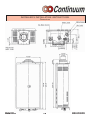
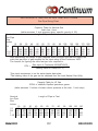
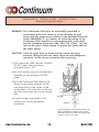
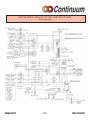
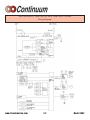
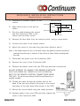
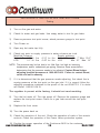
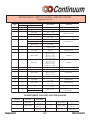
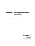
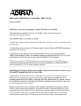
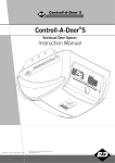
Installer’s Instructions
This section is for the Rinnai Certified
Installer only. If you are not certified
you are not authorized to install this
unit. The warranty may be voided due to
installation by a non-certified installer. For
information on becoming a Rinnai Certified
Installer, call
1-800-621-9419.
Contents
of Installer’s
Manual
Warnings ............................................................ 20
Performance Data ............................................. 21
Locating the Unit ............................................... 22
Dimensions ........................................................ 23
Recommended Piping for Installation .............. 24
Venting .......................................................... 25,26
Gas Piping Sizing Charts ................................. 27
Gas Piping Notes .............................................. 28
Water Piping Notes ........................................... 29
Pressure Relief Valve ....................................... 29
Electrical Connection Notes ............................. 30
Wiring Diagram ............................................ 31,32
Lighting the Unit ................................................ 33
Remote Controls .......................................... 34,35
Testing ............................................................... 36
Diagnostic Points .............................................. 37
Schematic Diagram ........................................... 38
Exploded View ........................................... 39 - 42
Parts List ................................................... 43 - 47
www.rinnaiamerica.com
800-621-9419
I N S TA L L E R ’ S I N S TA L L AT I O N I N S T R U C T I O N S
-Warnings-
This manual must be followed exactly.
1) Read the safety issues completely before installing the Continuum 2402.
2) This water heater is suitable for water (potable) heating or space heating.
- The piping connected to the Continuum 2402 must be approved for use in
potable water systems.
- Toxic chemicals such as those used for boiler water treatment are NOT to be
introduced to the Continuum 2402.
- The Continuum 2402, if it will be used as a potable water source, it must not
be connected to a system that was previously used with a nonpotable water
heating appliance.
3) The Continuum 2402 is not suitable for use as a spa heater.
4) The dip switches on the computer board have been preset at the factory and
should not be readjusted without the express knowledge and involvement of
Rinnai.
5) This unit is designed to be installed indoors using the proper vent piping to
exhaust by-products of combustion to the outside environment. Contact your
dealer or Rinnai for proper vent kits. DO NOT operate this unit without vent
piping connected. Exhaust gasses must be expelled outside the home. All
pipe joints shall be taped to help prevent leakage around joints. (Aluminum
tape is recommended.)
6) Maintain proper space around the unit for proper servicing and operation.
Minimum clearances from combustible materials are listed below.
Top of Heater
Back of Heater
Front of Heater
Sides of Heater
Floor
6
0
6
2
12
inches
inch
inches
inches
inches
7) Installer must install a Pressure relief valve. Pipe pressure relief discharge to a
drain or outside environment (see page 29).
8) The appliance should be located in an area where leakage of the unit or
connections will not result in damage to the area adjacent to the appliance or
to lower floors of the structure. When such locations cannot be avoided, it is
recommended that a suitable drain pan, adequately drained, be installed under
the appliance. The pan must not restrict combustion air flow.
www.rinnaiamerica.com
20
Model 2402
I N S TA L L E R ’ S I N S TA L L AT I O N I N S T R U C T I O N S
C O N T I N U U M O U T L E T F L O W D ATA
I N S TA L L E R ’ S I N S TA L L AT I O N I N S T R U C T I O N S
C O N T I N U U M P R E S S U R E D R O P C U RV E
Model 2402
2 1
800-621-9419
I N S TA L L E R ’ S I N S TA L L AT I O N I N S T R U C T I O N S
Locating the vent terminal
RECOMMENDED VENT/AIR INTAKE TERMINAL POSITION
Terminals should be so positioned as to avoid
products of combustion entering openings into
buildings or other flues or vents.
Vent/Air IntakeTerminal positions - MINIMUM dimensions.
REF
DESCRIPTION
DISTANCE IN INCHES
A
Directly below an Opening, Air Brick or Window.
B
Below a Gutter, Sanitary Pipework or Eaves.
C
From any Internal Corner.
12
D
Above Ground.
12
E
From an opposing wall or structure facing the Terminal.
24
F
From a Terminal facing a Terminal.
48
G
Vertically between Two Terminals on the same wall.
60
H
Horizontally between Two Terminals on the same wall.
12
J
From any External Corner.
12
K
Horizontally from any Opening, Air Brick, Window or Door.
12
L
Vertical Flue from wall (Flat or Pitched Roof).
24
www.rinnaiamerica.com
22
12
36 *
Model 2402
INSTALLER’S INSTALLATION INSTRUCTIONS
Dimensions
Model 2402
23
800-621-9419
I N S TA L L E R ’ S I N S TA L L AT I O N I N S T R U C T I O N S
RECOMMENDED PIPING FOR INSTALLATION
www.rinnaiamerica.com
24
Model 2402
I N S TA L L E R ’ S I N S TA L L AT I O N I N S T R U C T I O N S
Venting
The maximum allowable “Equivalent Length (D)” of vent pipe for the 2402 water heater is
41 feet (as determined using the formula below). If “D” is greater than 41, the vent/air
intake piping is too long or there are too many elbows, redesign the vent pipe run.
D = L + (B90 x 6) + (B45 x 1.5)
D =
L =
B90 =
B45 =
Total Equivalent Length of vent system.
Length of vent/air intake in feet.
Number of 90° elbows.
Number of 45° elbows.
To help prevent condensation in the vent/air intake piping, the combustion fan has two dip
switch settings. Dip switch number 2 is shipped from the factory set to the “OFF” position; this
is suitable for the maximum vent/air intake length.
Depending upon the vent/air intake length, Dip switch No. 2 may need to be adjusted to
compensate fan speed. Read the following instructions, to determine which position this switch
should be placed in.
When the Equivalent Length of vent pipe, D, is more than 22 feet, leave dip switch
number 2 in the “OFF” position.
When the Equivalent Length of vent pipe, D, is 22 feet or less, dip switch number 2 must
be moved to the “ON” position.
Dip switch # 2 is located in the top row of dip switches, 1 through 8 on the PC board. See the
diagram below to identify the proper switch. If you do not understand the following information,
contact Rinnai at 1-(800)621-9419 for assistance.
Do not alter dip switch number 2 before using formula, to determine the proper setting.
Example #1:
You have 6 feet of vent pipe, and two 90° elbows.
D = 6 + (2 x 6) + (0 x 1.5)
D = 18 Dip switch number 2 should be “ON”
Vent/air intake
piping length
Example #2:
You have 15 foot of vent pipe, one 90° elbow and two 45° elbows.
D = 15 + (1 x 6) + (2 x 1.5)
D = 24 Dip switch number 2 should be “OFF”
Warning: All other dip switches with the exception of dip switch No.2, shown in the diagram
below, MUST NOT be altered without the written consent of Rinnai. Unauthorized
adjustments can cause property damage, personal injury, scalding, or death.
Model 2402
25
800-621-9419
I N S TA L L E R ’ S I N S TA L L AT I O N I N S T R U C T I O N S
Venting
Vent/Air Intake for Continuum 2402 Hot Water Systems
The only vent/air intake system approved for use with this appliance by CSA is the Rinnai/
Ubbink vent system and components. The vent system must vent directly to the outside of a
building and use outside air for combustion as indicated in the diagrams below.
Horizontal Direct Vent Installation
Horizontal Direct
The Continuum 2402 may be installed on the internal
surface of an external wall using a standard Rinnai/Ubbink
vent system kit. A typical installation is shown in the
diagram to the right. The standard Rinnai/Ubbink vent
system kit consists of:
90° elbow
• One
One vent termination kit
• One
• discharge adaptor
Horizontal Extension Installation
Horizontal Extension
The Continuum 2402 may also be installed on an internal
wall which is near to an external wall. This can be done
using a combination of extension tube(s), 90° or 45°
elbow(s).
The maximum “EQUIVALENT LENGTH” of the vent/air intake
system is 41 feet, as calculated using the formula on page
29 (i.e. an installation with 23 feet of extension tubes, and
three 90° elbows). The maximum vertical height of the vent/
air intake system shall not exceed 5 feet unless an
approved condensation collar is used.
Vertical Direct Vent Installation
Vertical Direct
Roof Terminal
The Continuum 2402 can also be installed in roof spaces or
areas where vertical venting is required. Venting vertically
can be acheived using a combination of extension tube(s), a
vertical flue adaptor, a roof terminal, and a universal leadtile. The maximum “EQUIVALENT LENGTH” of the vent/air
intake system is 41 feet, as calculated using the formula on
page 29. However, the maximum HEIGHT of the vent
system is limited to 21 feet. The maximum vertical height of
the vent/air intake system shall not exceed 5 feet unless an
approved condensation collar is used.
www.rinnaiamerica.com
Up to 23 feet and 3 bends horizontal
Up to 5 feet vertical
26
Universal Lead-tile
Vertical Flue Adaptor
Model 2402
I N S TA L L E R ’ S I N S TA L L AT I O N I N S T R U C T I O N S
Gas Pipe Sizing Chart
Capacity Table for Natural Gas
cubic feet / hour
(table assumes .3 inch pressure drop, specific gravity of .60)
Length of Pipe in Feet
Nominal
Iron Pipe
Size
Inches
10
20
3/4
278 190
1
520 350
1-1/4 1050 730
1-1/2 1600 1100
30
152
285
590
890
40
130
245
500
760
50
115
215
440
670
60
105
195
400
610
70
96
180
370
560
80
90
170
350
530
90
84
160
320
490
100
79
150
305
460
125
72
130
275
410
150
64
120
250
380
175
59
110
225
350
200
55
100
210
320
After determining the length of pipe required select the pipe size that will supply the
cubic feet per hour of gas required for the input rating of the Continuum 2402.
The formula for figuring the cubic feet per hour required is:
CFH =
Gas Input of Continuum 2402(BTU/HR)
Heating Value of Gas(BTU/FT3)
*Gas input requirement is on the water heater data plate
*The heating value of the gas can be obtained from the local Natural Gas Utility
Capacity Table for LP Gas
BTUH of undiluted liquified petroleum gases
(table assumes 11 inches of water column pressure at the inlet, .5 inch drop)
Nominal
Length of Pipe in
Iron Pipe
Size
Inches
10
20
30
40
50
60
70
1/2
275 189 152 129
3/4
567 393 315 267 237 217 196
1
1071 732 590 504 448 409 378
1-1/4 2205 1496 1212 1039 913 834 771
Model 2402
27
Feet
80
90
100 125
150
185
346
724
173
322
677
162 146
307 275
630 567
252
511
800-621-9419
I N S TA L L E R ’ S I N S TA L L AT I O N I N S T R U C T I O N S
Gas Piping Notes
1) A manual gas control valve must be placed upon the gas inlet connection to the
Continuum 2402 before it is connected to the gas line. A union can be used on the
connection of the Continuum for the future servicing or disconnection of the unit.
2) Check the type of gas and the gas inlet pressure before connecting the Continuum
2402. If the Continuum 2402 is not of the gas type that the building is supplied
with, DO NOT connect the water heater. Contact the dealer for the proper unit to
match the gas type.
3) Minimum and Maximum Gas pressures are listed below:
* Minimum value is for input adjustment
Natural Gas:
WARNING:
Minimum 7" WC
Maximum 10.5" WC
Propane Gas:
Minimum 10"WC
Maximum 14" WC
Conversion of this unit from natural gas to propane or propane to
natural gas CANNOT be done in the field.
4) After completion of gas pipe connections, all joints including the heater must be
checked for gas-tightness by means of leak detector solution, soap and water, or an
equivalent nonflammable solution, as applicable. Caution: Since some leak test
solutions, including soap and water, may cause corrosion or stress cracking, the
piping must be rinsed with water after testing, unless it has been determined that
the leak solution is non-corrosive.
5) The Continuum 2402 must be leak tested before it is placed into operation.
6) The Continuum 2402 and its individual shut-off valve must be disconnected from the
gas supply piping system when pressure testing of the gas supply piping system at
test pressures equal to or greater than 1/2 psi.
7) Always use approved connectors to connect the unit to the gas line. Always purge
the gas line of any debris before connection to the water heater.
8) The Continuum 2402 must be isolated from the gas supply piping system by closing
it's individual manual shutoff valve during any pressure testing of the gas supply
piping system at test pressures less than 1/2 psi.
9) The Continuum 2402's Installation location must provide adequate Combustion and
Ventilation airflow.
www.rinnaiamerica.com
28
Model 2402
I N S TA L L E R ’ S I N S TA L L AT I O N I N S T R U C T I O N S
Water Piping Notes
1) A manual water control valve must be placed upon the water inlet connection to the
Continuum 2402 before it is connected to the water line. Unions may be used on both
the hot/cold water supply lines, for the future servicing or disconnection of the unit.
2) All soldering materials and piping must be compatible with potable water.
3) Purge the water line to remove from it all debris and air. Debris will damage the
Continuum 2402.
4) There is a wire mesh strainer on the Continuum 2402's inlet to discourage the
introduction of debris to the unit. It will need to be cleaned periodically.
DO NOT operate unit without filter in place.
WARNING: DO NOT reverse the inlet and outlet (cold and hot water) connections on
the unit. This would cause the Continuum 2402 to operate dangerously or not at all.
I N S TA L L E R ’ S I N S TA L L AT I O N I N S T R U C T I O N S
Pressure Relief Valve
1) ANSI code calls for the addition of an approved pressure relief valve to all water
heating systems.
2) The pressure relief valve must meet the following criteria: The relief valve must
comply with the standard for Relief Valves and Automatic Gas Shutoff Devices for
Hot Water Supply Systems ANSI Z21. 22. This relief valve must be rated at 150
PSI of pressure.
3) The relief valve should be added to the hot water outlet line per manufacturer's
instructions. DO NOT place any other type valve or shut off device between the
relief valve and the hot water heater.
4) The discharge from the pressure relief valve should be piped to the ground or into a
drain system to prevent exposure or possible burn hazards to humans or other plant
or animal life. Water discharged from the relief valve could cause severe burns
instantly, scalds and/or death.
5) Do not plug the relief valve and do not install any reducing fittings or other
restrictions in the relief line. The relief line should allow for complete drainage of
the valve and the line.
6) Pressure relief valve must be manually operated once a year to check for correct
operation.
7) Should overheating occur or the gas supply fail to shut off, turn off the manual gas
valve on the Continuum 2402.
Model 2402
29
800-621-9419
I N S TA L L E R ’ S I N S TA L L AT I O N I N S T R U C T I O N S
Electrical Connection Notes
WARNING: The Continuum 2402 must be electrically grounded in
accordance with local codes or in the absence of local
codes with the most recent edition of the National Electrical
Code, ANSl/NFPA 70. In Canada, all electrical wiring to the
Continuum 2424 should be in accordance with local codes
and the Canadian Electrical Code, CSA C22.1 Part1. Do not
rely on the gas or water piping to ground the metal parts of
the water heater.
CAUTION: Label all wires prior to disconnection when servicing
controls. Wiring errors can cause improper and dangerous
operation. Verify correct operation after servicing.
1 The Continuum 2402 requires 120VAC/
60 HZ. Power from a properly
grounded circuit, GFl.
PCB
2 An on/off switch must be provided and
installed for the incoming 120VAC
power.
3 Wire the Continuum 2402 exactly as
shown in the wiring diagram on the
next page and on the inside of the
cover panel. The blue wire is the hot
leg wire; the brown wire is the neutral
wire.
4 A green screw is provided in the
junction box for the grounding
connection.
Ground
ON/OFF
Your disconnect switch should be a type
that is suitable for outdoor use. Check
National Electrical Codes for proper type
switch to use in your area.
www.rinnaiamerica.com
30
Model 2402
I N S TA L L E R ’ S I N S TA L L AT I O N I N S T R U C T I O N S
Wiring Diagram
Model 2402
31
800-621-9419
I N S TA L L E R ’ S I N S TA L L AT I O N I N S T R U C T I O N S
Wiring Diagram
www.rinnaiamerica.com
32
Model 2402
I N S TA L L E R ’ S I N S TA L L AT I O N I N S T R U C T I O N S
Lighting the Unit
WARNING: If you do not follow these instructions exactly, a fire or
explosion may result causing property damage, personal injury or loss
of life.
1) This water heater does not have a pilot. It is equipped with a direct ignition
device which automatically lights the burner. DO NOT TRY TO LIGHT THE
BURNER BY HAND.
2) Before operating the Continuum 2402 smell all around the unit for gas. Be
sure to smell near the ground as leaking gas may settle there.
3) Turn the manual gas control valve on.
STOP!! READ THE SAFETY ISSUES ON PAGES 8 & 9
4) Turn on any hot water tap. The Continuum 2402 should light and begin
heating your water.
If the Continuum 2402 fails to light
1) DO NOT ATTEMPT TO LIGHT BY HAND.
2) Turn off the electrical power to the unit.
3) Turn off the manual gas control.
4) Wait 5 minutes, if you smell gas, go to a neighbor's house and call the gas
company or the fire department. If you do not smell gas, go to the next step.
5) Turn the manual gas control valve on.
6) Turn the electrical power to the unit on.
7) Turn on any hot water tap.
8) If the unit still fails to light, turn off the electricity and gas to the unit and call
Rinnai 1-800-621-9419.
Model 2402
33
800-621-9419
I N S TA L L E R ’ S I N S TA L L AT I O N I N S T R U C T I O N S
Remote Controls- General
The remote controls for the Continuum 2402 allow the customer to control the
functions of the water heater and to diagnose certain fault conditions.
The Main Controller model MC-45-3US is intended to be installed in the kitchen or
laundry area where the majority of the hot water is being used.
NOTE: The MC-45-3US has a temperature setpoint range of 96-140°F. This is the
only controller capable of temperature setpoints greater than 120°F.
The Bath Controller model BC-45-3US and Secondary Bath Controller model BSC45-3US are intended to be installed in a bath room close to a shower or tub. Both
of these controllers have temperature setpoint ranges of 96-120°F.
NOTE: Only one of each type of controller can be connected to one Continuum
2402 water heater. (i.e. Installations with two MC-45-3US, two BC-453US, or two BSC-45-3US controllers will not function properly.)
Before installing the remote controls, determine the most convenient location(s).
When deciding on the best location for the remote controls, please consider the
following items:
1) Place the controllers out of reach of small children.
2) Avoid locations where the controller(s) will become hot. (over the stove, near
the oven or a radiant heater.
3) Avoid direct sunlight. (The digital monitor can be difficult to read in direct
sunlight)
4) Avoid areas where the remote can be splashed with cooking water, oil or
sauce.
5) The remote control cables carry low voltage, 12VDC digital.
Every installation is different
Continuum 2402
Continuum 2402
Parallel
Series
Main Controller
Main Controller
Bath Controller
Bath Controller
The controls can be wired in series or in parallel depending on the distance from
the Continuum 2402 to the controls.
www.rinnaiamerica.com
34
Model 2402
I N S TA L L E R ’ S I N S TA L L AT I O N I N S T R U C T I O N S
Remote Controls - Installation
1)
outline of remote
Determine a suitable location for the
control.
securing screw
2)
Make three holes on the wall as
shown.
wire hole
1 1/16 inches
3 1/4 inches
securing screw
3)
Run the cable between the control
and the Continuum 2402 or the
control and the other control.
21/32 inch
4)
Remove the face plate from the remote control, using a screw driver.
5)
Connect the cable to the remote control.
6)
Mount the control to the wall using the holes drilled in step 2.
Note: If the cable cannot be run in the wall cavity, the plastic knockout should be
removed from the top or bottom of the control to allow flush mounting with
the wall
7)
Disconnect the power from the Continuum 2402.
8)
Remove the cover of the Continuum 2402.
9)
Remove the plastic cover from the PCB and electrical connections.
DO NOT ATTEMPT TO CONNECT THE REMOTE CONTROLS
WITH THE POWER ON, THERE'S 120 VOLT POTENTIAL,
NEXT TO THE REMOTE CONTROL CONNECTIONS INSIDE
THE UNIT. All service and wiring should be performed by a
certified installer.
10) Thread the cable through the access hole at the
base of the unit and connect the wires to the control
terminals on the right hand side bottom of the PCB.
11) Secure the control cable using the clamp provided.
12) Replace plastic cover over PCB and then replace the
cover of the Continuum 2402.
Model 2402
35
800-621-9419
I N S TA L L E R ’ S I N S TA L L AT I O N I N S T R U C T I O N S
Testing
1)
Turn on the gas and water.
2)
Check for water and gas leaks. Use soapy water to test for gas leaks.
3)
Remove pressure test point screw, attach pressure gauge to test point.
4)
Turn Power on.
5)
Open any hot water tap fully.
6)
Check test point or supply pressure in water columns per inch.
Manifold Pressure:
Supply pressure:
Natural Gas 3.9" Hi. fire
0.31" Lo. fire Natural Gas Min. 7" Max. 10.5"
LPG
5.1" Hi. fire
0.43" Lo. fire LPG
Min. 10" Max. 14"
NOTE: The pressure may be low due to too little flow, too high an incoming
temperature, and/or undersized gas piping. Examine these areas before
determining that the pressure needs to be adjusted. Contact Rinnai before
adjusting manifold pressures at 1-800-621-9419. Failure to contact Rinnai,
could void unit’s warranty.
7)
If it is determined that the gas pressure needs adjusting, first check the in
coming pressure at the test point on the gas inlet. If it is correct follow the
adjusting procedure contained in the pouch of the unit EXACTLY. If in doubt
call Rinnai 1-800-621-9419.
The regulator is pre-set at the factory, it should not need resetting.
8)
Turn the hot water off. Turn the power off. Remove the pressure guage and
replace the test point screw. Check for a gas leak around the test point
screw.
9)
Replace the front cover.
10) Turn the power back on.
11) Check the operation of the unit. Check the operation of each of the remote
controls. Check the operation of the Power failure protection system.
12) Explain the proper operation of the Continuum 2402 to the customer.
www.rinnaiamerica.com
36
Model 2402
I N S TA L L E R ’ S I N S TA L L AT I O N I N S T R U C T I O N S
Diagnostic Points
Flow
Chart
N0
Measurement Point
Con N0
Wire Color
Normal Value
Component
1
D1
Black - White
AC 108 - 132 V
Safety Device
2
H1
Black - Black
DC 10 - 13 V
Remote Control
3
J2
Red - Black
DC 11 - 13 V
Yellow - Black
DC 2 - 10 V
4
E4
White - White
DC 80 - 100 V
0.8 - 1.8 kΩ
Red - Black
DC 8 - 42 V
5
F
Yellow - Black
DC 11 - 13 V
White - Black
40 - 180 Hz
AC 100 - 160 V
(over DC 1µA)
Water Flow Sensor
By-Pass Solenoid Valve
Combustion Fan
6
C1
Yellow - EARTH
7
A1
Pink - Pink
8
J1
White - White
9
J4
Red - Red
10
A2
Red - Red
A3
Black - Black
Below 1Ω
Overheat Switch
Air Thermistor
DC 0.5 - 25 V
69 - 89 Ω
15°C 11.4 - l4.0 KΩ
30°C 6.4 - 7.8 KΩ
45°C 3.6 - 4.5 KΩ
60°C 2.2 - 2.7 KΩ
105°C 0.6 - 0.8 KΩ
15°C 11.4 - 14.O KΩ
30°C 6.4 - 7.8 KΩ
45°C 3.6 - 4.5 KΩ
60°C 2.2 - 2.7 KΩ
105°C 0.6 - 0.8 KΩ
Below 1Ω
Flame Rod
Modulating Valve
Thermistor
Thermistor
Thermal Fuse
11
J3
White - White
15°C 11.4 - 14.O KΩ
30°C 6.4 - 7.8 KΩ
45°C 3.6 - 4.5 KΩ
12
E5
Black - Black
AC 90 - 110 V
Spark Generator
13
E1
Pink - Black
DC 80 - 100 V
1.3 - 1.6 KΩ
Solenoid Valve 1
14
E2
Yellow - Black
DC 80 - 100 V
1.7 - 2.1 KΩ
Solenoid Valve 2
15
E3
Blue - Black
DC 80 - 100 V
1.7 - 2.1 KΩ
Solenoid Valve 3
16
I1
DC 11-13 V
Water Flow Control
(Geard Motor)
Red - Blue
Orange - Grey
TRANSFORMER VOLTAGES AND RESISTANCES
Connector
Wire Color
Nomal Value
D
Red - Black
AC 90 - 110 V
19 - 23 Ω
C
Grey -Brown
AC 30 - 50 V
2-4Ω
G
Green - Green
AC 12 - 16V
3.6 - 4.8 Ω
D1
Black - White
AC 108 - 132 V
20 - 24 Ω
C
Orange - Orange
AC 13 - 30V
0.5 - 0.7 Ω
C
Yellow - Brown
AC 180 - 220 V
0.23 - 0.3 KΩ
Model 2402
37
800-621-9419
I N S TA L L E R ’ S I N S TA L L AT I O N I N S T R U C T I O N S
Schematic Diagram
(Lime Sensor)
www.rinnaiamerica.com
38
Model 2402