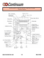
1
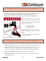
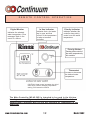
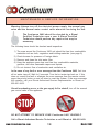
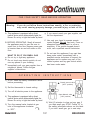
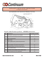
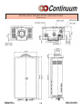
How to use your New
Continuous Flow
Water Heater
Model 2402
(indoor unit)
WARNING: If the information in these instructions is not followed
exactly, a fire or explosion may result causing property damage,
personal injury or death.
– Do not store or use gasoline or other flammable vapors and
liquids in the vicinity of this or any other appliance.
– WHAT TO DO IF YOU SMELL GAS
• Do not try to light any appliance.
• Do not touch any electrical switch; do not use any phone in
your building.
• Immediately call your gas supplier from a neighbor's phone.
Follow the gas supplier's instructions.
• If you cannot reach your gas supplier, call the fire department.
– Installation and service must be performed by a qualified
installer, service agency or the gas supplier.
S
P
E
C
I
F
I
C
A
T
I
O
N
S
Type of appliance
Temperature controlled continuous flow gas hot water system
Operation
With / without remote controls, mounted in kitchen, bathroom, etc.
Exhaust system
Direct Vent - Forced combustion
Rinnai model number
REU-2402FFU-US
Maximum/Minimum gas rate (Input BTU's)
180,000 BTU's - 19,000 BTU's Natural Gas
175,000 BTU's - 20,000 BTU's Propane Gas
Hot water capacity, (50°F rise)
0.6 to 6.5 GPM
Setpoint Temperatures (without remote)
108, 120, 130, 140, 150, 160, 170, or 180°F (Factory setting - 120°F)
Temperature range with remote
Keypads connected
MC controller :
96 - 140°F
BC and BSC controller : 96 - 120°F
Approved gas type
Natural or Propane - Ensure unit matches gas type it's being installed on.
Installation
Indoor Only
Dimensions
Height
Width
Depth
Weight
55 Lbs.
Efficiency rating
82%
Noise level
49 dB (A)
Connections
Gas supply
Cold water inlet
Hot water outlet
Ignition system
Direct electronic ignition
Electrical consumption
Normal
Standby
Anti-frost protection
Water temperature control
Simulation feedforward and feedback.
Water flow control
Water flow sensor and automatic electro-mechanical water flow control device
Minimum water supply pressure
40 PSI (Rinnai recommends 60-80 PSI for maximum performance)
Maximum water supply pressure
150 PSI
www.rinnaiamerica.com
26 3/4"
14 9/16"
7 7/8"
2
3/4" MNPT
3/4" MNPT
3/4" MNPT
92 watts
8 watts
90 watts
Model 2402
S
P
E
C
I
F
I
C
A
T
I
O
N
S
Appliance - AC 120 Volts - 60Hz.
Remote control DC 12 Volts (Digital)
Flame failure - Flame rod
Boiling protection - 203°F
Remaining flame (OHS) 194°F bi-metal switch
Safety devices
Thermal fuse 279°F
Automatic frost protection - Bi metal sensor & anti-frost heaters
Combustion fan rpm check - Integrated circuit
Over current - Glass fuse (3 amp)
If remote fails or becomes disconnected unit defaults to 100°F with water
flowing, this is an anti-scald feature.
Remote control
Remote control cable
Clearances from combustibles
MC-45-3 US
Main control Kitchen / Laundry
BC-45-3 US
Bathroom control
BSC-45-3 US
Second bathroom control
Non-polarized two core cable
Top of heater
6"
Front of heater
6"
Sides of heater
2"
Back of heater
0"
Floor
12"
Minimum and Maximum gas supply pressure
Natural Gas : *Minimum 6" W. C.
(NAT.)
**Maximum 10.5" W. C.
Manifold Gas Pressure
Natural Gas
LPG:
Warranty
Residential: Ten years heat exchanger / five years parts (see unit's warranty for details)
Commercial or Space Heating: Three years heat exchanger / three years parts
Minimum Wall Thickness
4"
Maximum Wall Thickness
20"
3.9" W. C. high fire
5.1" W. C. high fire
Propane Gas: *Minimum 10" W. C.
(LPG)
**Maximum 14" W. C.
0.31" W. C. low fire
0.43" W. C. low fire
*Minimum input pressure is for the purpose of input adjustments.
**Do not exceed maximum pressure.
Model 2402
3
800-621-9419
W
A
R
R
A
N
T
Y
Rinnai warrants the
continuous Hot Water Heater Model 2402, including any parts and components
thereof, to be free from any defects in materials and workmanship for the period specified below, subject to the
terms specified in this warranty. This warranty gives you specific legal rights and you may also have other rights
which vary from state to state.
This Warranty shall apply to the Continuum Continuous Hot Water Heater as follows:
CONDITION AND EXCEPTIONS
Item
Type of Failure Covered
Domestic Use
Period of Coverage
Commercial or Space Heat
Period of Coverage
Heat Exchanger
Defective Materials or
Workmanship
10 Years from Date of
Purchase
3 Years from Date of
Purchase
All other parts
and components
Defective Materials or
Workmanship
5 Years from Date of
Purchase
3 Years from Date of
Purchase
In the event of a malfunction, operational difficulty or failure of the product, or any part or any component thereof,
during the warranty term, resulting from defects in materials or workmanship, Rinnai will remedy the malfunction,
operational difficulty, or failure without charge to the owner of the water heater. The remedy will consist of repair
or replacement of the product at the option of Rinnai.
Rinnai will only provide those remedies listed above. The owner shall be responsible for all other costs, including
but not limited to shipping and delivery charges, labor associated with the removal and reinstallation of the
product or its components, and any other incidental costs such as other materials or permits that may be required
for installation.
This warranty DOES NOT cover any failures, operational difficulty or malfunction due to accident, abuse, misuse,
alteration, Acts of God, misapplications, improper installation or improper maintenance or service, lime damage, or from
any other cause other than defects in materials or workmanship. Warranty does not cover use as a pool or spa heater.
PROCEDURE FOR MAKING A CLAIM
In order to obtain the benefits of the warranty, contact your selling dealer or Rinnai at 800-621-9419 for the
location of the servicing dealer nearest you.
Proof of Purchase is required to institute a claim under this warranty. This document does not constitute proof-of
purchase.
LIMITATION ON IMPLIED WARRANTIES
Any implied warranties of merchantability and fitness applicable to the equipment arising under state law are
limited in duration to the period of coverage provided by this limited warranty, unless the period provided by state
law is less. Some States do not allow limitations on how long an implied warranty lasts, so the above limitation
may not apply to you.
DISCLAIMERS
Rinnai is not liable for any special, indirect or consequential damages, such as water damage, loss of use,
inconvenience, damage to person or property, whether arising in contract or tort.
Rinnai does not authorize any person or company to assume for it any other obligation or liability in connection
with the sale, application, engineering, installation, use, removal, return or replacement of its product, and no such
representations are binding on Rinnai.
Please DETACH the enclosed warranty registration card, fill it out, and drop it in the mail. Receipt of this
completed card by Rinnai will constitute proof-of purchase for your Rinnai Continuum 2402.
www.rinnaiamerica.com
4
Model 2402
C
O
N
T
E
N
T
S
Specifications .............................................................. 2,3
Warranty ........................................................................ 4
Owner's Installation Information ................................... 6
Features of your new Continuum ................................ 7
Safety Issues .............................................................. 8,9
Basic Operation ........................................................... 10
About Hot Water ......................................................... 11
Scalds-First Aid ........................................................... 11
Remote Control Operation ......................................... 12
Error Messages ........................................................... 13
Maintenance & Service Information...................... 14,15
Trouble Shooting and Common Questions ............... 16
Operating Instructions ............................................ 17,18
Care & Lime Condition Warning ................................ 18
Model 2402
5
800-621-9419
O W N E R ’ S I N S TA L L AT I O N I N F O R M AT I O N
This product must be installed by a Rinnai certified installer. Failure
to have the product installed by a Rinnai certified installer may result
in a voiding of the product's warranty.
This appliance must be installed in accordance with local codes, or in the
absence of local codes, the National Fuel Gas Code, ANSI Z223.1 and/or the
CAN/CGA-B149, Installation Codes.
Install this product indoors, DO NOT install outdoors.
Do Not use this appliance if any part has been underwater.
Immediately call a qualified service technician to inspect the appliance
and to replace any part of the control system and any gas control
which has been underwater.
Detailed instructions on the proper installation practices to follow for
the installation of your new continuous hot water heater are included
at the back of this manual.
For the Rinnai Certified Installer nearest
you call:
1-800-621-9419.
www.rinnaiamerica.com
6
Model 2402
F E AT U R E S O F Y O U R N E W C O N T I N U U M
)
)
)
)
)
)
)
)
)
)
The Continuum 2402 is one of the most advanced water heaters available. It supplies
hot water continuously at the temperature preset in the unit or at the temperature set on
the optional remote control(s). Remote controls are recommended for optimum
performance.
The Continuum 2402 never runs out of hot water. While electricity, water and gas
supplies are connected, hot water is available whenever the hot tap is open.
The gas burner lights automatically when the hot water tap is opened, and goes out
when the tap is closed. Ignition is electronic, there is no pilot light. When the hot water
tap is off, no gas is used. You save energy and money with the Continuum 2402.
The temperature of the outgoing hot water is constantly monitored by a built in sensor. If
the temperature of the outgoing water rises to more than 6 degrees above the selected
temperature (shown on the optional digital remote control) the gas burner will
automatically go out. The gas burner will re-ignite once the outgoing hot water
temperature falls below the selected temperature.
Built into the microprocessor of the Continuum 2402 is the ability to LIMIT THE
MAXIMUM TEMPERATURE of the hot water supplied by the Continuum 2402. Without
the connection of an optional remote control, the Continuum 2402 is preset to deliver
120 degree water.
With the optional remote the water temperature is adjustable from 96 to 140 with the
main controller and from 96 to 120 with the bath controller. The water temperature can
be preset at 108, 120, 130, or 140 by a certified Rinnai technician. If you require a
temperature other than 120 or what the remotes will give you, please contact your
Rinnai certified technician.
Error messages are displayed on the optional remote controls, simplifying service calls.
The Continuum 2402 incorporates a device to prevent the temperature from varying when
the water is off, then on again. It also incorporates a rapid response device for fast
heating.
The sound (noise) level from the Continuum 2402 is very low.
The Continuum 2402 is a very compact power vented device. It saves valuable floor and
wall space.
Model 2402
7
800-621-9419
S
A
F
E
T
Y
I
Always check water temperature by hand
before entering the shower or bath. The
temperature may have been changed.
S
S
U
E
S
The water temperature can only be adjusted
between 96°F and 110°F when the hot water
tap is open, and hot water is flowing.
Do not clean Remote Controls with solvents.
Use a soft damp cloth.
www.rinnaiamerica.com
8
Model 2402
S
A
F
E
T
Y
I
Depending on the weather conditions and the
length of the pipe between the Continuum
2402 and the tap in use, there may be a
variation between the temperatures displayed
at the Remote Control and the temperature of
the water at the tap.
S
S
U
E
S
The Continuum 2402 controls the water
temperature automatically. To do this it
sometimes needs to change the water flow
accordingly. The water flow from the hot
water tap may vary after the selected
temperature at the Remote Control is altered.
The water flow may also vary from summer to
winter, as incoming water temperatures differ.
The vent/air intake should be positioned away
from flammable materials, trees, shrubs, etc.
Vent Terminal
Do not connect vent to natural draft vents or
fireplaces, this unit can only be used with an
approved Rinnai/Ubbink vent kit and
components. Do not vent unit into other
rooms. Vent terminal must be outside.
Model 2402
9
800-621-9419
B
A
S
I
C
O
P
E
R
T
I
O
N
2
1
To take control of the Continuum 2402
all hot water taps must be closed.
Press the "Priority button" on the
Control you want to set the
temperature with, and the yellow
"Priority" indicator light will glow. This
indicates that the Continuum 2402 is
ready to supply hot water at the set
temperature as soon as a tap is
opened.
To operate the Continuum 2402 simply turn
any hot water tap on. This will automatically
light the burner providing hot water at the
preset temperature. If the optional remote
controls have been installed, the green “IN
USE” indicator will glow on all remote
controls.
3
A
4
Adjusting Temperature
Simply press the
or
button until
the required temperature is displayed
on the Digital Monitor.
The temperature can only be adjusted on
the Remote Control where the Priority
indicator is glowing, and the same
temperature will be displayed on all
Controls.
www.rinnaiamerica.com
1 0
Model 2402
A
B
O
U
T
H
O
T
W
A T
E
R
Hot Water Is Dangerous, especially for the young and the elderly or the
infirm. The Continuum 2402 allows you to precisely control the
temperature of your hot water, ensuring safe hot water temperatures.
Water Temperatures over 125°F can cause
severe burns instantly or death from scalds.
Hot Water can cause first degree burns with
exposure for as little as:
3 seconds at 140 °F
20 seconds at 130 °F
8 minutes at 120 °F
Test the temperature of the water with your
elbow before placing a child in the bath or
shower.
BURN
S
c
a
l
d
s
Do not leave a child or an infirm person in
the bath unsupervised.
-
F
i
r
s
t
A
i
d
1) Remove clothing; Remove all wet clothing, quickly. Wet clothing retains the heat.
2) Apply cold water for 30 minutes; Immediately submerge the burnt area in cold
water for 30 minutes to reduce the heat in the skin, preventing deeper burning.
Never use butter, oils or ointment to cover the burn. They may retain the heat.
3) Keep the scalded person warm; Place a blanket around the person.
4) Seek Medical Advice; Call your medical advice hotline and describe the scald,
follow their directions.
Model 2402
1 1
800-621-9419
R E M O T E
Digital Monitor
Indicates the selected
water temperature. Error
messages flash in the
event of a failure.
C O N T R O L
O P E R AT I O N
In Use Indicator
Indicates that a hot water
tap is open and that
control of the temperature
is taken at another
controller.
Priority Indicator
Indicates whether this
controller has priority
control over the water
temperature.
Priority Button
Pressing takes control of
the water temperature by
this controller.
Thermostat
Increase or decrease
the desired water
temperature.
CAUTION: Hotter water increases the risk of
scald injury. Before changing temperature
setting, see instruction manual
The Main Controller MC-45-3US is intended to be used in the kitchen,
laundry room or utility area, the Bath Controller BC-45-3US and the
Second Bath Controller BSC-45-3US are intended for installation in the
bathroom.
www.rinnaiamerica.com
1 2
Model 2402
E
R
R
O
R
M
E
S
S
A
G
E
S
The Continuum 2402 has the ability to check its own operation continuously. If a fault occurs,
an Error Message will flash on the Digital Monitor of the Remote Controls. This assists with
diagnosing the fault, and may enable you to overcome a problem without a service call. Please
quote the code displayed when inquiring about service.
NOTE: Failure to remedy faults may result in severe burns, scalds, and/or death.
Code
Displayed
Fault
Remedy
10
Air Supply or Exhaust Blockage
Check that nothing is blocking
the air intake or exhaust.
11
No Ignition
12
Flame Failure
Earthing Failure
Check that the gas is turned
on at the water heater and gas
meter. Check for obstructions
in flue outlet.
14
Thermal Fuse
Service Call
16
Over Temperature Warning
Service Call
32
Outgoing Water Temperature Sensor
Faulty
Service Call
33
Heat Exchanger Outgoing Water
Temperature Sensor Faulty
Service Call
34
Combustion Air Temperature
Sensor Faulty
Service Call
52
Mod. Solenoid Valve Answer Abnormal
Service Call
61
Combustion Fan Failure
Service Call
71
Solenoid Valve Driving Circuit Faulty
Service Call
72
Flame Sensing Device Faulty
Service Call
LC
Scale build-up in Heat Exchanger
Service Call
Model 2402
13
Check that the gas is turned
on at the water heater, gas
meter or cylinder.
800-621-9419
M A I N T E N A N C E & S E R V I C E I N F O R M AT I O N
Warning: Always turn off the electrical power supply, the manual gas
valve and the manual water control valve whenever servicing the unit.
The Continuum 2402 should be checked by a Rinnai
Certified Technician once a year. A Rinnai Certified
Technician should perform any repairs that may be
necessary.
The following items should be checked each inspection:
1) The area around the Continuum 2402 unit should be free from combustible
materials such as cloth, vegetation and building materials. (see page 9)
2) Check burners for presence of foreign debris.
3) Remove and clean the inlet water filter.
4) Keep the appliance area clear and free from combustible materials,
gasoline, and other flammable vapors and liquids.
5) Do not obstruct flow of combustion and ventilation air.
In the case of any fault or error message from the Continuum 2402, first turn
all hot water taps off. Wait for 5 seconds. Turn the hot water tap back on. If this
does not correct the fault or eliminate the error message from the remote control,
press the priority button on and off twice to reset the system. If the error message
still remains, call your Rinnai Authorized Service Representative or Rinnai at
800-621-9419.
Should overheating occur or the gas supply fail to shutoff, turn off the manual
gas control valve to the appliance.
DO NOT ATTEMPT TO SERVICE YOUR Continuum 2402 YOURSELF.
Call a Rinnai Authorized Service Technician or call Rinnai at 800-621-9419.
www.rinnaiamerica.com
1 4
Model 2402
M A I N T E N A N C E & S E R V I C E I N F O R M AT I O N
MAINTENANCE SUGGESTIONS
This water heater has been designed and constructed
for a long performance life when installed and operated
properly under normal conditions. Regular inspections,
as outlined in this section, are strongly recommended
as a means of keeping your heater operating efficiently.
1. Cleaning
The water heater must be cleaned annually.
Keep the water heater clear of dust and debris
especially in and around burner.
Cleaning procedures for the Continuum are as
follows:
1) Turn off and disconnect electrical power. Allow
to cool for one hour.
2) Remove the Front Panel by removing screws.
See parts breakdown on panels.
3) Use pressurized air to remove dust from around
main burner.
4) Use soft dry cloth to wipe cabinet.
DO NOT DAMAGE OR DISTORT ANY
PARTS OF HEATER.
DO NOT USE WET CLOTH OR
SPRAY CLEANERS ON BURNER.
2. Visual check of main burner flames.
The burner must flame evenly over the entire
surface when operating correctly. The flame must
burn with a clear, blue, stable flame. See the parts
breakdown of the burner for the location of view
ports. Any and all parts removed for inspection or
service must be replaced before operating the unit.
The flame pattern should be as shown in the
following Figures.
Model 2402
15
* VENT MAINTENANCE
* VENT SYSTEM
Must be checked annually for
blockage or deterioration. See
vent installation instructions.
* MAINTENANCEELECTRIC MOTORS
Motors are permanently
lubricated and need no
lubrication. Keep fan and
motor free of dust and dirt,
clean annually.
800-621-9419
TROUBLE SHOOTING AND COMMON QUESTIONS
Q - I don't have any hot water when I open the tap!
A - Make sure there is gas and electricity to the Continuum
2402.
(the power is turned on and the gas is turned on)
Q - When I was using the hot water, the water got cold!
A - If you adjusted the flow from the tap to lessen it, you
may have gone
below the minimum flow required. The Continuum 2402 requires .6
GPM to operate. If you mix the water with a tap and attempt to get a
temperature well below the temperature being controlled by the unit, it
may drop the flow below .6 GPM. Decrease the temperature supplied
by the Continuum 2402 at the remote control or increase your total
flow.
Q - White smoke comes out of the exhaust!
A - During colder weather when the exhaust
temperature is hotter than the
air, the exhaust fumes condense producing white steam.
Q - When I open a
A - Hot water must
hot tap. I do not immediately get hot water!
travel through your plumbing from the Continuum 2402
to the faucet. This can take from 2 to 10 or more seconds depending
upon your plumbing system.
Q
- After I turn off the hot water tap, the fan on the Continuum 2402
continues to run!
A
- The fan is designed to be on for 65 seconds after the flow of water
stops.This is to ensure constant water temperatures during rapid
starting and stopping, as well as exhausting any residual gas flue
products from the unit.
www.rinnaiamerica.com
1 6
Model 2402
FOR YOUR SAFETY READ BEFORE OPERATING
Warning:
If you do not follow these instructions exactly, a fire or explosion
may result causing property damage, personal injury or loss of life.
A. This appliance is equipped with a direct
ignition device which automatically lights the
burner. Do not try to light the burner by hand.
B. BEFORE OPERATING: Smell all around
the appliance area for gas. Be sure to
smell next to the floor because some gas
is heavier than air and will settle on the
floor.
•
•
•
WHAT TO DO IF YOU SMELL GAS
Do not try to light any appliance.
Do not touch any electric switch, do not
use any phone in your building.
Immediately call your gas supplier from a
neighbor’s phone. Follow the gas
supplier’s instructions.
O P E R A T I N G
•
If you cannot reach your gas supplier, call
the fire department.
C. Use only your hand to operate remote
control keypad. Do not use tools. Force or
attempted repair may result in a fire or
explosion. If the remote keypad doesn’t
work, call a qualified service technician.
D. Do not use this appliance if any part has
been under water. Immediately call a
qualified service technician to inspect the
appliance and to replace any part of the
control system and any gas control which
has been under water.
I N S T R U C T I O N S
1) STOP! Read the safety information above
before proceeding.
Closed manual valve
(“OFF” position)
2) Set the thermostat to lowest setting.
3) Turn off all electric power to the appliance.
Open Manual valve
(“ON” position)
4) This appliance is equipped with a direct
ignition device which automatically lights the
burner. Do not try to light the burner by hand.
5) Turn the manual valve located at gas
inlet of the appliance clockwise
to “OFF”.
Model 2402
6) Wait (5) minutes to clear out any gas. If
you then smell gas, STOP! Follow “B” in
the safety information above on this label.
If you don’t smell gas, go to next step.
1 7
800-621-9419
FOR YOUR SAFETY READ BEFORE OPERATING
7) Turn the manual valve located at the gas
inlet of appliance counterclockwise
to “ON”.
8) Turn on all electric power to the appliance.
9)
Set thermostat to desired setting.
10) If the appliance will not operate,
Follow the instructions “To Turn Off
Gas To Appliance” and call your
service technician or gas supplier.
To Turn Off Gas To Appliance
1) Set the thermostat to lowest setting.
2) Turn off all electric power to the appliance if service is to be performed.
3) Turn the manual valve at gas inlet of appliance clockwise
to “OFF”
CARE & LIME CONDITION WARNING
Care of Unit’s Exterior:
Keep the exterior cabinet clean. Use a soft cloth and warm water when cleaning the cabinet.
Do Not use volatile substances such as benzene and thinners, as they may ignite, or cause
fading of the paint.
Lime Condition Warning Signal:
If you notice “LC” flashing on the remote key pad, this means the unit is beginning to lime up,
and MUST be flushed. Contact a qualified Rinnai service technician to flush the appliance.
Failure to flush the appliance when “LC” is flashing, will cause damage to the heat exchanger.
Damage caused by lime build up is not covered by the unit’s warranty.
www.rinnaiamerica.com
1 8
Model 2402
Installer’s Instructions
This section is for the Rinnai Certified
Installer only. If you are not certified
you are not authorized to install this
unit. The warranty may be voided due to
installation by a non-certified installer. For
information on becoming a Rinnai Certified
Installer, call
1-800-621-9419.
Contents
of Installer’s
Manual
Warnings ............................................................ 20
Performance Data ............................................. 21
Locating the Unit ............................................... 22
Dimensions ........................................................ 23
Recommended Piping for Installation .............. 24
Venting .......................................................... 25,26
Gas Piping Sizing Charts ................................. 27
Gas Piping Notes .............................................. 28
Water Piping Notes ........................................... 29
Pressure Relief Valve ....................................... 29
Electrical Connection Notes ............................. 30
Wiring Diagram ............................................ 31,32
Lighting the Unit ................................................ 33
Remote Controls .......................................... 34,35
Testing ............................................................... 36
Diagnostic Points .............................................. 37
Schematic Diagram ........................................... 38
Exploded View ........................................... 39 - 42
Parts List ................................................... 43 - 47
www.rinnaiamerica.com
800-621-9419
I N S TA L L E R ’ S I N S TA L L AT I O N I N S T R U C T I O N S
-Warnings-
This manual must be followed exactly.
1) Read the safety issues completely before installing the Continuum 2402.
2) This water heater is suitable for water (potable) heating or space heating.
- The piping connected to the Continuum 2402 must be approved for use in
potable water systems.
- Toxic chemicals such as those used for boiler water treatment are NOT to be
introduced to the Continuum 2402.
- The Continuum 2402, if it will be used as a potable water source, it must not
be connected to a system that was previously used with a nonpotable water
heating appliance.
3) The Continuum 2402 is not suitable for use as a spa heater.
4) The dip switches on the computer board have been preset at the factory and
should not be readjusted without the express knowledge and involvement of
Rinnai.
5) This unit is designed to be installed indoors using the proper vent piping to
exhaust by-products of combustion to the outside environment. Contact your
dealer or Rinnai for proper vent kits. DO NOT operate this unit without vent
piping connected. Exhaust gasses must be expelled outside the home. All
pipe joints shall be taped to help prevent leakage around joints. (Aluminum
tape is recommended.)
6) Maintain proper space around the unit for proper servicing and operation.
Minimum clearances from combustible materials are listed below.
Top of Heater
Back of Heater
Front of Heater
Sides of Heater
Floor
6
0
6
2
12
inches
inch
inches
inches
inches
7) Installer must install a Pressure relief valve. Pipe pressure relief discharge to a
drain or outside environment (see page 29).
8) The appliance should be located in an area where leakage of the unit or
connections will not result in damage to the area adjacent to the appliance or
to lower floors of the structure. When such locations cannot be avoided, it is
recommended that a suitable drain pan, adequately drained, be installed under
the appliance. The pan must not restrict combustion air flow.
www.rinnaiamerica.com
20
Model 2402
I N S TA L L E R ’ S I N S TA L L AT I O N I N S T R U C T I O N S
C O N T I N U U M O U T L E T F L O W D ATA
I N S TA L L E R ’ S I N S TA L L AT I O N I N S T R U C T I O N S
C O N T I N U U M P R E S S U R E D R O P C U RV E
Model 2402
2 1
800-621-9419
I N S TA L L E R ’ S I N S TA L L AT I O N I N S T R U C T I O N S
Locating the vent terminal
RECOMMENDED VENT/AIR INTAKE TERMINAL POSITION
Terminals should be so positioned as to avoid
products of combustion entering openings into
buildings or other flues or vents.
Vent/Air IntakeTerminal positions - MINIMUM dimensions.
REF
DESCRIPTION
DISTANCE IN INCHES
A
Directly below an Opening, Air Brick or Window.
B
Below a Gutter, Sanitary Pipework or Eaves.
C
From any Internal Corner.
12
D
Above Ground.
12
E
From an opposing wall or structure facing the Terminal.
24
F
From a Terminal facing a Terminal.
48
G
Vertically between Two Terminals on the same wall.
60
H
Horizontally between Two Terminals on the same wall.
12
J
From any External Corner.
12
K
Horizontally from any Opening, Air Brick, Window or Door.
12
L
Vertical Flue from wall (Flat or Pitched Roof).
24
www.rinnaiamerica.com
22
12
36 *
Model 2402
INSTALLER’S INSTALLATION INSTRUCTIONS
Dimensions
Model 2402
23
800-621-9419
I N S TA L L E R ’ S I N S TA L L AT I O N I N S T R U C T I O N S
RECOMMENDED PIPING FOR INSTALLATION
www.rinnaiamerica.com
24
Model 2402
I N S TA L L E R ’ S I N S TA L L AT I O N I N S T R U C T I O N S
Venting
The maximum allowable “Equivalent Length (D)” of vent pipe for the 2402 water heater is
41 feet (as determined using the formula below). If “D” is greater than 41, the vent/air
intake piping is too long or there are too many elbows, redesign the vent pipe run.
D = L + (B90 x 6) + (B45 x 1.5)
D =
L =
B90 =
B45 =
Total Equivalent Length of vent system.
Length of vent/air intake in feet.
Number of 90° elbows.
Number of 45° elbows.
To help prevent condensation in the vent/air intake piping, the combustion fan has two dip
switch settings. Dip switch number 2 is shipped from the factory set to the “OFF” position; this
is suitable for the maximum vent/air intake length.
Depending upon the vent/air intake length, Dip switch No. 2 may need to be adjusted to
compensate fan speed. Read the following instructions, to determine which position this switch
should be placed in.
When the Equivalent Length of vent pipe, D, is more than 22 feet, leave dip switch
number 2 in the “OFF” position.
When the Equivalent Length of vent pipe, D, is 22 feet or less, dip switch number 2 must
be moved to the “ON” position.
Dip switch # 2 is located in the top row of dip switches, 1 through 8 on the PC board. See the
diagram below to identify the proper switch. If you do not understand the following information,
contact Rinnai at 1-(800)621-9419 for assistance.
Do not alter dip switch number 2 before using formula, to determine the proper setting.
Example #1:
You have 6 feet of vent pipe, and two 90° elbows.
D = 6 + (2 x 6) + (0 x 1.5)
D = 18 Dip switch number 2 should be “ON”
Vent/air intake
piping length
Example #2:
You have 15 foot of vent pipe, one 90° elbow and two 45° elbows.
D = 15 + (1 x 6) + (2 x 1.5)
D = 24 Dip switch number 2 should be “OFF”
Warning: All other dip switches with the exception of dip switch No.2, shown in the diagram
below, MUST NOT be altered without the written consent of Rinnai. Unauthorized
adjustments can cause property damage, personal injury, scalding, or death.
Model 2402
25
800-621-9419
I N S TA L L E R ’ S I N S TA L L AT I O N I N S T R U C T I O N S
Venting
Vent/Air Intake for Continuum 2402 Hot Water Systems
The only vent/air intake system approved for use with this appliance by CSA is the Rinnai/
Ubbink vent system and components. The vent system must vent directly to the outside of a
building and use outside air for combustion as indicated in the diagrams below.
Horizontal Direct Vent Installation
Horizontal Direct
The Continuum 2402 may be installed on the internal
surface of an external wall using a standard Rinnai/Ubbink
vent system kit. A typical installation is shown in the
diagram to the right. The standard Rinnai/Ubbink vent
system kit consists of:
90° elbow
• One
One vent termination kit
• One
• discharge adaptor
Horizontal Extension Installation
Horizontal Extension
The Continuum 2402 may also be installed on an internal
wall which is near to an external wall. This can be done
using a combination of extension tube(s), 90° or 45°
elbow(s).
The maximum “EQUIVALENT LENGTH” of the vent/air intake
system is 41 feet, as calculated using the formula on page
29 (i.e. an installation with 23 feet of extension tubes, and
three 90° elbows). The maximum vertical height of the vent/
air intake system shall not exceed 5 feet unless an
approved condensation collar is used.
Vertical Direct Vent Installation
Vertical Direct
Roof Terminal
The Continuum 2402 can also be installed in roof spaces or
areas where vertical venting is required. Venting vertically
can be acheived using a combination of extension tube(s), a
vertical flue adaptor, a roof terminal, and a universal leadtile. The maximum “EQUIVALENT LENGTH” of the vent/air
intake system is 41 feet, as calculated using the formula on
page 29. However, the maximum HEIGHT of the vent
system is limited to 21 feet. The maximum vertical height of
the vent/air intake system shall not exceed 5 feet unless an
approved condensation collar is used.
www.rinnaiamerica.com
Up to 23 feet and 3 bends horizontal
Up to 5 feet vertical
26
Universal Lead-tile
Vertical Flue Adaptor
Model 2402
I N S TA L L E R ’ S I N S TA L L AT I O N I N S T R U C T I O N S
Gas Pipe Sizing Chart
Capacity Table for Natural Gas
cubic feet / hour
(table assumes .3 inch pressure drop, specific gravity of .60)
Length of Pipe in Feet
Nominal
Iron Pipe
Size
Inches
10
20
3/4
278 190
1
520 350
1-1/4 1050 730
1-1/2 1600 1100
30
152
285
590
890
40
130
245
500
760
50
115
215
440
670
60
105
195
400
610
70
96
180
370
560
80
90
170
350
530
90
84
160
320
490
100
79
150
305
460
125
72
130
275
410
150
64
120
250
380
175
59
110
225
350
200
55
100
210
320
After determining the length of pipe required select the pipe size that will supply the
cubic feet per hour of gas required for the input rating of the Continuum 2402.
The formula for figuring the cubic feet per hour required is:
CFH =
Gas Input of Continuum 2402(BTU/HR)
Heating Value of Gas(BTU/FT3)
*Gas input requirement is on the water heater data plate
*The heating value of the gas can be obtained from the local Natural Gas Utility
Capacity Table for LP Gas
BTUH of undiluted liquified petroleum gases
(table assumes 11 inches of water column pressure at the inlet, .5 inch drop)
Nominal
Length of Pipe in
Iron Pipe
Size
Inches
10
20
30
40
50
60
70
1/2
275 189 152 129
3/4
567 393 315 267 237 217 196
1
1071 732 590 504 448 409 378
1-1/4 2205 1496 1212 1039 913 834 771
Model 2402
27
Feet
80
90
100 125
150
185
346
724
173
322
677
162 146
307 275
630 567
252
511
800-621-9419
I N S TA L L E R ’ S I N S TA L L AT I O N I N S T R U C T I O N S
Gas Piping Notes
1) A manual gas control valve must be placed upon the gas inlet connection to the
Continuum 2402 before it is connected to the gas line. A union can be used on the
connection of the Continuum for the future servicing or disconnection of the unit.
2) Check the type of gas and the gas inlet pressure before connecting the Continuum
2402. If the Continuum 2402 is not of the gas type that the building is supplied
with, DO NOT connect the water heater. Contact the dealer for the proper unit to
match the gas type.
3) Minimum and Maximum Gas pressures are listed below:
* Minimum value is for input adjustment
Natural Gas:
WARNING:
Minimum 7" WC
Maximum 10.5" WC
Propane Gas:
Minimum 10"WC
Maximum 14" WC
Conversion of this unit from natural gas to propane or propane to
natural gas CANNOT be done in the field.
4) After completion of gas pipe connections, all joints including the heater must be
checked for gas-tightness by means of leak detector solution, soap and water, or an
equivalent nonflammable solution, as applicable. Caution: Since some leak test
solutions, including soap and water, may cause corrosion or stress cracking, the
piping must be rinsed with water after testing, unless it has been determined that
the leak solution is non-corrosive.
5) The Continuum 2402 must be leak tested before it is placed into operation.
6) The Continuum 2402 and its individual shut-off valve must be disconnected from the
gas supply piping system when pressure testing of the gas supply piping system at
test pressures equal to or greater than 1/2 psi.
7) Always use approved connectors to connect the unit to the gas line. Always purge
the gas line of any debris before connection to the water heater.
8) The Continuum 2402 must be isolated from the gas supply piping system by closing
it's individual manual shutoff valve during any pressure testing of the gas supply
piping system at test pressures less than 1/2 psi.
9) The Continuum 2402's Installation location must provide adequate Combustion and
Ventilation airflow.
www.rinnaiamerica.com
28
Model 2402
I N S TA L L E R ’ S I N S TA L L AT I O N I N S T R U C T I O N S
Water Piping Notes
1) A manual water control valve must be placed upon the water inlet connection to the
Continuum 2402 before it is connected to the water line. Unions may be used on both
the hot/cold water supply lines, for the future servicing or disconnection of the unit.
2) All soldering materials and piping must be compatible with potable water.
3) Purge the water line to remove from it all debris and air. Debris will damage the
Continuum 2402.
4) There is a wire mesh strainer on the Continuum 2402's inlet to discourage the
introduction of debris to the unit. It will need to be cleaned periodically.
DO NOT operate unit without filter in place.
WARNING: DO NOT reverse the inlet and outlet (cold and hot water) connections on
the unit. This would cause the Continuum 2402 to operate dangerously or not at all.
I N S TA L L E R ’ S I N S TA L L AT I O N I N S T R U C T I O N S
Pressure Relief Valve
1) ANSI code calls for the addition of an approved pressure relief valve to all water
heating systems.
2) The pressure relief valve must meet the following criteria: The relief valve must
comply with the standard for Relief Valves and Automatic Gas Shutoff Devices for
Hot Water Supply Systems ANSI Z21. 22. This relief valve must be rated at 150
PSI of pressure.
3) The relief valve should be added to the hot water outlet line per manufacturer's
instructions. DO NOT place any other type valve or shut off device between the
relief valve and the hot water heater.
4) The discharge from the pressure relief valve should be piped to the ground or into a
drain system to prevent exposure or possible burn hazards to humans or other plant
or animal life. Water discharged from the relief valve could cause severe burns
instantly, scalds and/or death.
5) Do not plug the relief valve and do not install any reducing fittings or other
restrictions in the relief line. The relief line should allow for complete drainage of
the valve and the line.
6) Pressure relief valve must be manually operated once a year to check for correct
operation.
7) Should overheating occur or the gas supply fail to shut off, turn off the manual gas
valve on the Continuum 2402.
Model 2402
29
800-621-9419
I N S TA L L E R ’ S I N S TA L L AT I O N I N S T R U C T I O N S
Electrical Connection Notes
WARNING: The Continuum 2402 must be electrically grounded in
accordance with local codes or in the absence of local
codes with the most recent edition of the National Electrical
Code, ANSl/NFPA 70. In Canada, all electrical wiring to the
Continuum 2424 should be in accordance with local codes
and the Canadian Electrical Code, CSA C22.1 Part1. Do not
rely on the gas or water piping to ground the metal parts of
the water heater.
CAUTION: Label all wires prior to disconnection when servicing
controls. Wiring errors can cause improper and dangerous
operation. Verify correct operation after servicing.
1 The Continuum 2402 requires 120VAC/
60 HZ. Power from a properly
grounded circuit, GFl.
PCB
2 An on/off switch must be provided and
installed for the incoming 120VAC
power.
3 Wire the Continuum 2402 exactly as
shown in the wiring diagram on the
next page and on the inside of the
cover panel. The blue wire is the hot
leg wire; the brown wire is the neutral
wire.
Ground
4 A green screw is provided in the
junction box for the grounding
connection.
ON/OFF
Your disconnect switch should be a type
that is suitable for outdoor use. Check
National Electrical Codes for proper type
switch to use in your area.
www.rinnaiamerica.com
30
Model 2402
I N S TA L L E R ’ S I N S TA L L AT I O N I N S T R U C T I O N S
Wiring Diagram
Model 2402
31
800-621-9419
I N S TA L L E R ’ S I N S TA L L AT I O N I N S T R U C T I O N S
Wiring Diagram
www.rinnaiamerica.com
32
Model 2402
I N S TA L L E R ’ S I N S TA L L AT I O N I N S T R U C T I O N S
Lighting the Unit
WARNING: If you do not follow these instructions exactly, a fire or
explosion may result causing property damage, personal injury or loss
of life.
1) This water heater does not have a pilot. It is equipped with a direct ignition
device which automatically lights the burner. DO NOT TRY TO LIGHT THE
BURNER BY HAND.
2) Before operating the Continuum 2402 smell all around the unit for gas. Be
sure to smell near the ground as leaking gas may settle there.
3) Turn the manual gas control valve on.
STOP!! READ THE SAFETY ISSUES ON PAGES 8 & 9
4) Turn on any hot water tap. The Continuum 2402 should light and begin
heating your water.
If the Continuum 2402 fails to light
1) DO NOT ATTEMPT TO LIGHT BY HAND.
2) Turn off the electrical power to the unit.
3) Turn off the manual gas control.
4) Wait 5 minutes, if you smell gas, go to a neighbor's house and call the gas
company or the fire department. If you do not smell gas, go to the next step.
5) Turn the manual gas control valve on.
6) Turn the electrical power to the unit on.
7) Turn on any hot water tap.
8) If the unit still fails to light, turn off the electricity and gas to the unit and call
Rinnai 1-800-621-9419.
Model 2402
33
800-621-9419
I N S TA L L E R ’ S I N S TA L L AT I O N I N S T R U C T I O N S
Remote Controls- General
The remote controls for the Continuum 2402 allow the customer to control the
functions of the water heater and to diagnose certain fault conditions.
The Main Controller model MC-45-3US is intended to be installed in the kitchen or
laundry area where the majority of the hot water is being used.
NOTE: The MC-45-3US has a temperature setpoint range of 96-140°F. This is the
only controller capable of temperature setpoints greater than 120°F.
The Bath Controller model BC-45-3US and Secondary Bath Controller model BSC45-3US are intended to be installed in a bath room close to a shower or tub. Both
of these controllers have temperature setpoint ranges of 96-120°F.
NOTE: Only one of each type of controller can be connected to one Continuum
2402 water heater. (i.e. Installations with two MC-45-3US, two BC-453US, or two BSC-45-3US controllers will not function properly.)
Before installing the remote controls, determine the most convenient location(s).
When deciding on the best location for the remote controls, please consider the
following items:
1) Place the controllers out of reach of small children.
2) Avoid locations where the controller(s) will become hot. (over the stove, near
the oven or a radiant heater.
3) Avoid direct sunlight. (The digital monitor can be difficult to read in direct
sunlight)
4) Avoid areas where the remote can be splashed with cooking water, oil or
sauce.
5) The remote control cables carry low voltage, 12VDC digital.
Every installation is different
Continuum 2402
Continuum 2402
Parallel
Series
Main Controller
Main Controller
Bath Controller
Bath Controller
The controls can be wired in series or in parallel depending on the distance from
the Continuum 2402 to the controls.
www.rinnaiamerica.com
34
Model 2402
I N S TA L L E R ’ S I N S TA L L AT I O N I N S T R U C T I O N S
Remote Controls - Installation
1)
outline of remote
Determine a suitable location for the
control.
securing screw
2)
Make three holes on the wall as
shown.
wire hole
1 1/16 inches
3 1/4 inches
securing screw
3)
Run the cable between the control
and the Continuum 2402 or the
control and the other control.
21/32 inch
4)
Remove the face plate from the remote control, using a screw driver.
5)
Connect the cable to the remote control.
6)
Mount the control to the wall using the holes drilled in step 2.
Note: If the cable cannot be run in the wall cavity, the plastic knockout should be
removed from the top or bottom of the control to allow flush mounting with
the wall
7)
Disconnect the power from the Continuum 2402.
8)
Remove the cover of the Continuum 2402.
9)
Remove the plastic cover from the PCB and electrical connections.
DO NOT ATTEMPT TO CONNECT THE REMOTE CONTROLS
WITH THE POWER ON, THERE'S 120 VOLT POTENTIAL,
NEXT TO THE REMOTE CONTROL CONNECTIONS INSIDE
THE UNIT. All service and wiring should be performed by a
certified installer.
10) Thread the cable through the access hole at the
base of the unit and connect the wires to the control
terminals on the right hand side bottom of the PCB.
11) Secure the control cable using the clamp provided.
12) Replace plastic cover over PCB and then replace the
cover of the Continuum 2402.
Model 2402
35
800-621-9419
I N S TA L L E R ’ S I N S TA L L AT I O N I N S T R U C T I O N S
Testing
1)
Turn on the gas and water.
2)
Check for water and gas leaks. Use soapy water to test for gas leaks.
3)
Remove pressure test point screw, attach pressure gauge to test point.
4)
Turn Power on.
5)
Open any hot water tap fully.
6)
Check test point or supply pressure in water columns per inch.
Manifold Pressure:
Supply pressure:
Natural Gas 3.9" Hi. fire
0.31" Lo. fire Natural Gas Min. 7" Max. 10.5"
LPG
5.1" Hi. fire
0.43" Lo. fire LPG
Min. 10" Max. 14"
NOTE: The pressure may be low due to too little flow, too high an incoming
temperature, and/or undersized gas piping. Examine these areas before
determining that the pressure needs to be adjusted. Contact Rinnai before
adjusting manifold pressures at 1-800-621-9419. Failure to contact Rinnai,
could void unit’s warranty.
7)
If it is determined that the gas pressure needs adjusting, first check the in
coming pressure at the test point on the gas inlet. If it is correct follow the
adjusting procedure contained in the pouch of the unit EXACTLY. If in doubt
call Rinnai 1-800-621-9419.
The regulator is pre-set at the factory, it should not need resetting.
8)
Turn the hot water off. Turn the power off. Remove the pressure guage and
replace the test point screw. Check for a gas leak around the test point
screw.
9)
Replace the front cover.
10) Turn the power back on.
11) Check the operation of the unit. Check the operation of each of the remote
controls. Check the operation of the Power failure protection system.
12) Explain the proper operation of the Continuum 2402 to the customer.
www.rinnaiamerica.com
36
Model 2402
I N S TA L L E R ’ S I N S TA L L AT I O N I N S T R U C T I O N S
Diagnostic Points
Flow
Chart
N0
Measurement Point
Con N0
Wire Color
Normal Value
Component
1
D1
Black - White
AC 108 - 132 V
Safety Device
2
H1
Black - Black
DC 10 - 13 V
Remote Control
3
J2
Red - Black
DC 11 - 13 V
Yellow - Black
DC 2 - 10 V
4
E4
White - White
DC 80 - 100 V
0.8 - 1.8 kΩ
Red - Black
DC 8 - 42 V
5
F
Yellow - Black
DC 11 - 13 V
White - Black
40 - 180 Hz
AC 100 - 160 V
(over DC 1µA)
Water Flow Sensor
By-Pass Solenoid Valve
Combustion Fan
6
C1
Yellow - EARTH
7
A1
Pink - Pink
8
J1
White - White
9
J4
Red - Red
10
A2
Red - Red
A3
Black - Black
Below 1Ω
Overheat Switch
Air Thermistor
DC 0.5 - 25 V
69 - 89 Ω
15°C 11.4 - l4.0 KΩ
30°C 6.4 - 7.8 KΩ
45°C 3.6 - 4.5 KΩ
60°C 2.2 - 2.7 KΩ
105°C 0.6 - 0.8 KΩ
15°C 11.4 - 14.O KΩ
30°C 6.4 - 7.8 KΩ
45°C 3.6 - 4.5 KΩ
60°C 2.2 - 2.7 KΩ
105°C 0.6 - 0.8 KΩ
Below 1Ω
Flame Rod
Modulating Valve
Thermistor
Thermistor
Thermal Fuse
11
J3
White - White
15°C 11.4 - 14.O KΩ
30°C 6.4 - 7.8 KΩ
45°C 3.6 - 4.5 KΩ
12
E5
Black - Black
AC 90 - 110 V
Spark Generator
13
E1
Pink - Black
DC 80 - 100 V
1.3 - 1.6 KΩ
Solenoid Valve 1
14
E2
Yellow - Black
DC 80 - 100 V
1.7 - 2.1 KΩ
Solenoid Valve 2
15
E3
Blue - Black
DC 80 - 100 V
1.7 - 2.1 KΩ
Solenoid Valve 3
16
I1
DC 11-13 V
Water Flow Control
(Geard Motor)
Red - Blue
Orange - Grey
TRANSFORMER VOLTAGES AND RESISTANCES
Connector
Wire Color
Nomal Value
D
Red - Black
AC 90 - 110 V
19 - 23 Ω
C
Grey -Brown
AC 30 - 50 V
2-4Ω
G
Green - Green
AC 12 - 16V
3.6 - 4.8 Ω
D1
Black - White
AC 108 - 132 V
20 - 24 Ω
C
Orange - Orange
AC 13 - 30V
0.5 - 0.7 Ω
C
Yellow - Brown
AC 180 - 220 V
0.23 - 0.3 KΩ
Model 2402
37
800-621-9419
I N S TA L L E R ’ S I N S TA L L AT I O N I N S T R U C T I O N S
Schematic Diagram
(Lime Sensor)
www.rinnaiamerica.com
38
Model 2402
I N S TA L L E R ’ S I N S TA L L AT I O N I N S T R U C T I O N S
Exploded View - Cabinet
Model 2402
39
800-621-9419
I N S TA L L E R ’ S I N S TA L L AT I O N I N S T R U C T I O N S
Exploded View - Internals
www.rinnaiamerica.com
40
Model 2402
I N S TA L L E R ’ S I N S TA L L AT I O N I N S T R U C T I O N S
Exploded View - Internals
Model 2402
4 1
800-621-9419
I N S TA L L E R ’ S I N S TA L L AT I O N I N S T R U C T I O N S
Exploded View - Electrical
www.rinnaiamerica.com
42
Model 2402
I N S TA L L E R ’ S I N S TA L L AT I O N I N S T R U C T I O N S
Parts List
Number
Description
Part Number
Quantity
002
Casing Assembly
DU162-1860
1
006
Front Panel Assembly-9
DU162-111-9
1
010
Wall Fitting Bracket
BU183-115-3
1
011
Wall Fitting Bracket Bottom
BU162-107-2
1
013
Connection Reinforcement Panel
DU162-1863
1
021
Rubber Plug
AU105-113
1
022
Cable Connection
BU56-602-N
1
100
Gas Connection (3/4" NPT)B
CU195-211-2
1
101
Test Point Screw
C10D-5
1
102
Gas Control Connecting
CU162-1880
1
103
Gas Control Assembly
C36E-30-S
1
104
Manifold Assembly - A (LPG)
CU155-410-A
1
104
Manifold Assembly - B (Nat.G)
CU155-410-B
1
105
Main Injector
BU155-210
18
106
Damper A(NAT.G)
BU155-414-A
1
106
Damper B (LPG)
BU155-414-B
1
107
Burner Unit Assembly F .
CU162-210
1
108
Burner Case Front
CU155-222
1
110
Side Type Sleeve Burner Assembly
B3A1-4
18
111
Burner Case Bottom Panel
CU155-223-T
1
112
Slope Blate
BU155-228
1
113
Burner Case Back Panel
CU155-224
1
114
Electrode Holder
AH24-342
2
115
Electrode
AH24-344
2
Model 2402
43
800-621-9419
I N S TA L L E R ’ S I N S TA L L AT I O N I N S T R U C T I O N S
Parts List
Number
Description
Part Number
Quantity
116
Ignition Target
AH24-341
2
117
Electrode Packing
AH24-346
2
118
Electrode Holder
AU129-319
1
119
Flame Rod
AH24-345
1
120
Electrode Packing
AH24-348
1
121
Combustion Chamber Front Plate
BU155-211
1
122
Combution Chamber Braket
CU162-203
1
123
Heat Exchanger Complete Assy
DU162-1879
1
124
Combustion Chamber Bottom Stand
BU155-227
1
125
Unit Brancket
BU162-1886
1
126
Screw
AU39-965
1
150
Blower Motor B
CU162-615-2
1
151
Air Inlet Box Assy B
CU162-810-2
1
152
Air Inlet Box Cover
BU162-815
1
153
Back Pressure Pipe
BU162-816
1
154
CK Cramp
ES-10037-1
3
155
Pressure Tube
AU161-665-a
1
156
Flue Connection Assy
BU162-820
1
158
Blower Motor Assy
CU162-610-2
1
159
Air Inlet Packing
BU162-617
1
160
Fan Connecting Packing
AU183-562
1
400
Water Inlet ( 314" NPT)
H73-501-2
1
401
Water Filter Assy
H73-511
1
402
Rectifier
M8D 1-11
1
www.rinnaiamerica.com
44
Model 2402
I N S TA L L E R ’ S I N S TA L L AT I O N I N S T R U C T I O N S
Parts List
Number
Description
Part Number
Quantity
403
Water Flow Servo & Sensor
M8E-4-6
1
404
Joint
M6H4-2
1
405
Water Solenoid Valve
M6H-4
1
408
Hot Water Outlet (3/4"NPT)
U211-321-2
1
409
Plug Band B
AU142-445
1
410
Drain
AU 142-444
1
700
PCB
CU 162-1855
1
701
Surge Protector
BBF9-630
1
702
Glass Fuse
EP-103-33
2
706
PCB Cover
CU163-608
1
707
Fuse Cover
AU155-1560
1
708
Ignitor
EI-145
1
709
High Tension Cord
BH38-710-250
2
710
Transformer
ET-260
1
711
120V Anti-Frost Heater
BU195-1879
1
712
Anti-Frost Heater Clip
AU195-675
2
713
Anti-Frost Heater Clip A
AU111-653
2
714
Ignitor Bracket
BU162-1884
1
715
Over Heat Switch
BU129-824
1
716
Thermal Fuse Harness B
BU162-1795-2
1
717
Thermal Fuse Clips
CP-80531
7
718
Thermistor
BH45-650
2
719
Thermistor Clip
CP-90172
2
720
Frost Sensing Switch
BU189-530
1
Model 2402
45
800-621-9419
I N S TA L L E R ’ S I N S TA L L AT I O N I N S T R U C T I O N S
Parts List
Number
Description
Part Number
Quantity
721
Water Flow Servo Harness
BU195-604
1
722
Sensor Harness
BU162-1889
1
723
Modulating Solenoid Valve Harness
BU162-1888
1
724
Power Harness
BU162-1887
1
725
Air Inlet thermistor
BH50-730
1
726
flame Rod Harness
AU195-605
1
727
Cramp
AU33-327-e
1
728
Power Supply Harness
AU162-1890
1
801
Screw
ZBA051OUK
-
802
Screw
ZEAB0408SZ
-
804
Washer
CF83-41430
-
805
Screw
ZAD0408UK
-
806
Screw
ZEAB0408UK
-
811
Screw
ZAG0512UK
-
812
Screw
C P-21478-412
-
813
Screw
ZEDB0408SZ
-
815
Screw
ZBA0408UK
-
816
Screw
ZEAB0406UK
-
817
Screw
ZHAA041OUK
818
Screw
ZAA0408UK
824
Screw
ZAG0514UK
899
“O” Ring (S4)
M10B-13-4
1
900
“O” Ring (P24)
M10B-1-24
1
901
Packing
C36F8-1
4
www.rinnaiamerica.com
46
-
Model 2402
I N S TA L L E R ’ S I N S TA L L AT I O N I N S T R U C T I O N S
Parts List
Number
Description
Part Number
Quantity
902
“0” Ring
M10B-10-1015
1
903
“O” Ring (P4)
MlOB-2-4
?
904
“O” Ring (P7)
MlOB-2-7
1
905
“O” Ring (P16)
M10B-2-16
2
907
“O” Ring (P14)
M10B-2-14
2
908
“O” Ring (P18)
M10B-2-18
1
909
“O” Ring (P10)
M10B-2-10
2
Manual 3/4" gas control valve
BU195-1865
1
Kitchen remote control kit
MC-45-3US
1
Bathroom Remote Control kit
BC-45-3US
1
2nd Bathroom Remote Control kit
BSC-45-3US
1
Model 2402
47
800-621-9419
A
sk about Rinnai’s other fine products:
The Silent Servant
*North America’s only vent-free convection
heater
*99% efficient
*whisper quiet
*perfect for hard to heat areas
The Energy Savers
*Direct Vent Heating with style and
performance
*whisper quiet
*available with multi-step set back
thermostats
The Infra-reds
*Vent free radiant heaters
*99.9% efficient
*Heat like the sun
Portable Cooking Products
*One, two and two burner with
broiler models.
*Perfect for camping, a picnic or a
tailgate party
www.rinnaiamerica.com
800-621-9419
BU162-1897X01
Printed in Japan 2001.03