1
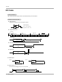
Installation and Operating Guide
Model Number | P42W34P | PLASMA DISPLAY PANEL
© Copyright 2003, Zenith Electronics Corporation.
Warning
Warning
WARNING
RISK OF ELECTRIC SHOCK
DO NOT OPEN
WARNING:
TO REDUCE THE RISK OF ELECTRIC SHOCK DO NOT REMOVE COVER (OR BACK). NO USER
SERVICEABLE PARTS INSIDE. REFER TO QUALIFIED SERVICE PERSONNEL.
The lightning flash with arrowhead symbol, within an equilateral triangle, is intended to alert the user to
the presence of uninsulated “dangerous voltage” within the product’s enclosure that may be of sufficient magnitude to constitute a risk of electric shock to persons.
The exclamation point within an equilateral triangle is intended to alert the user to the presence of
important operating and maintenance (servicing) instructions in the literature accompanying the appliance.
WARNING:
TO PREVENT FIRE OR SHOCK HAZARDS, DO NOT EXPOSE THIS PRODUCT TO RAIN OR MOISTURE.
FCC NOTICE
• A Class B digital device
This equipment has been tested and found to comply with the limits for a Class B digital device, pursuant to Part
15 of the FCC Rules. These limits are designed to provide reasonable protection against harmful interference in
a residential installation. This equipment generates, uses and can radiate radio frequency energy and, if not
installed and used in accordance with the instructions, may cause harmful interference to radio communications.
However, there is no guarantee that interference will not occur in a particular installation. If this equipment does
cause harmful interference to radio or television reception, which can be determined by turning the equipment off
and on, the user is encouraged to try to correct the interference by one or more of the following measures:
- Reorient or relocate the receiving antenna.
- Increase the separation between the equipment and receiver.
- Connect the equipment into an outlet on a circuit different from that to which the receiver is connected.
- Consult the dealer or an experienced radio/TV technician for help.
• Any changes or modifications not expressly approved by the party responsible for compliance could void the user’s authority to operate the equipment.
CAUTION:
Do not attempt to modify this product in any way without written authorization from Zenith Electronics
Corporation. Unauthorized modification could void the user’s authority to operate this product.
COMPLIANCE:
The responsible party for this product’s compliance is:
Zenith Electronics Corporation
2000 Millbrook Drive
Lincolnshire, Il 60069, USA
Phone: 1-847-941-8000
WARNING
TO REDUCE THE RISK OF FIRE AND ELECTRIC SHOCK, DO NOT EXPOSE THIS PRODUCT TO
RAIN OR MOISTURE.
2 Plasma Display
Safety Instructions
Safety Instructions
Important safeguards for you and your new product
Your product has been manufactured and tested with your safety in mind. However, improper use can result in potential electrical shock or fire hazards. To avoid defeating the safeguards that have been built into your new product, please read and
observe the following safety points when installing and using your new product, and save them for future reference.
Observing the simple precautions discussed in this booklet can help you get many years of enjoyment and safe operation
that are built into your new product.
This product complies with all applicable U.S. Federal safety requirements, and those of the Canadian Standards
Association.
1. Read Instructions
All the safety and operating instructions should be read
before the product is operated.
9. Attachments
Do not use attachments not recommended by the product
manufacturer as they may cause hazards.
2. Follow Instructions
All operating and use instructions should be followed.
10. Ventilation
Slots and openings in the cabinet are provided for ventilation
and to ensure reliable operation of the product and to protect
it from overheating, and these openings must not be blocked
or covered. The openings should never be blocked by placing the product on a bed, sofa, rug, or other similar surface.
This product should not be placed in a built-in installation
such as a bookcase or rack unless proper ventilation is provided or the manufacturer’s instructions have been adhered
to.
3. Retain Instructions
The safety and operating instructions should be retained for
future reference.
4. Heed Warnings
All warnings on the product and in the operating instructions
should be adhered to.
5. Cleaning
Unplug this product from the wall outlet before cleaning. Do
not use liquid cleaners or aerosol cleaners. Use a damp
cloth for cleaning.
6. Water and Moisture
Do not use this product near water, for example, near a bath
tub, wash bowl, kitchen sink, or laundry tub, in a wet basement, or near a swimming pool.
7. Accessories, Carts, and Stands
Do not place this product on a slippery or tilted surface, or on
an unstable cart, stand, tripod, bracket, or table. The product
may slide or fall, causing serious injury to a child or adult,
and serious damage to the product. Use only with a cart,
stand, tripod, bracket, or table recommended by the manufacturer, or sold with the product. Any mounting of the product should follow the manufacturer’s instructions, and should
use a mounting accessory recommended by the manufacturer.
8. Transporting Product
A product and cart combination should be moved with care.
Quick stops, excessive force, and uneven surfaces may
cause the product and cart combination to overturn.
11. Power Sources
This product should be operated only from the type of power
source indicated on the marking label. If you are not sure of
the type of power supply to your home, consult your product
dealer or local power company. For products intended to
operate from battery power, or other sources, refer to the
operating instructions.
12. Power-Cord Polarization
This product is equipped with a three-wire grounding type
plug, a plug having a third (grounding) pin. This plug will only
fit into the grounding-type power outlet. This is a safety feature. If you are unable to insert the plug into the outlet, contact your electrician to replace your obsolete outlet. Do not
defeat the safety purpose of the grounding-type plug.
13. Power-Cord Protection
Power-supply cords should be routed so that they are not
likely to be walked on or pinched by items placed upon or
against them, paying particular attention to cords at plugs,
convenience receptacles, and the point where they exit from
the product.
PORTABLE CART WARNING
Owner’s Manual 3
Safety Instructions
Safety Instructions continued
14. Outdoor Antenna Grounding
If an outside antenna or cable system is connected to the
product, be sure the antenna or cable system is grounded so
as to provide some protection against voltage surges and
built-up static charges. Article 810 of the National Electrical
Code (U.S.A.), ANSI/ NFPA 70 provides information with
regard to proper grounding of the mast and supporting structure, grounding of the lead-in wire to an antenna discharge
unit, size of grounding conductors, location of antenna-discharge unit, connection to grounding electrodes, and
requirements for the grounding electrode.
Example of Grounding According to National
Electrical Code Instructions
Ground Clamp
Antenna Lead in Wire
Antenna Discharge Unit
(NEC Section 810-20)
Electric Service
Equipment
Grounding Conductor
(NEC Section 810-21)
Ground Clamps
Power Service Grounding
Electrode System (NEC
Art 250, Part H)
NEC - National Electrical Code
15. Lightning
For added protection for this product (receiver) during a lightning storm, or when it is left unattended and unused for long
periods of time, unplug it from the wall outlet and disconnect
the antenna or cable system. This will prevent damage to the
product due to lightning and power-line surges.
16. Power Lines
An outside antenna system should not be located in the
vicinity of overhead power lines or other electric light or
power circuits, or where it can fall into such power lines or
circuits. When installing an outside antenna system, extreme
care should be taken to keep from touching such power lines
or circuits as contact with them might be fatal.
17. Overloading
Do not overload wall outlets and extension cords as this can
result in a risk of fire or electric shock.
18. Object and Liquid Entry
Never push objects of any kind into this product through
openings as they may touch dangerous voltage points or
short-out parts that could result in a fire or electric shock.
Never spill liquid of any kind on the product.
4 Plasma Display
19. Servicing
Do not attempt to service this product yourself as opening or
removing covers may expose you to dangerous voltage or
other hazards. Refer all servicing to qualified service personnel.
20. Damage Requiring Service
Unplug this product from the wall outlet and refer servicing to
qualified service personnel under the following conditions:
a. If the power-supply cord or plug is damaged.
b. If liquid has been spilled, or objects have fallen into the
product.
c. If the product has been exposed to rain or water.
d. If the product does not operate normally by following the
operating instructions. Adjust only those controls that are
covered by the operating instructions as an improper
adjustment of other controls may result in damage and
will often require extensive work by a qualified technician
to restore the product to its normal operation.
e. If the product has been dropped or the cabinet has been
damaged.
f. If the product exhibits a distinct change in performance.
21. Replacement Parts
When replacement parts are required, be sure the service
technician has used replacement parts specified by the manufacturer or have the same characteristics as the original
part. Unauthorized substitutions may result in fire, electric
shock, or other hazards.
22. Safety Check
Upon completion of any service or repairs to this product,
ask the service technician to perform safety checks to determine that the product is in proper operating condition.
23. Wall or Ceiling Mounting
The product should be mounted to a wall or ceiling only as
recommended by the manufacturer. The product may slide
or fall, causing serious injury to a child or adult, and serious
damage to the product.
24. Heat
The product should be situated away from heat sources
such as radiators, heat registers, stoves, or other products
(including amplifiers) that produce heat.
Contents
Contents
Warnings . . . . . . . . . . . . . . . . . . . . . . . . . . . . . . . . . . . . .2
Safety Instructions . . . . . . . . . . . . . . . . . . . . . . . . . . . . .3~4
Introduction
Controls and Connection Options . . . . . . . . . . . .7
Remote Control Key Functions . . . . . . . . . . . . . .8
Installation
Installation Instruction . . . . . . . . . . . . . . . . . . . .9~10
External Equipment Connections . . . . . . . . . .11~14
VCR Setup . . . . . . . . . . . . . . . . . . . . . . . . . . . .11
Cable TV Setup . . . . . . . . . . . . . . . . . . . . . . . .11
External A/V Source Setup . . . . . . . . . . . . . . . .12
DVD Setup . . . . . . . . . . . . . . . . . . . . . . . . . . . .12
DTV Setup . . . . . . . . . . . . . . . . . . . . . . . . . . . .12
PC Setup . . . . . . . . . . . . . . . . . . . . . . . . . .13~14
Operation
Turning on the Monitor . . . . . . . . . . . . . . . . . . . . .15
Menu Language Selection . . . . . . . . . . . . . . . . . .15
Picture Menu Options
APC (Auto Picture Control) . . . . . . . . . . . . . . . .16
Manual Picture Control . . . . . . . . . . . . . . . . . . .16
Auto Color Temperature Control . . . . . . . . . . . .16
Manual Color Temperature Control . . . . . . . . . .16
Sound Menu Options
DASP (Digital Auto Sound Processing) . . . . . . .17
Manual Sound Control . . . . . . . . . . . . . . . . . . .17
AVL (Auto Volume Leveler) . . . . . . . . . . . . . . . .17
Timer Menu Options
Clock Setup . . . . . . . . . . . . . . . . . . . . . . . . . . .18
On/Off Timers Setup . . . . . . . . . . . . . . . . . . . . .18
Auto Off . . . . . . . . . . . . . . . . . . . . . . . . . . . . . .18
Sleep Timer . . . . . . . . . . . . . . . . . . . . . . . . . . .18
Special Menu Options
Key Lock . . . . . . . . . . . . . . . . . . . . . . . . . . . . .19
ISM (Image Sticking Minimization) Method . . . .19
Low power . . . . . . . . . . . . . . . . . . . . . . . . . . . .19
Menu Rotation For Vertical Viewing . . . . . . . . . .20
Screen Menu Options
Auto Adjustment . . . . . . . . . . . . . . . . . . . . . . . .21
Setting Picture Format . . . . . . . . . . . . . . . . . . .21
Picture Size Zoom . . . . . . . . . . . . . . . . . . . . . .21
Adjusting Horizontal/Vertical Position . . . . . . . .22
Manual Configure . . . . . . . . . . . . . . . . . . . . . . .22
Screen Adjustments . . . . . . . . . . . . . . . . . . . . .22
Initializing . . . . . . . . . . . . . . . . . . . . . . . . . . . . .22
Luminance Noise Reduction . . . . . . . . . . . . . . .23
Selecting Wide VGA mode . . . . . . . . . . . . . . . .23
Split Zoom . . . . . . . . . . . . . . . . . . . . . . . . . . . .23
PIP (Picture In Picture) Feature
Watching PIP . . . . . . . . . . . . . . . . . . . . . . . . . .24
Swapping PIP . . . . . . . . . . . . . . . . . . . . . . . . . .24
Moving PIP . . . . . . . . . . . . . . . . . . . . . . . . . . . .24
Selecting a Input Signal Source for PIP . . . . . . .24
PIP Aspect Ratio . . . . . . . . . . . . . . . . . . . . . . . .24
Double Window Setup Options
Watching Double Window . . . . . . . . . . . . . . . . .25
Sub Picture Size Adjustment . . . . . . . . . . . . . . .25
Swapping the Double Window . . . . . . . . . . . . .25
Selecting a Source for the Double Window . . . .25
External Control Device Setup . . . . . . . . . . . . . . . .26~31
IR Code
. . . . . . . . . . . . . . . . . . . . . . . . . . . . . . . . .32~33
Troubleshooting Checklist . . . . . . . . . . . . . . . . . . . . . .34
Maintenance . . . . . . . . . . . . . . . . . . . . . . . . . . . . . . . . .35
Specifications . . . . . . . . . . . . . . . . . . . . . . . . . . . . . . . .35
After reading this manual, keep it handy for future reference.
Owner’s Manual 5
Introduction
Introduction
What is a Plasma Display Panel (PDP)?
If voltage is applied to gas within glass panels, ultraviolet rays are produced and fused with a fluorescent substance. At that
instant, light is emitted. A Plasma Display is a next generation flat Display using this phenomenon.
160° - Wide angle range of vision
Your flat panel plasma screen offers an exceptionally broad viewing angle -- over 160 degrees. This means that the display is
clear and visible to viewers anywhere in the room.
Wide Screen
The screen of the Plasma Display is 42" so wide that your viewing experience is as if you are in a theater.
Multimedia
Connect your plasma display to a PC and you can use it for conferencing, games, and internet browsing. The Picture-in-Picture
feature allows you to view your PC and video images simultaneously.
Versatile
The light weight and thin size makes it easy to install your plasma display in a variety of locations where conventional TVs will not
fit.
The PDP Manufacturing Process: Why minute colored dots may be present on the PDP screen
The PDP (Plasma Display Panel) which is the display device of this product is composed of 0.9 to 2.2 million cells. A few cell
defects will normally occur in the PDP manufacturing process. Several minute colored dots visible on the screen should be acceptable. This also occurs in other PDP manufacturers' products and the tiny dots appearing does not mean that this PDP is defective.
Thus a few cell defects are not sufficient cause for the PDP to be exchanged or returned. Our production technology is designed
to minimize cell defects during the manufacture and operation of this product.
Cooling Fan Noise
In the same way that a fan is used in a PC computer to keep the CPU (Central Processing Unit) cool, the PDP is equipped with
cooling fans to cool the Monitor and improve its reliability. Therefore, a certain level of noise could occur while the fans are operating and cooling the PDP.
The fan noise doesn't have any negative effect on the PDP's efficiency or reliability. The noise from these fans is normal during the
operation of this product. We hope you understand that a certain level of noise from the cooling fans is acceptable and is not sufficient cause for the PDP to be exchanged or returned.
6 Plasma Display
Introduction
Controls
Front Panel Controls
- This is a simplified representation of front panel.
Here shown may be somewhat different from your monitor.
INPUT
SELECT
ON/OFF
MENU
VOL.
E, D
Main Power Button
INPUT SELECT Button
Buttons
VOLUME (F,G) Buttons
MENU Button
Remote Control Sensor
Power Standby Indicator
Illuminates red in standby mode,
Illuminates green when the
Monitor is turned on
Connection Options
Back Connection Panel
- Connection panels shown may be somewhat different from your monitor.
R AUDIO L
( )L ( )
( )R( )
EXTERNAL SPEAKER
1
RS-232C INPUT
(CONTROL/SERVICE)
2
DVI INPUT
RGB INPUT
AUDIO INPUT
3
RGB OUTPUT
EXPANDED
INPUT
4
5
1. EXTERNAL SPEAKER (8 ohm output)
Connect to optional external speaker(s).
* For further information, refer to ‘Speaker & Speaker
Stand’ manual.
2. RS-232C INPUT (CONTROL/SERVICE) PORT
Connect to the RS-232C port on a PC.
3. DVI (Digital Visual Interface) INPUT/
RGB INPUT/AUDIO INPUT JACKS
Connect the monitor output connector of a PC to the appropriate input port.
4. RGB OUTPUT JACKS
You can watch the RGB signal on another monitor, connect
RGB OUTPUT to another monitor’s PC input port.
5. EXPANDED INPUT
AUDIO INPUT
Y
PB
PR
R AUDIO L (MONO)
COMPONENT INPUT REMOTE S-VIDEO
CONTROL
6
7
VIDEO
INPUT
8
AUDIO INPUT
AC INPUT
9
6. COMPONENT INPUT/AUDIO INPUT JACKS
Connect a component video/audio device to these jacks.
7. REMOTE CONTROL
Connect your wired remote control to the remote control
port on the Monitor.
8. S-VIDEO INPUT
Connect S-Video out from an S-VIDEO VCR to the S-VIDEO
input.
AUDIO/VIDEO INPUT JACKS
Connect audio/video out from external equipment to these
jacks.
9. POWER CORD SOCKET
This Monitor operates on an AC power. The voltage is indicated on the Specifications page. Never attempt to operate
the Monitor on DC power.
Owner’s Manual 7
Introduction
Remote Control Key Functions
- When using the remote control, aim it at the remote control sensor on the monitor.
- Under certain conditions such as if the remote IR signal is interrupted, the remote control may not function. Press the key again
as necessary.
POWER
Switches the monitor between
ON and STANDBY.
INPUT SELECT
Selects source: Video, S-Video,
Component, RGB, or DVI mode.
MULTIMEDIA
Selects: Component, RGB, or DVI
mode.
APC
Adjusts the factory preset picture
according to the room.
ARC
Changes the picture format.
PIP
Switches the sub picture on and off.
POWER
MULTIMEDIA
INPUT SELECT
APC
DASP
ARC
SLEEP
PIP
DW
SWAP
PIP INPUT
MENU
SWAP
Exchanges main and sub picture
images.
DASP
Selects the sound appropriate to
your viewing program character:
Flat, Music, Movie, Sports, or
VOL
CH
ENTER
MUTE
SPLIT ZOOM
Enlarge the screen with regular
ration.
ENTER
1
2
3
4
5
6
7
8
9
WIN.POSITION
0
WIN.SIZE
SPLIT ZOOM
ZOOM -
ZOOM +
A.PROG MEMORY/ERASE PIP CH
Not functional
PIP INPUT
Selects the input mode for the sub
picture.
MUTE
Switches the sound on or off.
CH
WIN.POSITION
Moves the sub picture.
DW (Double Window)
Selects Double Window mode.
VOL
MENU
Displays on screen menus.
Exits the current menu.
NUMBER buttons
User.
SLEEP
Sets the Sleep Timer.
CAPTION
FAV CH
MTS
POWER
STOP
REW
PIP CH
P/STILL
REC
PLAY
FF
CH D / E (Channel button)
Selects menu options.
VOL F / G (Volume button)
Increases/decreases sound level.
Adjusts menu settings.
WIN. SIZE
Adjusts the sub picture size.
ZOOM-/ZOOM+
Enlarges or reduces the main picture
size.
VCR BUTTONS
Control some video cassette
recorders.
Installing Batteries
• Open the battery compartment cover on the back side and
insert the batteries with correct polarity.
• Install two 1.5V batteries of AAA type. Don’t mix used batteries
with new batteries.
8 Plasma Display
Installation
Installation
Ensure that the following accessories are included with your plasma display. If an accessory is missing, please contact the dealer
where you purchased the product.
POWER
SLEEP
INPUT SELECT
APC
DASP
ARC
PIP ARC
PIP
TWIN PICTURE
SUB INPUT
SWAP
MENU
MUTE
VOL
OK
1
2
4
5
7
8
VOL
3
6
9
0
1.5V
1.5V
Owner’s Manual
D-sub 15 pin Cable
POWER
STOP
P/STILL
REW
PLAY
FF
REC
WIN.SIZE WIN.POSITION SPLIT ZOOM
ZOOM -
Batteries
BNC-RCA Adapter
ZOOM +
Remote Control
DVI-D Cable
Power Cord
Installation Instructions
• The Monitor can be installed in various ways such as on a wall, or on a desktop etc.
• The plasma display is designed to be mounted horizontally or vertically. The speakers depicted are optional.
GROUNDING
Power
Supply
Ensure that you connect the grounding / earth wire to prevent possible
electric shock. If grounding methods are not possible, have a qualified
electrician install a separate circuit breaker. Do not try to ground the
unit by connecting it to telephone wires, lightening rods, or gas pipes.
yyyyyy
;;;;;;
;;;;;;
yyyyyy
;;;;;;
yyyyyy
;;;;;;
yyyyyy
;;;;;;
yyyyyy
Short-circuit
Breaker
Wall Mount: Horizontal installation
For proper ventilation, allow a clearance of 4” on each
side and 2” from the wall. Detailed installation instructions are included from your dealer in the optional Wall
Mounting Bracket Installation and Setup Guide.
2 inches
4 inches
4 inches
4 inches
4 inches
Owner’s Manual 9
Installation
Installation Instructions continued
Desktop Pedestal Installation
For proper ventilation, allow a clearance of 4” on each
side and the top, 2.36” on the bottom, and 2” from the
wall. Detailed installation instructions are included in the
optional Desktop Stand Installation and Setup Guide, see
your dealer.
2 inches
4 inches
4 inches
4 inches
2.36 inches
Wall Mount: Vertical
Vertical installation
Detailed installation instructions are included in the
optional Vertical Wall Mounting Bracket Installation and
Setup Guide, see your dealer.
NOTE: When installing the monitor vertically, the front
panel controls must be in the left side position.
When installing the monitor vertically, you
have to change the OSD (On Screen Display)
display mode so that the menus will appear
correctly and also to protect the monitor from
overheating (Refer to P. 20).
10 Plasma Display
Installation
External Equipment Connections
NOTE: All cables shown are not included with the plasma display.
VCR Setup
- To avoid picture noise (interference), leave an adequate distance between the VCR and Monitor
- Use the ISM Method feature to avoid having a fixed image remain on the screen for a long period of time. Typically a frozen still
picture from a VCR. If the 4:3 picture format is used; the fixed image may remain visible on the screen.
How to connect
1. Connect the provided BNC-RCA adapter to the monitor’s
VIDEO INPUT.
2. Connect the audio and video cables from the VCR's output
jacks to the monitor input jacks, as shown in the figure. When
connecting the monitor to a VCR, match the jack colors: (Video
= yellow, Audio Left = white, and Audio Right = red).
R AUDIO L
AUDIO INPUT
Y
PB
PR
R AUDIO L (MONO)
COMPONENT INPUT REMOTE S-VIDEO
CONTROL
VIDEO
INPUT
AUDIO INPUT
VCR: Connect the video output cable from the VCR to the
VIDEO input on the monitor.
S-VIDEO VCR: Connect the S-Video output cable from the
VCR to the S-VIDEO input. (Note that S-Video yields higher
quality video).
How to use
1. Insert a video tape into the VCR and press PLAY on the VCR.
(Refer to the VCR owner’s manual.)
2. Use the INPUT SELECT button on the remote control to select
Video.
(If connected to S-VIDEO, select the S-Video external input
source.)
S-VIDEO
OUT
(R) AUDIO (L)
VIDEO
IN
VCR
Cable TV Setup
- After subscribing to a cable TV service from a local provider and installing a converter, you can watch cable TV programming.
The monitor cannot display TV programming unless a TV tuner device or cable TV converter box is connected to the Monitor.
- For further information regarding cable TV service, contact your local cable TV service provider(s).
How to connect
1. Connect the provided BNC-RCA adapter to the monitor’s
VIDEO INPUT.
2. Connect the audio and video cables from the cable box's output jacks to the monitor input jacks, as shown in the figure.
When connecting the monitor to a cable TV, match the jack
colors (Video = yellow, Audio Left = white, and Audio Right =
red).
R AUDIO L
AUDIO INPUT
Y
PB
PR
R AUDIO L (MONO)
COMPONENT INPUT REMOTE S-VIDEO
CONTROL
VIDEO
INPUT
AUDIO INPUT
How to use
1. Use the INPUT SELECT button on the remote control to
select Video.
2. Select your desired channel with the cable box remote control.
(R) AUDIO (L)
VIDEO
TV
VCR
RF
Cable
Cable Box
Owner’s Manual 11
Installation
External A/V Source Setup
How to connect
1. Connect the provided BNC-RCA adapter to the monitor’s
VIDEO INPUT.
2. Connect the audio and video cables from the external
equipment's output jacks to the monitor input jacks, as
shown in the figure. When connecting the monitor to external equipment, match the jack colors (Video = yellow, Audio
Left = white, and Audio Right = red).
R AUDIO L
AUDIO INPUT
Y
PB
PR
R AUDIO L (MONO)
S-VIDEO
COMPONENT INPUT REMOTE
CONTROL
VIDEO
INPUT
AUDIO INPUT
How to use
Camcorder
1. Use the INPUT SELECT button on the remote control to
select Video.
2. Operate the corresponding external equipment. Refer to
external equipment operating guide.
Video game set
R
AUDIO
VIDEO
L
DVD Setup
How to connect
R AUDIO L
AUDIO INPUT
Y
PB
PR
1. Connect the DVD video outputs to the COMPONENT (Y, PB, PR)
INPUT jacks and connect the DVD audio outputs to the AUDIO
INPUT jacks on the monitor, as shown in the figure.
2. If your DVD only has an S-Video output jack, connect this to the
S-VIDEO input on the monitor and connect the DVD audio outputs
to the AUDIO INPUT jacks, as shown in the figure.
R AUDIO L (MONO)
COMPONENT INPUT REMOTE S-VIDEO
CONTROL
VIDEO
INPUT
AUDIO INPUT
How to use
1. Turn on the DVD player, insert a DVD.
2. Use the INPUT SELECT button on the remote control to select
Component. (If connected to S-VIDEO, select the S-Video external input source.)
3. Refer to the DVD player's manual for operating instructions.
or
(R) AUDIO (L)
B
(R) AUDIO (L)
R
S-VIDEO
• Component Input ports
To get better picture quality, connect a DVD player to the component input ports as shown below.
Component ports of the
Monitor
DVD
Video output ports
of DVD player
PR
Y
PB
Y
Y
Y
Y
Pr
Pb
B-Y R-Y
Cb Cr
PB PR
DTV Setup
- To watch digitally broadcast programs, purchase and
connect a digital set-top box.
- This monitor supports HDCP (High-bandwidth Digital
Contents Protection) protocol for DTV
(480p,720p,1080i) modes.
R AUDIO L
DVI INPUT
RGB INPUT
AUDIO INPUT
RGB OUTPUT
EXPANDED
INPUT
AUDIO INPUT
Y
PB
PR
R AUDIO L (MONO)
COMPONENT INPUT REMOTE S-VIDEO
CONTROL
VIDEO
INPUT
AUDIO INPUT
How to connect
1. Use the monitor’s COMPONENT (Y, PB, PR) INPUT,
RGB or DVI jack for video connections, depending on
your set-top box connector. Then, make the corresponding audio connections.
How to use
1. Turn on the digital set-top box. (Refer to the owner’s
manual for the digital set-top box.)
2. Use INPUT SELECT on the remote control to select
Component, RGB or DVI.
or
DVI-DTV OUTPUT
(R) AUDIO (L)
or
RGB-DTV OUTPUT
(R) AUDIO (L)
Digital Set-top Box
12 Plasma Display
(R) AUDIO (L)
B
R
Installation
PC Setup
- This Plasma display provides Plug and Play capability, meaning that the PC adjusts automatically to its settings. The monitor
sends configuration information (EDID) to the PC using the Video Electronics Standard Association (VESA) Display Data
Channel (DDC) protocol.
How to connect
1. To get the best picture quality, adjust the PC
graphics card to 800x600, 60Hz.
2. Use the monitor’s RGB INPUT or DVI (Digital
Visual Interface) INPUT port for video connections,
depending on your PC connector.
If the graphic card on the PC does not output analog and digital RGB simultaneously, connect only
one of both RGB INPUT or DVI INPUT to display
the PC image on the monitor.
If the graphic card on the PC does output analog
and digital RGB simultaneously, set the monitor to
either RGB or DVI; (the other mode is set to Plug
and Play automatically by the monitor.)
3. Then, make the corresponding audio connections.
If using a sound card, adjust the PC sound as
required.
( )R( )
( )L ( )
EXTERNAL SPEAKER
RS-232C INPUT
(CONTROL/SERVICE)
DVI INPUT
RGB INPUT
AUDIO INPUT
RGB OUTPUT
EXPANDED
INPUT
How to use
1. Turn on the PC and the monitor.
2. Turn on the display by pressing the POWER button on the monitor's remote control.
3. Use the INPUT SELECT button on the remote control to select RGB or DVI.
4. Check the image on your monitor. There may be noise associated with the resolution, vertical pattern, contrast or
brightness in PC mode. If noise is present, change the PC mode to another resolution, change the refresh rate to
another rate or adjust the brightness and contrast on the menu until the picture is clear. If the refresh rate of the PC
graphic card can not be changed, change the PC graphic card or consult the manufacturer of the PC graphic card.
NOTES
• Depending on the graphics card, DOS mode may not work if you use a DVI-I cable.
• Avoid keeping a fixed image on the monitor's screen for a long period of time. The fixed image may become permanently imprinted on the screen. Use the Orbiter screen saver when possible.
• The synchronization input form for Horizontal and Vertical frequencies is separate.
Owner’s Manual 13
Installation
Monitor Display Specifications (RGB-PC /DVI-PC Mode)
Resolution
640x350
720x400
640x480
848x480
852x480
14 Plasma Display
Horizontal
Vertical
Frequency(KHz) Frequency(Hz)
31.468
70.09
37.861
85.08
31.469
70.08
37.927
31.469
Resolution
Horizontal
Vertical
Frequency(KHz) Frequency(Hz)
35.156
56.25
37.879
60.31
48.077
72.18
85.03
46.875
75.00
59.94
53.674
85.06
49.725
74.55
48.363
60.00
56.476
70.06
60.023
75.02
54.348
60.05
63.995
70.01
67.500
75.00
1152x870
68.681
75.06
800x600
832x624
35.000
66.66
37.861
72.80
37.500
75.00
43.269
85.00
31.500
60.00
35.00
70.00
37.500
75.00
31.500
60.00
35.000
70.00
1280x960
60.000
60.00
37.500
75.00
1280x1024
63.981
60.02
1024x768
1152x864
Operation
Operation
Turning on the Monitor
Turning on the Monitor just after installation
1. Connect power cord correctly.
2. Press the
ON/OFF button on the Monitor. At this moment, the Monitor is switched to standby
mode. Press the INPUT SELECT button on the Monitor or press the POWER, INPUT SELECT,
MULTIMEDIA button on the remote control to switch the Monitor on.
Turning on the Monitor (power cord is still connected)
1. If the Monitor was turned off with the
• Press the
ON/OFF button on the Monitor
ON/OFF button on the Monitor to turn the Monitor on.
2. If the Monitor was turned off with the remote control and the
ON/OFF button on the Monitor
• Press the
ON/OFF button on the Monitor and then press the INPUT SELECT button on the
Monitor. Or, on the remote control, press POWER, INPUT SELECT, or MULTIMEDIA to turn the
Monitor on.
Menu Language Selection
- The menus can be shown on the screen in the selected language. First select your language.
1. Press the MENU button and then use
2. Press the G button and then use D /
E
D
/
E
button to select the SPECIAL menu.
button to select Language.
3. Press the G button and then use D / E button to select your desired language.
From this point on, the on-screen menus will be shown in the language of your
choice.
SPECIAL
Language
G
English
Key lock
Español
ISM Method
Français
Low power
Set ID
Caption / Text
4. Press the ENTER button to save.
Captions
OSD Rotate
MENU
Prev.
Owner’s Manual 15
Operation
Picture Menu Options
- Each adjustment for the Picture menu options doesn’t effect other input sources. Readjust Picture
menu options for each of the following sources.
• RGB (PC) / DVI (PC),
• RGB (DTV) / DVI (DTV) / Component (480p, 720p, 1080i)
• Video / S-Video / Component (480i)
APC (Auto Picture Control)
- APC adjusts the Monitor for the best picture appearance.
- When adjusting picture options (contrast, brightness, color, sharpness and tint) manually, APC automatically
changes to User.
1. Press the APC button repeatedly to select the picture appearance setup option as shown below.
Optimum
Soft
User
Clear
• You can also adjust APC in the PICTURE menu.
• Clear, Optimum, and Soft are preset for good picture quality at the factory and cannot be changed.
Manual Picture Control ( User option)
- You can adjust picture contrast, brightness, color, sharpness, and tint to the levels
you prefer.
PICTURE
APC
ACC
Color temp.
1. Press the MENU button and then use
D /E
button to select the PICTURE menu.
2. Press the G button and then use D / E button to select the desired picture option
(Contrast, Brightness, Color, Sharpness, Tint).
3. Press the G button and then use
F /G
button to make appropriate adjustments.
4. Press the ENTER button to save.
Contrast
80
G
Brightness 60
Color
50
Sharpness 50
Tint
0
MENU
Prev.
Auto Color Temperature Control
- To initialize values (reset to default settings), select the Normal option.
- When adjusting color temperature options (red, green, or blue) manually, ACC
automatically changes to User.
PICTURE
APC
G
ACC
1. Press the MENU button and then use
2. Press the
G
button and then use
D /E
D /E
button to select the PICTURE menu.
button to select ACC .
3. Press the G button and then use D / E button to select either Normal (Default),
Cool (Preset), Warm (Preset) or User (Manual Adjustment).
4. Press the ENTER button to save.
Normal
Cool
Color temp.
Contrast
80
Warm
Brightness
60
User
Color
50
Sharpness
50
Tint
0
MENU
Prev.
Manual Color Temperature Control ( User option)
- You can adjust red, green, or blue to any color temperature you prefer.
PICTURE
1. Press the MENU button and then use
D /E
button to select the PICTURE menu.
APC
ACC
2. Press the
G
button and then use
3. Press the
G
button and then use D
4. Use the
F /G
D /E
/E
button to select Color temp .
button to select Red, Green or Blue.
button to make appropriate adjustments.
• The adjustment range of Red, Green, and Blue is -20 ~ +20.
5. Press the ENTER button to save.
16 Plasma Display
G
Red
0
80
Green
0
Brightness
60
Blue
0
Color
50
Sharpness
50
Color temp.
Contrast
Tint
MENU
0
Prev.
Operation
Sound Menu Options
DASP (Digital Auto Sound Processing)
- This function lets you enjoy the best sound without any special adjustment because the Monitor has the appropriate sound option based on the program content.
- When adjusting sound options (treble, bass, and balance) manually, DASP automatically changes to User.
1. Press the DASP button repeatedly to select the appropriate sound setup as shown below.
Flat
Music
Movie
Sports
User
• You can also adjust DASP in the SOUND menu.
• Flat, Music, Movie and Sports are preset for good sound quality at the factory and cannot be
changed.
Manual Sound Control ( User option)
- You can adjust sound treble, bass, and balance to the levels you prefer.
1. Press the MENU button and then use D
/E
2. Press the G button and then use
(Balance, Treble, Bass).
button to select the desired sound option
3. Press the
G
button and then use
D /E
button to select the SOUND menu.
SOUND
DASP
AVL
F /G
button to make appropriate adjustments.
4. Press the ENTER button to save.
Balance
0
Treble
50
Bass
50
MENU
G
Prev.
AVL (Auto Volume
Volume Leveler)
- AVL maintains an equal sound level; even if you change channels.
1. Press the MENU button and then use
D /E
button to select the SOUND menu.
2. Press the
G
button and then use
D /E
button to select AVL.
3. Press the
G
button and then use
D /E
button to select On or Off.
4. Press the ENTER button to save.
SOUND
DASP
G
AVL
Balance
0
Treble
50
Bass
50
MENU
On
Off
Prev.
Owner’s Manual 17
Operation
T imer Menu Options
Clock Setup
- If current time setting is erased by a power failure, if TV is unplugged or if the monitor is turned off with
the
ON/OFF button on the monitor, reset the clock.
1. Press the MENU button and then use
D /E
button to select the TIMER menu.
TIMER
2. Press the
G
3. Press the
4. Press the
button and then use
D /E
button to select Clock.
G
button and then use
D /E
button to set the hour.
G
button and then use
D /E
button to set the minutes.
G
Clock
-- : --
Off timer
On timer
Auto off
5. Press the ENTER button to save.
MENU
Prev.
On/Off
On/Off Timers Setup
- Timer functions operate only if current time has been set.
- Off-Timer function overrides On-Timer function if they are set to the same time.
- The monitor must be in standby mode for the On-Timer to work.
1. Press the MENU button and then use
2. Press the
G
button and then use
D /E
D /E
TIMER
button to select the TIMER menu.
Clock
button to select Off timer or On timer.
Off timer
On timer
3. Press the G button and then use D / E button to select On.
• To cancel On/Off timer function, select Off.
G
button and then use
D /E
button to set the hour.
5. Press the
G
button and then use
D /E
button to set the minutes.
G
button and then use
On
Off
10 : 30
4. Press the
6. For only On timer function; Press the
sound level.
G
Auto off
Vol.
D /E
button to set
MENU
Prev.
7. Press the ENTER button to save.
Auto Off
Off
- If there is no input signal, the Monitor will turn off automatically after 10 minutes.
1. Press the MENU button and then use
D /E
2. Press the G button and then use
D /E
button to select Auto off.
3. Press the G button and then use
D /E
button to select On or Off.
TIMER
button to select the TIMER menu.
Clock
Off timer
On timer
Auto off
G
On
Off
4. Press the ENTER button to save.
MENU
Prev.
Sleep Timer
- The Sleep Timer turns the Monitor off at the preset time. Note that this setting is cleared when the monitor is turned off.
1. Press the SLEEP button repeatedly to select the number of minutes. First the
screen, followed by the following sleep timer options:
10, 20, 30, 60, 90, 120, 180, and 240 minutes.
zz
--- Min option appears on the
2. When the number of minutes you want is displayed on the screen, press the ENTER button. The timer begins to
count down from the number of minutes selected.
3. To check the remaining minutes before the monitor turns off, press the SLEEP or ENTER button once.
4. To cancel the Sleep Timer, press the SLEEP button repeatedly until
18 Plasma Display
30
Ch. TV 2
zz
--- Min appears.
Special Menu Options
Key Lock
- The monitor can be set up so that it can only be used with the remote control.
- This feature can be used to prevent unauthorized viewing by disabling the front panel controls.
- This Monitor is programmed to remember which option it was last set to even if you turn the monitor off.
1. Press the MENU button and then use
D /E
button to select the SPECIAL menu.
2. Press the
G
button and then use
D /E
button to select Key lock.
3. Press the
G
button and then use
D /E
button to select On or Off.
4. Press the ENTER button to save.
SPECIAL
Language
Key lock
On
G
Off
ISM Method
Low power
• With the KEY LOCK ON, the display ‘
button on the front panel is pressed.
W
Key lock’
appears on the screen if any
Set ID
Caption / Text
Captions
OSD Rotate
MENU
Prev.
ISM (Image Sticking Minimization) Method
- A frozen still picture from a PC/video game displayed on the screen for prolonged periods will result in a ghost
image remaining even when you change the image. Avoid allowing a fixed image to remain on the Monitor's
screen for a long period of time.
1. Press the MENU button and then use
2. Press the
G
D /E
button to select the SPECIAL menu.
button and then use
D /E
button to select ISM Method.
3. Press the G button and then use
wash, Orbiter, or Inversion.
D /E
button to select either Normal, White
SPECIAL
Language
Key lock
• Normal:
If image sticking is never a problem, ISM is not necessary - set to Normal.
• White wash
White Wash removes permanent images from the screen. Note: An excessive permanent image may be impossible to clear entirely with White Wash. To return to
normal viewing, press any button.
• Orbiter
Orbiter may help prevent ghost images. However, it is best not to allow any fixed
image to remain on the screen. To avoid a permanent image on the screen, the
screen will move every 1 minutes: Right → Right → Downside → Downside →
Left → Left → Upside → Upside.
• Inversion
Inversion will automatically invert the plasma display panel color every 30 minutes.
ISM Method
G
Normal
Low power
White wash
Set ID
Orbiter
Caption / Text
Inversion
Captions
OSD Rotate
MENU
Prev.
4. Press the ENTER button to save.
Low Power
- Low power reduces the plasma display power consumption.
1. Press the MENU button and then use
D /E
button to select the SPECIAL menu.
2. Press the
G
button and then use
D /E
button to select Low power.
3. Press the
G
button and then use
D /E
button to select On or Off.
SPECIAL
Language
Key lock
ISM Method
Low power
• When you select On, the screen darkens.
4. Press the ENTER button to save.
Set ID
G
On
Off
Caption / Text
Captions
OSD Rotate
MENU
Prev.
Owner’s Manual 19
Operation
Special Menu Options continued
Menu Rotation for Vertical
Vertical Viewing
Viewing
1. Press the MENU button and then use
2. Press the G button and then use D
D /E
button to select the SPECIAL menu.
/ E button to select OSD (On Screen Display)
Rotate.
3. Press the
SPECIAL
Language
Key lock
G
button and then use
D /E
button to select Normal or Rotate.
• Select Normal, if the monitor was installed horizontally.
• Select Rotate, if the monitor was installed vertically.
ISM Method
Low power
Set ID
Caption / Text
Captions
4. Press the ENTER button to save.
OSD Rotate
MENU
20 Plasma Display
Prev.
Normal
G
Rotate
Operation
Screen Menu Options
Auto Adjustment
-
RGB (PC) mode only; this function doesn’t work for RGB-DTV mode.
Automatically adjusts picture position and minimizes image shaking.
After adjustment, if the image is still not correct, your Monitor is functioning properly but needs further adjustment.
Auto config. and Manual config. are not active in DVI mode.
1. Press the MENU button and then use
D /E
2. Press the G button and then use
button to select Auto config..
D /E
button to select the SCREEN menu.
3. Press the G button to run Auto configure.
SCREEN
G
Auto config.
To set
ARC
Zoom in/out
• When Auto config. has finished, OK will be shown on screen.
• If the position of the image is still not correct, try Auto adjustment again.
4. In RGB (PC) mode, if the image needs to be adjusted more after using Auto config., you can make further adjustments with the Manual config. option.
Position
Manual config.
Screen adj.
Reset
VGA Mode
MENU
Prev.
Setting Picture Format
- Caution: If a 4:3 fixed image is on the screen for a long time, it may remain visible.
- Set every aspect ratio for RGB 480p, DVI 480p, Component 480i/480p, Video, and S-Video sources.
- Use 4:3, or 16:9 for other input sources.
1. Use the ARC button repeatedly to select the desired picture format. You can also adjust ARC in the SCREEN menu.
• 4:3
- Choose 4:3 when you want to view a picture with an original 4:3 aspect ratio, with gray bars appearing at both the
left and right sides.
• 16:9
- Choose 16:9 when you want to adjust the picture horizontally, in a linear proportion to fill the entire screen.
• Horizon
- Choose Horizon when you want to adjust the picture in a non-linear proportion, that is, more enlarged at both
sides, to create a spectacular view.
• Zoom
- Choose Zoom when you want to view the picture without any alteration. However, the top and bottom portions of
the picture will be cropped.
Picture Size Zoom
- When enlarging or reducing the picture, the image may become distorted.
1. Use ZOOM+/ZOOM- button to enlarge or reduce the picture size.
• Zoom adjustment range is 100~300.
2. Adjust the main picture position using the
enlarged picture mode.
Zoom out
100%
D /E /F /G
buttons while in the
F
D
E
G
Owner’s Manual 21
Operation
Screen Menu Options continued
Adjusting Horizontal/ Vertical
Vertical Position
- This function works in the following modes:
RGB-PC, RGB-DTV (480p,720p,1080i), COMPONENT (480p,720p,1080i).
SCREEN
Auto config.
ARC
1. Press the MENU button and then use
D /E
button to select the SCREEN menu.
Zoom in/out
Position
2. Press the
G
button and then use
D /E
3. Press the
G
button and then use
D /E /F /G
button to select Position.
button to adjust the position.
4. Press the ENTER button to save.
G
F
D
E
G
Manual config.
Screen adj.
Reset
VGA Mode
MENU
Prev.
Manual Configure (RGB-PC mode only)
- If the image still isn’t clear after auto adjustment and especially if characters are still jittery, adjust the picture
Phase manually.
- To correct the screen size, adjust Clock.
1. Press the MENU button and then use
D /E
2. Press the G button and then use
D /E
button to select Manual config..
3. Press the G button and then use
D /E
button to to select Phase or Clock.
4. Use the
F /G
button to select the SCREEN menu.
button to make appropriate adjustments.
SCREEN
Auto config.
ARC
Zoom in/out
Position
Manual config.
• The Phase adjustment range is 0 ~ 31.
• The Clock adjustment range is -50 ~ +50.
G
Screen adj.
Phase
0
Clock
0
Reset
5. Press the ENTER button to save.
VGA Mode
MENU
Prev.
Screen Adjustments (Video,
(Video, S-Video
S-Video and Component 480i mode only)
- Use this function to correct jittering or picture instability while viewing a video tape.
button to select the SCREEN menu.
1. Press the MENU button and then use
D /E
2. Press the G button and then use
D /E
button to select Screen adj..
3. Press the G button and then use
D /E
button to select TV or VCR.
• Select the VCR option if watching a VCR.
• Select the TV option for other equipment. (Except VCR)
SCREEN
Auto config.
ARC
Zoom in/out
Position
Manual config.
Screen adj.
4. Press the ENTER button to save.
G
TV
VCR
Reset
YNR
MENU
Prev.
Initializing (Reset to original factory value)
- This function operates in every mode.
- Use the Reset option to initialize the adjusted settings.
SCREEN
Auto config.
1. Press the MENU button and then use
D /E
2. Press the G button and then use
button to select Reset.
D /E
button to select the SCREEN menu.
3. Press the G button.
ARC
Zoom in/out
Position
Manual config.
Screen adj.
• You can initialize Zoom In/Out, Manual config., Position, Split zoom, PIP size, PIP
position and sub picture size for double window.
YNR
MENU
22 Plasma Display
G
Reset
Prev.
To set
Operation
Luminance Noise Reduction (Video,
(Video, S-Video
S-Video and Component 480i modes only)
- Use YNR to reduce the picture noise that may appear on the screen.
1. Press the MENU button and then use
2. Press the
G
button and then use
3. Press the G button and then use
D /E
D /E
D /E
button to select the SCREEN menu.
SCREEN
button to select YNR.
Auto config.
ARC
button to select On or Off.
Zoom in/out
4. Press the ENTER button to save.
Position
Manual config.
Screen adj.
Reset
On
G
YNR
MENU
Off
Prev.
Selecting W ide VGA mode (RGB-PC, DVI-PC mode only)
- To see a normal picture, match the resolution of RGB mode and selection of VGA mode.
1. Press the MENU button and then use
D /E
button to select the SCREEN menu.
2. Press the G button and then use
D /E
button to select VGA Mode.
3. Press the G button and then use
D /E
button to select the desired VGA resolution.
SCREEN
Auto config.
ARC
Zoom in/out
4. Press the ENTER button to save.
Position
Manual config.
Screen adj.
640x480
Reset
848x480
VGA Mode
MENU
G
852x480
Prev.
Split Zoom
-
Enlarges the picture proportionately correct.
Split Zoom can be used for all input sources.
In 2-Split Zoom mode, you can only move the image up or down.
If an image is enlarged, a section can be viewed without using Split Zoom.
Split Zoom is not available if OSD rotate is rotate.
1. Press the SPLIT ZOOM button repeatedly to select either 2, 4, or 9 Split Zoom.
2-Split zoom
9-Split zoom
4-Split zoom
1
▲
▼
1
2
▲
▼
1
4
4
◀▶
4
5
◀▶
7
2
5
8
3
6
9
▲
▼
◀▶
2. Press the number button corresponding to the section you wish to enlarge. you can move the enlarged screen
with using the D / E / F / G button.
Example of choosing 5.
9-Split zoom
1
4
7
2
5
8
3
6
9
Section 5 is enlarged to fill
the screen.
▲
▼
◀▶
Owner’s Manual 23
Operation
PIP (Picture-In-Picture) Feature
- PIP lets you view 2 different inputs pictures (sources) on your monitor screen at the same time. One source will be large, and
the other source will show a smaller inset image.
- You can also adjust the PIP features in the PIP/DW menu (Except Swap function).
Watching PIP
Swapping the PIP
Press the PIP button repeatedly to turn PIP on or off.
Press the SWAP button to exchange the main and sub pictures.
Component
Video
Component
Video
Video
Component
10 : 30
10 : 30
10 : 30
Main Picture
Sub Picture
Moving the PIP
Press the WIN.POSITION button.
Press the D / E / F / G button repeatedly until desired position is achieved.
The sub picture moves up/down/left/right.
You can also move the PIP position with Win.position in the PIP/DW menu.
Win.position
▲
◀
▶
▼
Selecting an Input Signal Source for the PIP
Use the PIP INPUT button to select the input source for the sub picture.
Available Sub Picture Sources
Main Picture Source
Video
S-Video
Component 480i
Component 480p/720p/1080i
RGB and DVI
S-Video, Component 480i/480p/720p/1080i, RGB and DVI
Video, Component 480i/480p/720p/1080i, RGB, and DVI
Video,S-Video, RGB, and DVI
Video and S-Video
Video, S-Video, and Component 480i,
PIP Aspect Ratio
- Press the WIN.SIZE button and then use
picture size.
F /G
button to change the sub
Win.size
F
G
- To watch 4: 3 or 16:9 aspect ratio for sub picture
PIP/DW
1. Press the MENU button and then use
D /E
button to select the PIP/DW menu.
2. Press the G button and then use
D /E
button to select PIP ARC.
3. Press the G button and then use
D /E
button to select 4:3 or 16:9.
Input
DW
PIP
4. Press the ENTER button to save.
PIP Input
Win. size
Win. position
PIP ARC
G
4:3
16 : 9
MENU
24 Plasma Display
Prev.
Operation
Double W indow Setup Options
- As the name suggests, this mode splits the screen into 2, allowing 2 picture sources to be shown on the monitor screen at the
same time. Each source is given half the screen.
Watching Double Window
Window
Press the DW button repeatedly to select one of the Double Window options.
DW 1
DW 2
Sub Picture Size Adjustment
Press the WIN.SIZE button.
• Use the F / G button to change the sub picture size.
• Using the Win.size function in Double Window mode, main and sub picture sizes are
changed simultaneously.
Using the Win.size function in PIP mode, sub picture size is changed.
• Win.position is not functional in Double Window mode.
Win.size
◀F
G▶
Swapping the Double Window
Window
Use the SWAP button to switch the main and sub pictures in Double Window mode.
Component
Video
10 : 30
Main Picture
Video
Component
10 : 30
Sub Picture
Selecting a Source for the Double Window
Window
Use the PIP INPUT button to select the input source for the sub picture. You can also select PIP Input in the PIP/DW menu.
Main Picture Source
Video
S-Video
Component 480i
Component 480p/720p/1080i
RGB and DVI
Available Sub Picture Sources
S-Video, Component 480i/480p/720p/1080i, RGB and DVI
Video, Component 480i/480p/720p/1080i, RGB, and DVI
Video,S-Video, RGB, and DVI
Video and S-Video
Video, S-Video, and Component 480i,
Owner’s Manual 25
External Control Device Setup
External Control Device Setup
- Connect the RS-232C input jack to an external control device (such as a computer or an A/V control system)
and control the Monitor’s functions externally.
- Connect the serial port of the control device to the RS-232C jack on the Monitor back panel.
- RS-232C connection cables are not supplied with the Monitor.
RS-232C Setup
( )R( )
R AUDIO L
( )L ( )
RS-232C INPUT
EXTERNAL SPEAKER
(CONTROL/SERVICE)
DVI INPUT
RGB INPUT
AUDIO INPUT
RGB OUTPUT
EXPANDED
INPUT
AUDIO INPUT
Y
PB
PR
R AUDIO L (MONO)
COMPONENT INPUT REMOTE S-VIDEO
CONTROL
VIDEO
INPUT
AUDIO INPUT
AC INPUT
PC
Type of Connector; D-Sub 9-Pin Male
No.
1
2
3
4
5
6
7
8
9
1
Pin Name
No connection
RXD (Receive data)
TXD (Transmit data)
DTR (DTE side ready)
GND
DSR (DCE side ready)
RTS (Ready to send)
CTS (Clear to send)
No Connection
5
9
6
RS-232C Configurations
3-Wire Configurations
(Not standard)
7-Wire Configurations
(Standard RS-232C cable)
PC
PDP
2
3
5
4
6
7
8
3
2
5
6
4
8
7
D-Sub 9
D-Sub 9
RXD
TXD
GND
DTR
DSR
RTS
CTS
26 Plasma Display
TXD
RXD
GND
DSR
DTR
CTS
RTS
RXD
TXD
GND
DTR
DSR
RTS
CTS
PC
PDP
2
3
5
4
6
7
8
3
2
5
4
6
7
8
D-Sub 9
D-Sub 9
TXD
RXD
GND
DTR
DSR
RTS
CTS
External Control Device Setup
Set ID
Use this function to specify a monitor ID number.
Refer to ‘Real Data Mapping 1’. See page 28.
SPECIAL
Language
1. Press the MENU button and then use
D /E
button to select the SPECIAL menu.
2. Press the G button and then use
button to select Set ID.
Key lock
ISM Method
D /E
Low power
G
3. Press the G button and then use F / G button to adjust Set ID to choose the desired
monitor ID number. The adjustment range of Set ID is 1 ~ 99.
Set ID
4. Press the ENTER button to save.
OSD Rotate
1
Caption / Text
Captions
MENU
Prev.
Communication Parameters
• Baud rate : 115200 bps (UART)
• Data length : 8 bits
• Parity : None
• Stop bit : 1 bit
• Communication code : ASCII code
* Use a crossed (reverse) cable.
Command Reference List
COMMAND 1 COMMAND 2
DATA
(Hexadecimal)
01. Power
02. Input Select
03. Aspect Ratio
04. Screen Mute
05. Volume Mute
06. Volume Control
07. Contrast
08. Brightness
09. Color
10. Tint
11. Sharpness
12. OSD Select
13. Remote Control Lock Mode
14. PIP/Twin
15. PIP Aspect Ratio
16. Split Zoom
17. PIP Position
18. Treble
19. Bass
20. Balance
21. Color Temperature
22. Red Adjustment
23. Green Adjustment
24. Blue Adjustment
25. PIP Input Source
26. Abnormal State
27. ISM Method
28. Low Power
29. Orbiter Time Setting
30. Orbiter Pixel Setting
31. Picture Size Setting
for Double Window mode
32. Auto Config
k
k
k
k
k
k
k
k
k
k
k
k
k
k
k
k
k
k
k
k
k
k
k
k
k
k
j
j
j
j
j
a
b
c
d
e
f
g
h
i
j
k
l
m
n
o
p
q
r
s
t
u
v
w
$
y
z
p
q
r
s
t
0~1
0~4
0~3
0~1
0~1
0 ~ 64
0 ~ 64
0 ~ 64
0 ~ 64
0 ~ 64
0 ~ 64
0~1
0~1
0~3
0~1
21 ~99
0~3
0 ~ 64
0 ~ 64
0 ~ 64
0~3
0 ~ C8
0 ~ C8
0 ~ C8
0~4
0~a
0~3
0~1
1 ~ FE
0 ~9
0 ~64
j
u
1
Transmission / Receiving Protocol
Transmission
[Command1][Command2][ ][Set ID][ ][Data][Cr]
* [Command 1]: First command to control PDP set. (j or k)
* [Command 2]: Second command to control PDP set.
* [Set ID]: You can adjust the set ID to choose desired monitor
ID number in Special menu. Adjustment range is 1
~ 99. When selecting Set ID ‘0’, every connected
PDP set is controlled. Set ID is indicated as decimal (1~99) on menu and as Hexa decimal
(0x0~0x63) on transmission/receiving protocol.
* [DATA]: To transmit command data.
Transmit ‘FF’ data to read status of command.
* [Cr]: Carriage Return
ASCII code ‘0x0D’
* [ ]: ASCII code ‘space (0x20)’
OK Acknowledgement
[Command2][ ][Set ID][ ][OK][Data][x]
* The Monitor transmits ACK (acknowledgement) based on
this format when receiving normal data. At this time, if the
data is data read mode, it indicates present status data. If
the data is data write mode, it returns the data of the PC
computer.
Error Acknowledgement
[Command2][ ][Set ID][ ][NG][Data][x]
* The Monitor transmits ACK (acknowledgement) based on
this format when receiving abnormal data from non-viable
functions or communication errors.
Data 1: Illegal Code
2: Not supported function
3: Wait more time
• Menu doesn’t display on screen when setting the 4,
12, 13, and 26 ~ 32.
Owner’s Manual 27
External Control Device Setup
01. Power (Command2:a)
04. Screen Mute (Command2:d)
G To control Power On/Off of the Monitor.
G To select screen mute on/off.
Transmission
Transmission
[k][a][ ][Set ID][ ][Data][Cr]
Data 0 : Power Off
[k][d][ ][Set ID][ ][Data][Cr]
1 : Power On
Acknowledgement
Data 0 : Screen mute off (Picture on)
1 : Screen mute on (Picture off)
[a][ ][Set ID][ ][OK][Data][x]
Acknowledgement
[d][ ][Set ID][ ][OK][Data][x]
G To show Power On/Off.
Transmission
05. Volume Mute (Command2:e)
[k][a][ ][Set ID][ ][FF][Cr]
Data 0 : Power Off
1 : Power On
Acknowledgement
[a][ ][Set ID][ ][OK][Data][x]
G To control volume mute on/off.
You can also adjust mute using the MUTE button on
remote control.
Transmission
[k][e][ ][Set ID][ ][Data][Cr]
* In a like manner, if other functions transmit ‘FF’ data
based on this format, Acknowledgement data feedback
presents status about each function.
Data 0 : Volume mute on (Volume off)
1 : Volume mute off (Volume on)
Acknowledgement
[e][ ][Set ID][ ][OK][Data][x]
02. Input Select (Command2:b) (Main Picture Input)
G To select input source for the Monitor.
You can also select an input source using the INPUT
SELECT button on the Monitor's remote control.
Transmission
G To adjust volume.
You can also adjust volume with the volume buttons
on remote control.
Transmission
[k][b][ ][Set ID][ ][Data][Cr]
Data 0 : RGB
1 : Component
2 : Video
06. Volume Control (Command2:f)
3 : S-Video
4 : DVI
[k][f][ ][Set ID][ ][Data][Cr]
Acknowledgement
Data Min : 0 ~ Max : 64
• Refer to ‘Real data mapping 1’ as shown below.
Acknowledgement
[b][ ][Set ID][ ][OK][Data][x]
[f][ ][Set ID][ ][OK][Data][x]
07. Contrast (Command2:g)
03. Aspect Ratio (Command2:c) (Main picture format)
G To adjust the screen format.
You can also adjust the screen format using the ARC
(Aspect Ratio Control) button on remote control or in the
Screen menu.
Transmission
[k][c][ ][Set ID][ ][Data][Cr]
Data 0
1
2
3
:
:
:
:
Wide screen (16:9)
Normal screen (4:3)
Full screen (Zoom)
Horizon
G To adjust screen contrast.
You can also adjust contrast in the Picture menu.
Transmission
[k][g][ ][Set ID][ ][Data][Cr]
Data Min : 0 ~ Max : 64
• Refer to ‘Real data mapping 1’ as shown below.
Acknowledgement
[g][ ][Set ID][ ][OK][Data][x]
* Real data mapping 1
0 : Step 0
Acknowledgement
[c][ ][Set ID][ ][OK][Data][x]
* You select either 16:9 or 4:3 screen aspect ratio using the
PC, DTV 720p/1080i.
A : Step 10 (SET ID 10)
F : Step 15 (SET ID 15)
10 : Step 16 (SET ID 16)
64 : Step 100
28 Plasma Display
External Control Device Setup
08. Brightness (Command2:h)
13. Remote Control Lock Mode (Command2:m)
G To adjust screen brightness.
You can also adjust brightness in the Picture menu.
G To lock the remote control and the front panel controls on
the monitor.
Transmission
Transmission
[k][h][ ][Set ID][ ][Data][Cr]
[k][m][ ][Set ID][ ][Data][Cr]
Data Min : 0 ~ Max : 64
• Refer to ‘Real data mapping 1’. See page 28.
Acknowledgement
Data 0: Lock off
1: Lock on
Acknowledgement
[m][ ][Set ID][ ][OK][Data][x]
[h][ ][Set ID][ ][OK][Data][x]
• If you’re not using the remote control and front panel controls on the monitor, use this mode. When main power is
on/off, remote control lock is released.
09. Color (Command2:i)
G To adjust the screen color.
You can also adjust color in the Picture menu.
Transmission
[k][i][ ][Set ID][ ][Data][Cr]
Data Min : 0 ~ Max : 64
• Refer to ‘Real data mapping 1’. See page 28.
Acknowledgement
[i][ ][Set ID][ ][OK][Data][x]
14. PIP / DW (Command2:n)
G To control the PIP (Picture-in-Picture)/DW (Double Window).
You can also control the PIP/DW using the PIP or DW button on the remote control or in the PIP/DW menu.
Transmission
[k][n][ ][Set ID][ ][Data][Cr]
Data 0: PIP/DW off
1: PIP
2: DW1
3: DW2
Acknowledgement
[n][ ][Set ID][ ][OK][Data][x]
10. Tint (Command2:j)
G To adjust the screen tint.
You can also adjust tint in the Picture menu.
15. PIP Aspect Ratio (Command2:o)
G To select the PIP picture format.
You can also select the PIP picture format using WIN.SIZE
on the remote control.
Transmission
[k][j][ ][Set ID][ ][Data][Cr]
Data Red : 0 ~ Green : 64
• Refer to ‘Real data mapping 1’. See page 28.
Transmission
Acknowledgement
Data 0: 4:3
[j][ ][Set ID][ ][OK][Data][x]
Acknowledgement
[k][o][ ][Set ID][ ][Data][Cr]
1: 16:9
[o][ ][Set ID][ ][OK][Data][x]
11. Sharpness (Command2:k)
G To adjust the screen sharpness.
You can also adjust sharpness in the Picture menu.
16. Split Zoom (Command2:p)
Transmission
G To operate split zoom function and select the split
zoom section number.
[k][k][ ][Set ID][ ][Data][Cr]
Transmission
Data Min: 0 ~ Max: 64
• Refer to ‘Real data mapping 1’. See page 28.
Acknowledgement
Data Min: 21 ~ Max:99
• Refer to ‘Real data mapping 2’.
[k][ ][Set ID][ ][OK][Data][x]
[k][p][ ][Set ID][ ][Data][Cr]
Acknowledgement
[p][ ][Set ID][ ][OK][Data][x]
12. OSD Select (Command2:l)
G To select OSD (On Screen Display) on/off.
Transmission
[k][l][ ][Set ID][ ][Data][Cr]
Data 0: OSD off
Acknowledgement
1: OSD on
* Real data mapping 2
21:
24:
41:
42:
44:
45:
91:
Selection
Selection
Selection
Selection
Selection
Selection
Selection
1
4
1
2
4
5
1
of
of
of
of
of
of
of
2
2
4
4
4
4
9
split
split
split
split
split
split
split
zoom
zoom
zoom
zoom
zoom
zoom
zoom
[l][ ][Set ID][ ][OK][Data][x]
99: Selection 9 of 9 split zoom
Owner’s Manual 29
External Control Device Setup
17. PIP Position (Command2:q)
21. Color Temperature (Command2:u)
G To select sub picture position for PIP.
You can also adjust the sub picture position using
WIN.POSITION on the remote control or in the PIP/DW
menu.
G To adjust color temperature.
You can also adjust ACC in the Picture menu.
Transmission
[k][q][ ][Set ID][ ][Data][Cr]
Data 0:
1:
2:
3:
Right down on screen
Left down on screen
Left up on screen
Right up on screen
Transmission
[k][u][ ][Set ID][ ][Data][Cr]
Data 0: Normal
1: Cool
2: Warm
3: User
Acknowledgement
[u][ ][Set ID][ ][OK][Data][x]
Acknowledgement
22. Red Adjustment (Command2:v)
[q][ ][Set ID][ ][OK][Data][x]
G To adjust red in color temperature.
Transmission
18. Treble (Command2:r)
[k][v][ ][Set ID][ ][Data][Cr]
G To adjust treble.
You can also adjust treble in the Sound menu.
Transmission
Data Min: 0 ~ Max: C8
• Refer to ‘Real data mapping 3’ as shown below.
Acknowledgement
[k][r][ ][Set ID][ ][Data][Cr]
[v][ ][Set ID][ ][OK][Data][x]
Data Min: 0 ~ Max: 64
• Refer to ‘Real data mapping 1’. See page 28.
Acknowledgement
23. Green Adjustment (Command2:w)
[r][ ][Set ID][ ][OK][Data][x]
G To adjust green in color temperature.
Transmission
[k][w][ ][Set ID][ ][Data][Cr]
19. Bass (Command2:s)
G To adjust bass.
You can also adjust bass in the Sound menu.
Data Min: 0 ~ Max: C8
• Refer to ‘Real data mapping 3’ as shown below.
Acknowledgement
Transmission
[w][ ][Set ID][ ][OK][Data][x]
[k][s][ ][Set ID][ ][Data][Cr]
Data Min: 0 ~ Max: 64
• Refer to ‘Real data mapping 1’. See page 28.
Acknowledgement
[s][ ][Set ID][ ][OK][Data][x]
24. Blue Adjustment (Command2:$)
G To adjust blue in color temperature.
Transmission
[k][$][ ][Set ID][ ][Data][Cr]
20. Balance (Command2:t)
G To adjust balance.
You can also adjust balance in the Sound menu.
Transmission
[k][t][ ][Set ID][ ][Data][Cr]
Data Min: 0 ~ Max: C8
• Refer to ‘Real data mapping 3’ as shown below.
Acknowledgement
[$][ ][Set ID][ ][OK][Data][x]
* Real data mapping 3
Data Min: 0 ~ Max: 64
• Refer to ‘Real data mapping 1’. See page 28.
Acknowledgement
0 : -20
5 : -19
A : -18
[t][ ][Set ID][ ][OK][Data][x]
5F: -1
64: 0
69: +1
C3: +19
C8: +20
30 Plasma Display
External Control Device Setup
25. PIP Input Select (Command2:y)
29. Orbiter Time Setting (Command2:r)
G To select input source for sub picture in PIP mode.
G To adjust orbiter operation time term.
Transmission
Transmission
[k][y][ ][Set ID][ ][Data][Cr]
[j][r][ ][Set ID][ ][Data][Cr]
Data 0 : RGB
1 : Component
2 : Video
3 : S-Video
4 : DVI
Data Min: 1 ~ Max: FE
Acknowledgement
[r][ ][Set ID][ ][OK][Data][x]
Acknowledgement
[y][ ][Set ID][ ][OK][Data][x]
30. Orbiter Pixel Setting (Command2:s)
26. Abnormal State (Command2:z)
G To adjust pixel number in orbiter function.
G To recognize an abnormal state.
Transmission
Transmission
[j][s][ ][Set ID][ ][Data][Cr]
[k][z][ ][Set ID][ ][FF][Cr]
Data Min: 0 ~ Max: 9
Data FF:Read
Acknowledgement
Acknowledgement
[s][ ][Set ID][ ][OK][Data][x]
[z][ ][Set ID][ ][OK][Data][x]
Data 0: Normal (Power on and signal exist)
1: No signal (Power on)
2: Turn the monitor off by remote control
3: Turn the monitor off by sleep time function
4: Turn the monitor off by RS-232C function
5: 5V down
6: AC down
7: Turn the monitor off by fan alarm function
8: Turn the monitor off by off time function
9: Turn the monitor off by auto off function
a: Turn the monitor off by AV board detect
31. Picture Size Setting for Double Window
mode (Command2:t)
G To adjust main window size in Double Window mode.
Transmission
[j][t][ ][Set ID][ ][Data][Cr]
Data Min: 0 ~ Max: 64
• Refer to ‘Real data mapping 1’. See page 28.
Acknowledgement
[t][ ][Set ID][ ][OK][Data][x]
27. ISM Method (Command2:p)
G To avoid having a fixed image remain on screen.
Transmission
32. Auto Configure (Command2:u)
[j][p][ ][Set ID][ ][Data][Cr]
Data 0: Normal
1: White wash
Acknowledgement
2: Orbiter
3: Inversion
[p][ ][Set ID][ ][OK][Data][x]
G To adjust picture position and minimize image shaking
automatically. It works only in RGB (PC) mode.
Transmission
[j][u][ ][Set ID][ ][Data][Cr]
Data 1: To set
28. Low Power (Command2:q)
Acknowledgement
G To control the low power function on/off.
[u][ ][Set ID][ ][OK][Data][x]
Transmission
[j][q][ ][Set ID][ ][Data][Cr]
Data 0: Low power off
1: Low power on
Acknowledgement
[q][ ][Set ID][ ][OK][Data][x]
Owner’s Manual 31
IR Code
IR Code
How to Connect
G Connect your wired remote control to the Remote Control port on the Monitor.
Remote Control IR Code
G Output waveform
Single pulse, modulated with 37.917KHz signal at 455KHz
TC
Carrier frequency
FCAR = 1/TC = fOSC/12
Duty ratio = T1/TC = 1/3
T1
G Configuration of frame
• 1st frame
Lead
code
Low
custom code
High
custom code
Data code
Data code
C0 C1 C2 C3 C4 C5 C6 C7 C0 C1 C2 C3 C4 C5 C6 C7 D0 D1 D2 D3 D4 D5 D6 D7 D0 D1 D2 D3 D4 D5 D6 D7
• Repeat frame
Repeat code
Tf
G Lead code
9 ms
4.5 ms
0.55 ms
G Repeat code
9 ms
2.25 ms
G Bit description
• Bit “0”
• Bit “1”
0.56 ms
0.56 ms
1.12 ms
2.24 ms
G Frame interval : Tf
The waveform is transmitted as long as a key is depressed.
Tf
Tf
Tf=108ms @455KHz
32 Plasma Display
IR Code
Code (Hexa)
00H
01H
02H
03H
08H
C4H
C5H
09H
10H
11H
12H
13H
14H
15H
16H
17H
18H
19H
0BH
98H
D5H
C6H
BFH
5AH
D8H
0EH
44H
43H
52H
4DH
60H
61H
63H
64H
6BH
40H
41H
69H
6AH
7BH
79H
76H
77H
AFH
99H
Function
UP (D)
DOWN (E)
VOL+ (G)
VOL- (F)
POWER ON/OFF
POWER ON
POWER OFF
MUTE
Number Key 0
Number Key 1
Number Key 2
Number Key 3
Number Key 4
Number Key 5
Number Key 6
Number Key 7
Number Key 8
Number Key 9
INPUT SELECT
MULTIMEDIA
RGB
DVI
Component
Video
S-video
SLEEP
ENTER (Á)
MENU
DASP
APC
PIP
PIP INPUT
SWAP
PIP ARC
DW (Double window)
ZOOM +
ZOOM Window Size
Window Position
Split Zoom
ARC
ARC (4:3)
ARC (16:9)
ARC (Zoom)
AUTO CONFIG
Note
R/C Button
R/C Button
R/C Button
R/C Button
R/C Button (Power On/Off)
Discrete IR Code (Only Power On)
Discrete IR Code (Only Power Off)
R/C Button
R/C Button
R/C Button
R/C Button
R/C Button
R/C Button
R/C Button
R/C Button
R/C Button
R/C Button
R/C Button
R/C Button (Video/S-Video/Component/RGB/DVI)
R/C Button (Component/RGB/DVI)
Discrete IR Code (Input RGB Selection)
Discrete IR Code (Input DVI Selection)
Discrete IR Code (Input Component Selection)
Discrete IR Code (Input Video Selection)
Discrete IR Code (Input S-video Selection)
R/C Button
R/C Button
R/C Button
R/C Button
R/C Button
R/C Button
R/C Button
R/C Button (PIP/Double window Exchange)
R/C Button (4:3/16:9)
R/C Button
R/C Button
R/C Button
R/C Button
R/C Button
R/C Button
R/C Button (4:3/16:9/Zoom mode Selection)
Discrete (Only 4:3 mode)
Discrete (Only 16:9 mode)
Discrete (Only Zoom mode)
Discrete IR Code
Owner’s Manual 33
Troubleshooting Checklist
Troubleshooting Checklist
• Check whether the Monitor is turned on.
No picture &
No sound
• Power cord inserted into wall outlet?
• Test the power outlet, plug another product’s power cord into the power outlet
where the Monitor’s power cord was plugged in.
Picture OK &
No sound
• Press the VOLUME (G) button.
• Sound muted? Press MUTE button.
• Check to see if there is any obstruction blocking the remote signal to Plasma
Display and the remote control causing obstruction.
The remote control
doesn’t work
• Are batteries installed with correct polarity (+ to +, - to -)?
(Refer to p.8)
• Install new batteries. (Refer to p.8)
Picture appears slowly
after switching on
• This is normal, the image is muted during the plasma display startup process.
Please contact your service center, if the picture has not appeared after five
minutes.
• Select Color in the PICTURE menu and press the VOLUME (G) button.
(Refer to p.16)
No or Poor color
or Poor picture
• Keep a sufficient distance between the Monitor and the VCR.
• Activate any function to restore the brightness of the picture.
(If still picture is on the screen for more than 5 minutes, the screen gets dark.)
Horizontal/vertical bars
or picture shaking
• Check for local interference such as an electrical appliance or power tool.
No output from one of
the speakers
• Adjust Balance in the SOUND menu. (Refer to p.17)
Unusual sound from
inside the monitor
• A change in ambient humidity or temperature may result in an unusual noise
when the plasma display is turned on or off and does not indicate a fault with
the monitor.
34 Plasma Display
Maintenance & Specification
Maintenance
- Early malfunctions can be prevented. Careful and regular cleaning can extend the amount of time you will have your
new Monitor. Be sure to turn the power off and unplug the power cord before you begin any cleaning.
Cleaning the Screen
1. Here’s a great way to keep the dust off your screen for a while. Wet a soft cloth in a mixture of lukewarm water and
a little fabric softener or dish washing detergent. Wring the cloth until it’s almost dry, and then use it to wipe the
screen.
2. Make sure the excess water is off the screen, and then let it air-dry before you turn on your Monitor.
Cleaning the Cabinet
To remove dirt or dust, wipe the cabinet with a soft, dry, lint-free cloth.
Please be sure not to use a wet cloth.
Extended Absence
If you expect to leave your Monitor dormant for a long time (such as a vacation), it’s a good idea to
unplug the power cord to protect against possible damage from lightning or power surges.
Specifications
MODEL
P42W34P
Width (Inches / mm)
40.7 / 1033
Height (Inches / mm)
24.5 / 622
Depth (Inches / mm)
3.2 / 81
Weight (Pounds / kg)
75 / 34
Power requirement
AC100-240V ~ 50/60Hz
Resolution
852 x 480 (Dot)
Colors
16,770,000 (256 steps of each R, G and B)
Temperature Operating Range
32 ~ 104°F (0 ~ 40°C)
Humidity Operating Range
Less than 80%
Maximum Elevation
6561 feet (2000m)
• The specifications shown above may be changed without notice for quality improvement.
Owner’s Manual 35
P/N : 3828VA0415C a (RF03GA)
206-3896