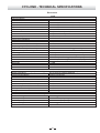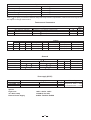
1
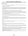
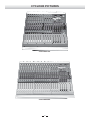
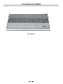
R
LTO
For music with passion
User's Manual
CYCLONE
large scale mixing console
R
LTO
www.altoproaudio.com
Version 1.0 APRIL. 2006
English
Fuse
SAFETY RELATED SYMBOLS
To prevent fire and damage to the product, use only
the recommended fuse type as indicated in this
manual. Do not short-circuit the fuse holder. Before
replacing the fuse, make sure that the product is
OFF and disconnected from the AC outlet.
CAUTION
RISK OF ELECTRIC SHOCK
DO NOT OPEN
This symbol, wherever used, alerts you to the presence of un-insulated and dangerous voltages within the product enclosure. These are voltages that
may be sufficient to constitute the risk of electric
shock or death.
Protective Ground
Before turning the product ON, make sure that it is
connected to Ground. This is to prevent the risk of
electric shock.
This symbol, wherever used, alerts you to important operating and maintenance instructions.
Please read.
Never cut internal or external Ground wires. Likewise,
never remove Ground wiring from the Protective
Ground Terminal.
Protective Ground Terminal
Operating Conditions
AC mains (Alternating Current)
Always install in accordance with the manufacturer's
instructions.
Hazardous Live Terminal
ON:
To avoid the risk of electric shock and damage, do
not subject this product to any liquid/rain or moisture.
Do not use this product when in close proximity to
water.
Denotes the product is turned on.
OFF: Denotes the product is turned off.
WARNING
Do not install this product near any direct heat source.
Describes precautions that should be observed to
prevent the possibility of death or injury to the user.
Do not block areas of ventilation. Failure to do so
could result in fire.
CAUTION
Keep product away from naked flames.
Describes precautions that should be observed to
prevent damage to the product.
IMPORTANT SAFETY INSTRUCTIONS
Read these instructions
Disposing of this product should not be
placed in municipal waste and should be
Separate collection.
Follow all instructions
Keep these instructions. Do not discard.
Heed all warnings.
WARNING
Only use attachments/accessories specified by the
manufacturer.
Power Supply
Ensure that the mains source voltage (AC outlet)
matches the voltage rating of the product. Failure
to do so could result in damage to the product and
possibly the user.
Power Cord and Plug
Do not tamper with the power cord or plug. These are
designed for your safety.
Unplug the product before electrical storms occur
and when unused for long periods of time to reduce
the risk of electric shock or fire.
Do not remove Ground connections!
External Connection
Protect the power cord and plug from any physical
stress to avoid risk of electric shock.
If the plug does not fit your AC outlet seek advice from
a qualified electrician.
Always use proper ready-made insulated mains
cabling (power cord). Failure to do so could result
in shock/death or fire. If in doubt, seek advice from
a registered electrician.
Do not place heavy objects on the power cord. This
could cause electric shock or fire.
Cleaning
When required, either blow off dust from the product
or use a dry cloth.
Do Not Remove Any Covers
Within the product are areas where high voltages
may present. To reduce the risk of electric shock do
not remove any covers unless the AC mains power
cord is removed.
Do not use any solvents such as Benzol or Alcohol.
For safety, keep product clean and free from dust.
Servicing
Covers should be removed by qualified service
personnel only.
No user serviceable parts inside.
Refer all servicing to qualified service personnel only.
Do not perform any servicing other than those instructions contained within the User's Manual.
1
PREFACE
Dear Customer:
Thank you for choosing the
For
LTO CYCLONE which is the result of our
LTO AUDIO TEAM's endeavours.
LTO AUDIO TEAM music and audio are much more than a job, they are a passion and an obsession!
We have, in fact, been designing professional audio products for a number of years in cooperation with many of the
world's major brands.
The LTO line represents unparalleled analogue and digital products made by musicians, for musicians. With our
design centres in Italy, the Netherlands, and the United Kingdom we provide you with world-class designs, while our
software development teams continue to develop an impressive range of audio specific algorithms.
By purchasing our LTO products you become the most important member of our LTO AUDIO TEAM. We would
like to share with you our passion for what we design and we invite you to make suggestions, which will aid us in developing future products for you. We guarantee you our commitment to quality, continual research and development,
and of course the best performance/price ratio.
The LTO CYCLONE is a large format versatile 4-bus sound reinforcement mixing console designed for all types
of live sound production as well as for recording purposes. Each channel is equipped with a variety of key features
including a warm, natural sounding four band sweep EQ (4 band fixed EQ for stereo channels), 6 Auxiliary sends,
Level Set preamp and fader LEDs etc.. Besides, the CYCLONE is equipped with fully featured oscillator and talkback
sections that will allow the sound engineer to work in a very fast and reliable way. Seeing is believing, let's meet LTO
CYCLONE.
We would like to thank all the people that worked with us to make a vision real! Our designers and LTO staff made
the LTO CYCLONE, the large format 6-bus sound reinforcement mixing console, a very reliable and high quality product
ready for all your venues. And thanks to their passion for music and professional audio it has been possible for us to
offer you, our most important team member, our continued support too.
Thank you very much
LTO AUDIO TEAM
2
TABLE OF CONTENTS
SAFETY INSTRUCTIONS ..........................................................................................................................1
PREFACE ...................................................................................................................................................2
TABLE OF CONTENTS .............................................................................................................................3
INTRODUCTION ........................................................................................................................................4
MAIN FEATURES ......................................................................................................................................5
INSTALLATION AND CONNECTIONS ......................................................................................................6
CYCLONE PICTURES ...............................................................................................................................8
FUNCTIONAL DESCRIPTION .................................................................................................................10
Cyclone Mono input channels ................................................................................................................10
Cyclone Stereo input channels ..............................................................................................................15
Cyclone Master Section .........................................................................................................................20
CYCLONE CONNECTIONS WIRING ......................................................................................................28
TECHNIQUE & TROUBLESHOOTING ...................................................................................................32
GLOSSARY ..............................................................................................................................................37
BLOCK DIAGRAMS ...............................................................................................................................38
TECHNICAL SPECIFICATIONS ..............................................................................................................39
WARRANTY .............................................................................................................................................41
3
INTRODUCTION
Our current top mixer line...fitted with a wide range of controls to satisfy the needs of the most demanding professional
with its real hi-fi specs and its user-friendly and ergonomic design despite the very high quantity of controls! These
models are ideal for large venue and large bands.
Thank you very much for expressing your confidence in LTO products by purchasing LTO's large format mixing
console Cyclone, an 4-bus sound reinforcement mixing console designed for all types of live sound production. We're
proud to introduce you our large format mixing console, designed and developed to meet the needs of the demanding
live sound engineers, providing the quality, all the features and the reliability you deserve, with its real hi-fi specs and
its user-friendly and ergonomic design despite the very high quantity of controls!
The Cyclone is an all purpose FOH mixing console that can be used as Monitor mixer as well, thanks to its 6 independent auxiliary sends. Each mono channel offers microphone and line input and insert points, lo-cut filter, four band
Sweep EQ. etc. The stereo channel offers stereo (left & right) line input with four band fixed EQ, as well as mono input
with discrete mic &line connections and Low-cut filter.
Following the needs of professional live sound engineers we included a lot of special features, like the Talkback section
the frequency Oscillator, one CLIP and one Level Set indicator to immediately understand at a glance the behaviour of
every channel mono signal.
The Cyclone is a large format professional mixing console. You will get a smooth, accurate more natural and open
sound from this tool, it is really ideal for gigs, recording and fixed PA installations.
Your Cyclone has been designed to be a very versatile and user-friendly mixing console, so it's very easy to operate
but we advise you to go through each section of this manual carefully. In this way you will get the best out of your
Cyclone in all application.
4
MAIN FEATURES
Pre-insert preamp Level Set LED
Extremely high headroom offering excellent dynamic range
Pre-fader, pre-eq channel insert
MIC input channels with golden plated XLRs and balanced LINE inputs
2-band fixed and 2-band sweep EQ on mono channels
4 Stereo input channels with left-right balanced TRS jacks, and mono MIC
4-band fixed EQ on stereo channels
Ultra-low noise discrete Mic Preamps with +48V Phantom Power
100mm high precision faders
Each input channel features Mute & SOLO switches, Overload & signal present LEDs and low cut filters
Fader CLIP LED
SUB 1-2-3-4 & MAIN L-R signal assignment switch
6 AUX all individually assignable pre/post with AFL mode.
Channel insert on each mono channel for connection of outboard equipment
Main Mix insert for flexible connection of outboard equipment
4 AUX return inputs can output from AUX1-6 and PLF output.
Fully assignable Oscillator and Talkback sections
XLR socket for lighting lamps
2-TRACK IN path
Highly accurate 8 segment output level meters
5
INSTALLATION AND CONNECTIONS
[ INSTALLATION ]
The following counsels must be observed to maintain safety and electromagnetic compatibility performance in order
to obtain the best possible performances by your Cyclone.
Earthing & Power Connections
Since all the signals are referenced to earthing system, it's very important that it's clean and noise free. The best way
to do an earthing system is to use a "star fed" instead of "daisy chain". A "star fed" earth connection means that independent wires runs for each outlet, in this way you'll provide a safety reference screen for each single equipment.
Never mix the mains audio earthing outlets with light earthing outlets, it could very easily generate interferences and
audio degradation.
Please try to avoid placing the console close/on any power distribution units or power amplifiers.
When using an external power supply, it should be located as far as possible from the console.
The power supply should be set for the voltage supply available in your area and plugged into the mains socket using
the cable provided with the ground/screen connector properly connected. The Cyclone should only be operated with
the power supply connected to ground via the ground in the mains connector. The use of alternative power supplies
may cause damage and void the warranty.
The power supply should never be operated with the mains earth disconnected
Please note that the power supply contains DANGEROUS VOLTAGES, much stronger than the mains voltage.
The power supply rails can produce extremely large currents which could burn out equipment and wiring if shorted.
Electric & Magnetic Fields
When the console is operated close to an electromagnetic field (generated by video monitors, high-power electric
cabling, etc.), you should detect an audio degradation induced by voltage picked up by leads and chassis. In this case
the signal to noise ratio may be degraded, under extreme conditions (3V/m, 90% modulation) degradation of up to
40dB may be experienced.
Wiring
To ensure the correct and reliable operation of your Cyclone mixing console, only high quality screened twisted pair
audio cable and metal bodied connectors should be used.
Position
Place the mixing console on a flat and even surface, avoiding extremely hot, cold, dust or humid places.
Your Cyclone should be situated so that its location or position does not interfere with its proper ventilation (e.g. on
a carpet, on felt, etc.).
When positioning the console for front of house usage it is worth placing the console in the "sweet spot" position
(where the sound system used can be properly heard from the mix position). Try to avoid placing the console behind
pillars or large objects , or mixing from a level above the speaker position (e.g. from a balcony).
WARNING: Always switch off the power supply before connecting or disconnecting the mixer power cable, removing
or installing modules, and servicing. In the event of an electric storm or large mains voltage fluctuations,
immediately switch off your Cyclone and disconnect the mains plug from its socket.
WARNING: Do not replace the fuse with any other type, or short-circuit the broken fuse, this could become
a safety hazard and will void the warranty.
WARNING: All servicing should ONLY be carried out by skilled personnel of an authorized maintenance centre.
6
[ CONNECTIONS ]
All connector shells should be of metal construction in order to provide a screen when connected to the console.
The Cyclone deserves to be operated with high quality twisted-pair audio cables to develop its full audio performances.
XLR plug & socket
Pin 1 - Screen/Ground
Pin 2 - Hot Signal
Pin 3 - Cold Signal
6,3mm. (1/4") Jack - BALANCED connections
TRS signal
Sleeve Screen/Ground
Ring Cold signal
Tip Hot signal
6,3mm. (1/4") Jack - unbalanced connections
TS signal
Sleeve Screen/Ground
Tip Signal
6,3mm. (1/4") TRS insert
Sleeve Screen/Ground
Ring Insert return
Tip Insert send
6,3mm. (1/4") TRS headphone
Sleeve Screen/Ground
Ring Right signal
Tip Left signal
Owner's manual conventions
Writing this owner's manual we used the following conventions:
1. The names of the keys switches and connectors used in this owner's manual match the labels on the unit
Examples: MIC IN
-> Microphone input
MID-H
-> Mid-High frequency boost/cut control
GR1-GR2 -> Group 1 & Group 2
2. The condition of the indicators on your mixer is surrounded by " ", e.g. "light" or "flash".
7
CYCLONE PICTURES
CYCLONE 160
CYCLONE 240
8
CYCLONE PICTURES
CYCLONE 320
9
FUNCTIONAL DESCRIPTION
[ Cyclone Mono Input Channels ]
The Cyclone is supplied with all the connections which pro users deserve to connect every kind of signal sources to
Cyclone inputs.
Insert
This unbalanced 1/4" jack connector has been designed to be used as insert
point, breaking the signal path immediately after the preamp section and
before the EQ section to allow the pro user to insert a dynamic compressor,
a parametric EQ, as well as other ancillary equipment. Please note that the
Mute switch of the channel does not affect this connector. The wiring is
Tip = Insert Send, Ring = Insert Return, Sleeve = Screen.
INSERT
MIC IN
LINE IN
Line in
This balanced input connector has been designed to accept line inputs up
to +22dBu. You can connect here keyboards outputs, mixer outputs, tape
outputs, etc. The wiring is Tip = Hot, Ring = Cold, Sleeve = Screen.
LINE IN
INSERT
MIC IN
MICROPHONE in
CH 2
This XLR socket has been designed to accept microphone signals up to
+22dBu, providing phantom power for condenser microphone when the
switch in the front panel is engaged. Pin1 = Screen/Ground, Pin2 = Hot
Signal, Pin3 = Cold Signal.
10
CH 1
[ Cyclone Mono Input Channels ]
We perfectly know the importance of the preamp section, a good preamp section will allow the sound engineer to work
with maximum dynamics, an exceptional signal-to-noise ratio... then to be able to use EQ, external dynamic controls
and other ancillary equipment to shape its own sound!
The Cyclone preamp section features all the useful controls to accurately manage the sound source in the most versatile way.
PHANTOM POWER switch & LED
The switch must be engaged when you're using a condenser microphone
or a direct box that can be powered by phantom power, instead of batteries.
The LED gives the user a visual control over channels with phantom
power on.
PHANTOM 48V
PHASE
PHASE switch & LED
GAIN LEVEL
This switch allows the user to invert by 180 the signal. This switch is very
useful in a lot of circumstances, in particular when several microphones are
very close (e.g. drum kit, brasses, chorus, etc.) and the sound engineers notices
interferences between microphones that can not be solved moving the
microphones. The LED gives an immediate control over channels with inverted
phase electronic circuits.
SET
0
-25
+60
+35
HIGH PASS
GAIN & LEVEL SET LED
The GAIN control gives you the chance to continuously adjust the preamplifier
gain for input signal. This control can be adjusted in 0/+60dB range for microphone
input and -25/+35dB for line input. The LEVEL SET LED will help the sound engineer to immediately detect the input level. In
this case the research of the fault will become much faster!
HIGH PASS switch & LED
This section allows the sound engineer to reduce the lower frequencies by engaging the switch This control is very useful
when you detect hum or rumble or you want to cut unwanted low frequency sounds picked-up by microphones. The LED
shows if the HIGH PASS section is active or not.
11
[ Cyclone Mono Input Channels ]
We provided a very versatile EQ circuit with two sweep filters to satisfy professional users demand. Thanks to the
wide overlap section of the 4 filters, this EQ allows to shape in a very efficient way the sound of all the sound sources
which the sound engineers has to manage.
HIGH gain
It's a shelving filter giving the user a continuous adjustment of boost
and cut from +15dB to -15dB @15KHz.
0dB
HIGH
15KHz
MID-H gain
-15
+15
0dB
MID-H
MID-H freq
It's the control to set the centre frequency of the MID-H control. It can
be adjusted in 800~8kHz range. It affects the frequency area from the
upper fundamental frequencies up to the higher harmonic frequencies,
allowing the skilled user to add or to subtract brightness to sound sources
to avoid masking frequencies effects.
-15
3.2
+15
EQ
It's a peak/dip filter giving the user a continuous adjustment of boost
and cut from +15dB to -15dB @800~8KHz.
MID-H
freq
KHz
.8
8
0dB
MID-L
MID-L gain
It's a peak/dip filter giving the user a continuous adjustment of boost
and cut from +15dB to -15dB @160~1.6KHz.
-15
+15
640
MID-L
freq
Hz
MID-L freq
1.6K
160
0dB
It's the control to set the centre frequency of the MID-L control. It can
be adjusted in 160~1.6kHz range. It affects the frequency area of most
of fundamental tone frequencies up to lower harmonic frequencies,
allowing the skilled user to add/subtract impact and/or presence to
sound sources giving them a particular sound character.
LOW
80Hz
-15
+15
LOW gain
It's a shelving filter giving the user a continuous adjustment of boost and cut from +15dB to -15dB @80Hz.
12
[ Cyclone Mono Input Channels ]
At LTO we thought that you deserve a very versatile auxiliary section. So we provided you six auxiliary sends.
These AUX sends can control the signals level which come from AUX output, but they have no effect to the main output.
AUX 1
AUX 2
-
The AUX 3 send level can be adjusted from -
0dB
up to +10dB.
-
AUX 3
+15
0dB
8
The AUX 2 send level can be adjusted from -
-15
8
up to +10dB.
0dB
-
0dB
AUX 4
+10
AUX2
+10
AUX3
+10
AUX4
up to +10dB.
-
8
The AUX 4 send level can be adjusted from -
AUX1
up to +10dB.
8
The AUX 1 send level can be adjusted from -
0dB
+10
AUX5
AUX 5
up to +10dB.
-
8
The AUX 5 send level can be adjusted from -
0dB
+10
AUX6
The AUX 6 send level can be adjusted from -
up to +10dB.
13
-
8
AUX 6
+10
[ Cyclone Mono Input Channels ]
The assign section is useful to manage the output assignment to several outputs, listen "in Solo" a channel and mute
or not a channel signal.
OUTPUT Assign to 1/2, 3/4, L/R
These switches allow the sound engineer to address the signal to selected audio
path. The odd/even numbered switches are used to send the signal to sub-groups
while L/R switch sends the signal directly to Main Mix output.
Please check the "technique & trouble-shooting" section of this owner's manual for
further details about the way to use those switches.
1
3
2
4
L
R
centre
Left
PAN
Right
PAN
This pot allows the sound engineer to place the channel signal in a stereo front from
hand left to hand right. Of course you can use it also to "move" the channel signal in
stereo front to create spatial effects.
CLIP
MUTE
-20
10
MUTE
You can use the MUTE switch to mute the channel signal when you don't need its
sound.
5
0
-20 & CLIP LEDs
These LEDs are very useful to control the behaviour of the channel signal path
after the EQ section and before the fader. In this both cases the presence of two
CLIP LEDs will help the sound engineer to immediately detect where is the problem.
5
10
20
Fader
This long coarse fader will give the sound engineer the ability to accurately manage the
channel output level from - up to +10dB.
This switch allows the sound engineer to control the channel signal. The PFL
(pre-fade listen) signal is pre-fader and mono When this large switch is engaged,
it's illuminated to give you an immediate visual control of which, and how many
channels are in PFL.
40
50
60
-
8
PFL switch
30
PFL
ON
OFF
CH 1
14
[ Cyclone Stereo Input Channels ]
Each Cyclone is supplied with four stereo input channels. These channels are ideal for stereo signals but we included
the same circuit of mono inputs, with discrete preamp level section and low-cut filter. So the sound engineer has the
choice to use a mono signal and a stereo signal outputs in the same channel in different times without being obliged
to change the GAIN control!
RIGHT
This balanced input connector has been designed to accept line
inputs up to +22dB. This connector should be only used for the
right output of an instrument. The wiring is Tip = Hot, Ring = Cold,
Sleeve = Screen.
RIGHT
LEFT IN (MONO)
MIC IN
This balanced input connector has been designed to accept line
inputs up to +22dB. This connector should be used for the left or
mono output of an instrument. This input follows the stereo path.
The wiring is Tip = Hot, Ring = Cold, Sleeve = Screen.
LEFT IN (MONO)
LEFT IN (MONO)
MICROPHONE in
This XLR socket has been designed to accept microphone signals
up to +22dB, providing phantom power for condenser microphone
when the switch in the front panel is engaged. Pin1 = Screen/
Ground, Pin2 = Hot Signal, Pin3 = Cold Signal.
15
RIGHT
MIC IN
ST2
ST1
[ Cyclone Stereo Input Channels ]
The Cyclone preamp section is fully featured with all the useful controls to manage the sound source. There are two
different preamp input path for mono or stereo signals, the latter features just GAIN while the mono preamp input is
regularly featured like any other mono input. In this way the sound engineer can use, for example, the stereo keyboard
outputs in the same channel of the entertainer voice, if both signals are not required at the same time and each source
will has its own level control.
PHANTOM POWER switch & LED
The switch must be engaged when you're using a condenser microphone or a direct box that can be powered by phantom
power, instead of batteries. The LED gives the user a visual control over channels with phantom power on.
PHASE switch & LED
This switch allows the user to invert by 180 the signal. This switch is very useful in a lot of circumstances, in particular
when several microphones are very close (e.g. drum kit, brass, choirs etc.) and the sound engineer notices interferences
between microphones that can't be solved by moving the microphones. The LED gives an immediate control over
channels with inverted phase electronic circuits.
MONO IN GAIN & LEVEL SET LED
The GAIN control gives you the chance to continuously adjust the preamplifier gain for input signal. This control can be
adjusted in 0/+60dB range for microphone input. The LEVEL SET LED will help the sound engineer to immediately detect
the input level. In this case the research of the fault will become much faster!
HIGH PASS switch & LED
This section allows the sound engineer to reduce the lower frequencies of MONO INPUT
by engaging the switch This control is very useful when you detect hum or rumble or
you want to cut unwanted low frequency sounds picked-up by microphones. The LED
shows if the HIGH PASS section is active or not.
PHANTOM 48V
PHASE
MONO IN
GAIN LEVEL
SET
STEREO IN GAIN
The GAIN control gives you the chance to continuously adjust the amplifier gain
for LEFT (MONO) & RIGHT inputs. This control can be adjusted in -20/+20dB
range input.
0
+60
HIGH PASS
INPUT SELECT switch
STEREO IN
GAIN
Pressing this switch you'll select the mono input source for this channel, while
releasing this switch you'll use the stereo signal.
- 20
INPUT SELECT LED
+20
INPUT SELECT
This LED is lit when you use a mono signal, the INPUT SELECT switch is pressed.
STEREO
MONO
16
[ Cyclone Stereo Input Channels ]
Stereo sources are generally keyboards outputs, pre-mixers, etc., so the signal deserves few EQ adjustments. For
this reason we choose for the Cyclone stereo channels a four band fixed EQ.
HIGH gain
0dB
HIGH
12KHz
It's a shelving filter giving the user a continuous adjustment of boost and
cut from +15dB to -15dB @ 12kHz.
-15
+15
0dB
MID-H
MID-H
It's a peak/dip filter giving the user a continuous adjustment of boost and
cut from +15dB to -15dB @ 3kHz.
-15
+15
0dB
EQ
3KHz
MID-L
400Hz
MID-L
-15
+15
0dB
It's a peak/dip filter giving the user a continuous adjustment of boost and
cut from +15dB to -15dB @ 400Hz.
80Hz
-15
LOW
It's a shelving filter giving the user a continuous adjustment of boost and
cut from +15dB to -15dB @ 80Hz.
17
LOW
+15
[ Cyclone Stereo Input Channels ]
At LTO we thought that you deserve a very versatile auxiliary section. So we provided you the same six discrete
auxiliary sends of mono channels, with independent level controls.
AUX 1
The AUX 1 send level can be adjusted from -
up to +10dB.
0dB
AUX1
up to +10dB.
AUX 3
-
0dB
-
8
The AUX 2 send level can be adjusted from -
8
AUX 2
0dB
up to +10dB.
-
8
The AUX 3 send level can be adjusted from -
0dB
AUX 4
AUX2
+10
AUX3
+10
AUX4
up to +10dB.
-
8
The AUX 4 send level can be adjusted from -
+10
0dB
+10
AUX5
AUX 5
up to +10dB.
-
+10
8
The AUX 5 send level can be adjusted from -
0dB
AUX6
The AUX 6 send level can be adjusted from -
up to +10dB.
18
-
8
AUX 6
+10
[ Cyclone Stereo Input Channels ]
The assign section is useful to manage the output assignment to several outputs, and also to PFL or MUTE a channel
signal.
OUTPUT Assign to 1/2, 3/4, L/R
These switches allow the sound engineer to address the signal to the selected
audio path. The odd/even numbered switches are used to send the signal to
sub-groups while L/R switch sends the signal directly to Main Mix output. Please
check the "technique & troubleshooting" section of this owner's manual for further
details about the way to use those switches.
1
3
2
4
L
R
centre
BAL
BAL
Left
This pot allows the sound engineer to manage the balance of a stereo source
or to place the channel mono signal in a stereo front from hand left to hand
right. Of course you can also use it to "move" the channel signal in stereo
front to create spatial effects.
Right
CLIP
MUTE
-20
MUTE
You can use the MUTE switch to mute the channel signal when you don't
need its sound. When this large switch is engaged, it's lit.
10
5
-20 & CLIP LEDs
These LEDs are very useful to control the behaviour of the channel signal
path after the EQ section and before the fader. In this both cases the presence
of two CLIP LEDs will help the sound engineer to immediately detect where
is the problem.
0
5
10
Fader
This long coarse fader will give the sound engineer the ability to accurately
manage the channel output level from - up to +10dB.
20
30
PFL switch
40
50
60
-
8
This switch allows the sound engineer to control the channel signal. The PFL
(pre-fade listen) signal is pre-fader and stereo for stereo inputs and mono for
mono inputs. When this large switch is engaged, it's illuminated to give you
an immediate visual control of which, and how many channels are in PFL.
PFL
ON
OFF
ST1
19
[ Cyclone Master Section ]
The master section is the richest section of the mixer with plenty of inputs, outputs and control switches.
Here's a detailed description of each connector.
RTN1 LEFT (MONO) & RTN1 RIGHT
These balanced connectors are for stereo auxiliary return 1.
Connecting a plug just to LEFT input it will act as a mono
effect return.
RTN2 LEFT (MONO) & RTN2 RIGHT
These balanced connectors are for stereo auxiliary return 2.
Connecting a plug just to LEFT input it will act as a mono
effect return.
RTN4 L
(MONO)
RTN3 L
(MONO)
RTN2 L
(MONO)
RTN1 L
(MONO)
RTN4 R
RTN3 R
RTN2 R
RTN1 R
RTN3 LEFT (MONO) & RTN3 RIGHT
These balanced connectors are for stereo auxiliary return 3.
Connecting a plug just to LEFT input it will act as a mono
effect return.
AUX RETURN
RTN4 LEFT (MONO) & RTN4 RIGHT
These balanced connectors are for stereo auxiliary return 4.
Connecting a plug just to LEFT input it will act as a mono
effect return.
GR 1 OUT
This unbalanced1/4"TRS connector is for group 1 output.
GR 2 OUT
GR2 OUT
GR1 OUT
GR4 OUT
GR3 OUT
This unbalanced1/4"TRS connector is for group 2 output.
GR 3 OUT
This unbalanced1/4"TRS connector is for group 3 output.
GR 4 OUT
GROUP OUT
This unbalanced1/4"TRS connector is for group 4 output.
TAPE IN LEFT & RIGHT
These RCA jacks have been designed to accept tape returns
inputs.
TAPE IN TAPE OUT
TAPE OUT LEFT & RIGHT
LEFT
These RCA jacks have been designed to output the main
mix signal into a tape recorder or audio board stereo input.
RIGHT
2-TRACK
20
[ Cyclone Master Section ]
AUX 1 OUT
This unbalanced1/4" TRS connector is for auxiliary 1 send.
AUX 2 OUT
This unbalanced1/4" TRS connector is for auxiliary 2 send.
AUX 3 OUT
This unbalanced1/4" TRS connector is for auxiliary 3 send.
AUX3 OUT
AUX2 OUT
AUX1 OUT
AUX5 OUT
AUX4 OUT
AUX 4 OUT
This unbalanced1/4" TRS connector is for auxiliary 4 send.
AUX6 OUT
AUX 5 OUT
AUX SENDS
This unbalanced1/4" TRS connector is for auxiliary 5 send.
AUX 6 OUT
This unbalanced1/4" TRS connector is for auxiliary 6 send.
EXTERNAL POWER SUPPLY CONNECTOR
CYCLONE has two external power supply connectors, one is
MAIN POWER, the other is BACKUP POWER. These two
connectors are used to connect the unit to the mains with the
enclosed power cord.
ATTENTION:
1. Use only original power supply!
2. To get best performance and avoid any interference, it is
better to setup the power supply 1m far away from the main
mixer unit.
21
EXTERNAL POWER SUPPLY CONNECTOR
MAIN POWER
BACKUP POWER
ATTENTION: USE ONLY ORIGINAL POWER SUPPLY
[ Cyclone Master Section ]
LIGHT
This 4-pin XLR connector must be used
to connect 12V DC lamps(Max 8W).
This input is for a talkback microphone,
Which will be managed by SOURCES
section.
1
4
TALKBACK INPUT
3
TALK BACK
INPUT
2
LIGHT
12VDC 8W max
HEADPHONES
OUT
HEADPHONES OUT
This socket will send out the control
Room signal to the headphone.
CTRL LEFT & RIGHT OUT
LEFT
These 1/4" sockets are used to send the control room signal to the studio monitor
speakers or a second set of PA.
RIGHT
CTRL
OUT
LEFT OUT & RIGHT OUT and INSERTs
These balanced XLR connectors output the LEFT/RIGHT
MASTER signals, and include a pre-fader insert unbalanced
connector for each output.
LEFT
RIGHT
LEFT
RIGHT
MAIN OUT
22
MAIN
INSERT
[ Cyclone Master Section ]
TAPE IN LEVEL
This pot will give the sound engineer the ability to manage the tape return
signal level from - up to +10dB.
OUTPUT Assign to 1/2, 3/4, L/R
TAPE IN
0dB
LEVEL
GR
1
2
-
GR
+10
8
These switches allow the sound engineer to address the signal to the audio
path which he wants to. The odd/even numbered switches are used to send
the signal to sub-groups (then you can send their signal to L/R outs) while
L/R switch sends the signal directly to Main Mix output. Those switches can
be set in several ways.
3
4
L
R
PFL
PFL switch
This switch allows the sound engineer to control the TAPE IN signal. The PFL
(pre-fade listen) signal is pre-fader and stereo. This large switch is illuminated
to give you an immediate visual check of current status.
ST RTN level
AUX RETURN
This pot will give the sound engineer the ability to carefully manage the aux
return signal level from - up to +10dB.
ST RTN 1
ST RTN 2
0dB
0dB
LEVEL
LEVEL
-
8
0dB
0dB
8
-
+10
0dB
AUX1
-
+10
8
-
These pots will allow the sound engineer to send the FX return signal to Auxiliaries.
In this way you can send, e.g., to the lead singer monitor the reverb that affects
the entire mix.
8
AUX 1-6
0dB
AUX2
+10
AUX1
+10
AUX2
-
-
This switch allows the sound engineer to control the aux return signal. The PFL
(pre-fade listen) signal is pre-fader and stereo. This large switch is illuminated
to give you an immediate visual Check of current status.
-
+10
8
0dB
-
+10
8
8
0dB
-
MUTE
+10
AUX4
AUX5
+10
BAL
Right
MUTE
ON
OFF
PFL
23
AUX6
+10
centre
Left
Right
AUX3
+10
AUX6
BAL
+10
0dB
AUX5
+10
centre
Left
0dB
AUX4
8
PFL switch
-
-
+10
0dB
This switch is useful to mute that aux return signal when you don't need its
sound. This feature is important to reduce noise floor of effects units. This
switch will be lit when it is depressed (engaged).
0dB
AUX3
8
0dB
-
+10
8
-
8
0dB
8
MUTE
-
8
This pot controls the balance between left and right signal coming from the effects
outputs. Its behaviour is similar to pan-pot, but the result is different since it doesn't
place the signal in stereo front, but it just manages the balance between the
outputs of the stereo effects unit. Of course if you connect a plug only to LEFT
(MONO) input it acts as a regular pan-pot.
8
BAL
ON
OFF
PFL
[ Cyclone Master Section ]
The aux send section is useful to control the overall level of the send to a monitor speaker or to an effects unit.
Generally pre-fader is used for monitor purposes, allowing the sound engineer to set a level that's independent by
channel fader setting. In this way the control will be much more accurate and the sound engineer doesn't risk unwanted
feedback when, for example, he raises the level of the lead singer. Post-fader sends are better suited for FX sends
control. By doing so, for example, the sound engineer will raise the fader level of the lead singer the effect send as
well, maintaining the same sound balance between "dry" & "wet" signals. Please note that the channel Mute switch
affects these controls.
PRE switch
Press this pre-fader switch, the signal is sent out before all
channel faders and will not be affected by each channel fader.
AUX1
0dB
PRE
AFL switch
-
AUX2
PRE
0dB
+10
PRE
8
AFL
-
AUX4
0dB
+10
PRE
up to +10dB.
8
AFL
-
AUX 3
The AUX 3 send level can be adjusted from -
+10
up to +10dB.
AUX 2
The AUX 2 send level can be adjusted from -
8
AUX3
AUX 1
0dB
AFL
-
The AUX 1 send level can be adjusted from -
8
AFL
This switch allows the sound engineer to control the AUX send
signal. AFL is the acronym of after-fade listen, the signal is
post-fader. The LED next to this large switch is illuminated
to give you an immediate visual check of current status.
AUX5
0dB
+10
PRE
up to +10dB.
AUX 4
The AUX 4 send level can be adjusted from -
-
8
AFL
AUX6
0dB
+10
PRE
up to +10dB.
AUX 5
The AUX 5 send level can be adjusted from -
-
up to +10dB.
AUX 6
The AUX 6 send level can be adjusted from -
up to +10dB.
24
8
AFL
+10
[ Cyclone Master Section ]
The group section contains all the controls for level and soloing the group signal. The most important feature is the
To L/R switch that allows the sound engineer to use in a different way the group signal. Generally this switch is
released when the sound engineer wants to record some grouped signals, while the switch is pressed when the sound
engineer wants to use the groups signal as a part of the signal to be addressed to stereo mix. The main difference
between the above mentioned ways of working concerns the way to group signals.
GR1
To L/R switch
L
This switch addresses the group signal to L/R path.
R
Fader
This long throw fader will give the sound engineer the ability to carefully
manage the group level from - up to +10dB.
10
5
PFL
This switch allows the sound engineer to control the group signal. PFL is
the acronym of pre-fade listen, the signal is pre-fader. This large switch
is illuminated to give you an immediate visual control of which, and how
many channels are in PFL.
0
5
10
20
30
8
40
50
60
-
PFL
ON
OFF
GR 1
25
[ Cyclone Master Section ]
Master section controls are the most important in every mixer, these controls affect the overall level, the headphone
listening, control room, Talkback and so on.
LEVEL
This is the main level control for the talkback and oscillator section.
TALKBACK / OSC
0dB
ON
LEVEL
AUX
GR
-
1
2
+10
8
This switch activates and sends the talk-back/osc signal to its selected
outputs.
SELECT
OSC
TB
1
2
AUX
GR
3
4
TALKBACK SECTION SEL TALKBACK switch
This switch will select the Talkback source (generally it's a microphone)
to communicate with musicians and other people on stage.
3
4
AUX
L
R
ON
5
6
TALKBACK SECTION SEL OSCILLATOR switch
This switch will select the Oscillator as source signal for this mixer
section. Generally the oscillator is used for level settings of recorders.
OUTPUT Assign to 1/2 3/4 L/R
These switches allow the sound engineer to assign the talkback / osc
signal to the audio path he wants to.
The odd/even numbered switches are used to send the signal to sub
-groups (then you can send their signal to L/R outs) while L/R switch
sends the signal directly to Main Mix
Output Assign to AUX 1/2, AUX 3/4, AUX 5/6
Those switches will allow the sound engineer to address the sources
signal to Auxiliaries. In this way you can send, e.g., the Talkback signal to
all stage monitors to communicate directly with performers while audience
will hear nothing.
POWER SUPPLY MONITOR
These three LEDs will light up when the unit is powered on.
POWER SUPPLY MONITOR
+18
LED level ladder
This 8-LED very accurate level indicator is another useful tool of Cyclone
which provides sound engineers perfectly control mixer behaviour.
LEFT
-18
+48
RIGHT
18
18
12
12
PFL/AFL LED
6
6
This LED shows the status of the level indicator when any PFL /AFL
switch is pressed.
0
0
-6
-6
-12
-12
-18
-18
-24
-24
AFL / PFL
26
[ Cyclone Master Section ]
CONTROL ROOM level
0dB
LEVEL
This stereo pot will give the sound engineer the ability to carefully
manage the CONTROL ROOM level from - up to +10dB.
+10
8
-
CONTROL ROOM
HEADPHONE MONITORS level
0dB
This stereo pot will give the sound engineer the ability to carefully
manage the HEADPHONE MONITORS level from - up to +10dB.
-
8
LEVEL
+10
HEADPHONES
FADER
This long coarse stereo fader will give the sound engineer
the ability to carefully manage the master output level from up to+10dB.
10
5
0
5
10
20
30
8
40
50
60
-
MAIN L-R
27
CYCLONE CONNECTOR WIRING
The Cyclone uses standard pro audio connectors and wiring configurations
1/4" jack
XLR
Pin1 = Screen/Ground
Pin2 = Hot Signal
Pin3 = Cold Signal
MIC IN
1/4" jack TRS
Tip = Hot
Ring = Cold
Sleeve = Screen
LINE IN
1/4" jack TRS
Tip = Insert Send
Ring = Insert Return
Sleeve = Screen
INSERT
XLR
Pin1 = Screen/Ground
Pin2 = Hot Signal,
Pin3 = Cold Signal
AUX OUT
1/4" jack TRS
Tip = Hot
Ring = Cold
Sleeve = Screen
RTN IN
XLR
Pin1 = Screen/Ground
Pin2 = Hot Signal
Pin3 = Cold Signal
MIX out
XLR
Pin1 = Screen/Ground
Pin2 = Hot Signal
Pin3 = Cold Signal
GR OUT
Tip = Hot
Ring = Cold
Sleeve = Screen
TAPE IN
1/4" jack TRS
Tip = Hot
Ring = Cold
Sleeve = Screen
TAPE OUT
1/4" jack TRS
Tip = Hot
Ring = Cold
Sleeve = Screen
MONITOR
1/4" jack TRS
XLR
Pin1 = Screen/Ground
Pin2 = Hot Signal,
Pin3 = Cold Signal
TALKBACK
1/4" jack TRS
Tip = Send
Ring = Return
Sleeve = Screen
INSERT
1/4" jack TRS
Tip = Left
Ring = Right
Sleeve = Screen
HEADHPONE
XLR 4-pin
Pin 1: Chassis
Pin 2: n.c.
Pin 3: Ground
Pin 4: VCC
LAMP
+
-
Tip
Ring
Sleeve
TRS Type Balanced
+
Tip
Ring
Sleeve
TRS Type Unbalanced
+
Tip
Sleeve
TS Type Unbalanced
XLR connector
Pin2 (+)
Pin3 (-)
Pin1 ( )
XLR Type Balanced
Pin2 (+)
Pin3 (-)
(Linked to Pin1 manually,
)
Pin1 ( )
XLR Type Unbalanced
28
1/4" TRS insert
Lamp Connector
Send
Return
1
4
3
Ring
Tip
Pin 1: Chassis
Pin 2: n.c.
Pin 3: Ground
Pin 4: VCC
2
12VDC 8W max
Sleeve
[ Connectors needed: ]
160
240
320
MIC IN (total)
12
20
28
XLR socket (female)
LINE IN (mono CH)
8
16
24
1/4" (6.3mm) TRS jack plug (male)
LINE IN (stereo CH)
8
8
8
1/4" (6.3mm) TRS jack plug (male)
INSERT (mono CH)
8
16
24
1/4" (6.3mm) TRS jack plug (male)
AUX OUT
6
6
6
1/4" (6.3mm) TRS jack plug (male)
RTN IN
8
8
8
1/4" (6.3mm) TRS jack plug (male)
MIX out
2
2
2
XLR plug (male)
GR OUT
4
4
4
1/4" (6.3mm) TRS jack plug (male)
TAPE IN
2
2
2
1/4" (6.3mm) TRS jack plug (male)
TAPE OUT
2
2
2
1/4" (6.3mm) TRS jack plug (male)
TALKBACK
1
1
1
XLR plug (male)
INSERT
2
2
2
1/4" (6.3mm) TRS jack plug (male)
HEADHPONE
1
1
1
1/4" (6.3mm) TRS jack plug (male)
LAMP
1
1
1
XLR 4-pin
Kind of connectors needed
Inputs
outputs
29
For the right wiring please check also the following table
Sleeve
Ring=Right Signal
Tip
Ring
Strain Clamp
Tip=Left Signal
Sleeve=Ground/Screen
Use for Headphone
1/4" Stereo (TRS) Jack Plug
Sleeve
Tip
Tip=Signal
Strain Clamp
Sleeve=Ground/Screen
Use for Mono Line In, Mono 1/4"Jack Plugs
1/4" Mono (TS) Jack Plug
Sleeve
Ring=Return Signal
Tip
Ring
Strain Clamp
Tip=Send Signal
Sleeve=Ground/Screen
Use for Insert Points
1/4" Stereo (TRS) Jack Plug
2=Hot(+)
2
1
3
2=Hot(+)
1=Ground/Screen
3=Cold(-)
2
1
3
1=Ground/Screen
3=Cold(-)
Use for Balanced Mic Inputs
(For unbalanced use, connect pin 1 to 3)
Use for Main output
(For unbalanced use, leave pin 3 unconnected)
3-pin XLR Male Plug
3-pin XLR Line Socket
(seen from soldering side)
(seen from soldering side)
30
Ring=Return Signal (Connected together)
To Channel Insert
Sleeve=Ground/Screen
Tip=Signal
To Tape or FX Input
Sleeve=Ground/Screen
'Tapped' Connection Direct Output Lead
(Enables the Insert to be used as a Direct Output
while maintaining the channel signal flow)
To Processor Input
Sleeve=Ground/Screen
Tip=Send Signal
Tip
To Channel Insert
Sleeve
Ring=Return Signal
Ring
To Processor Output
-Stereo lead for insert Connection
(To be used when the external processor does not employ
a single jack connection for the In/Out Connections)
31
CYCLONE TECHNIQUE & TROUBLESHOOTING
This section of the owner's manual gives you some basic information about the technique how to get the best performances from your Cyclone. Of course there are several tricks and tips. The last part of this chapter is about troubleshooting.
GAIN settings
You should use the channel input gain to obtain the best operating level for the console. If the gain level is too low
the best signal to noise ratio won't be achieved. If the gain level is high you may risk to overload the channel causing
distortion. Clearly, the GAIN should be positioned between these two points, to gain an optimal signal to noise ratio
without overloading the channel. The ideal level for input channels is when the CLIP preamp LED just flashes on
musical peaks.
TIP
The presence in stereo channels of discrete input GAIN for mono input and stereo input allows the sound engineer
to use two different signals on the same input, for example the entertainer MIC and a stereo keyboard. So when
he has to use the MIC level he can choose MIC GAIN, but he can promptly change to stereo input line with right
GAIN setting, just pressing the INPUT SELECT key.
Headroom
Headroom is the amount of spare 'swing' available to the system. If 6dB headroom was desired at all times, a
maximum level of+15dBis required to retain the headroom. The consoles Busses (Sub-groups, Aux sends and
Left/Right Master) are the points where all channel signals are summed together. In normal operation, it's unlikely
that all channels will receive the peak signal at the same time, so typically when 48 channels are summed together
a gain of around 6 to 9dB will be seen. It is important to leave some headroom in the summing amplifiers so that
they do not overload, should the sum exceed the maximum level.
TIP
To prevent overload, during sound check the GAIN should be set to a point that even the highest output from the
microphone will turn on the CLIP preamp LED just during peak signals. In this way you should prevent any unpleasant surprise during the show!
INSERT
As explained before the insert point is a break in signal path that can be used for dynamic processing and/or fx
processing of a single input channel, sub-group, Aux send or Main Mix channel. Now we'll deeply investigate how
to obtain the best results from this section.
Generally during a show the sound engineer has to work with high dynamic signals (i.e. a vocalist performance)
so it's better to reduce the dynamic range of the signal. In this way there won't be louder peaks (avoiding channel
input overloading) or too low musical nuances (avoiding the channel noise floor to overcome these signals).
Limiters and Compressors are widely used for this application. The means by which they achieve this won't be
discussed here but these devices are used to automatically reduce the level of loud signals and also raise the gain
to 'make up' the level as desired. The channel gain can now be set with adequate headroom to accommodate both
loud and quiet signals and the compressor can reduce the dynamic range and 'make up' any reduction in level.
By inserting such a device into the channel's insert point you have the ability to remove the guess work from setting
your system gain.
32
However (and this is a big however), there are still sources of potential problems. The Cyclone is able to operate
at levels up to +21dBu on both the insert send and return. If the maximum input level of the compressor is less
than +21dBu then it is possible to overload the input of the compressor. The only way to solve this situation is to
drop the channel input gain so that the input level of the compressor will not overload. However, bear in mind that
the level returned from the compressor would also be lower than +21dBu and excessive use of the compressor
'makeup' gain would overload the output of the compressor!
Very often other dynamic processors are used like expanders or noise-gates, to reduce the inherent noise of some
sound sources, e.g. electric guitars, but in this case the signal overall level will not change. And the level could
slightly change with processors like Aural Exciters, Enhancer and De-Essers, but it those cases too the difference
is not dramatic!
Sometimes it happens that a special effect is used just for one channel, generally it's the lead singer voice, so the
sound engineer uses a "Channel strip" or some effects unit that have been programmed for the lead singer voice.
In both cases the sound engineer has to be very careful setting of these ancillary equipments since the first one
could drive the channel to overload, while the second one could reduce the level of the signal returning to the insert
point.
Equalization
Channel equalization should be used with care. Boosting or cutting equalizer bands can make monitoring your
actual input level very difficult.
Excessive boosting of EQ (+15dB is available on each band) will have the same effect as applying more gain to
the input, taking up valuable headroom. Consider backing off the channel GAIN when using large amounts of boost
(if you have to use large amounts of boost) to retain a sensible level at the output. In this case the preamp CLIP
LED will be turned off while the fader CLIP LED will be turned on!
Excessive EQ cut can have a similarly undesirable effect. If a large amount of signal is cut in the equaliser section,
GAIN may be used to 'make up' the level lost in the equaliser. However, the input pre-amplifier still has the same
amount of available headroom. If gain, added to 'make up' the loss in the equaliser, exceeds the maximum level
into the microphone pre-amp then the channel won't appear to be overloaded but the microphone pre-amp will.
Turning off the equaliser will reveal the true story, showing if the microphone pre-amp is overloaded. It is worth
considering whether such a large amounts of EQ boost or cut is really required.
TIP
To help sound engineers to detect a wrong EQ operation, we provided our Alto Cyclone with two level indicator
sections. In the preamp GAIN section there's a CLIP LEDs, and we provided a fader indicator section with two
LEDs: -20 and CLIP. In this way the sound engineer will immediately detect if the problem incurs in pre-amp section
or in signal path, generated by a wrong setting of EQ, insert ancillary equipment or fader.
33
EQ DIAGRAM
In recording studios as well as on stage, the versatile Cyclone EQ section is a valuable sound tool. Its controls will
allow the sound engineer to modify the frequency contour of sound to shape the character of instruments to obtain
the sound he wants to. The following frequency table gives you some basic information about the fundamental
frequencies of some musical instruments and of the human voice. Please use this table as a starting point for a
deeper understanding of the acoustic environment.
Typical Frequency of Human Voice and some Musical Acoustic Instruments
Mid C
CDEFGABCDEFGABCDEFGABCDEFGABCDEFGABCDEFGABCDEFGABCDEFGABCDEFGABC
25
31
40
50
62
80 100 125 160 200 250 320 400 500 640 800 1K 1.3K 1.6K 2K 2.5K 3.1K 4K
5K 6.2K 8K 10K 13K 16K 20K
Human hearing
range
VOCAL
Soprano
Contralto
Baritone
Bass
WOODWIND
Piccolo
Flute
Oboe
Clarinet in B flat or A
Clarinet in E flat
Bass Clarinet
Basset Hom
Cor Anglais
Bassoon
Double Bassoon
BRASS
Soprano Saxophone
Alto Saxophone
Tenor Saxophone
Baritone Saxophone
Bass Saxophone
Trumpet in C
Trumpet in F
Alto Trombone
Tenor Trombone
Bass Trombone
Tuba
Valve Hom
STRINGS
Violin
Viola
Cello
Double Bass
Guitar
KEYBOARDS
Pianoforte
Organ
PERCUSSION
Celesta
Timpani
Xylophone
25
31
40
50
62
80 100 125 160 200 250 320 400 500 640 800 1K 1.3K1.6K 2K 2.5K 3.1K 4K
34
5K 6.2K 8K 10K 13K 16K 20K
FREQUENCY
Assign keys
These switches allow the sound engineer to address the signal to the selected audio path. The odd/even numbered
switches are used to send the signal to sub-groups (then you can send their signal to L/R outs) while L/R switch
sends the signal directly to Main Mix output. These switches can be used in several ways to better suite your application:
Application
Live 1
Signals are grouped in a way that the sound engineer can easily control the band sections.
A typical setting is: drums, percussion and rhythmic instruments in stereo by subs 1-2, keyboards & guitars in stereo by subs 3-4, wind and brass in stereo by subs 5-6, lead singer,
choirs and voices in stereo, or in mono, by subs 7-8. Some sound engineers prefer to assign
the lead voice and lead guitar to mono groups (e.g. 7 and 8), while other engineers prefer to
directly assign those signals to LEFT/RIGHT MASTER. In this case the sub-group fader is
used to set the sub-group level, and "to LR" switch is engaged, of course no input channel
already assigned to sub-groups has to be assigned to LEFT/RIGHT MASTER.
Live 2
Signals are grouped in a way that the sound engineer uses for particular stage monitor purposes. For example sub-groups 1 & 2 are used for "side fills" for the lead singer, while subgroups 3 & 4 are used as "drum fills" for the drummer, etc. In this case the sub-group fader
is used to set the listening level, and "to LR" switch is not engaged and each input channel
has to be assigned both to sub-groups both to LEFT/RIGHT MASTER.
Signals are grouped to reach the desired channel of the multi-track recorder. Generally the
sound engineers groups together in stereo some parts of the drum kit (toms & over-head)
while other parts like bass drum, snare drum and hi-hat are recorded by the MAIN INSERT
of their own input channels. Another stereo group could be the keyboards. Generally lead
Multi-track recording
voice and lead guitar are picked-up directly by their channel MAIN INSERT. In this case the
sub-group fader is used to set the recording level and generally the "to LR" switch is not
engaged and each input channel has to be assigned both to sub-groups both to LEFT/
RIGHT MASTER.
Live = Multi-track
recording
In this case each sound engineer has his own way of working. The signal of sub-groups is
carefully set to record at the right level while the "to LR" switch is engaged to send all the
signals to LEFT/RIGHT MASTER. In this case no input channel already assigned to subgroups has to be assigned to LEFT/RIGHT MASTER.
35
Final links
The final links in audio systems are graphical equalisers, loudspeaker processors and finally amplifiers and speakers.
Graphical equalisers have the same problems as the Cyclone's EQ. If excessive boost is applied to the signal, the
graphic equaliser's output (and subsequent electronics too!) may be overloaded. If, Cyclone output is higher than
the maximum input level of the graphic, the input of the graphic equalizer may be overloaded.
Loudspeaker processors have similar problems. If the input level to the processor is too high, the input may be
overloaded and introduce distortion into the outputs (and to the speakers). In addition to this, any boost on the
processors outputs (e.g. 3dB more bass) will cause that output to overload earlier (in this case 3dB before the other
outputs). Finally, amplifiers can introduce the most interesting results. An amplifier has a sensitivity. That is, an
input signal level that causes the amplifier to produce it's maximum
output level. For most of the amplifiers it's 0dBu (0.775 volts RMS), others use 0dBV (1 volt RMS) others use different levels. Beyond this sensitivity, the amplifiers output will not be able to produce any more power and 'CLIP'
(usually indicated by some serious looking red lights). Sending +22dBu level from the Cyclone will clip the output
of most amplifiers causing damage to your loudspeaker system.
There are a number of solutions to this problem:
Reduce the amplifiers input attenuators to a level where the amplifier and console clip at the same point.
e.g. The input sensitivity is 0dBu, setting the input attenuator on the amplifier to +22dBu would mean that the
console would clip at the same time as the amplifier. So operating the console sensibly the amplifier should
never be clipped. The console LED Meters will also accurately show the available headroom left in the entire
system.
+22dBu may not be a sensible level to set as many operators choose not to run the output of the console so
high. That is personal choice.
Run the output of the console at a level below 0dBu
This solution means that you won't get full benefit of the console, and may suffer a reduced signal to noise ratio
especially when running over long signal cables. But the amplifiers should be saved from clipping.
As with many things in the audio world, use your ears. If something sounds distorted check:
Input Gain too high?
(lower input gain and check)
EQ Too Much Boost?
(disable EQ and check)
EQ Too Much Cut coupled with a High Input Gain?
(disable EQ and check)
Too High a level into Inserted Processor?
(disable insert and check)
Clipping Loudspeaker controller or Amplifiers?
(Check both CLIP LEDs)
36
GLOSSARY
In this owner's manuals we used terms of pro audio slang, here's the explanation of some of those words
SWEET SPOT
rd
It's the best place to listen to your mix, with all the details of stereo front, it's the 3 corner of a triangle, where the two
other corners are the speakers.
MAKE UP
It's totally different from your girlfriend beauty content...it's just the way compressors and limiters work in order not to
loose level.
DRY
It's just the original sound of every instrument and/or voice which are not affected by Fxs.
WET
It's the processed signal by an effect unit (reverb, delay etc.)
37
CYCLONE BLOCK DIAGRAM
38
CYCLONE - TECHNICAL SPECIFICATIONS
Electronics
Input Impedance
Input Gain Mic
Input Gain Line - Mono Channel
Input Gain Line - Stereo Channel
Maximum Input Level
Insert send impedance
Insert send level / Max.
Insert return impedance
Insert return level / Max.
CMR at 1kHz Line (20Hz - 20kHz)
Frequency response
Signal/Noise Ratio (20Hz - 20kHz)
System Noise (20Hz - 20kHz)
Summing Noise
Line to Mix Noise
Distortion at 1kHz
Crosstalk at 1kHz channel to channel
Mix to Mix
Channel to Mix
Fader Attenuation
Input
Mic 2kohm Balanced
Line 10kohm Balanced
Continuously variable from 0dB to +60dB
Continuously variable from -25dB to +35dB
Continuously variable from -20dB to +20dB
Mic +22dBu
Line (Mono Channel) +22dBu
Line (Stereo Channel) +22dBu
100ohm Unbalanced
-10dBu / +22dBu
10kohm Unbalanced
-10dBu / +22dBu
> 80dB
Mic to Mix 20Hz - 20kHz +0/-1dB
Mic EIN ref. 150ohms - 101dBu (gain +60dB)
-85dBu (16 channels routed with faders down)
-83dBu (16 channels routed at 0dB, pan centre)
Mic to Insert (+30dB unity gain, +20dBu output) <0.01%
Mic to Mix (+30dB unity gain, +20dBu output) Typ 0.03%
> -75dB
> -78dB
> -80dB
> 100dB
Output (Nominal Signal Level Mic -60dBu to 0dBu - Line 0dBu)
Output Impedance
All Line Outputs 100ohm Balanced
Insert send impedance
100ohm Unbalanced
+22dBu
Insert send level / Max.
Insert return impedance
10kohm Unbalanced
Insert return level / Max.
+22dBu
Maximum Output Level Master Outputs on XLR +22dBu
All other Outputs on XLR
+22dBu
All Outputs on 1/4 inch jacks
+22dBu
Headphones
+22dBu/600ohm
Equaliser - Mono Channel
Treble - shelving
Hi Mid - peak/dip
Lo Mid - peak/dip
Bass - shelving
Hi Pass Filter
+15/-15dB@15KHz
+15/-15dB - frequency range 800 - 8kHz - bandwidth 1 octave
+15/-15dB - frequency range 160 - 1.6kHz - bandwidth 1 octave
+15/-15dB@ 80Hz
slope 12dB/Oct.
39
Equaliser - Stereo Channel
+15/-15dB @ 12kHz
+15/-15dB @ 3kHz
+15/-15dB @ 400Hz
+15/-15dB @ 80Hz
slope 12dB/Oct.
Treble - shelving
Hi Mid - peak/dip
Lo Mid - peak/dip
Bass - shelving
Hi Pass Filter (for mono input only)
Due to LTO policy of continual research and product improvement, specification, features and mixer layout may
be subject to change without notice.
Features and Connectors
Inputs
Mono ch.
160
240
320
Stereo ch.
8 (stereo in 2
8 (stereo in 2
8 (stereo in 2
8 (w. XLR & 1/4" TRS jack)
16 (w. XLR & 1/4" TRS jack)
24 (w. XLR & 1/4" TRS jack)
1/4" TRS jack & mono in XLR )
1/4" TRS jack & mono in XLR )
1/4" TRS jack & mono in XLR )
160
240
320
4
4
4
Grps
Master
Auxes
4 (1/4"TRS jack)
4 (1/4"TRS jack)
4 (1/4"TRS jack)
2 (XLR)
6 (1/4"TRS jack)
6 (1/4"TRS jack)
6 (1/4"TRS jack)
Master Auxes
2
2
2
Tape
8
8
8
2
2
2
Output
Busses
Grps
St. Fx. Ret.
6
6
6
2 (XLR)
2 (XLR)
Tape
2 (RCA jack)
2 (RCA jack)
2 (RCA jack)
Mon
2 (1/4"TRS jack)
2 (1/4"TRS jack)
2 (1/4"TRS jack)
General
Dimensions (W
D
In inches
CYCLONE 160
CYCLONE 240
CYCLONE 320
Weight
H)
in mm.
17.3" 28.7" 5.3"
24.4" 28.7" 5.3"
32" 28.7" 5.3"
439.5 730 135
618.5 730 135
812 730 135
Power
Lbs.
Kg.
Consumption
28.66
39.68
50.71
13
18
23
49W
64W
77W
Power supply (AC/DC)
Dimensions (W
In inches
CYCLONE PS
12.2" 2.7" 8.3"
Options
Flight case
12 V Desk Lamp
External Power Supply
D
H )
in mm.
209 190 67
160FC 240FC 320FC
12V/6W (4-Pin XLR)
160EPS 240EPS 320EPS
40
Weight
Kg.
2.27
Main voltage
USA/Canada 100 - 120V ~, 60Hz
Europe 210 - 230V ~, 50Hz
U.K./Australia 240V ~, 50Hz
WARRANTY
1. WARRANTY REGISTRATION CARD
To obtain Warranty Service, the buyer should first fill out and return the enclosed Warranty Registration Card within
10 days of the Purchase Date.
All the information presented in this Warranty Registration Card gives the manufacturer a better understanding of
the sales status, so as to purport a more effective and efficient after-sales warranty service.
Please fill out all the information carefully and genuinely, miswriting or absence of this card will void your warranty
service.
2. RETURN NOTICE
2.1 In case of return for any warranty service, please make sure that the product is well packed in its original shipping
carton, and it can protect your unit from any other extra damage.
2.2 Please provide a copy of your sales receipt or other proof of purchase with the returned machine, and give detail
information about your return address and contact telephone number.
2.3 A brief description of the defect will be appreciated.
2.4 Please prepay all the costs involved in the return shipping, handling and insurance.
3. TERMS AND CONDITIONS
3.1
LTO warrants that this product will be free from any defects in materials and/or workmanship for a period
of 1 year from the purchase date if you have completed the Warranty Registration Card in time.
3.2 The warranty service is only available to the original consumer, who purchased this product directly from the
retail dealer, and it can not be transferred.
3.3 During the warranty service, LTO may repair or replace this product at its own option at no charge to you for
parts or for labor in accordance with the right side of this limited warranty.
3.4 This warranty does not apply to the damages to this product that occurred as the following conditions:
Instead of operating in accordance with the user's manual thoroughly, any abuse or misuse of this product.
Normal tear and wear.
The product has been altered or modified in any way.
Damage which may have been caused either directly or indirectly by another product / force / etc.
Abnormal service or repairing by anyone other than the qualified personnel or technician.
And in such cases, all the expenses will be charged to the buyer.
3.5 In no event shall LTO be liable for any incidental or consequential damages. Some states do not allow the exclusion or limitation of incidental or consequential damages, so the above exclusion or limitation may not apply to you.
3.6 This warranty gives you the specific rights, and these rights are compatible with the state laws, you may also
have other statutory rights that may vary from state to state.
41
SEIKAKU TECHNICAL GROUP LIMITED
No. 1, Lane 17, Sec. 2, Han Shi West Road, Taichung 40151, Taiwan
http://www.altoproaudio.com Tel: 886-4-22313737
email: [email protected] Fax: 886-4-22346757
All rights reserved to ALTO. All features and content might be changed
without prior notice. Any photocopy, translation, or reproduction of part of this
manual without written permission is forbidden. Copyright c 2006 SEIKAKU GROUP
NF02542-1.1