1
Revolution 3D Printers
INFINITY 3D
Operations Guide
Revolution 3D Printers
INFINITY 3D
Specifications
Printer Style
FFF(Fused Filament Fabrication)
Cartesian Robot
Open Frame
Printing
Print Surface: Heated bed
Print Area: 215mm x 215mm x 220mm (8.5in x 8.5in x8.7in)
Print Volume: 10,170cm (625 in ) of usable space
Top Print Speed: 100mm/sec (4.1in/sec)
Print Tolerance: 0.1mm (0.0039in) in X and Y axes. Z axis is dependent on layer
thickness
Layer Thickness: 0.075mm to 0.35mm (0.003in - 0.0138in)
Supported Materials: ABS, PLA, HIPS, PVA, and wood filaments
Usable Filament Sizes: standard 1.75mm (0.068in)
3
3
Physical Dimensions
Overall Dimensions: 520mm x 550mm x 480mm (20.5in x 21.6in x 18.9in)
Weight: 11kg (24.25lbs)
Electrical
Power Requirements: 110 - 220 VAC
Temperature: Maximum operating temperature (Extruder), 315C (600F)
Temperature: Maximum operating temperature (Heated Bed), 110C (230F)
Operations Manual
INFINITY 3D Operations Manual by Revolution 3D Printers
Copyright © 2014Revolution 3D Printers
Permission is granted to copy, distribute and/or modify this document under the terms of
the Creative Commons Attribution-Share Alike 3.0 Unported license (CC BY-SA 3.0).
Published by Revolution 3D Printers, Victoria, BC
For more information, call +1-877-269-5510 or go to www.Revolution3DPrinters.com
8-Sep-14
2
Revolution 3D Printers
INFINITY 3D
Table of Contents
Specifications ................................................................................................................................................ 2
Printer Style .............................................................................................................................................. 2
Printing ...................................................................................................................................................... 2
Physical Dimensions .................................................................................................................................. 2
Electrical .................................................................................................................................................... 2
Table of Contents .......................................................................................................................................... 3
Warning......................................................................................................................................................... 5
Safety Information ........................................................................................................................................ 5
3D Printer Software ...................................................................................................................................... 6
Software Overview.................................................................................................................................... 6
MatterControl ........................................................................................................................................... 7
CAD and 3D Modeling Software ................................................................................................................... 9
FreeCAD .................................................................................................................................................... 9
Blender ...................................................................................................................................................... 9
Shapesmith ............................................................................................................................................... 9
OpenSCAD ................................................................................................................................................. 9
Getting to know the INFINITY 3D Printer .................................................................................................... 10
Main Components Identification ............................................................................................................ 10
Full Graphic Display/Control Panel ......................................................................................................... 11
Single Professional All Metal Extruder .................................................................................................... 13
Heated Bed.............................................................................................................................................. 15
Power Supply .......................................................................................................................................... 16
RAMPS Enclosure .................................................................................................................................... 17
Axis Identification - XYZ +E Cartesian Robot ........................................................................................... 18
Limit Switch Locations............................................................................................................................. 19
The Important First Layer ........................................................................................................................... 20
Proper filament extrusion ....................................................................................................................... 20
Level Bed ................................................................................................................................................. 20
Higher temperature ................................................................................................................................ 20
Lower speeds .......................................................................................................................................... 20
8-Sep-14
3
Revolution 3D Printers
INFINITY 3D
Bed material ............................................................................................................................................ 20
ABS/Acetone Glue ................................................................................................................................... 21
Maintaining Your 3D Printer ....................................................................................................................... 22
Bed Levelling ........................................................................................................................................... 22
Smooth Rods ........................................................................................................................................... 23
Threaded Z-Axis Rods.............................................................................................................................. 23
Hot End ................................................................................................................................................... 23
Electronics ............................................................................................................................................... 23
Changing nozzles ..................................................................................................................................... 23
List of Figures
Figure 1 MatterControl ............................................................................................................................... 7
Figure 2 Main Components Identification ................................................................................................ 10
Figure 3 Full Graphic Control/Display Panel ............................................................................................. 11
Figure 4 Single Professional All Metal Extruder .......................................................................................... 13
Figure 5 Quick Disconnect Extruder Plug ................................................................................................... 14
Figure 6 Heated Bed .................................................................................................................................. 15
Figure 7 Power Supply............................................................................................................................... 16
Figure 8 ON and OFF Switch ...................................................................................................................... 16
8-Sep-14
4
Revolution 3D Printers
INFINITY 3D
Warning
READ THIS MANUAL COMPLETELY BEFORE UNPACKING AND POWERING UP YOUR
PRINTER.
Safety Information
Caution: Do not reach inside the INFINITY 3D printer while it is operating, and
always allow for the heated parts to be fully cooled after operation. The INFINITY
3D printer generates high temperatures and has moving parts that may cause
injury.
WARNING: BURN HAZARD
HOT SURFACE
ALLOW COMPONENTS AND FILAMENT TO FULLY COOL
BEFORE HANDLING
WARNING: VAPORS/FUMES
VAPORS/FUMES MAY CAUSE IRRITATION AT OPERATING
TEMPERATURES. OPERATE IN A WELL VENTILATED AREA
NEVER PLACE FLAMMABLE MATERIALS OR LIQUIDS ON OR
NEAR THE PRINTER WHEN POWERED OR IN OPERATION
WARNING: MOVING PARTS CAN CRUSH/CUT
ALWAYS KEEP HANDS CLEAR WHILE OPERATING
TIE BACK LONG HAIROR CLOTHING THAT CAN GET CAUGHT
IN THE MOVING PARTS OF THE PRINTER.
WARNING: DO NOT OPERATE UNATTENDED
DO NOT LEAVE INFINITY 3D PRINTER UNATTENDED
DURING OPERATION
WARNING: ELECTRIC SHOCK HAZARD
NEVER OPEN ELECTRONICS CASE WHEN PRINTER IS
POWERED ON. TURN OFF AND UNPLUG THE POWER SUPPLY
8-Sep-14
5
Revolution 3D Printers
INFINITY 3D
3D Printer Software
Software Overview
Revolution 3D Printers, makers of the INFINITY 3D printer, completely
supports free/libre hardware and software. Along with the INFINITY 3D being a
free/libre hardware design, it has been tested to work with 100% free/libre
software.
To operate your INFINITY 3D printer you will need to install a few software
packages.
You will need
Slicing Software to convert an .STL to .gcode machine language
It is optional to have
CAD or 3D Modeling Software
3D Design Optimization & Repair software
Recommended software
MatterControl Required
Slic3r
GeoMagic
NetFabb
Basic
Printer
Dashboard/slicer
Optional/Required Slicing Software
for DPE
Optional
CAD 3D Modeling
Software
Optional
Design Optimization &
Repair
Included with
purchase
Free open source
Free trial version
available
Free version
available
The recommended software links can be found in the Support/Downloads section of
Revolution3DPrinters.com
You can also find downloads, drivers and configuration files specific to the
INFINITY 3D printer at Revolution3DPrinters.com. Your printer has been preloaded with the necessary drivers.
8-Sep-14
6
Revolution 3D Printers
INFINITY 3D
MatterControl
Figure 1 MatterControl
Website: http://www.mattercontrol.com
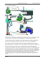
The slicing software is the first tool in the chain of 3D printing software. Slicing
software uses commonly used .STL files to create .gcode files.
.STL
.OBJ
.AMF
INPUT
SLICER
OUTPUT
.gcode
Gcode files contain instructions for the 3D printer on where, when, and how fast to
make movements. This is where choosing the right slicing software to optimize your
.STL, .OBJ or .AMF file for 3D printing becomes critical to successful printing.
Although the INFINITY 3D printer will work with any slicing software, we’ve
chosen to highlight MatterSlice in the instructions of this operations manual.
The .STL file is a 3D model file that can be exported by all common CAD and 3D
modeling software. The MatterSlice software then slices the .STL 3D model into
layers and print paths to create a 3D printable .gcode file.
8-Sep-14
7
Revolution 3D Printers
INFINITY 3D
MatterSlice includes very simple settings that allow you to easily refine prints. You
can create multiple configurations for changing printer setups including nozzle sizes
and desired print resolution. For ease of use we have pre-defined three Quality
Slice Settings and two Material settings in the MatterSlice program. These
configuration settings will appear when you select the INFINITY 3D printer. We
highly recommend starting with our pre-defined MatterSlice configurations for your
initial prints.
Should you choose to use another slicing software you must include the following
custom .gcode to the beginning of your slice file:
G90
;absolute positioning
G28 X0 Y0 ;move X/Y to min endstops
G28 Z0
;move Z to min endstops
G1 F900 Y60 ;move Y 60mm to miss the bed clip
G92 E0
;zero the extruded length
G1 F200 E3
;extrude 3mm of feed stock
G92 E0
;zero the extruded length again
G1 F7800
M117
[input_filename_base]; what will be displayed during print
Include this .gcode at the end of your file:
M104 S0
;extruder heater off
M140 S0
; bed heat off
G91
;relative positioning
G1 E-1 F300
;retract the filament a bit before lifting the nozzle
G1 Z+0.5 E-5 X-20 Y-20 F{travel_speed} ;move Z up a bit and retract filament
G28 X0 Y0
;move X/Y to min endstops, so the head is out of the
way
M84
;steppers off
G90
;absolute positioning
8-Sep-14
8
Revolution 3D Printers
INFINITY 3D
CAD and 3D Modeling Software
Currently Revolution 3D Printers is not distributing any CAD or 3D modeling
software packages. However, there are multiple free/libre software packages
available. Other common non-free CAD and 3D modeling software are also capable
of exporting the required .STL files. On some CAD and 3D modeling software you
will need to select millimetres as the output unit. If possible it is best to build your
3Ddesign in metric units rather than imperial units. MatterSlice requires .STL files
sized in millimetres. If an .STL with inches as units is loaded into the MatterSlice,
the model will be scaled much smaller than expected. The software listed below
outputs millimetres as the unit by default.
FreeCAD
Website: http://free-cad.sourceforge.net
FreeCAD is a great free/libre CAD application. Containing a full GUI for building CAD
models, FreeCAD is capable of creating simple to complex designs. STL files can
also easily be exported for use with 3D printing. FreeCAD is available for
GNU/Linux, Windows, and Mac. The latest development version is recommended.
Blender
Website: http://blender.org
The most widely used free/libre 3D modeling software, Blender is well documented
with tutorials available on the Blender.org website. Numerous video tutorials can be
also found online.
Shapesmith
Website: http://shapesmith.net
Shapesmith is a web based 3D modeling software. This means there is no required
software to get started designing models. Shapesmith is also a great choice for
anyone just starting out in CAD/ 3D modeling.
OpenSCAD
Website: http://openscad.org
OpenSCAD is another free/libre CAD software; however, different than FreeCAD, it
is script based. Rather than using a GUI to generate CAD designs, OpenSCAD CAD
designs are created using script based renderings. Operators with programming
experience would find this very useful. Also, OpenSCAD uses a simple script
language that is easy to learn for operators with little or no programming
experience.
8-Sep-14
9
Revolution 3D Printers
INFINITY 3D
Getting to know the INFINITY 3D Printer
Main Components Identification
Figure 2 Main Components Identification
For a full components list, refer to the Illustrated Parts Catalogue.
8-Sep-14
10
Revolution 3D Printers
INFINITY 3D
Full Graphic Display/Control Panel
Figure 3 Full Graphic Control/Display Panel
The Infinity 3D Full Graphic Display/Control panel allows for untethered printing and
thus eliminate the possibilities of a failed print due to the connection between a
computer and the printer timing out or simply failing. The full graphic
display/control panel also allows for many on the fly adjustments not available
when using a tethered connection. For example, you are able to increase or
decrease speed while printing using the Interface Knob. The control panel has a slot
on the LH side for inserting the SDcard (or micro adapter card) that is required for
untethered printing. Refer to the INFINITY 3D Quick Print Guide for use of the
display/control panel for printing. The Main Menu can be accessed by pressing down
on the Interface Knob and consists of the following:
Main Start Up Screen
Info Screen
Prepare
Disable steppers
Auto home
Preheat PLA
Preheat PLA 1
Preheat PLA 2
Preheat PLA 3
Preheat PLA ALL
Preheat PLA Bed
Preheat ABS
Preheat ABS 1
Preheat ABS 2
8-Sep-14
11
Revolution 3D Printers
INFINITY 3D
Preheat ABS 3
Preheat ABS ALL
Preheat ABS Bed
Cool down
Switch power off
Move axis
Move 10mm
Move 1mm
Move 0.1mm
Control
Temperature
Nozzle:
Nozzle2:
Nozzle3:
Bed:
Fan Speed:
Autotemp:
Min:
Max:
Fact:
PID-P:
PID-I:
PID-D:
PID-C:
Preheat PLA conf:
Fan Speed:
Nozzle:
Bed:
Preheat ABS conf:
Fan Speed:
Nozzle:
Bed:
Motion
Accel:
Vxy-jerk:
Vz-jerk:
Ve-jerk
Vmax x:
Vmax-y:
Vmax-z:
Vmax-e:
Vmin:
Vtrav min:
Amax z:
Amax y:
Amax x:
Amax e:
A-retract:
Xsteps/mm:
Ysteps/mm:
Zsteps/mm:
Esteps/mm:
LCD contrast
LCD contrast:
Restore failsafe
Print from SD
<list of the .gcode files on the SD card>
8-Sep-14
12
Revolution 3D Printers
INFINITY 3D
Figure 4 Single Professional All Metal Extruder
Single Professional All Metal Extruder
The INFINITY 3D printer incorporates many innovative features and well thought
out parts designed to take full advantage of the Single Professional All Metal
Extruder. The Infinity 3D fitted with the Professional Extruder can alleviate most of
this frustration by simplifying the filament changing process by utilising an easy
opening service door that offers continuous idler bearing spring preload adjustment
using 2 set screws.
The extruder assembly features an innovative “all metal” hot end that features a
detachable filament guide and nozzle module “DFGNM”. This design ensures easy to
change nozzles for a variety of filaments. As well as enabling you to work with
polycarbonates at temps between 280-315 degrees Celsius and future materials
that will require higher temperatures beyond what can be supported by other hot
end designs.
The 1:13 geared Nema-12 stepper motor and stainless steel 303 hobbed gear
offers another advantage for successful printing, it moves the heat of the motor
from long print runs, away from the filament drive teeth.
8-Sep-14
13
Revolution 3D Printers
INFINITY 3D
Figure 5 Quick Disconnect Extruder Plug
The Professional Extruder utilises a D-Sub connector located on the rear of the
extruder carriage assembly. This allows for the quick replacement of the extruder
assembly by simply removing three screws and unplugging from printer.
8-Sep-14
14
Revolution 3D Printers
INFINITY 3D
Heated Bed
Figure 6 Heated Bed
The heated bed is essential to creating high quality prints by reducing warping and
curling of the printed parts due to inconsistent cooling and shrinking. The heated
bed is controlled by the power wires connecting the +/- to the RAMPS board and a
thermistor controls when power is ON or OFF depending on the temperature
selected by the operator.
8-Sep-14
15
Revolution 3D Printers
INFINITY 3D
Power Supply
Figure 7 Power Supply
The Standard 12volt 30AMP power supply, mounted in the aft RH corner of the
frame, provides the DC voltage required to operate the printer. The power supply is
turned ON and OFF with a switch located on the front panel of the printer.
Figure 8 ON and OFF Switch
8-Sep-14
16
Revolution 3D Printers
INFINITY 3D
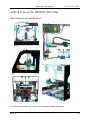
RAMPS Enclosure
Figure 9 RAMPS Enclosure
The RAMPS enclosure, located in the aft LH corner, was designed to provide a
convenient place to house all necessary electronics as well as provide proper
cooling of circuitry to ensure trouble free operation. On the LH side of the printer
there is an access hole, this is where the USB printer cable will plug into for
tethered printing (running printer direct from computer) as well as connection to a
computer for firmware updates. Always turn power off and unplug printer before
opening the case cover. The cover has the cooling fan attached, care should be
taken on removal that the wires are not stressed and on installation ensure correct
polarity for fan plug. As with all the hardware that is installed directly into any
plastic parts, use very little torque on installation.
8-Sep-14
17
Revolution 3D Printers
INFINITY 3D
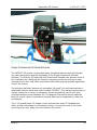
Axis Identification - XYZ +E Cartesian Robot
Figure 10 XYZ Cartesian Robot
The INFINITY 3D is a Cartesian robot, this means it moves in the XYZ axis in a
linear manner. The E axis can be considered the tool head as it is the extruder
motor which needs to be controlled to enable correct extrusion rates. Although not
all CAD programs use the same color standards for the axis, Revolution 3D Printers
opted to use the most common Green for the X-Axis, Blue for the Y-Axis and Red
for the Z-Axis with Yellow as the E(xtruder) axis. This color co-ordination standard
is important as throughout the Infinity 3D printer and these manuals it is used to
quickly and easily identify harness connections and parts. This is evident in the part
colors for the different axis parts.
8-Sep-14
18
Revolution 3D Printers
INFINITY 3D
Limit Switch Locations
Figure 11 Limit Switch Locations
Mechanical limit switches are strategically located to both aid in keeping the wiring
clean as well as to provide the least possibility of interference and trouble.
The X-Axis Limit switch is located on the X-Axis motor mount and is activated by
the tab on the aluminum extruder mount plate. This stop is not adjustable.
The Y-Axis Limit switch is located under the bed and is attached to the Linear
Bearing fitting on the LH back side, the stop located on the linear rod is adjustable.
Unlike the X and Y, the Z Axis Limit is an optical switch to provide extremely
accurate and repeatable limit location, alleviating the need for constant adjustment
and failed prints due to incorrect height adjustment. The Z-Axis stop is attached to
the back side of the LH Z-Axis motor mount. The stop for the Z-axis is adjustable to
accommodate varying sizes and lengths of hot ends, bed build plates or styles of
extruders/tool heads. The initial starting height when printing is critical to
successful printing, and is covered in further detail in Calibration, Alignment and
Tuning.
8-Sep-14
19
Revolution 3D Printers
INFINITY 3D
The Important First Layer
Before you start the first print it is worthwhile to talk about the importance of
getting the first layer right. As many have found through trial and error, if the first
layer is not the best it can be then it can lead to complete failure, parts detaching,
and warping. There are several techniques and recommendations to follow in order
to minimise the chance of this happening.
Proper filament extrusion
Before starting your print, make sure that the filament is able to flow through the
hot end of the extruder without any plugs or dust in the way. The same goes for
the filament feeder, blow out any dust or filament particles to ensure smooth
extrusion. Refer to the Quick Print Guide on how to properly set up filament before
every print.
Level Bed
Having a level bed is critical. If the distance between the nozzle tip and the bed
deviates by even a small amount it can result in either the material not lying down
on the bed (because the nozzle is too close and scrapes the bed instead), or the
material lying too high from the bed and not adhering correctly. Make sure to
change the level of the bed if you go between using blue painters tape and
hairspray as the blue painter’s tape adds to the height of the bed. Refer to the Bed
Levelling section in Maintaining Your Printer.
Higher temperature
The extruder hot-end and bed, if it is heated, can be made hotter for the first layer,
thus increasing the viscosity of the material being printed. If you find that your
filament is not adhering, even after printing a “skirt”, try increasing the extruder
multiplier or increasing the temperature. As a general rule, an additional 5°C is
recommended.
Lower speeds
Slowing down the extruder for the first layer reduces the forces applied to the
molten material as it emerges, reducing the chances of it being stretched too much
and not adhering correctly. 30% or 50% of the normal speed is recommended.
Speed can also be increased or decreased during the printing process using the
interface knob and display/control panel, or the speed multiplier in MatterControl.
Bed material
There are many surface adhering options out there, and preparing the right surface
can vastly improve first layer adhesion. For most filaments, a light coat of an
adhesive such as hairspray works well. If hairspray doesn’t work, for PLA, use PET,
Kapton, or blue painters tape. For ABS, use PET, Kapton tape with an ABS/acetone
glue.
8-Sep-14
20
Revolution 3D Printers
INFINITY 3D
ABS/Acetone Glue
Acetone is not included or required for the INFINITY 3D printer.
Acetone can cause skin irritation when prolonged skin contact occurs. It is
recommended to use acetone safe gloves when applying the ABS/acetone glue. Use
the ABS/acetone glue in a well-ventilated space. Leave the mixture bottle closed
except when applying to the bed. Acetone liquid and vapours are highly flammable.
Keep acetone away from open fames and high temperature sources, including the
3D printer. Read the warnings label on your purchased acetone packaging for
additional warnings.
Using an HDPE acetone safe bottle 200ml, fill the bottle 3/4 full with acetone. Now
cut eight, 75mm lengths of ABS filament and put them in the bottle with the
acetone. Allow the ABS filament to dissolve for 4-6 hours.
When applying the acetone/ABS mixture it will work best when the bed
temperature is below 60C. To apply the acetone/ABS mixture use an acid brush or
similar and brush onto the cool print surface to apply a thin layer of ABS. Generally
only one thin layer of the acetone/ABS solution is needed. However, if needed you
can apply multiple coats.
8-Sep-14
21
Revolution 3D Printers
INFINITY 3D
Maintaining Your 3D Printer
There is little maintenance needed in keeping your INFINITY 3D printer running.
Depending on your rate of use you will want to perform a quick check of your
printer every 2-4 weeks. The following maintenance guide lines will keep your
printer printing quality models.
Bed Levelling
The INFINITY 3D is completely assembled, calibrated and fine tuned so that you
can start printing right away. The bed levelling should not be disturbed as it is set
using very accurate equipment. Just in the case that the bed requires re-levelling,
such as movement during shipping, ensure you follow these instructions step by
step for best results:
1. Use the X-Axis levelling block provided in the tool kit. This block is used to
ensure that both the left and right sides of the x-axis assembly are
referenced (levelled) to the same height.
2. Level the x-axis by raising it using the Full Graphic Display/Control panel by
selecting prepare and then move axis until you can insert the block between
the top of the z-axis motor mount and the bottom of the x-axis mounts,
leave approximately 2-3 mm clearance between your block and the bottom
of the x-axis motor mounts on each side.
3. Now by manually turning the z-axis threaded rods counter-clockwise lower
each side until they just contact your levelling block. Ensuring this is done
accurately on each side will give you the best end results.
4. DO NOT move the z-axis motors manually from this point on.
5. With the x-axis now levelled, using the graphic/control display, select “auto
home” to get the axis motors to move in unison to their home positions.
6. DO NOT move the z-axis motors with the panel until levelling is
complete.
7. Select “Disable steppers” in the display menu.
8. Use the bed height calibration card provided in the tool kit for the following
adjustments.
9. When the distance between the build surface and the clean nozzle tip is
correct the calibration card tool will slide under with a slight bit of resistance.
10.Manually position the nozzle above one of the corners as close to the build
plate securing clip as possible.
11.Now check the clearance between the build surface and the nozzle tip with
the calibration card.
12.Use the provided wrench and allen key to adjust the levelling screw nearest
to the nozzle until this clearance is achieved.
13.Repeat steps 7-13 for each corner. Recheck all clearances until they all
match.
Note: If you are unable to or run out of spring pressure on the levelling
springs start by tightening the spring screws until 6-8 threads are visible past
the locknut or until any point of the heated bed just contacts the bed mount
8-Sep-14
22
Revolution 3D Printers
INFINITY 3D
plate. Adjust the coarse adjust Z-Axis stop by moving it up or down until
the nozzle has a clearance of approx 2-3 mm from the build plate. You will
need to “Auto home” each time you make an adjustment. You may need to
“Auto home” a few times if you make an adjustment upwards.
14. Repeat Steps 6-14 to level each corner.
Smooth Rods
Wipe the smooth steel rods with a clean rag or paper towel. The linear bearings
require very little lubricant. Apply a small amount of lightweight oil using needle
oiler directly to the rods.
Threaded Z-Axis Rods
Place a small amount of oil from needle oiler on the threaded rods to lubricate the
internal nut located in the x-axis mounts.
Hot End
The hot end should be kept clean of extruded plastic by removing melted plastic
strands with the tweezers. If melted plastic builds up on the hot end nozzle it can
be cleaned by gently scraping with tweezers all plastic while hot end is hot.
Electronics
The electronics case holding the RAMPS board may need to have dust blown out
occasionally. Power down the printer and use the provided 2.5MM driver to remove
the 4 M3 screws holding the lid to the enclosure. The fan is mounted to the lid and
connected to the Fan Extender board. Be careful with the fan cable during removal.
Once removed use short bursts of compressed air to blow out any dust or debris.
Plug in the lid fan paying attention to polarity and reattach the lid.
Changing nozzles
The INFINITY 3D printer ships with a standard 0.35mm nozzle size Hot-End which
allows small layer resolution and up to 0.35mm layers. Although the 0.35mm
nozzle will be perfect for most printing applications Revolution 3D Printers also
offers smaller and larger nozzle sizes.
8-Sep-14
23
Revolution 3D Printers
INFINITY 3D
Support
For common technical support questions for your INFINITY 3D printer visit
Revolution3DPrinters.com
If you have further questions,
For Technical Assistance call: 1-877-269-5510, ext 2
Email: [email protected]
Please completely read this manual before contacting for support questions or help.
8-Sep-14
24