1
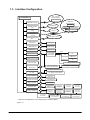
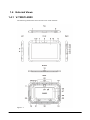
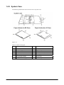
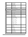
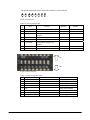
CASIO
V-T500/V-N500 Series
Hardware Manual
(Version 1.07)
CASIO Computer Co., Ltd.
Copyright © 2013. All rights reserved.
June 2013
Table of the Contents
Chapter 1.
Introduction
1.1
Feature
1.2
Model Configuration
1.3
Interface Configuration
1.4
External Views
1.4.1
V-T500/V-N500
1.4.2
System Case
1.4.3
LAN/USB Cradle, HA-M62IO
1.4.4
Cradle-type Battery Charger, HA-M30CHG
1.4.5
Dual Battery Charger, HA-M32DCHG
1.4.6
In-vehicle Adaptor, HA-M37CAC
1.4.7
Rechargeable Battery Pack, HA-M20BAT
1.4.8
AC Adaptor, AD-S90190C-N5
1.4.9
AC Adaptor, AD-S36120A-N
1.4.10 Digitizer Pen, AD-S36120A-N
1.4.11 Hand Belt, HA-M95HB
1.4.12 Screen Cover, HA-M98DC
1.4.13 Neck Strap, HA-M97ST
Chapter 2.
Basic Specifications
2.1
V-T500/V-N500
2.2
LAN/USB Cradle, HA-M62IO
2.3
Cradle-type Battery Charger, HA-M30CHG
2.4
Dual Battery Charger, HA-M32DCHG
2.5
In-vehicle Adaptor, HA-M37CAC
2.6
Rechargeable Battery Pack, HA-M20BAT
2.7
AC Adaptors
Chapter 3.
Quality Specifications
3.1
Environmental Capabilities
3.1.1
V-T500/V-N500
3.1.2
LAN/USB Cradle, HA-M62IO
3.1.3
Cradle-type Battery Charger, HA-M30CHG
3.1.4
Dual Battery Charger, HA-M32DCHG
3.1.5
In-vehicle Adaptor, HA-M37CAC
3.1.6
Rechargeable Battery Pack, HA-M20BAT
3.1.7
AC Adaptor
3.2
Electrical Specifications
3.2.1
V-T500/V-N500
3.2.2
LAN/USB Cradle, HA-M62IO
3.2.3
Cradle-type Battery Charger, HA-M30CHG
3.2.4
Dual Battery Charger, HA-M32DCHG
3.2.5
In-vehicle Adaptor, HA-M37CAC
3.2.6
AC Adaptors, AD-S90190C-N5/AD-S36120A-N
3.3
Mechanical Specifications
3.3.1
V-T500/V-N500
3.3.2
LAN/USB Cradle, HA-M62IO
3.3.3
Cradle-type Battery Charge, HA-M30CHG
2
5
5
6
8
9
9
11
12
13
14
15
15
16
16
17
17
18
18
19
19
29
31
33
34
35
35
36
36
36
36
37
37
38
38
39
40
40
40
41
41
42
42
43
43
44
44
3.3.4
Dual Battery Charger, HA-M32DCHG
3.3.5
In-vehicle Adaptor, HA-M37CAC
3.3.6
Rechargeable Battery Pack, HA-M20BAT
3.3.7
AC Adaptor
3.4
Compliance
3.4.1
V-T500/V-N500
3.4.2
LAN/USB Cradle, HA-M62IO
3.4.3
Cradle-type Battery Charger, HA-M30CHG
3.4.4
Dual Battery Charger, HA-M32DCHG
3.4.5
Rechargeable Battery Pack, HA-M20BAT
3.1
Performance Reference
3.1.1
Handling Contactless Smart Card
Chapter 4.
Precautions
4.1
Precautions for Handling and Operating V-T500/V-N500
4.1.1
About Recharging, Supplying Power, and Battery
4.1.2
Others
4.2
Storage
4.3
Safety Precautions
Chapter 5.
Maintenance
Installation
Chapter 6.
3
45
45
46
46
47
47
48
48
49
50
51
51
58
58
58
58
59
59
59
59
No part of this document may be produced or transmitted in any form or by any means, electronic or
mechanical, for any purpose, without the express written permission of CASIO Computer Co., Ltd. in
Tokyo Japan. Information in this document is subject to change without advance notice. CASIO
Computer Co., Ltd. makes no representations or warranties with respect to the contents or use of this
manual and specifically disclaims any express or implied warranties of merchantability or fitness for
any particular purpose.
© 2013CASIO Computer Co., Ltd. All rights reserved.
4
1. Introduction
1.1 Feature
Platform
• Android 4.0
Communication capabilities
• Built-in wireless LAN module (conforming to IEEE802.11a, IEEE802.11b, IEEE802.11g, and
IEEE802.11n)
• Bluetooth® Version 4.0 (Class2)
• USB version 1.1 (Host/Client)
• NFC
Dimensions and weight
• Outer dimensions
• Weight
: Approx. 210(W) × 14.4(D) ×190(H) mm
: 780 g
Shock resistance and splash-proof
• Drop resistance
: 1.0 m
CPU and memory capacity
• CPU
• Memory capacity
OMAP 1.5GHz Dual Core
RAM
: 1GB
FROM : 16GB
5
1.2 Model Configuration
Table 1.1 Model configuration
Model Number
V-T500-E
V-T500-GE
V-N500-E
V-N500-EF
V-N500-GEF
WWAN
System Case
GSM / W-CDMA
GSM / W-CDMA
Yes
-
6
Remarks
Table 1.2 Option List
Model Number
Description
HA-M62IO
HA-M30CHG
HA-M32DCHG
AD-S36120A-N
AD-S90190C-N5
HA-M20BAT
AC-CORD-EU
AC-CORD-US
AC-CORD-TW
AC-CORD-KR
AC-CORD-AU
AC-CORD2-EU
AC-CORD2-US
AC-CORD2-TW
AC-CORD2-KR
AC-CORD2-AU
HA-M37CAC
HA-M96PEN
HA-M95HB
HA-M98DC
HA-M97ST
HA-M99CAS
LAN/USB Cradle
Cradle-type Battery Charger
Dual Battery Charger
AC Adaptor (Cradle, The Terminal)
AC Adaptor (Dual Battery Charger)
Rechargeable Battery Pack
AC Power Cord
(Cradle, The Terminal)
AC Power Cord
(Dual Battery Charger)
Remarks
for Europe
for North America
for Taiwan
for Korea
for Australia
for Europe
for North America
for Taiwan
for Korea
for Australia
In-vehicle Adaptor
Digitizer Pen
Hand Belt
Screen Cover
Neck Strap
System Case
Table 1.3 Accessories
Item
AC Adaptor
AC Power Cord
Rechargeable Battery Pack
Rechargeable Battery
System Case
Paper Holder (for B5 size)
Paper Holder (for A5 size)
microSD Eject Jig
Printed Matter of WEEE
Printed Matter of Rechargeable Battery
V-T500-E
V-T500-GE
Yes
Yes
Yes
Yes
Yes
Yes
Yes
7
V-N500-EF
V-N500-GEF
Yes
Yes
Yes
Yes
Yes
Yes
Yes
Yes
Yes
V-N500-E
Yes
Yes
Yes
Yes
Yes
Yes
Yes
Yes
Yes
Yes
1.3 Interface Configuration
802.11a/b/g/n
Support Products
V-T500/N500
Access Point
Bluetooth
Support Products
Scanner
IEEE802.11a/b/g/n
Mobilephone
GSM/W-CDMA
LTE
Headset
PC
Satellite
GPS
Bluetooth
(Ver4.0)
Pocket Printer
V-T500/V-N500
ISO 14443, 15693
NFC
USB A Port
USB Device
USB miniB Port
USB Device
HDMI Port
HDMI Device
Communication Port
LAN Cradle
HA-M62IO
LAN
PC
USB
USB Device
Configuration Switch
USB Client
Extension Port
PC
AC Adaptor AD-S36120A
Cradle-type Battery
Charger HA-M30CHG
Power Feed
AC Adaptor AD-S36120A
Car Adaptor HA-M37CAC
DC Jack
AC Adaptor AD-S36120A
SD Card Slot
SD Card
microSD Card Slot
microSD Card
SAM Card Slot
SAM Card
SIM Card Slot
SIM Card
Rechargeable
Battery Pack
HA-M20BAT
Battery Terminal
AC Adaptor
AD-S90190C
Rechargeable
Battery Pack
HA-M20BAT
Rechargeable
Battery Pack
HA-M20BAT
Rechargeable
Battery Pack
HA-M20BAT
Rechargeable
Battery Pack
HA-M20BAT
Rechargeable
Battery Pack
HA-M20BAT
Rechargeable
Battery Pack
HA-M20BAT
Dual Battery Charger
HA-M32DCHG
* Interface configuration varies depending on model number.
Figure 1.1
8
Dual Battery Charger
HA-M32DCHG
Dual Battery Charger
HA-M32DCHG
1.4 External Views
1.4.1 V-T500/V-N500
The following illustrations show external views of the terminal.
Figure 1.2
9
Table 1.4 Name and function of each part
No.
Name
1
2
3
4
5
Power Key
Sound Volume Key
HDM Connector
SD Card Slot
Recharge Indicator LED
6
7
Notice Indicator LED
Illuminance Sensor
8
9
Inner Camera
Display (Touch Panel)
10
11
Microphone
NFC Reading Part
Key to turn on and off of the power of the terminal.
To control of sound volume.
For connection with external MIDI equipment.
Slot for SD card
Lit up with Orange: Under recharge.
Blinking with Orange: Battery power is 0% to 5%.
Lit up with Green: Recharge completed.
Lit up with Red: Abnormal battery pack or out of rechargeable temperature
range.
Also lit up Green for about 1 second when power turn to ON..
LED to activate applications.
Automatically adjusts the back light brightness depending on the ambient
luminosity.
For capturing images and shooting pictures.
Operatable by finger touch and allows text input or screen handling by
optional pen-type digitizer.
For input of voice.
Card data is read by shading this part with card.
12
13
14
15
Button, Function A
Button, Function B
Screen Lock Button
USB A Port
Button to activate applications.
Button to activate applications.
Pushing this button allow to lock or unlock the screen.
To connect the terminal with external USB equipment.
16
17
18
19
20
21
22
23
24
25
26
27
USB miniB Port
DC Jack
Charge/Communication
Terminal
Mount
Reset Switch
Outer Camera
Catch for Screen Cover
Catch for Pen Holder
Extension Slot
SAM Card Slot
SIM Card Slot
Configuration Switch
28
microSD Card Slot
29
30
31
32
Buzzer
Speaker (L)
Speaker (R)
Rechargeable Battery
Pack Cover
Rechargeable Battery
Pack Cover Lock Switch
To connect the terminal with external USB equipment.
To connect the terminal AC Adaptor or In-vehicle adaptor.
To change battery in the terminal put on the cradle, and use for USB/LAN
communication.
To attach system case, hand belt and neck strap.
The terminal is reset by push of this switch.
For capturing images and shooting pictures.
To attach screen cover.
To attach pen holder of pen-type digitizer.
Provided for extension of system.
To insert SAM card. (removal of rechargeable battery pack is required.)
To insert SIM card. (removal of rechargeable battery pack is required.)
To configure start-up conditions of the terminal, system administrator use
only. Users shall refrain from touching this switch.
To insert microSD card.
(removal of rechargeable battery pack is required.)
For generation of beeping buzzer.
For sound output.
For sound output.
Rechargeable battery pack to be installed inside the cover.
33
Description
For open/close of rechargeable battery pack cover by rotating this part.
10
1.4.2 System Case
The following illustrations show external views of System Case.
Figure 1.3
Table 1.5 Name of each part
No.
1
2
3
4
5
6
7
Name
Fastener
Unit Holder (Upper)
Pen Holder
Unit Holder (Lower)
Magnetic Sensor
Pen-type Digitizer Holder
Paper Holder Fixture (Upper)
No.
8
9
10
11
12
13
14
11
Name
Business Card Read Area
Stopper for Flip'n Shoot
Business Card Holder
Paper Holder Fixture (Lower)
Notch (Upper)
Notch (Lower)
Paper Holding Belt
1.4.3 LAN/USB Cradle, HA-M62IO
The following illustrations show the external views of LAN/USB Cradle, HA-M62IO.
Figure 1.4
Table 1.6 Name and function of each part
No.
1
2
3
4
5
6
7
8
9
Name
Power Supply and
Communication Terminals
Power Indicator LED
Description
Terminals for power supply and data communication use.
Indicates status of power supply and normal/abnormal installation of the
terminal.
Lit up with Red: Power is on. The terminal is not installed.
Lit up with Green: Power is on. The terminal is correctly installed.
Light-out: Power is off.
Power Switch
Switch to turn ON/OFF the power.
AC Adaptor Jack
Jack to connect output of optional AC Adaptor to supply power.
Selection Switch
Switch to select USB host, USB Client, or LAN.
To use host, switch to A side, and switch to B side for client.
LAN Port
Port to connect LAN cable to enable connection with PC or HUB to transfer
(down/up loading) system data, file data.
LAN Communication Status Indicates operational status of LAN.
Indicator LED
Light-out: Communication is not being executed.
Blinking: Communication is being executed.
LAN Connection Status
Indicates LAN connection status.
Indicator LED
Light-out: LAN cable connection is abnormal.
Lit up with Orange: LAN cable connectionism abnormal.
Port for USB Host
To connect supported USB peripheral device.
10 Port for USB Client
Port to connect USB cable to enable connection with PC or HUB to transfer
(down/up loading) system data, file data. Installation of exclusive driver
software in PC, prior to use, is required.
12
1.4.4 Cradle-type Battery Charger, HA-M30CHG
The following illustrations show the external views of Cradle-type Battery Charger, HA-M30CHG.
Figure 1.5
Table 1.7 Name and function of each part
No.
1
2
3
4
Name
Description
Power Supply Terminals Terminals for power supply.
Power Indicator LED Indicates status of power supply and normal/abnormal installation of the terminal.
Lit up with Red: Power is on. The terminal is not installed.
Lit up with Green: Power is on. The terminal is correctly installed.
Power Switch
Switch to turn on/off the power of the terminal.
AC Adaptor Jack
Jack to connect output of optional AC Adaptor to supply power.
13
1.4.5 Dual Battery Charger, HA-M32DCHG
The following illustrations show the external views of Dual Battery Charger, HA-M32DCHG.
Figure 1.6
Table 1.8 Name and function of each part
No.
1
2
3
4
5
Name
Description
Dual Battery Charger Jack
Recharge Status Indicator LED
For cable to connect another Dual Battery Charger.
Indicates status of recharging Rechargeable Battery Pack..
Lit up with Green: Charging complete.
Lit up with Red: Battery pack problem or standby due to the surrounding
temperature being beyond the specified temperature range
(Approximately 0°C to 40°C) (charging resumes when the temperature
reaches the range.)
Lit up with Orange: Charging
Light-out: Not charging
Battery Power Supply Terminal Terminal to connect Rechargeable Battery Pack..
AC Adaptor Jack
Jack to connect output of optional AC Adaptor to supply power.
Mounting Part for attachment to To connect 2 or more Dual Battery Chargers, fix attachment to these
connect additional Dual Battery parts.
Charger.
14
1.4.6 In-vehicle Adaptor, HA-M37CAC
The following illustration shows the external view of In-vehicle Adaptor, HA-M37CAC.
Figure 1.7
1.4.7 Rechargeable Battery Pack, HA-M20BAT
The following illustration shows the external view of Rechargeable Battery Pack, HA-M20BAT.
Figure 1.8
15
1.4.8 AC Adaptor, AD-S90190C-N5
The following illustration shows the external view of the AC Adaptor, AD-S90190C-N5.
Figure 1.9
1.4.9 AC Adaptor, AD-S36120A-N
The following illustration shows the external view of the AC Adaptor, AD-S36120A-N.
Figure 1.10
16
1.4.10 Digitizer Pen, AD-S36120A-N
The following illustration shows the external view of Digitizer Pen, HA-M96PEN.
Figure 1.11
Table 1.9 Name and function of each part
No.
1
2
3
4
5
Name
Pen Nibs
Quick Button 1
Quick Button 2
Strap Hole
Cap
Description
For touch display.
Button which can use by applications. (It is not set up in the initial state.)
Button which can use by applications. (It is not set up in the initial state.)
To attach the strap including in a package.
To install/remove a dry cell by open/close this part.
1.4.11 Hand Belt, HA-M95HB
The following illustration shows the external view of Hand Belt, HA-M95HB.
Figure 1.12
17
1.4.12 Screen Cover, HA-M98DC
The following illustration shows the external view of Screen Cover, HA-M98DC.
Figure 1.13
1.4.13 Neck Strap, HA-M97ST
The following illustration shows the external view of Neck Strap, HA-M97ST.
Figure 1.14
18
2. Basic Specifications
2.1 V-T500/V-N500
The basic specifications of V-T-500/V-N500 series (all models) are shown below.
Table 2.1
Item
Specifications
CPU
Platform
OMAP 1.5GHz Dual Core
Android 4.0
Memory
RAM: 1GB
FROM: 16GB
Remarks
Display
Method
Screen Size
ISP method TFT Color LCD
10.1 inch
Number of Dots
Horizontal:
1280 dots × Vertical: 800 dots (VGA)
Horizontal: 0.16957mm × Vertical: 0.1695mm
16.7 M
Dot Pitch
Graduation
Back Light
Viewing Angle
Touch Panel
LED Back light
80°
Capacitive touch panel with Multi-Touch
Input: Pen-type digitizer.
Contrast: 10 or more
Indicators
LED
1 × 2-color, 1 × 3-color LED
Input
Keys and Buttons
Power, Functions A & B, Sound Volume, and
Screen Lock.
Bluetooth Communication, Class2
Standard
BluetoothR Specification Ver.4.0
Communication System
Spread Spectrum Communication System
Spread Modulation
FHSS:
Frequency Hopping Spread Spectrum Method
GFSK (1Mbps), Π/4-dqpsk(2Mbps), 8-DPSK
(3Mbps)
Low energy mode: GFSK only
F1D, G1D
Low energy mode: FID only
2.400GHz to 2.4835GHz
Approx. 5 meters
Modulation Method
Radio Wave Mode
Frequency
Communication Range
Continue
19
Varies depending on
conditions of radio wave
and environment.
Number of Channels
Channel Separation
Channel Band Width
Out put
WLAN 802.11a/b/g/n
Standard
Communication System
Spread Modulation
Modulation Method
Radio Wave Mode
Frequency
Transfer Rate
Communication Range
Number of Channels
79
1MHz
1MHz (2MHz for Low Frequency)
4dBm Max. (Power Class 2)
IEEE 802.11a/b/g/n
Spread Spectrum Communication System
802.11a/g/n: OFDM
(Orthogonal Frequency Division Multiplexing)
802.11b:
DSSS (Direct Sequence Spread Spectrum)
BPSK, QPSK, CCK, 16QAM, 64QAM
802.11a/n: D1D,G1D
802.11b/g: G1D
<Center frequency>
IEEE802.11a/n
W52:36/40/44/48ch (5.18GHz to5.24GHz)
W53:52/56/60/64ch (5.26GHz to 5.32GHz)
W56:100/104/108/112/116/120/124/128/132
/136/140ch (5.50GHz to 5.70GHz)
IEEE802.11b
ch.1 to ch.14 (2.412GHz to 2.484Ghz)
IEEE802.11g/n
ch.1 to ch.13 (2.412GHz to 2.472Ghz)
<Frequency range>
IEEE802.11a/n
5.15GHz to 5.35GHz (W52, W53)
5.47GHz to 5.725GHz (W56)
IEEE802.11b
2.400GHz to 2.497GHz
IEEE802.11g/n
2.400GHz to 2.4835GHz
802.11a/g: up to 54Mbps
802.11b: up to 11Mbps
802.11n: up to 72Mbps
802.11b/g/n: 50m (in-door), 150 m (out-door)
(2.4GHz band for /n)
802.11a/n: 30m (in-door), 150 m (out-door)
(5GHz band for /n)
802.11a/n:
W52:4,W53:4,W56:11 (n:5GHz band)
802.11b: 14
802.11g/n: 13 (n:2.4GHz band)
Continue
20
Varies depending on
operating environmentand
transfer rate.
Channel Separation
802.11a/n: 20MHz
802.11b/g/n: 5MHz
Channel Band Width
Out put
802.11a/b/g/n: 20MHz
802.11a: 12.0dBm Min. Typical 13.5dBm
(at 54Mbps)
802.11b: 17.0dBm Min. Typical 18dBm
(at 11Mbps)
802.11g: 12.0dBm Min. Typical 14dBm
(at 54Mbps)
802.11n: 11.0dBm Min. Typical 12.5dBm
(at 72Mbps)
Roaming between multiple numbers of access
points.
Other Function
GSM
Standard
3GPP release99
Communication
functionality
Data transfer
Packet data
Modulation Method
Radio Wave Mode
Frequency range
No. of Channels
Downlink: 236.8kbps
Uplink: 236.8kbps
GSM/GPRS/EDGE
GSM850:
- 248KGXW (GPRS), 248KG7W (EDGE)
GSM900:
- 248KGXW (GPRS), 248KG7W (EDGE)
GSM1800:
- 248KGXW (GPRS), 248KG7W (EDGE)
GSM1900:
- 248KGXW (GPRS), 248KG7W (EDGE)
GSM850:
- Uplink: 824 - 849MHz
- Downlink: 869 - 894MHz
EGSM900:
- Uplink: 880 - 915MHz
- Downlink: 925 - 960MHz
DCS1800:
- Uplink: 1710 - 1785MHz
- Downlink: 1805 - 1880MHz
PCS1900:
- Uplink: 1850 - 1910MHz
- Downlink: 1930 - 1990MHz
GSM850: 124
EGSM900: 174
DCS1800: 374
PCS1900: 299
Continue
21
by Access Point
Channel spacing
Channel band width
Output power
GSM850: 45MHz
EGSM900: 45MHz
DCS1800: 95MHz
PCS1900: 80MHz
GSM850: 25×2 MHz
EGSM900: 35×2 MHz
DCS1800: 75×2 MHz
PCS1900: 60×2 MHz
33dBm (850/900MHz bands)
30dBm (1800/1900MHz bands)
W-CDMA
Standard
Communication
functionality
Data transfer
Modulation Method
Radio Wave Mode
Frequency range
No. of Channels
Channel spacing
Channel band width
Output power
UMTS/W-CDMA:3GPP release99
HSDPA:3GPP release5
Packet data
Downlink: 14.4Mbps
Uplink: 5.76Mbps
UMTS/HSDPA/HSUPA
Band I: 4M19F9W
Band V: 4M19F9W
Band VI: 4M19F9W
Band VIII: 4M15F9W
Band I:
- Uplink: 1920 - 1980MHz
- Downlink: 2110 - 2170MHz
Band V
- Uplink: 824 - 849MHz
- Downlink: 869 - 894MHz
Band VI
- Uplink: 830 - 840MHz
- Downlink: 875 - 885MHz
Band VIII
- Uplink: 880 - 915MHz
- Downlink: 925 - 965MHz
Band I: 277
Band V: 108
Band VI: 29
Band VIII: 152
Band I: 190MHz
Band V: 45MHz
Band VI: 45MHz
Band VIII: 45MHz
Band I: 60×2 MHz
Band V: 25×2 MHz
Band VI: 10×2 MHz
Band VIII: 35×2 MHz
24dBm
Continue
22
GPS
General Specifications
16-channel receiver, L1 1575.42MHz, C/A code
Positioning Method
Sensitivity
Standalone-GPS (S-GPS)
Acquisition sensitivity: -146dBm
Tracking Sensitivity: -162dBm
SIM
Standard
General Specifications
ISO 7816 IC Card Standard
SIM Card with 3V, 1.8V is supported.
Carrier Frequency
Antenna
Operating Magnetic Field
13.56MHz ±7kHz
Magnetic loop antenna
Output magnetic field intensity at contact to case.
1.5A/m or more
NFC
Bit Rate
Modulation Method
Modulation Factor
Readout Distance
Readout Distance
(Reference)
Readout area
Communication
Protocol
Output magnetic field intensity at 50mm from
case.
0.15A/m or more.
ISO14443 Type A: 106kbps
ISO14443 Type B: 106kbps
Felica: 212kbps,424kbps
ISO15693: 1.65kbps
ASK
10% modulation, 100% modulation
ISO14443 Type A/B, FeliCa:
0mm (Contact to back face of Card)
ISO15693:
0mm to 40mm Max.
0mm (Contact to back face of Card)
ISO15693 (Size: 85×54 mm): 40mm (for rear
side)
ISO15693 (Size: 4mm Ø): 2mm
15mm×15mm (Depends on types of card/tag)
Types of IC card
Standard
Support
performance verified
ISO14443
Yes
MIFARE Standard/
Type A
MIFARE Ultralight
ISO14443
Yes
JICSAP
Type B
FeliCa
Yes
FeliCa Standard
(JIS X 6319)
Continue
23
Measurement method:
ISO10373-6 (JIS X
6305-6)
Measurement method:
ISO18047-3 (JIS X
6305-6)
Refer to Figure 1.2 for
reading position.
For reading position,
refer to Figure 1.2.
Varies depending on
design of tag antenna.
ISO15693
Yes
ISO18092
Communication
between terminals
ISO18092
Card mode
-
I-CODE SLI
/I-CODE SLI-S
/I-CODE SLI-L
/my-d V 10 plain
/my-d Light
/Tag-it plus (See note1)
/Tag-it pro
/Tag-it standard
When data is
written into Tag-it,
exception error will
occur even if it is
succeeded to write.
Because of that, it's
necessary to
compare the data
(before writing)
with the data (after
writing).
Software
unsupported.
-
Note:
1. Some of the commands remain unsupported.
Prior-verification before introduction of this system is required because cards deviating from ISO
standard exist.
24
Item
Specifications
Remarks
SAM
Standard
General Specification
SD Card Slot
microSD Card Slot
Extension Port
USB
Connector Type
Connector Type
Host
Transfer Rate
Bus Power Output
Client
Transfer Rate
ISO 7816 IC Card Standard
SAM card of 1.8V/3V/5V are supported.
Supporting SDHC/SDIO cards
Supporting SDHC card
A
miniB
Full speed (12Mbps)
Low speed (1.5Mbps)
High speed (480Mbps)
5V/500mA Max
Full speed (12Mbps)
High speed (480Mbps)
Cradle Pin
Pin Layout
Pin Assignment
Camera
Effective Pixels
Image Sensor
Aperture
Focal Length
Focus Distance
LED Light
Speaker
Microphone
Buzzer
Magnetic Sensor
Oparation mode switch
Continue
Refer to Figure 2.1.
Refer to Table 2.2.
Approx. 5M Pixels (2592×1944 pixels)
1/4.0 type, CMOS Image Sensor
F2.8 ±5%
f = 3.4mm ±5%
10cm to infinity
29.4072 Candela/Square meter
Alarm, etc.
Voice input
Voice output
Available
See Figure 2.2, Table 2.3
25
At steady lighting
The pin layout below shows when the terminal is viewed at the
1
2
3
4
5
6
7
8
Figure 2.1 Pin layout
Table 2.2 Pin assignment table
Pin
Name
Function
No.
1 GND
GND
2 USB_ID
To switch USB to Host or Client.
3 V CRADLE
Recharge/Power Supply to The
Terminal.
4 D+
USB D+
5 DUSB D6 V CRADLE
Recharge/Power Supply to The
Terminal.
7 NONE
8 GND
GND
Direction
OUT
-
Remarks
Output from Cradle
IN/OUT
IN/OUT
-
ON
OFF
Figure 2.2 Switch layout
Table 2.3 Switch assignment table
No.
Initial switch state
Function
1 ON
2 ON
3 ON
4 ON
5 ON
6 OFF
7 OFF
Operation mode switch
8 OFF
26
Remarks
Setting change disabled
Setting change disabled
Setting change disabled
Setting change disabled
Setting change disabled
Setting change disabled
Setting change disabled
Item
Power Supply
Main battery
Backup battery
Operating Time
Specifications
Remarks
Lithium Ion Polymer Rechargeable Battery
1 × Lithium Ion Secondary Battery
Approx. 10 hours
WWAN standby: Approx. 150 hours
WWAN continuous communication:
Approx. 2 hours
Back-up Time
(Backup battery only)
Back-up Time
(Main + Backup
battery)
Main Battery Recharge
Time
RAM: 10 minutes
RTC: Over 72 hours
RAM: 72 hours
Recharge Specification
Backup battery
Recharge Time
Refer to Table 2.4.
Approx. 6 hours
Backup battery
Specification
Nominal Capacity of
Backup battery
Recharge Control of
Backup battery
Built-in type
Repeating below operation:
Data communication: 1 min.
Playback of video: 1 min.
Reference to screen: 3 min.
Stand-by (screen off): 10 min.
Normal temperature
New battery pack
Screen: OFF
WWAN power: ON
Normal temperature
New battery pack
Signal strength: good
Screen: ON
At full-charge of backup battery
under normal temperature.
After generation of battery-low
alarm
Approx. 6 hours
Normal temperature
LAN /USB Cradle, AC adaptor
and, Cradle-type Battery Charger
supplies power to the terminal
and recharge battery at same
time.
Time to full-charge of backup
battery with main battery being
set under normal temperature.
510mAh
Conditions
Powered by Cradle, AC
adaptor.
Recharge by main battery.
(The terminal power: ON)
Recharge by main battery.
(The terminal power:
OFF)
27
Availability of
backup battery
recharge
Yes
Yes
No
Table 2.4 Recharge Specification
Recharging method
LAN/USB Cradle (HA-M62IO)
Cradle-type Charger (HA-M30CHG)
Conditions for start of
recharge
Accessories in the left column
are attached to the terminal.
28
Behavior after completion of
recharge
Recharge will automatically start
when the battery voltage made
lower than certain level.
2.2 LAN/USB Cradle, HA-M62IO
The following table is for the basic specifications of LAN/USB Cradle, HA-M62IO.
Table 2.5
Item
USB Client
Standard
Transfer Rate
Pin Layout
Pin Assignment Table
Connector
Specifications
Remarks
Conforming to USB Ver.2.0
Full Speed (12Mbps)
High Speed (480Mbps)
Refer to Figure 2.3.
Refer to Table 2.6.
2
1
4
3
1. VBus
2. -Data (D)
3. +Data (D+)
4. GND
USB Connector: B Type
USB Host
Standard
Transfer Rate
Bus Power Output
Connector
Conforming to USB Ver.2.0
Full Speed (12Mbps)
Low Speed (1.5Mbps)
High Speed (480Mbps)
5V ±5%, 500mA Max.
1 2 3 4
1. VBus
2. –Data (D-)
3. +Data (D+)
4. GND
USB Connector A Type
LAN
Communication Protocol
Media Type
AC Adaptor Input
Input Voltage
Current Consumption
Applicable AC Adaptor
Continue
Conforming to IEEE802.3
10base-T/100base-TX , auto-change
DC 12V ±5%
DC12V 3.0A Max.
AD-S36120A-N
29
Power feed under
transferring data
Recharge/Power Supply
Method
Hybrid method of contact and
contactless type.
Method: Inductive coupling type
Output voltage: DC12V ±5%
Output Current: DC12V 2.0A.
Constant Voltage with Current Limiter
Approx. 6 hours
Contactless
Contact Zone
Recharge Method
Recharge Time
By built-in recharge circuitry
By built-in recharge circuitry
The figure seen from the top.
1
2
3
4
5
6
7
8
Figure 2.3 Pin layout
Table 2.6 Pin assignment table
Pin
Name
Function
No.
1
GND
GND
2
USB_ID
To switch USB to Host or Client.
3
V CRADLE
Recharge/Power Supply to The Terminal.
4
D+
USB D+
5
DUSB D6
V CRADLE
Recharge/Power Supply to The Terminal.
7
NONE
8
GND
GND
Direction
OUT
IN/OUT
IN/OUT
-
Remarks
Output from Cradle
-
Dimensions and Weight
Table 2.7
Item
Dimensions
Weight (g)
Specification
Approx. 292(W) × 98.5(D) × 64(H) mm
Approx. 332 g
30
Remarks
2.3 Cradle-type Battery Charger, HA-M30CHG
The following table is for the basic specifications of Cradle-type Battery Charger, HA-M30CG.
Table 2.8
Item
Specifications
AC Adaptor Input
Input Voltage
Consumption Current
Applicable AC Adaptor
Recharge/Power Supply
Method
DC12V ±5%
DC12V 3.0A Max.
AD-S36120A-N
Hybrid method of contact and
contactless type.
Method: Inductive coupling type
Output voltage: DC12V ±5%
Output Current: DC12V 2.0A.
Constant Voltage with Current
Limiter
Approx. 6 hours
Refer to Figure 2.4.
Refer to Table 2.9.
Contactless
Contact Zone
Recharge Method
Recharge Time
Pin Layout
Pin Assignment Table
Remarks
Power feed under transferring data.
By built-in recharge circuitry.
By built-in recharge circuitry.
The figure seen from the top.
1
2
3
4
5
6
7
8
Figure 2.4 Pin layout
Table 2.9 Pin assignment table
Pin
Name
Function
No.
1
GND
GND
2
NONE
3
V CRADLE
Recharge/Power Supply to The Terminal.
4
NONE
5
NONE
6
V CRADLE
Recharge/Power Supply to The Terminal.
7
NONE
8
GND
GND
31
Direction
-
-
Remarks
Dimensions and Weight
Table 2.10
Item
Dimensions
Weight (g)
Specification
Approx. 292(W) × 98.5(D) × 64(H) mm
Approx. 297 g
32
Remarks
2.4 Dual Battery Charger, HA-M32DCHG
The following table is for the basic specifications of Dual Battery Charger, HA-M32DCHG.
Table 2.11
Item
Charge
Charge Method
Recharge Time
Power Supply
Consumption Current
Useable Temperature
Useable Humidity
Number of Connectable
Units
Specifications
Current Voltage/Constant Current Method
For 1 battery pack only set: approx. 4 hours
For 2 battery pack set: approx. 6 hours
Remarks
With built-in current limiter.
Normal temperature
Recharge 2 battery packs
together.
AD-S90190C-N5
1 unit alone: approx. 1.10A
3 units connected together: approx. 3.0A
Approx. 0°C to 40°C
Approx. 30% to 80%
3 units Max.
Dimensions and Weight
Table 2.12
Item
Dimensions
Weight (g)
Specification
Approx. 196(W) × 60(D) × 55(H) mm
Approx. 242 g
33
Remarks
Excluding a connecting plate.
2.5 In-vehicle Adaptor, HA-M37CAC
The following table is for the basic specifications of In-vehicle Adaptor, HA-M37CAC.
Table 2.13
Item
Rated Input Voltage
Rated Output Voltage
Rated Output Current
Cigarette socket Standards
Specifications
DC12V/24V
DC7.5V
3.5A
JIS D 5807
DIN Standard socket(DIN ISO 4165)
Dimensions and Weight
<Dimensions>
Figure 2.5
<Weight>
185 g
34
Remarks
Red Cap Equipped
Red Cap Unequipped
2.6 Rechargeable Battery Pack, HA-M20BAT
The following table is for the basic specifications of Rechargeable Battery Pack, HA-M20BAT.
Table 2.14
Item
Nominal Capacity
Nominal Voltage
Specifications
Remarks
7000 mAh (25.9Wh)
3.7 V
Dimensions and Weight
Table 2.15
Item
Dimensions
Weight (g)
Specifications
Approx. 135(W) × 94(D) × 7(H) mm
Approx. 160 g
Remarks
Excluding projections.
2.7 AC Adaptors
The following table is for the basic specifications of AC Adaptors, AD-S90190C-N5/
AD-S36120A-N.
Table 2.16
Item
Rated Input Voltage
Rated Output Voltage
Rated Output Current
Frequency
Output Voltage Stability
AC Adaptor for Dual Battery Charger
(AD-S90190C-N5)
AC100V/240V
DC19V
0 to 4740mA
47Hz to 63Hz
18.5V to 19.95V
35
AC Adaptor for Cradle, The Terminal
(AD-S36120A-N)
AC100V/240V
DC12V
0 to 3000mA
47Hz to 63Hz
11.4V to 12.6V
3. Quality Specifications
This chapter describes environmental capabilities electrical specifications, mechanical specifications,
reliabilities, applicable technical standards, etc., of V-T500/V-500 and Options for it,
3.1 Environmental Capabilities
3.1.1 V-T500/V-N500
The environmental capabilities of V-T500/V-N500 series (all models) is as follows.
Table 3.1
Item
Temperature
Operating
Non-operating
Humidity (Moisture resistance)
Operating
Non-operating
Splash-proof/Dust-proof
Storage with package
Temperature
Humidity (Moisture resistance)
Specifications
Conditions
-20°C to 50°C
-20°C to 60°C
Recharge: 0°C to 40°C
10% to 90% RH
5% to 90% RH
Conforming to
IEC60529 IP54
No condensation.
Covers closed.
(Connector covers, etc.)
-20°C to 60°C
5% to 90% RH
3.1.2 LAN/USB Cradle, HA-M62IO
The environmental capabilities of LAN/USB Cradle, HA-M62IO is as follows.
Table 3.2
Item
Temperature
Operating
Non-operating
Humidity (Moisture resistance)
Operating
Non-operating
Splash-proof/Dust-proof
Storage with package
Temperature
Humidity (Moisture resistance)
Specifications
Conditions
0°C to 40°C
-20°C to 60°C
10% to 90% RH
5% to 90% RH
Not applicable
-20°C to 60°C
10% to 90% RH
36
No condensation.
No condensation.
No condensation.
3.1.3 Cradle-type Battery Charger, HA-M30CHG
The environmental capabilities of Cradle-type Battery Charger, HA-M30CHG is as follows.
Table 3.3
Item
Temperature
Operating
Non-operating
Humidity (Moisture resistance)
Operating
Non-operating
Splash-proof/Dust-proof
Storage with package
Temperature
Humidity (Moisture resistance)
Specifications
Conditions
0°C to 40°C
-20°C to 60°C
10% to 90% RH
5% to 90% RH
Not applicable
-20°C to 60°C
10% to 90% RH
No condensation.
No condensation.
No condensation.
3.1.4 Dual Battery Charger, HA-M32DCHG
The environmental capabilities of Dual Battery Charger, HA-M32CHG is as follows.
Table 3.4
Item
Specifications
Conditions
Temperature
Operating
Non-operating
Humidity (Moisture resistance)
Operating
Non-operating
Splash-proof/Dust-proof
Storage with package
Temperature
Humidity (Moisture resistance)
0°C to 40°C
-20°C to 60°C
30% to 80% RH
10% to 90% RH
Not applicable
-20°C to 60°C
10% to 90% RH
37
No condensation.
No condensation.
No condensation.
3.1.5 In-vehicle Adaptor, HA-M37CAC
The environmental capabilities of In-vehicle adaptor, HA-M37CAC is as follows.
Table 3.5
Item
Temperature
Operating
Non-operating
Humidity (Moisture resistance)
Operating
Non-operating
Splash-proof/Dust-proof
Storage with package
Temperature
Humidity (Moisture resistance)
Specifications
Conditions
0°C to 40°C
-20°C to 60°C
20% to 80% RH
10% to 90% RH
Not Applicable
No condensation.
-20°C to 60°C
10% to 90% RH
3.1.6 Rechargeable Battery Pack, HA-M20BAT
The environmental capabilities of Rechargeable Battery Pack, HA-M20BAT is as follows.
Table 3.6
Item
Temperature
Operating
Non-operating
Humidity (Moisture resistance)
Operating
Non-operating
Splash-proof/Dust-proof
Storage with package
Temperature
Humidity (Moisture resistance)
Specifications
Conditions
Recharge: Conforms to battery charger.
Discharge: Conforms to the terminal.
Conforms to the terminal.
Recharge: Conforms to battery charger.
Discharge: Conforms to the terminal.
Conforms to the terminal.
Not Applicable
-25°C to 30°C
90% or less RH
38
Within 1 year.
3.1.7 AC Adaptor
The environmental capabilities of AC Adaptors, AD-S90190C-N5/AD-S36120A-N is as follows.
Table 3.7
Item
Temperature
Operating
Non-operating
Humidity (Moisture resistance)
Operating
Non-operating
Splash-proof/Dust-proof
Storage with package
Temperature
Humidity (Moisture resistance)
Specifications
Conditions
0°C to 40°C
-20°C to 60°C
20% to 80% RH
10% to 90% RH
Not Applicable
-20°C to 60°C
10% to 90% RH
39
No condensation.
3.2 Electrical Specifications
3.2.1 V-T500/V-N500
The electrical specifications of V-T500/V-N500 series (all models) are as follows.
Table 3.8
Item
Current Consumption
Electrostatic Tolerance
Malfunction
Destruction
Specification
Remarks
V-T500-GE: DC4.0A (Rechargeable Battery Pack use.)
DC3.0A (AC Adaptor use.)
V-T500-E: DC2.6A (Rechargeable Battery Pack use.)
DC3.0A (AC Adaptor use.)
Contact: ±4KV
Air: ±8KV
±12KV
150pF, 330Ω
3.2.2 LAN/USB Cradle, HA-M62IO
The electrical specifications of LAN/USB Cradle, HA-M62IO is as follows.
Table 3.9
Item
Input
Electrostatic Tolerance
Contact
Air
Momentary Power
Failure
Line Noise Tolerance
Malfunction
Specification
Remarks
DC12V ±5%
±4KV
±8KV
10msec or less
150pF, 330Ω
1000V
Pulse frequency: 5kHz
Burst time cycle: 300msec
Number of pulse: 75
Burst interval: 15msec
40
3.2.3 Cradle-type Battery Charger, HA-M30CHG
The electrical specifications of Cradle-type Battery Charger, HA-M30CHG is as follows.
Table 3.10
Item
Input
Electrostatic Tolerance
Contact
Air
Momentary Power
Failure
Line Noise Tolerance
Malfunction
Specification
Remarks
DC12V ±5%
±4KV
±8KV
10msec or less
150pF, 330Ω
1000V
Pulse frequency: 5kHz
Burst time cycle: 300msec
Number of pulse: 75
Burst interval: 15msec
3.2.4 Dual Battery Charger, HA-M32DCHG
The electrical specifications of Dual Battery Charger, HA-M32DCHG is as follows.
Table 3.11
Item
Current Consumption
Input
Electrostatic Tolerance
Contact
Air
Line Noise Tolerance
Malfunction
Specification
Approx. 1.0A
Remarks
Under charging with rechargeable
battery pack installed.
Without battery
Approx. 5.0mA
DC12V ±5%
±6KV
±8KV
150pF, 330Ω
1000V
Pulse frequency: 5kHz
Burst time cycle: 300msec
Number of pulse: 75
Burst interval: 15msec
41
3.2.5 In-vehicle Adaptor, HA-M37CAC
The electrical specifications of In-vehicle Adaptor, HA-M37CAC is as follows.
Table 3.12
Item
Electrostatic Discharge
Immunity Type Test
Radiation Field
Immunity Type Test
Burst Wave Noise
Immunity Type Test
Serge Noise
Immunity Type Test
Specification
Contact: ±4KV
Air: ±8KV
Frequency: 80MHz to 1000MHz
Field Strength: 3V/m
AC input: ±1KV
L1-L2: ±1KV
L1/L2-PE: ±2KV
Remarks
It follows the test method of IEC61000-4-2.
It follows the test method of IEC61000-4-4.
It follows the test method of IEC61000-4-4.
It follows the test method of IEC61000-4-5.
3.2.6 AC Adaptors, AD-S90190C-N5/AD-S36120A-N
The electrical specifications of AC Adaptors, AD-S90190C-N5/AD-S36120A-N is as follows.
Table 3.13
Item
Electrostatic Discharge
Immunity Type Test
Radiation Field
Immunity Type Test
Burst Wave Noise
Immunity Type Test
Serge Noise
Immunity Type Test
Specification
Contact: ±4KV
Air: ±8KV
Frequency: 80MHz to 1000MHz
Field Strength: 3V/m
AC input: ±1KV
L1-L2: ±1KV
L1/L2-PE: ±2KV
Remarks
It follows the test method of IEC61000-4-2.
It follows the test method of IEC61000-4-4.
It follows the test method of IEC61000-4-4.
It follows the test method of IEC61000-4-5.
42
3.3 Mechanical Specifications
3.3.1 V-T500/V-N500
The mechanical specifications (drop/shock and vibration resistance) of V-T500/V-N500 series (all
models) are as follows.
Table 3.13
Item
V-T500/V-N500
Drop/Shock Strength
Vibration Resistance
Specifications
Conditions
V-T500-E unit :
1.0m
Drop of 2 cycles for 6 surfaces, 1 corner to concrete the floor.
(Test results only, not for guarantee purpose.)
V-N500E unit :
1.0m (with
system case or
screen cover)
Drop/shock strength for operation of SD card being inserted
is up to 30cm.
If dropped from a height exceeding 30cm, the terminal may
fail to recognize SD card.
In such case, remove and reinsert it.
3G
5Hz to 200Hz,
2 hours for X-Y direction and 4 hours for Z direction
70cm
70cm
Drop of 1 cycle for 6 surfaces, 1 corner, 3 edges.
Packing Box
Drop/Shock Strength
Individual
Assembly
43
3.3.2 LAN/USB Cradle, HA-M62IO
The mechanical specifications (drop/shock and vibration resistance) of LAN/USB Cradle, HA-M62IO
is as follows.
Table 3.14
Item
HA-M62IO
Drop/Shock Strength
Specifications
75cm
Vibration Resistance
1.5G or less
Packing Box
Drop/Shock Strength
Individual
Assembly
Vibration Resistance
70cm or less
50cm or less
1.5G or less
Conditions
Drop of 1 cycle for 6 surfaces to concrete floor.
10Hz to 55Hz, 30 minutes, reciprocative in X/Y/Z directions
Power on, idle
Drop of 1 cycle for 6 surfaces, 1 corner, 3 edges.
10Hz to 55Hz, 30 minutes, reciprocative in X/Y/Z directions.
3.3.3 Cradle-type Battery Charge, HA-M30CHG
The mechanical specifications (drop/shock and vibration resistance) of Cradle-type Battery Charger,
HA-M30CHG is as follows.
Table 3.15
Item
HA-M30CHG
Drop/Shock Strength
Specifications
75cm
Vibration Resistance
1.5G or less
Packing Box
Drop/Shock Strength
Individual
Assembly
Vibration Resistance
70cm or less
50cm or less
1.5G or less
Conditions
Drop of 1 cycle for 6 surfaces to concrete floor.
10Hz to 55Hz, 30 minutes, reciprocative in X/Y/Z directions
Power on, idle
Drop of 1 cycle for 6 surfaces, 1 corner, 3 edges.
10Hz to 55Hz, 30 minutes, reciprocative in X/Y/Z directions.
44
3.3.4 Dual Battery Charger, HA-M32DCHG
The mechanical specifications (drop/shock and vibration resistance) of Dual Battery Charger,
HA-M32CHG is as follows.
Table 3.16
Item
Specifications
Conditions
HA-M32CHG
Drop/Shock Strength
Vibration Resistance
70cm
1.5G or less
Drop of 1 cycle for 6 surfaces, 4 edges to concrete floor.
10 to 55Hz, 30minutes, reciprocative in X/Y/Z directions
Power off
Packing Box
Drop/Shock Strength
Individual
Assembly
Vibration Resistance
70cm or less
60cm or less
1.5G or less
Drop of 1 cycle for 6 surfaces, 1 corner, 3 edges.
10 to 55Hz, 30minutes, reciprocative in X/Y/Z directions.
3.3.5 In-vehicle Adaptor, HA-M37CAC
The mechanical specifications (drop/shock and vibration resistance) of In-vehicle Adaptor,
HA-M37CAC is as follows.
Table 3.17
Item
HA-M37CAC
Drop/Shock Strength
Vibration Resistance
Packing Box
Drop/Shock Strength
Individual
Assembly
Specifications
Conditions
70cm
0.5G or less
Drop of 3 cycles for 6 surfaces to plastic tiled floor.
10Hz to 100Hz, 10 minutes, reciprocative in X/Y/Z directions.
70cm or less
70cm or less
Drop of 1 cycle for 6 surfaces, 1 corner, 3 edges to concrete
floor.
45
3.3.6 Rechargeable Battery Pack, HA-M20BAT
The mechanical specifications (drop/shock and vibration resistance) of Rechargeable Battery Pack,
HA-M20BAT is as follows.
Table 3.18
Item
HA-M20BAT
Drop/Shock Strength
Vibration Resistance
Packing Box
Drop/Shock Strength
Individual
Assembly
Specifications
100cm
Conditions
1.5G or less
Drop of 1 each time for 6 surfaces, 4 edges to plastic tiled
floor.
10Hz to 55Hz, 30 minutes, reciprocative in X/Y/Z directions.
70cm or less
70cm or less
Drop of 1 cycle for 6 surfaces, 1 corner, 3 edges to concrete
floor.
3.3.7 AC Adaptor
The mechanical specifications (drop/shock and vibration resistance) of AC Adaptors,
AD-S90190C-H5/AD-S36120A-H are as follows.
Table 3.19
Item
Specifications
Drop/Shock Strength 70cm
Vibration Resistance
0.5G or less
Packing Box
Drop/Shock Strength
Individual
70cm or less
Assembly
70cm or less
Conditions
Drop of 3 cycles for 6 surfaces to plastic tiled floor.
10Hz to 100Hz, 10minutes, reciprocative in X/Y/Z directions.
Drop of 1 cycle for 6 surfaces, 1 corner, 3 edges to concrete
floor.
46
3.4 Compliance
3.4.1 V-T500/V-N500
The following table shows applicable Standards, Directives, and Requirements for V-500/V-N500
series.
Table 3.20
Area
World
Category
Safety Standard
Laser/LED
Dust-proof/Splash- proof
In-vehicle Std. E Mark
Bluetooth Logo Authentication
Europe
LVD
Safety Standard
Directive,
Safety Standard
R&TTE
Directive
ErP
Lot6
Directive
Lot7
WAN Protocol (2G/3G LTE)
EMC
EMS
Directive
EMI
R&TTE
Directive
Class 1
Class 2
Product
Laser/LED
Standard
/Requirement
IEC60950-1
2nd Edition
IEC60825-1
IEC60529 IP54
ECE Reg.10
PRD2.0
PRD2.0
EN60950-1
EN60825-1
Standby and off mode
Lot6 Step 2
External power supplies Lot7 Step 2
GCF-CC V3.21.0
EN55024
EN55022
EN61000-3-2
EN61000-3-3
In-vehicle standard
ISO7637
WLAN/BT
ERM
EN 300 328
EN 301 893
SAR
EN 62311
EMC
EN 301 489-17
GSM (2G)
ERM
EN 301 511
SAR
EN 62311
EMC
EN 301 489-7
WCDMA (3G) ERM
EN 301 908-2
SAR
EN 62311
EMC
EN 301 489-24
RF-ID
ERM
EN 300330-2
SAR
EN 50364
EMC
EN 301489-3
Wireless Power ERM
EN 300330-2
Transmission
EMF
EN 62311
(WPT)
EMC
EN 301489-3
GPS
EMC
EN 301489-19
47
V-T500/V-N500
E
Yes
Yes
Yes
Yes
-
Yes
Yes
Yes
Yes
Yes
Yes
Yes
Yes
Yes
Yes
Yes
Yes
3.4.2 LAN/USB Cradle, HA-M62IO
The following table shows applicable Standards, Directives, and Requirements for LAN/USB Cradle,
HA-M62IO.
Table 3.21
Area
World
Europe
Category
Safety Standard
In-vehicle Std.
R&TTE Directive
Standard/Requirement
E Mark
Safety Standard
Wireless Power
Transmission (WPT)
Energy efficiency
EMC Directive
Erp Directive
EMS
EMI
Vehicles Directive
EMI
ERM
EMF
EMC
IEC60950-1
ECE Reg.10
EN60950-1
EN 300330-2
EN 62311
EN 301489-3
Lot6 Step2
EN55024
EN55022
EN61000-3-2
EN61000-3-3
ECE Reg.10
Remarks
Yes
Yes
Yes
Yes
Yes
Yes
-
3.4.3 Cradle-type Battery Charger, HA-M30CHG
The following table shows applicable Standards, Directives, and Requirements for
Cradle-type-Battery Charger, HA-M30CHG.
Table 3.22
Area
World
Europe
Category
Safety Standard
In-vehicle Std.
R&TTE Directive
Standard/Requirement
E Mark
Safety Standard
Wireless Power
Transmission (WPT)
Energy efficiency
EMC Directive
Erp Directive
EMS
EMI
Vehicles Directive
EMI
48
ERM
EMF
EMC
IEC60950-1
ECE Reg.10
EN60950-1
EN 300330-2
EN 62311
EN 301489-3
Lot6 Step2
EN55024
EN55022
EN61000-3-2
EN61000-3-3
ECE Reg.10
Remarks
Yes
Yes
Yes
Yes
Yes
Yes
-
3.4.4 Dual Battery Charger, HA-M32DCHG
The following table shows applicable Standards, Directives, and Requirements for Dual Battery
Charger, HA-M32CHG.
Table 3.23
Area
World
Europe
Category
Safety Standard
In-vehicle Std.
R&TTE Directive
Standard/Requirement
E Mark
Safety Standard
Wireless Power
Transmission (WPT)
Energy efficiency
EMC Directive
Erp Directive
EMS
EMI
Vehicles Directive
EMI
49
ERM
EMF
EMC
IEC60950-1
ECE Reg.10
EN60950-1
EN 300330-2
EN 62311
EN 301489-3
Lot6 Step2
EN55024
EN55022
EN61000-3-2
EN61000-3-3
ECE Reg.10
Remarks
Yes
Yes
Yes
Yes
-
3.4.5 Rechargeable Battery Pack, HA-M20BAT
The following table shows applicable Standards, Directives, and Requirements for Rechargeable
Battery Pack, HA-M20BAT.
Table 3.24
Area
World
America
Europe
Category
Safety Standard
In-vehicle Std.
EMI
Safety
R&TTE Directive
Energy efficiency
EMC Directive
LVE Directive
Vehicles Directive
E Mark
FCC
UL
In-vehicle unit
Battery pack
Information systems
Safety Standard
Wireless Power
ERM
Transmission (WPT) EMF
EMC
Erp Directive
EMS
EMI
Safety
EMI
50
Standard/Requirement
Remarks
IEC60950-1
ECE Reg.10
CFR 47 Part 15 Subpart B
UL 2089
UL 2054
UL 60950-1
EN60950-1
EN 300330-2
EN 62311
EN 301489-3
Lot6 Step2
EN55024
EN55022
EN61000-3-2
EN61000-3-3
EN60950-1
ECE Reg.10
Yes
Yes
Yes
Yes
Yes
Yes
Yes
-
3.1 Performance Reference
3.1.1 Handling Contactless Smart Card
This chapter explains about card accessing area's name and detail, usage of scanning direction and
precautions.
About accessing area's name and detail
Table 3.25 NFC’s Access Block and Areas
Block/Area
Description
ID block
Reads individual ID of contactless smart card.
Non-security area
Data area which do not require password
Private area
authentication or communication packet
encryption to carry out read or write data.
Security area
Data area which requires password
Common area
authentication or communication packet
encryption to carry out read or write data.
Common area
Private area
Remarks
Configuration of secured
system with security
module or security server
may be required.
Memory area for public service of specific
company (Felica only)
Memory area which can be used as free for card
publisher(Felica only)
About scanning range
Front face: Type A, Type B, FeliCa Rear face: Type A, Type B, FeliCa, ISO15693 Tag
Card
Range of reading smart card.
Figure 3.1
51
About scanning angle
・Parallel with display panel
Scanning
Distance
・Parallel with display panel
Figure 3.2
52
Scanning condition
Contactless Smart Card (ISO14443 Type A/B, Felica)
Table 3.26 Condition
Minimum operating magnetic filed
1.5A/m over
Direction
Parallel direction with display panel
Angle
Parallel with display panel
Range
See Figure 3.3, Figure 3.4
Distance
0mm (Contact with case)
Style
ISO7810(JISX6301) standard card's style
Range of Magnetic field strength is 1.5A/m over.
reference PICC
Front
15mm
reference PICC
TP
+
54mm
GND
86mm
Figure 3.3
Rear
Figure 3.4
53
15mm
RFID tag (ISO15693)
Table 3.27 Condition
Minimum operating magnetic filed
Direction
Angle
Range
Distance
Style
1.5A/m over
Parallel direction with dislay panel
Parallel with display panel
See Figure 3.4
0mm (Contact with case) – 50mm
ISO7810(JISX6301) standard card's style
Rear
Figure 3.5
0mm(Contact with case) - 50mm
Parallel with display panel.
Figure 3.6
Note:
There is possibility to change scanning range or can not scan by RFID tag/ Contactless Smart Card
antenna style or power consumption.
Especially, there is a case which ISO14443 TypeB card such as IC driver license need 1.5A/m over
magnetic field strength.
Antenna sensitivity most strength location is center of scanner filter.
54
About operating magnetic field
Contactless Smart Card Standard ISO 14443 and Felica, RFID tag Standard ISO 15693 is defined
magnetic field strength (radio wave strength) for communicating with card and tag, and this is
standard of communication distance with card and tag.
But magnetic field strength described in this section is imaged 85 x 54mm (4 times scroll antenna)
card tag, therefore communication distance will be changed by style of tag and number of scroll
antenna. (ex. If tag style will be small, antenna sensitivity will be bad, therefore communication
distance is not same.)
This description can not be guaranteed all cards and tags communication, therefore please execute
enough operation test before installation.
Scanning distance (Reference)
Scanning distance of RDIF tag / Contactless Smart Card will be different with antenna style or
number of scroll or IC chip type.
The following reference is information of scanning distance at each style of RFID tag / Contactless
Smart Card. This is just reference value, therefore please execute enough operation test before
installation.
Scanning Distance(reference)
0mm
50 ㎜
0mm
Standard
Style
ISO1443 Type A
86×54mm
Remarks
Card
0mm
ISO1443 Type B
86×54mm
Card
86×54mm
0mm
FeliCa
0-
ISO15693
Card
40mm
0-
Label type
ISO15693
15mm
0-
ISO15693
ISO15693
21mm
Resin mold, coin type
ISO15693
20mm
0-
18×18mm
Label type
25mm
0-
50×18mm
Label type
20mm
0-
86×54mm
42×20mm
Resin mold, coin type
ISO15693
20mm
58×48mm
Case of put on the
Metal support, Label
metal object in
type
direct.
Note:
ISO14443 Type A, Type B, FeliCa areferencesof front and rear side.
ISO15693 is reference of rear side.
55
Note of operation
In the following case, there is possibility to can not read and write of RFID tag / Contactless Smart
Card.
*Several pieces RFID tag / Contactless Smart Card are piled up.
- Do not locate nearby with not scan RFID tag / Contact Smart Card .
- If several cards is located in same pass case inside, you should take out necessary card from pass
case.
- Take enough distance between RFID tags / Contactless Smard Cards.
*Exist metal material between antenna and RFID tag / Contact Smart Card
- If you place Contact Smart Card in wallet, you should take out necessary card from wallet.
- If RFID tag is located in metal case, you should take out RFID tag from metal case then execute
scan operation.
56
*Put on RFID tag / Contactless Smart Card to metal object.
- Keep about 30mm distance between RFID tag / Contact Smart Card and metal object.
- Use metal support tag.
*Do not locate RFID tag / Contact Smart Card to antenna face as vertical position.
- Closer RFID tag / Contact Smart Card to antenna face as parallel position.
Note of usage
1. If you access to security area of card, there is necessary case which configure secure system by
security module or security server.
57
4. Precautions
Please read the instruction manual carefully and follow its contents.
4.1 Precautions for Handling and Operating V-T500/V-N500
4.1.1 About Recharging, Supplying Power, and Battery
•
•
•
•
•
The backup battery is a secondary battery. Please pay attention not to replace the main
rechargeable battery pack if the backup battery is not fully charged. When the main battery is
removed from the terminal unit with the exhausted backup battery, it will cause loss or change of
data. The backup battery, recharged longer than 30 minutes, can backup the RAM memory for
about 10 minutes.
The rechargeable battery would lower its output voltage due to shipping inspection and natural
discharge while kept in stock. Please recharge the battery beforehand.
Rechargeable battery will shorten its life by repeated charge/discharge cycles. Please replace the
rechargeable battery pack with new one when the continuous operating time after recharge
becomes extremely short.
Please recharge the main battery in a temperature range of approximately 0 to 40°C. Otherwise,
the recharge protector will be activated to shut down the recharge operation.
After repeating the charge/discharge cycles for some time, the rechargeable battery will swell.
Please replace it with new one if you find such swell.
4.1.2 Others
•
•
•
•
•
•
•
While talking over the terminal for a long time, the terminal will become warm, but this is not
abnormal.
When inserting SIM/SAM/SD card to the terminal, please make sure to insert it with the correct
direction. If forcibly or wrongly inserted, it will cause damage to the card. When the card is
incorrectly inserted, you cannot install the rechargeable battery pack into terminal. Remove the
card once and reinsert it with correct direction if such case happened.
When you will use W CDMA/GSM telecommunication services, you will need to have a contract
with a service-provider to take service of it. The available services are determined by the
service-provider whom you will connect. For the detail of available services, please consult with
the network service-provider.
When the GPS function is used at first time or after a long unused period, it may take time for
verifying its position.
In such case, firstly select a location where communication failures will not occur by nearby
obstacles, idle the terminal for 15 minutes or more after turning the power on then start the GPS
operation. The GPS module uses signals transmitted by the satellite under control of the US
Government. The accuracy of the positioning information is affected by operating conditions of
the satellite. In addition, the terminal may fail to receive signals inside buildings or tunnels
because the signal is transmitted from the satellite. For in-vehicle use, select a location beforehand
where the receiving sensitivity is favorable.
Do not give the terminal strong shock including drop while using it in the rainy condition. The
unit may lose the splash-proof capability.
If undesinated USB cable is used, it may be difficult to keep the strength for prying.
58
•
•
•
•
•
•
System case does not support splashproof specification. wipe it with soft and dry clothes if system
case gets wet.
Magnetic parts are used in system case. Keep off the magnetism and don't put magnetism in
system case.
Don't use the volatile medichine, like thinner/benzine/cosmetics, to clean the terminal unit.
Wipe the terminal unit with soft and dry clothes if it gets dirty. It may get scratches if it's wiped
strongly with clothes.
Clean the power terminal and charge terminal with dry cotton swab occasionally. it may cause for
poor contact if it gets dirty.
Pay attention at medichine. Because resin case and cover may gets damage/discolored if
medichine (like thinner/gasoline/kerosene/solvents/fats and oils) or cream/glue/pint/cosmetic
including such a medichine is used.
4.2 Storage
•
•
For storage of the terminal for a long time, be sure to remove the battery.
Avoid keeping the terminal in a place becoming high temperatures such as in a vehicle.
4.3 Safety Precautions
•
Please follow the Operation Manual.
5. Maintenance
•
The components and operational items of the temperature need neither periodical replacement nor
check.
6. Installation
•
•
Please install and operate the temperature keeping precautions strictly.
For configuring W-LAN wireless network, please set up it referring to Wireless LAN Setup
Procedures with checking the suitable communication conditions including the location of the
access point.
59