1
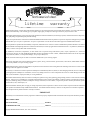
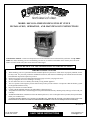
NorthAmerica’sBest
MODEL 800 NOVA FREESTANDING PELLET STOVE
INSTALLATION, OPERATION, AND MAINTENANCE INSTRUCTIONS
CONGRATULATIONS—You are now the proud owner of one of the finest stoves in the world for your home—the QUADRAFIRE! Now before installing your stove and building your first fire, record the serial number on the warranty card. The serial
number is located on the safety label on the back wall of the hopper.
PLEASE READ ALL OF THE OWNERS MANUAL AND SAFETY NOTES
IMPORTANT SAFETY NOTES
1.
2.
3.
4.
5.
6.
7.
8.
9.
When installing your stove, particular attention should be paid to fire protection. If this unit is not properly installed, a house
fire may result. For your safety, follow the installation instructions, and contact local building or fire officials about restrictions
and installation inspection required in your area.
Read power supply section of component information (page 16) before you plug in the stove.
Always unplug the stove before cleaning or servicing.
Do not connect the stove to a chimney flue already serving another appliance.
The stove operates with a negative pressure firebox and a positive pressure exhaust. It is imperative that the chimney system
be airtight and installed correctly.
Dispose of all ashes in a metal container.
Comply with all minimum clearances to combustibles as shown on page 5.
The Quadra-Fire 800 NOVA is tested and approved for pelleted biomass fuel only. Burning of any other type of fuel voids your
warranty!
Aladdin Hearth Products, manufacturer of the 800 NOVA pellet stove, reserves the right to alter its products, their specifications
and/or price without notice.
ALADDIN HEARTH PRODUCTS, GRANTS NO WARRANTY, IMPLIED OR STATED, FOR THE INSTALLATION OR
MAINTENANCE OF THIS UNIT AND ASSUMES NO RESPONSIBILITY FOR ANY CONSEQUENTIAL DAMAGE(S).
Revised 3/98
Part #250-2230 #812-2520
401 N. Wynne Street
Colville, WA 99114
SAVE THESE INSTRUCTIONS
www.quadrafire.com
[email protected]
NOTES
Page 2
TABLE OF CONTENTS
Page
Safety Label .............................................................................................................................................................. 4
Listing and Specifications ........................................................................................................................................ 5
Installation ................................................................................................................................................................ 5
Clearances to Combustibles ..................................................................................................................................... 5
Chimney and Exhaust Connections .......................................................................................................................... 5
Floor Protection ........................................................................................................................................................ 6
Venting Termination Requirements .......................................................................................................................... 6
Venting Systems ....................................................................................................................................................... 7
A. Alcove .......................................................................................................................................................... 7
B. Through The Wall ........................................................................................................................................ 7
C. Vertical ......................................................................................................................................................... 8
D. Through The Wall And Vertical ................................................................................................................... 8
E. Masonry ....................................................................................................................................................... 8
F. Alternate Masonry ........................................................................................................................................ 8
Venting Graph ........................................................................................................................................................... 9
Top Vent Flue Adapter and Feed Adjustment Instructions ...................................................................................... 10
Mobile Home Installation ......................................................................................................................................... 11
Thermostat Installation ............................................................................................................................................. 11
Operating Instructions .............................................................................................................................................. 12
Schematic ................................................................................................................................................................. 13
Schematic Key and Electrical Schematic ................................................................................................................. 14
Cleaning and Maintenance ....................................................................................................................................... 15
Component Information ........................................................................................................................................... 16
Troubleshooting ........................................................................................................................................................ 18
Warranty ................................................................................................................................................................... 20
Warranty Card........................................................................................................................................................... Insert
Page 3
SAFETY LABEL
(FOUND ON BACK WALL OF HOPPER)
Page 4
LISTINGS AND SPECIFICATIONS
QUADRA-FIRE 800 NOVA pellet stoves are safety tested and listed with Warnock Hersey International to ASTME 1509 and ULCS627.
Also suitable for mobile home installation (see page 11 for details).
HEAT INPUT*:
PARTICULATE EMISSIONS PER HOUR:
DIMENSIONS:
28,000 to 37,500 BTU per hour
0.9 grams per hour
WIDTH-261/2" (673mm), DEPTH-24” (609mm), HEIGHT-291/2" (749mm)
*BTU INPUT WILL VARY, DEPENDING ON THE BRAND OF FUEL YOU USE IN YOUR STOVE.
CONSULT YOUR QUADRA-FIRE DEALER FOR BEST RESULTS.
INSTALLATION
CLEARANCES TO COMBUSTIBLES
Minimum Clearances To Combustible Material (USA in inches, Canada in mm).
RESIDENTIAL/MOBILE HOME
HOME
A = 8” (150mm)
B = 2” (50mm)
Horizontal Installation
RESIDENTIAL/MOBILE HOME
RESIDENTIAL/MOBILE HOME
A = 8” (150mm)
C = 3” (75mm)
Vertical Installation
with 6” (152mm) Top Vent Kit
F = 2” (50mm)
Horizontal and Vertical
Comer Installation
RESIDENTIAL/MOBILE
C = 3” (75mm) D = 8” (200mm)
(from side of the stove face)
E = 2” (50mm)
CLEARANCES TO COMBUSTIBLES (USA IN INCHES, CANADA IN MM)
Back:
Side:
Corner:
From side of stove face:
Top Vent
Kit With
3” Pipe
8” (200mm)
2” (50mm)
2” (50mm)
8” (200mm)
Rear
Vent
2” (50mm)
2” (50mm)
2” (50mm)
8” (200mm)
Top Vent
Kit With
6” Pipe
9” (225mm)
2” (50mm)
2” (50mm)
8” (200mm)
CHIMNEY AND EXHAUST CONNECTION
1.
2.
3.
4.
CHIMNEY & CONNECTOR: Use 3” (76mm) or 4” (102mm) diameter type “L” or ”PL” venting system.
MOBILE HOME: Approved for all listed pellet vent. If using the 3" (76mm) or 6" (152mm) vertical top vent kit, you must use either
listed double wall flue connector to Class A pipe, or all Class A pipe. Mobile home venting system must be equipped with a spark
arrestor and rain cap.
RESIDENTIAL: The 3" (76mm) and 6" (1 52mm) vertical top vent kits are tested to use 24 gauge single wall flue connector or listed
double wall flue connector to Class A listed metal chimneys or masonry chimneys meeting ICBO standards for solid fuel appliances.
The stove is approved for all 3" (76 mm) or 4" (102 mm) diameter listed pellet vent. It can be either vertically or horizontally vented.
NOTE: All pipe must be sealed using welded seam pipe whenever possible. Seal pipe joints with high temperature silicone (500°F
[260°C] minimum rated only).
Page 5
FLOOR PROTECTION
MINIMUM CLEARANCES TO COMBUSTIBLE MATERIALS
The floor protector must be noncombustible material, extending beneath heater and to the front, sides, and rear as indicated
below.
G = 2" (50mm)
H = 6" (150mm)
NOTE: In a corner installation, the floor protection must follow the above clearances.
VENTING TERMINATION REQUIREMENTS
1.
Do not terminate vent in any enclosed or semi-enclosed area such as a carport, garage, attic, crawl space, under a sun
deck or porch, narrow walkway or closely fenced area, or any location that can build up a concentration of fumes such
as a stairwell, covered breezeway, etc.
2.
Vent surfaces can get hot enough to cause burns if touched. Noncombustible shielding or guards may be required.
3.
Termination must exhaust above air inlet elevation. It is recommended that at least 5’of vertical pipe be installed when
appliance is vented directly through a wall to create natural draft, which will prevent the possibility of smoke or odor
during appliance shutdown, and to keep exhaust from causing a nuisance or hazard by exposing people or shrubs to high
temperatures. In any case, the safest and preferred venting method is to extend the vent vertically through the roof.
4.
Distance from doors and windows, or gravity or ventilation air inlet into building:
a. Not less than 4' (1.2m) below;
b. Not less than 4'(1.2m) horizontally from;
c. Not less than l’ (305mm) above.
5.
Distance from bottom of termination and grade - 12" (305mm) minimum. This is conditional upon plants and nature of
grade surface. The grade surface must be a noncombustible material (i.e., rock, dirt). Distance from bottom of termination
and public walkway - 7' (2.1 m) minimum.
6.
Distance to combustible materials - 2' (510mm) minimum. This includes adjacent buildings, fences, protruding parts of
the structure, roof overhang, plants and shrubs, etc.
Page 6
Page 7
Page 8
Page 9
TOP VENT FLUE ADAPTER INSTALLATION INSTRUCTIONS
3"-3" ADAPTER
3"-6" COLLAR
1)
2)
3)
4)
5)
6)
7)
8)
9)
#811-0450
#812-2690
Put a layer of silicone on the 3" (76mm) exhaust outlet.
Slide the flue adapter onto the rear exhaust outlet.
Adjust the assembly to a vertical position.
Slide the outer shield up or down to mate evenly with the top of
stove.
Tighten the adjusting screws (A) when the shield is in the proper
position.
Drill two hole (B) with #26 drill bit (provided) into the back of the
stove using the outer shield as a pattern (make sure the assembly
is vertical).
Insert the mounting gaskets between the stove and the outer
shield.
Install the four mounting screws (B).
Install the stove pipe into the adapter (be sure to silicone all
joints).
FEED ADJUSTMENT INSTRUCTIONS
1)
2)
3)
4)
5)
Remove any fuel in the hopper.
Loosen set screw.
Loosen wing nut.
Adjust the fuel feed forward to increase the feed, toward the back of the stove to decrease the feed.
Tighten the set screw and the wing nut.
NOTE: Adjust fuel after the stove has been burning for 10 to 15 minutes. The flames should be 4" to 6" (I 02mm to 152mm) above
the firepot after adjustment.
Page 10
MOBILE HOME INSTALLATION
OUTSIDE AIR KIT FOR 800 NOVA: PART #811-0420 (FLOOR) OR PART #811-0430 (REAR)
1
2.
3.
4.
5.
6.
7.
An outside air inlet must be provided for the combustion air and be unrestricted while the stove is in use.
The stove must be secured to the mobile home by bolting it to the floor (using lag bolts).
Do not install the stove in a sleeping room.
The structural integrity of the mobile home floor, walls and ceiling/roof must be maintained (i.e., do not cut through floor
joists, wall studs, ceiling trusses, etc.).
The stove must be grounded with #8 copper grounding wire or equivalent, terminated at each end with an NEC approved
grounding device.
Refer to clearances to combustibles section on page 5 for listings to combustibles and appropriate chimney systems.
Seal all wall or floor inlets to prevent air or moisture penetration. Check periodically to ensure the inlet is f ree of
obstruction (e.g., snow, ice).
THERMOSTAT INSTALLATION
1.
2.
3.
A 24 volt AC thermostat is required to operate this pellet stove. Some thermostats are equipped with an adjustable heat
anticipator. Our current rating is .05 amps. The anticipator needs to be adjusted to the lowest setting available.
When mounting a thermostat on a wall, be sure to follow your thermostat installation instructions carefully.
NOTE: Be sure the thermostat is mounted level for accurate readings. The thermostat should be mounted
on an inside wall and not in direct line with the stove convection air.
NOTE: If the thermostat is located too close to the stove, you may need to set the temperature setting
slightly higher to maintain the desired temperature in your home.
There is a four screw terminal block located on the back of the stove beside the fuse receptacle, adjacent to the power
cord inlet. The top and bottom screws are the mounting screws for the terminal block. The center two screws are for
the thermostat wires. Attach the red wire to the second screw from the top on the terminal block and the white wire to
the third screw from the top.
Page 11
OPERATING INSTRUCTIONS
1. FUEL SIZE AND MATERIAL
Fuel pellets are made from sawdust or wood byproducts. If the source material is hardwood, they will have a higher mineral
content, creating a heavier ash. Minerals and other noncombustible materials, such as sand, will turn into glass when heated
to the extreme temperatures our firepot reaches. This is what forms clinkers in the bottom of the firepot. Trees from
different areas will vary in mineral content. That is why some fuels produce more clinkers than others. Pellets are manufactured
in either 1/4" (6mm) or 5/16" (8mm) diameter and many varying lengths. Pellet lengths may even vary by lot from the same
manufacturer, which is why the feed rate may need to be adjusted occasionally. We recommend that you buy fuel in multiton lots whenever possible. Buying large quantities of fuel at once will greatly reduce the number of times the feed adjustments
will need to be made. However, we do recommend trying various brands before purchasing multi-ton lots to ensure customer
satisfaction.
NOTE: This stove will operate properly with either 1/4” (6mm) or 5/16” (8mm) diameter pellets. However,
pellets exceeding 1 1/4” (32mm) in length can cause missed ignitions.
2. BEFORE YOUR FIRST FIRE.
a. First, make sure your stove has been property installed and that all safety requirements have been met. Pay particular
attention to the fire protection, venting and thermostat installation instructions.
b. Now open the front door of the stove and remove all of the accessories that were placed there for shipment. Remove all
labels that are affixed to the glass.
c. Check the position of the thermocouple and make sure that it protrudes approximately 1" (25mm) into the firepot. It may
be necessary to slide the thermocouple and protection tube into their proper positions. Now close the front door.
NOTE: Thermocouple cover tip must be touching thermocouple tip.
d. You are now ready to load fuel, but first see that all accessories have been removed from the hopper. Now fill the hopper
with pellets.
e. Remember that a working thermostat is required for proper operation of this stove. At this time, set the thermostat to its
lowest setting.
3. START YOUR FIRST FIRE
a. Now plug the stove in. The combustion blower will come on. Even though the thermostat is not calling for heat, the
combustion blower will stay on for approximately 10 minutes. This is normal.
b. Next, adjust the themostat to its highest setting. The red light next to the restart button on the left side of the stove will
come on. This will indicate that the thermostat is calling for heat.
c. The fuel feed system and the igniter are now turned on.
d. For your first fire, it will be necessary to press the restart button once at approximately two and a half minutes for start up,
and again at five minutes. This will fill the feed system and allow the stove to light.
e. The stove will now continue to run as long as the thermostat is calling for heat. Once the stove has ignited, let the stove
bum for approximately 15 minutes, then set the thermostat to the desired room temperature.
4. GENERAL OPERATION INFORMATION
a. Understand that the stove is like most modern furnaces in that it has only one burn rate, full on. When the thermostat calls
for heat, your stove will automatically light and deliver heat in the most efficient and economical way.
b. Once all of the start-up procedures have been completed, simply set the thermostat to a comfortable setting and enjoy the
stove. But remember, you will have to add pellets. The thermostat’s location will have some effect on the stove’s
operation. When the thermostat is located close to the stove, it may require a slightly higher temperature setting to keep the
rest of the house comfortable. If the thermostat location is upstairs while the stove is downstairs, you will notice higher
temperatures near the stove.
c. During each ignition cycle, it is normal to see some smoke. The smoke will stop once the fire starts.
d. After your stove has been burning for approximately 15 minutes, the convection blower will automatically turn on. This
blower transfers heat from your stove into the room, and will continue to run after the thermostat has stopped calling for
heat until all of the heat has been extracted from the stove.
e. Occasionally, the stove may run out of fuel and shut itself down. If this happens, the red light will be on. To restart the
stove, fill the hopper and press the restart button next to the light. When you press the restart button the red light will go out,
and when the button is released the light will come back on. You should see a fire in about four minutes. If not, press the
restart button again.
Page 12
Page 13
(N) COMBUSTION BLOWER (WHITE)
Page 14
CLEANING AND MAINTENANCE
NOTE: Unplug the stove before performing any cleaning or maintenance
1. FIREPOT
A. It takes very little time to clean the firepot. We recommend that you clean the firepot at least once a week. However, if the fuel you
are burning has a high dirt content, it will be necessary to clean the firepot more often. Dirty fuel will cause clinkers to form in the
firepot. A clinker is formed when dirt or a nonburnable substance is heated to 2000°F (1093°C) and becomes glass-like.
B. To clean the firepot:
1. Wait for stove to be in complete shutdown (exhaust blower off).
2. Pull firepot cleanout rod out, then ride back into the closed position.
3. Open front pedestal access door and empty ash tray.
NOTE: Do not allow cleanout rod to slam back into closed position. This may damage igniter.
NOTE: NEVER pull rod when stove is operating.
2. FIREBOX ASH REMOVAL
A. Clean as needed. When the stove is cool, remove ash and place it in a metal or noncombustible container. Place the container in
a safe area, away from combustible materials.
NOTE: Embers remain hot for many days. Store in a safe place away from combustibles.
3. HEAT EXCHANGER MAINTENANCE AND CLEANING
A. This stove has two heat exchange chambers. Each chamber is equipped with its own cleaning rod. To access the cleaning rods,
simply lift the stove top up by the front approximately 5" (127mm) and secure the lid open with the support rod located on the right
side (the stove top is hinged at the rear). Make sure the support rod drops into the receiver located directly under it on the far right
side. Be sure the lid is properly secured before continuing. The end of each cleaning rod is located next to the face of the stove.
Both rods are equipped with a receiver for the cleaning handle. To clean the heat exchangers, insert the cleaning handle into the
receiver and pull straight out approximately 20" (508mm). Move the rod in and out a couple of times. After cleaning both heat
exchangers, lift the stove top approximately 1" (25mm) and then slowly lower it back into position.
B. HOW OFTEN SHOULD YOU CLEAN THE HEAT EXCHANGER? The amount of ash buildup in the firepot will be a good guide
to determine how often you should clean the heat exchanger. Every time you clean the firepot, clean the heat exchangers. This will
keep your stove running at peak efficiency. Also, after burning approximately one ton of fuel, the ash will need to be removed from
beneath the heat exchangers. To do this, remove the left side panel of the stove by loosening the four attachment screws. Pull out
on the bottom of the panel and slide down from the two upper screws. Open the exhaust cleanout door with the T-handle provided
and vacuum out the exhaust chamber. Then reinstall the exhaust door and side panel.
4. VENTING SYSTEM
The venting system should be inspected and cleaned at least once a year, or more often depending upon the quality of your fuel. If
you are experiencing nuisance shutdowns, check for a clogged exhaust system. If the exhaust is restricted, the vacuum safety switch
will shut the feed motor off (the red light will remain on).
5. DOOR HANDLE ADJUSTMENT
The door latch is adjusted by removing the nut on the back of the door latch. Remove the latch cam and square key, and add or subtract
a washer to space the cam as needed.
6. BLOWERS
A. There are two blowers in this stove: an exhaust blower that vacuates the exhaust out of the firebox, and a convection blower that
delivers heat into the room. THESE BLOWERS REQUIRE NO LUBRICATION.
B. The exhaust blower is located on the right side of the stove. To inspect it, remove the right rear pedestal access door.
NOTE: There is no need for annual cleaning.
C. The convection blower is accessible by removing the left rear pedestal access door. The impeller on this blower should be cleaned
at least once a year. You can do this without removing the blower. Simply brush and vacuum the impeller area.
7. READING THE FIRE AND ADJUSTMENT PROCEDURES
A properly adjusted fire has a short active flame pattern that extends out of the firepot 4" to 6" (102mm to 152mm). If the fire has tall
flames with black tails and seems somewhat lazy, the feed rate will need to be reduced. This is done by sliding the feed adjustment plate
down, which will reduce the feed. If the fire is not 4" to 6" (102mm to 152mm), slide feed plate up to increase the feed. Allow five
minutes for feed adjustment to take effect.
Page 15
COMPONENT INFORMATION
1. POWER SUPPLY
6. JUNCTION BOX AND WIRING HARNESS
A. Check the wall receptacle for 120 volt, 60 Hz (standard
current). Make sure the outlet is grounded and has
the correct polarity.
A. The junction box and the wiring harness are located
on the left side of the stove. They are part of a
three piece set. The lower junction box contains
both the capacitors, the thermocouple terminal block
and the computer card receptacle for the control
box. The upper junction box contains the red call
light, the reset button, the thermostat terminal block,
the 7 amp fuse, and the power receptacle. The wiring
harness connects the upper and the lower junction
boxes and also disperses connections to the other
electrical components.
B. The junction box and the wiring harness are replaced
as one component.
2. FUSE
A. The fuse is located on the left side, next to the restart
button and the indicator light. However, to access
the fuse, you must remove the left side panel. To
inspect the fuse, push the fuse holder in and turn the
holder cap counterclockwise, then pull out. Replace
with a standard 7 amp 120 volt fuse, if necessary. If
the fuse continues to blow, contact your local dealer.
3. RED CALL LIGHT
A. The red call light is located on the left side next to the
reset button. The function of the red call light is to
indicate that the thermostat is calling for heat.
B. If the thermostat is calling for heat, the stove is
burning, and the light is not on, check the bulb.
Replace with a 28 volt AC (#85 lamp) bulb.
7. THERMOSTAT
A. The stove is designed to run on a 24 volt AC
thermostat. Remove the front cover and check to
see that the contact points are not stuck in either the
open or closed position, and that both wires are
property connected to the thermostat.
NOTE: The anticipator should be set on the
lowest setting available. Also, check the wire
leads at the terminal block located at the back
of the stove for loose connections.
4. RESET BUTTON
A. The reset button is located on the left side of the
stove, next to the red call light. The function of the
button is to momentarily open the thermostat circuit,
which restarts the system. However, this will only
work when the thermostat is calling for heat and the
red light is on.
B. If the light is on, there is no fire, and there is fuel in
the firepot, push the reset button and wait for ignition.
You should have a fire within five minutes.
C. If the light does not go out when the reset button is
pushed, the reset button switch may be faulty.
Contact your local dealer.
8. CONTROL BOX
5. VACUUM SWITCH
A. The vacuum switch is located on the left side of the
stove, just above the red call light and the reset button.
This switch turns the feed system on when vacuum
is present in the firebox. Check the rubber hose for
leaks or cracks if the feed system fails to start. Also,
be sure there is no restriction in the exhaust system
and the exhaust blower is running. The vacuum
switch is a safety device to shut off the feed motor
under the conditions above.
B. If the exhaust or the heat exchanger system is dirty
or plugged, the vacuum switch will keep the feed
system from starting.
C. If the firebox door is open, the vacuum switch will
keep the feed system from starting.
Page 16
A. The control box is located on the lower left side of
the stove. It is plugged into the junction box. If the
stove has just been plugged in and the combustion
blower does not start, check the control box to see
that it is securely plugged in. If this does not solve
the problem, consult your local dealer.
B. The green light located on the front of the control
box notifies you that the stove has reached a
temperature of 200°F (93°C) in the firepot. If this
light is not lit in the first four minutes of operation,
the stove will shut down. Check the thermocouple.
C. The red light located to the left of the green light is to
indicate that the stove has reached operating
temperature. If this light does not come on in the
first nine minutes of startup, the stove will shut down.
The stove will not try to relight again by itself. You
must manually push the reset button to restart the
cycle.
D. If you suspect a problem with the control box,
disconnect the power supply from the stove, then
remove the control box and take it to your nearest
Quadra-Fire dealer for testing.
NOTE: Do not open the control box. This will
void the warranty. Do not plug in or remove
control box without first unplugging the stove.
9. THERMOCOUPLE
A. The thermocouple is located on top of the firepot inside the
ceramic protection tube. Remove the ceramic tube and
inspect the thermocouple for deterioration or breakage.
B. Check the terminal block screws to see if they are tight and
making a good electrical connection (located on the top of
the lower junction box).
NOTE: The yellow wire is connected to the terminal located
closest to the front of the stove. The red wire is connected
to the terminal closest to the rear of the stove.
C. Upon reinstalling the ceramic cover, be sure the thermocouple
is touching the inside end of the ceramic tube and that the
cover is extending 1” (25mm) into the firepot.
D. The thermocouple sends a millivolt signal to the control box
to obtain the green and red lights for the preset
temperatures.
10. SNAP DISC #1 (CONVECTION BLOWER) - 125°F
A. Snap disc #1 is located on the bottom of the heat
exchanger next to the convection blower. This snap disc
turns the convection blower (heated air) on and off as
needed. Power is always present at snap disc #1.
°F
11. SNAP DISC #2 (THERMOSTAT OVERRIDE) -250°
A. Snap disc #2 is located next to snap disc #1, farthest from
the convection blower. This snap disc will bypass the
thermostat and turn off the stove if an overheat condition
occurs, or if the convection blower should fail to operate.
The stove will go into a normal shutdown: the combustion
blower will run for ten minutes, then turn off . After the
stove cools, the snap disc will automatically reset itself and
the stove will relight.
°F
12. SNAP DISC #3 (BACKBURN PROTECTOR) - 200°
A. Snap disc #3 is located on the right side of the feed tube
(accessed through stove top). If, for any reason, the fire
tries to burn back into the feed system or push exhaust up
the feed tube, this snap disc will shut the entire system off.
However, sometimes in shipment the disc will trip and shut
power off to the entire stove. To reset, unplug the stove
from outlet and push in the red reset button in the center of
the snap disc, then plug the stove back in and try to relight
it.
13. BLOWER #1 (EXHAUST BLOWER)
A. The 80 cfm exhaust blower is located on the lower right
side of the stove. The exhaust blower is designed to pull
the exhaust from the stove and push it out through the
venting system. To inspect it, remove the right rear
(facing the stove from the front) pedestal access door.
The blower may now be visually inspected.
B. This blower requires a 3 uf capacitor for operation.
14. BLOWER #2 (CONVECTION BLOWER)
A. The 80 cfm convection blower is located on the lower left
side of the stove. The convection blower blows heated
air through the heat exchange system into the room.
B. The blower is accessible by removing the left rear (facing
the stove from the front) pedestal access door. You
should inspect this blower at least once a year. If dust
buildup has accumulated, clean by simply brushing and
vacuuming dust off the blades.
C. This blower requires a 4 uf capacitor for operation.
15. CAPACITORS
A. The 3 and 4 uf capacitors are located in the lower left side
of the stove. They are seated in the lower junction box.
16. FEED SYSTEM
A. The feed system is located beneath the top of the stove and
centered in front of the hopper. Lift the hopper lid to access.
This system pulls pellets, by using a hollow auger spring,
up the feed tube from the hopper area and drops them down
the feed chute into the firepot. If you are having fuel
problems check the following:
1. Check the ramp in the firepot to see that it is free of fuel
or other materials.
2. Check the set screw on the end of the motor shaft to see
that it is tight and not slipping.
3. Check the electrical power to motor.
4. Check the vacuum switch hose connections.
17. IGNITER
A. The igniter is located in the chamber at the bottom of the
firepot.
NOTE: The element on the igniter is extremely brittle. Be
very careful in handling it.
B. Check the wire leads to the igniter for loose or bad
connections (ceramic wire nuts).
NOTE: Unplug stove before checking wire nuts.
18. FIREPOT
A. Clean the firepot (see section on cleaning and
maintenance on page 15).
B. Make sure the cleanout plate in the bottom of the firepot is
pushed in all the way.
C. Check the gasket between the firepot and the firebox bottom.
A bad seal will affect the ignition time and the flame height.
19. DOOR GASKET
A. Check the door gasket to see that the door is completely
closed and there are no air leaks. This can be done by
closing the door on a piece of paper and checking that the
paper is firmly held in place. You should have resistance
when you try to pull the paper away.
NOTE: If no resistance is found, the door handle assembly
needs to be adjusted or rope seal needs to be replaced.
20. HEAT EXCHANGERS
A. The heat exchangers (one on each side) can be accessed by
lifting the stove top. Each heat exchanger has a cleanout
rod located in the center of the heat exchanger. To clean
heat exchanger see page 15, heat exchanger cleaning and
maintenance.
Page 17
TROUBLESHOOTING
NOTE: In order to identify the component location, refer to schematics on pages 13 and 14.
CAUTION: UNPLUG STOVE BEFORE SERVICING
1. PLUG IN STOVE, NO RESPONSE
A. Check the power supply for 120 volts AC.
B. Check the fuse in the junction box (7 amp, 120 volt fuse
AGC-7).
C. Check snap disc #3 (unplug stove before checking). Push
reset on snap disc #3.
D. Control box (consult your dealer).
2. CALL LIGHT ON, NO FIRE, NO FUEL IN FIREPOT
A. Check the hopper for fuel, sawdust or bridging of pellets
in the bottom of the hopper. If the hopper is low on fuel,
vacuum can be lost through the hopper.
NOTE: Sometimes there might still be fuel in the
hopper. If so, continue to check the areas below.
B. Make sure that the exhaust blower is operating.
C. Check the venting system for obstructions that might
cause restrictions, which would cause the vacuum safety
switch to shut off the auger.
D. Check the heat exchanger system for high ash content. If
buildup is present, clean the heat exchanger system.
E. Push the reset button, and try, to light the stove again.
3. CALL LIGHT ON, NO FIRE, PARTIALLY-BURNED
FUEL IN THE FIREPOT
A. Clean the firepot. Check that the igniter hole is clean and
the cleanout plate is tightly in place.
B. Inspect the thermocouple and cover for the following:
1. The cover needs to be making contact with the end of
the thermocouple.
2. The thermocouple and the cover should extend
approximately 1” (25mm) into the firepot (for
accurate temperature reading).
3. Push the restart button. When the thermocouple
reaches 200°F (93°C) the GREEN LIGHT will come
on, and at 1000°F (538°C) the RED LIGHT will
come on.
NOTE: If the lights fail to come on after the fire
starts, the thermocouple may be faulty.
C. If the thermocouple appears good, the control box may be
the problem (consult your dealer).
4. CALL LIGHT ON, NO FIRE, UNBURNED PELLETS IN
FIREPOT
A. Clean the firepot.
B. Push the reset button.
C. Check the igniter to see that it comes on. If it does not turn
on, check the following:
1. Check the connections under the firepot. (Ceramic wire
nuts must be used to withstand the heat produced by
the firepot.)
2. Make sure that the igniter is property installed in the
igniter bracket. It should fit tightly, and be centered in
the igniter hole.
5. SLOW OR SMOKY START-UP
A. Clean the firepot. Check the firepot gasket for a good
seal between the firepot and the firebox floor.
B. Check the combustion blower (make sure that it is
starting when the thermostat calls for heat).
C. Visually check the cleanliness of the firebox, the heat
exchangers and the venting system.
D. The feed rate may be too high. If necessary, adjust with
the fuel adjustment rod located in the hopper.
E. Due to elevation, the air adjusting plate (located on the
left side in the cleanout area of the pedestal) may need to
be adjusted to get the right air to fuel ratio.
6. STOVE RUNS FOR 10 MINUTES, THEN STOPS
FEEDING FUEL
A. Inspect the thermocouple and the cover.
1. The cover needs to make contact with the end of the
thermocouple.
2. The thermocouple and the cover should extend
approximately 1 n (25mm) into the firepot.
3. Push the reset button. The thermocouple test lights
located on the control box will automatically turn on;
when the thermocouple reaches 200°F (93°C) the
GREEN LIGHT comes on, and at 1000°F (538°C)
the RED LIGHT comes on. If they fail to turn on
after the fire starts, the thermocouple may need
replacement.
4. Check the control box (consult dealer).
7. FEED SYSTEM FAILS TO START
A. Make sure that the front door to the firebox and the door to
the ash cleanout in the pedestal are closed tightly.
B. Check to make sure that the exhaust blower is coming on
and working.
C. Check the heat exchangers and the venting system for
obstructions or heavy ash buildup.
D. The vacuum switch hose may be plugged.
1. Pull the hose off and blow through it to make sure it is
clear.
NOTE: Unplug stove from power outlet first.
E. Downdrafts or poor venting systems that do not follow
manufacturers recommendations can also cause this
problem.
F. Check the hopper and the feed system for blockage.
Page 18
8. THERMOSTAT WILL NOT START UNIT
A. Check the power to the stove.
1. Unplug for 10 seconds and then plug in. The
exhaust blower should come on. If it does, go
to B.
B. The thermostat or the thermostat wiring maybe
faulty.
1. Disconnect the thermostat wires from the
terminal block located on the back of the stove.
Make a jumper wire in order to create a manual
bypass to determine if the stove or the
thermostat is faulty.
NOTE: Unplug the stove while hooking up
the jumper wire. Plug the stove back in and
the unit should come back on and light. If
the unit lights, check the thermostat and the
wires connecting them.
C. Snap disc #2 would bypass the thermostat if an
overheat situation occurs. The snap disc should reset
itself once it cools down.
D. Snap disc #3 may need to be manually reset if the unit
has overheated.
E. Check the control box (consult dealer).
9. UNIT FAILS TO SHUT OFF
A. Check the thermostat and the thermostat wires.
1. Remove one of the thermostat wires from the
terminal block; the stove should go into a
normal shutdown cycle.
B. Check the control box (consult dealer).
C. Check the junction box (consult dealer).
10. SMOKE FROM THE CONVECTION AIR
OUTLET
A. Check the exhaust blower housing and all venting
connections.
B. Most problems with smoke-in-the-house are the result
of a poor venting system.
11. CONVECTION BLOWER KEEPS RUNNING OR
FAILS TO START
A. Snap disc #1 may need to be replaced.
B. Check the wire connections on snap disc #1 and the
convection fan to be sure a good contact is being
made.
C. Check the convection blower and capacitor (consult
dealer).
12. STOVE CYCLES ON AND OFF, THERMOSTAT
ALWAYS ON
A. Check that snap disc #1 is coming on and turning
the convection blower on. If not, snap disc #2
could be bypassing the thermostat until the snap
disc cools and resets itself.
13. LARGE FIRE, ASH BUILDUP AND DIRTY
GLASS
A. Clean the firepot. Check the firepot gasket for a good
seal between the firepot and firebox surfaces.
B. Visually check the cleanliness of the firebox, the heat
exchangers and venting system.
C. Reduce the feed rate, if necessary, to maintain a fire
height of about 4" to 6" (102mm to 153mm) above
the top of the firepot.
D. If all the above do not help, an air adjustment may be
needed. The air adjustment plate is located in the
ash cleanout in the pedestal. Open more to increase
air to help even the air to fuel ratio.
14. UNIT BURNING, NO CALL LIGHT
A. Replace light bulb (#85 lamp).
15. STOVE IGNITES THEN GOES OUT, LIGHTS
STILL ON = NUISANCE SHUTDOWN
A. Inspect the thermocouple and the cover.
1. Make sure that the thermocouple end and the
cover make contact.
2. The thermocouple and the cover should extend
approximately 1” (25mm) into the firepot.
3. Push the reset button. When the thermocouple
reaches 200°F (93°C) the GREEN LIGHT will
come on, and at 1000° F (538°C) the RED
LIGHT will come on.
B. Check the fire height. It should be 4” to 6" (102mm
to 153mm) out of the firepot.
1. Too high of a fire will lower vacuum in the
firebox and the vacuum switch may turn off the
feed system, resulting in total shutdown or feed
system shutdown until vacuum is regained.
NOTE: This may also happen in
complicated venting systems, or at high
altitudes. Use the feed adjustment plate to
slow fuel input and reduce flame height. If
this does not help, check the air adjustment
plate.
2. Too low of a fire will let the firepot temperature
drop below 1000°F (538°C) and will turn the
stove off. Increase fuel, check for sawdust and
bridging of pellets.
C. Check the heat exchanger and the venting system
for buildup or restriction (cleanout ash buildup).
D. Check the vacuum switch for proper operation.
1. Make sure that the vacuum hose is not clogged.
2. With normal operation, the vacuum switch
should shut the feed system off when the door is
opened, and restart the feed system when the
door is closed again.
Page 19
NorthAmerica’sBest
lifetime
warranty
Aladdin Hearth Products, warrants their pellet heating appliances to the original purchaser for the lifetime of the appliance, to be free from defects in
material and workmanship. This warranty gives you specific legal rights; you may have other rights which may vary from state to state.
This limited Lifetime Warranty covers items such as but not limited to combustion chambers, heat exchanger systems, stainless steel firebox components,
doors, gold plating, and glass damaged by thermal breakage.
All parts to be replaced must be returned to an authorized Aladdin Hearth Products dealer at purchaser’s expense for inspection and approval by Aladdin
Hearth Products prior to repair or replacement. No repair or replacement costs will be honored without approval of Aladdin Hearth Products.
This new Quadra-Fire product must be installed by a competent, authorized service contractor. It must be installed and operated at all times in accordance
with the Installation and Operating Instructions contained in this manual, as well as any applicable local and national codes. Any alteration, willful abuse,
accident, or misuse of the product shall void this warranty.
Any installation, construction, transportation, or other related costs or expenses arising from defective part(s), repair, replacement, etc., will not be
covered by this warranty, nor will Aladdin Hearth Products assume responsibility for them. Further, Aladdin Hearth Products will not be responsible
for any incidental, indirect, or consequential damages, except as provided by law.
Our EZ Clean and ceramic firepots are both covered under Aladdin’s three year warranty program.
All electrical components such as but not limited to blowers, igniters, wiring, vacuum switches, speed controls, control boxes, and thermodisc switches
are covered by Aladdin’s one year warranty program.
Aladdin Hearth Products, will not be responsible for any alteration to the unit which causes sooting that results in damage to the interior or exterior of the
building in which this appliance is installed.
This warranty is void if the stove has been operated in atmospheres contaminated by chlorine, fluorine, or other damaging chemicals, the stove is subjected
to prolonged periods of dampness or condensation, or there is any damage to the stove or other components due to water or weather damage which is the
result of, but not limited to, improper chimney or venting installation.
This limited Lifetime Warranty does not extend to or include paint, pellet stove logs, door gasketing, glass gasketing, firebrick or other ceramic insulating
materials. It does not cover installation or operational-related problems such as overfiring, downdrafts or spillage caused by environmental conditions,
nearby trees, buildings, hilltops, mountains, inadequate venting or ventilation, excessive offsets, or negative air pressures caused by mechanical systems
such as furnaces, fans, clothes dryers, etc.
This limited Lifetime Warranty does not apply to venting components, hearth components or other accessories used in conjunction with the installation
of this product not manufactured by Aladdin Hearth Products. This limited Lifetime Warranty is effective on all pellet stoves sold after September 1,
1996, and supersedes any and all warranties currently in existence.
IMPORTANT
This warranty is not valid unless the warranty registration card has been property completed in full and returned within 10 days from the date of purchase.
FOR YOUR RECORDS:
DATE PURCHASED _________________________________________ MODEL # _________________________________________________
AUTHORIZED DEALER ______________________________________ SERIAL # __________________________________________________
Copyright Aladdin Hearth Products, June 1997 (250-2230)