1
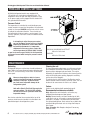
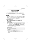
®
Shelleyglas /Shelleysteel™
Service and Installation Manual
Please read this manual completely before attempting to install or operate this equipment!
Notify carrier of damage! Inspect all components immediately. See page 2.
Refrigerated, Heated and Non-Electrical Units
N
CAUTIO
TION
A
M
R
O
T INF
N
A
T
R
O
IMP
RE USE
O
F
E
B
ONS!
I
T
C
READ
U
R
INST
E
S
E
H
T
AVE
S
E
S
A
E
PL
Effective March 2003
Shelleyglas®/Shelleysteel™ Service and Installation Manual
CONTENTS
RECEIVING & INSPECTING EQUIPMENT ................................. 2
SPECIFICATIONS........................................................................ 3
INSTALLATION .......................................................................... 4
OPERATION.............................................................................4-5
MAINTENANCE .......................................................................... 6
CLEANING LIQUITEC ................................................................. 7
FOOD WELL ASSEMBLY............................................................ 7
WIRING DIAGRAM .................................................................8-9
STANDARD LABOR GUIDELINES............................................ 10
REPLACEMENT PARTS LIST................................................... 11
STANDARD WARRANTY.......................................................... 11
PARTS DEPOTS ........................................................BACK PAGE
©2003 The Delfield Company. All rights reserved. Reproduction without
written permission is prohibited.
“Delfield” is a registered trademarks of The Delfield Company.
SERIAL NUMBER INFORMATION
If your unit is heated, the serial tag is located above the
louvered panel near the on/off switch.
Refrigerated units have the serial tag located in the
compressor area near the on/off switch.
Understorage units often have the serial tag located on the
left inside the storage area.
All purpose counters, utility equipment or delivery carts do
not require serial numbers but a model tag is placed at the
top of the pylon on the back of the unit.
Always have the serial number of your unit available when
calling for parts or service.
This manual covers standard units only. If you have a
custom unit, consult the customer service department at the
number listed below.
RECEIVING AND INSPECTING THE EQUIPMENT
Even though most equipment is shipped crated, care should
be taken during unloading so the equipment is not damaged
while being moved into the building.
1.
2.
3.
4.
5.
6.
7.
8.
2
Visually inspect the exterior of the package and skid or
container. Any damage should be noted and reported
to the delivering carrier immediately.
If damaged, open and inspect the contents with the
carrier.
In the event that the exterior is not damaged, yet upon
opening, there is concealed damage to the equipment
notify the carrier. Notification should be made verbally
as well as in written form.
Request an inspection by the shipping company of the
damaged equipment. This should be done within 10
days from receipt of the equipment.
Check the lower portion of the unit to be sure legs or
casters are not bent.
Also open the compressor compartment housing and
visually inspect the refrigeration package. Be sure lines
are secure and base is still intact.
Freight carriers can supply the necessary damage forms
upon request.
Retain all crating material until an inspection has been
made or waived.
The units with LiquiTec technology cold pans contain a non-toxic eutectic fluid within a sealed inner
liner. This fluid may leak if the tank is punctured
so care must be taken when uncrating and setting
in place. The eutectic fluid is non-toxic and may be
flushed down a disposal drain. If the LiquiTec unit
cold pans leak, immediately call the Delfield service
department directly at 1-800-733-8821 not your
local service agent.
Uncrating the Equipment
First cut and remove the banding from around the crate.
Remove the front of the crate material, use of some tools will
be required. If the unit is on legs remove the top of the crate
as well and lift the unit off the skid. If the unit is on casters
it can be "rolled" off the skid.
For customer service, call (800) 733-8829, (800) 773-8821, Fax (989) 773-3210, www.delfield.com
Shelleyglas®/Shelleysteel™ Service and Installation Manual
SPECIFICATIONS
This manual covers standard units only. If you have a custom unit, consult the customer service department at the number listed below.
Shelleyglas®
Shelleysteel™
MODEL
VOLTAGE/
NUMBER
HERTZ/PHASE
Heated Serving Counters
KH-2
120/208-230/60/1
KH-3
120/208-230/60/1
KH-4
120/208-230/60/1
KH-5
120/208-230/60/1
KH-6
120/208-230/60/1
KH-2-NU
120/208-230/60/1
KH-3-NU
120/208-230/60/1
KH-4-NU
120/208-230/60/1
KH-5-NU
120/208-230/60/1
KH-6-NU
120/208-230/60/1
MODEL
NUMBER
VOLTAGE/
HERTZ/PHASE
NEMA
PLUG
Refrigerated Cold Pan Serving Counters
KCSC-36B
115
5-15P
KCSC-50B
115
5-15P
KCSC-60B
115
5-15P
KCSC-74B
115
5-15P
KCSC-96B
115
5-15P
Shelleyglas with LiquiTec
KCSC-36-EF
115
5-15P
KCSC-50-EF
115
5-15P
KCSC-60-EF
115
5-15P
KCSC-74-EF
115
5-15P
KCSC-96-EF
115
5-15P
Heated and Refrigerated Combo Counters
KHCR-50-B
120/60/1
5-20P
KHCR-60-B
120/60/1
5-20P
KHCR-74-B
120/60/1
5-20P
KHCR-96-B
120/60/1
5-20P
KH2CR-72-B 120/208-230/60/1
14-30P
KH2CR-96-B 120/208-230/60/1
14-30P
KH3CR-96-B 120/208-230/60/1
14-30P
KH4CR-96-B 120/208-230/60/1
14-50P
Heated and Ice Cooled Combo Counters
KHC-50-NU
120/60/1
5-15P
KHC-60-NU
120/60/1
5-15P
KHC-74-NU
120/60/1
5-15P
KHC-96-NU
120/60/1
5-15P
KH2C-74-NU 120/208-230/60/1
14-20P
KH2C-96-NU 120/208-230/60/1
14-20P
KH3C-74-NU 120/208-230/60/1
14-20P
KH3C-96-NU 120/208-230/60/1
14-20P
KH4C-96-NU 120/208-230/60/1
14-30P
Frost Top Serving Counters
KCFT-36-NU
115
5-15P
KCFT-50-NU
115
5-15P
KCFT-60-NU
115
5-15P
KCFT-74-NU
115
5-15P
KCFT-96-NU
115
5-15P
Milk Counters
KCM-36
115
5-15P
KCM-50
115
5-15P
KCM-60
115
5-15P
KCM-74
115
5-15P
Ice Cream Counters
KCF-36
115
5-15P
KCF-50
115
5-15P
KCF-60
115
5-15P
KCF-74
115
5-15P
Milk and Ice Cream Counters
KCFM-50
115
5-15P
KCFM-74
115
5-15P
Carving Counter
KRB
115
5-15P
NEMA
PLUG
AMP
14-20P
14-30P
14-50P
14-50P
14-50P
14-20P
14-20P
14-30P
14-50P
14-50P
15.0
20.0
26.0
31.0
37.0
11.0
16.0
22.0
28.0
33.0
AMP
H.P. REFRIGERANT
BTU
7.0
7.0
7.0
7.0
7.0
1/4
1/4
1/4
1/4
1/4
404a
404a
404a
404a
404a
1102
1240
1343
1423
1487
7.0
7.0
7.0
7.0
7.0
1/4
1/4
1/4
1/4
1/4
404a
404a
404a
404a
404a
1102
1240
1343
1423
1487
16.0
16.0
16.0
16.0
18.0
18.0
23.0
29.0
1/4
1/4
1/4
1/4
1/4
1/4
1/4
1/4
404a
404a
404a
404a
404a
404a
404a
404a
1102
1102
1102
1240
1102
1343
1240
1102
9.0
9.0
9.0
9.0
11.0
11.0
16.0
16.0
22.0
7.0
7.0
7.0
7.0
7.0
1/4
1/4
1/4
1/4
1/4
404a
404a
404a
404a
404a
435
595
717
827
921
5.0
5.0
5.0
5.0
1/4
1/4
1/4
1/4
134a
134a
134a
134a
1114
1190
1329
1535
7.0
7.0
8.0
8.0
1/4
1/4
1/3
1/3
404A
404A
404A
404A
4.0
8.0
1/4
1/3
404A
404A
915
1350
1456
1609
REF/FRZ
789/1580
1199/2040
5.0
MODEL
NUMBER
VOLTAGE/
HERTZ/PHASE
Heated Serving Counters
SH-2
120/208-230/60/1
SH-3
120/208-230/60/1
SH-4
120/208-230/60/1
SH-5
120/208-230/60/1
SH-6
120/208-230/60/1
SH-2-NU
120/208-230/60/1
SH-3-NU
120/208-230/60/1
SH-4-NU
120/208-230/60/1
SH-5-NU
120/208-230/60/1
SH-6-NU
120/208-230/60/1
MODEL
VOLTAGE/
NEMA
NUMBER
HERTZ/PHASE
PLUG
Refrigerated Cold Pan Serving Counters
SCSC-36B
115
5-15P
SCSC-50B
115
5-15P
SCSC-60B
115
5-15P
SCSC-74B
115
5-15P
SCSC-96B
115
5-15P
Shelleysteel with LiquiTec
SCSC-36-EF
115
5-15P
SCSC-50-EF
115
5-15P
SCSC-60-EF
115
5-15P
SCSC-74-EF
115
5-15P
SCSC-96-EF
115
5-15P
Heated and Refrigerated Combo Counters
SHCR-50-B
120/60/1
5-20P
SHCR-60-B
120/60/1
5-20P
SHCR-74-B
120/60/1
5-20P
SHCR-96-B
120/60/1
5-20P
SH2CR-62-B 120/208-230/60/1
14-20P
SH2CR-72-B 120/208-230/60/1
14-30P
SH2CR-96-B 120/208-230/60/1
14-30P
SH3CR-96-B 120/208-230/60/1
14-30P
SH4CR-96-B 120/208-230/60/1
14-50P
Heated and Ice Cooled Combo Counters
SHC-50-NU
120/60/1
5-15P
SHC-60-NU
120/60/1
5-15P
SHC-74-NU
120/60/1
5-15P
SHC-96-NU
120/60/1
5-15P
SHC2-62-NU 120/208-230/60/1
14-20P
SH2C-74-NU 120/208-230/60/1
14-20P
SH2C-96-NU 120/208-230/60/1
14-20P
SH3C-74-NU 120/208-230/60/1
14-20P
SH3C-96-NU 120/208-230/60/1
14-20P
SH4C-96-NU 120/208-230/60/1
14-30P
Frost Top Serving Counters
SCFT-36-NU
115
5-15P
SCFT-50-NU
115
5-15P
SCFT-60-NU
115
5-15P
SCFT-74-NU
115
5-15P
SCFT-96-NU
115
5-15P
Milk Counters
SCM-36
115
5-15P
SCM-50
115
5-15P
SCM-60
115
5-15P
SCM-74
115
5-15P
Ice Cream Counters
SCF-36
115
5-15P
SCF-50
115
5-15P
SCF-60
115
5-15P
SCF-74
115
5-15P
Milk and Ice Cream Counters
SCFM-50
115
5-15P
SCFM-74
115
5-15P
Carving Counter
SRB
115
5-15P
Trimline L-shaped Heated Serving Counter
SLT4 (-L OR -R) 208-230/60/1
14-30P
NEMA
PLUG
AMP
14-20P
14-30P
14-50P
14-50P
14-50P
14-20P
14-20P
14-30P
14-50P
14-50P
15.0
20.0
26.0
31.0
37.0
11.0
16.0
22.0
28.0
33.0
AMP H.P.
REFRIGERANT
BTU
7.0
7.0
7.0
7.0
7.0
1/4
1/4
1/4
1/4
1/4
404a
404a
404a
404a
404a
1102
1240
1343
1423
1487
7.0
7.0
7.0
7.0
7.0
1/4
1/4
1/4
1/4
1/4
404a
404a
404a
404a
404a
1102
1240
1343
1423
1487
16.0
16.0
16.0
16.0
16.0
18.0
18.0
23.0
29.0
1/4
1/4
1/4
1/4
1/4
1/4
1/4
1/4
1/4
404a
404a
404a
404a
404a
404a
404a
404a
404a
1102
1102
1102
1240
1423
1102
1343
1240
1102
7.0
7.0
7.0
7.0
7.0
1/4
1/4
1/4
1/4
1/4
404a
404a
404a
404a
404a
435
595
717
827
921
5.0
5.0
5.0
5.0
1/4
1/4
1/4
1/4
134a
134a
134a
134a
1114
1190
1328
1535
7.0
7.0
8.0
8.0
1/4
1/4
1/3
1/3
404A
404A
404A
404A
7.0
8.0
1/4
1/3
404A
404A
915
1350
1456
1609
REF/FRZ
789/1580
1199/2040
9.0
9.0
9.0
9.0
11.0
11.0
11.0
16.0
16.0
22.0
5.0
20.0
For customer service, call (800) 733-8829, (800) 773-8821, Fax (989) 773-3210, www.delfield.com
3
Shelleyglas®/Shelleysteel™ Service and Installation Manual
INSTALLATION: HEATED UNITS
Location
Do not install the unit near combustible objects or surfaces
affected by heat or moisture.
Leveling
The unit must be level, both front and back and left to
right, in order to maintain an equal water depth throughout the wells.
Electrical Connections
Connections must be made in accordance with
all applicable local codes and/or the National
Electrical Code. Refer to the amperage data on
page 3 and the wiring diagrams on pages 8 and 9.
A standard unit is provided with a power cord and
3-prong grounded plug. All units should be plugged
into a grounded receptacle with its own circuit protection that matches the amperage of the plug.
OPERATION: HEATED UNITS
After plugging in the power supply cord, select desired
temperature by rotating the knob on the temperature control
panel. Indicator light will come on when the switch is
activated. Individual temperature control knobs and indicator
lights are provided for each heated food well.
If the same temperature settings for each well are used
every day, the temperature knobs can be left in their set
position and the wells can be turned off using the ON/OFF
switch at the end of the control panel.
Before the unit is used the first time for serving, turn the
temperature knob to “10” and heat the well for 15 minutes.
Do not be alarmed if smoke appears; this preheat should
burn off any residue or dust that has adhered to the food well
element.
When serving thick sauces always use the hot food well in
“wet” operation. This provides more uniform temperature for
the sauce. Product temperature should range from 140˚F to
160˚F
Never place food directly in well. Always use
pans.
For most efficient operation, keep covered insets
empty in each well during preheating and when the well is not
in use.
Always place covers on pans when not serving to prevent
food from drying out and to reduce your operating costs.
Wet operation
Fill the food well with about two inches of water and cover
with lid or empty pan. To preheat water, set temperature
4
control at “High”. With pans in place, wells will boil water.
Food temperature will vary depending on type and amount of
product. To minimize steam and water usage, set control to
lowest setting that will maintain proper food temperature.
To reduce preheating time, use hot water to fill the well.
Steam can cause serious burns. Always wear
some type of protective covering on your hands
and arms when removing lids from the unit.
Lift the lid in a way that will direct escaping
steam away from your face and body. Water
temperature will average 180˚F.
Dry operation
Wet operation is usually much more efficient and is usually
preferred. However, these units may be operated without
water with no damage to the unit.
The dry well should never be preheated longer
than 15 minutes. Only 6” deep pans should be
used with dry food wells.
When operated dry, the well bottoms become very
hot. Do not allow unprotected skin to contact any
well surface.
When operated dry, the bottom of the well will
discolor. To clean, use a stainless steel cleaner or mild
abrasive.
Operation of optional heated understorage
If necessary, preheat the heated understorage to desired
temperature. Temperature range of understorage is 100°F
to 300°F. The temperature control knob is always the far left
knob on the panel. Indicator light is also at the far left.
For customer service, call (800) 733-8829, (800) 773-8821, Fax (989) 773-3210, www.delfield.com
Shelleyglas®/Shelleysteel™ Service and Installation Manual
INSTALLATION: REFRIGERATED UNITS
Location
Be sure the location chosen has a floor strong enough to
support the total weight of the cabinet and contents. Reinforce
the floor as necessary to provide for maximum loading.
standard garden hose. Units on legs with optional remote drain
valve handle will have 1” threaded pipe extending from bottom
of unit. On standard units, a stainless steel access panel or
hinged louver will be provided for access to drain connections.
For the most efficient refrigeration, be sure to provide good
air circulation inside and out.
Inside cabinet: Do not pack unit so full that air cannot
circulate. Take care not to block air flow to the fans and
allow space along the sides.
Outside cabinet: Be sure the unit has access to ample air;
avoid hot corners and locations near stoves and ovens. It
is suggested the rear of the unit be no less than two inches
from any wall, partition or any other object which will
restrict exhaust air flow.
CAUTION
Electrical connection
A standard refrigerated unit is provided with a power cord
and 3-prong grounded plug.
The unit should be plugged into a receptacle with its own
circuit protection that matches the amperage of the plug.
Refer to the amperage data on page 3 or the
serial tag data and your local code or the National
Electrical Code to be sure the unit is connected
to the proper power source. A protected circuit
of the correct voltage and amperage must be run
for connection of the supply cord or permanent
connection to the unit.
Leveling
A level cabinet looks better and will perform better because
the doors will line up with the door frames properly, and the
cabinet will not be subject to unnecessary strain.
Stabilizing
Some models are supplied on casters for your convenience,
for ease of cleaning underneath and mobility.
The unit must be installed in a stable condition
with the front wheels locked, locking the front
casters after installation is the owner’s and
operator’s responsibility.
Plumbing
Refrigerated units have a drain that exits the unit on the
bottom, and is located on the operator’s left side. Standard
units on casters or legs will have a bronze faucet that fits a
Moisture collecting from improper drainage
can create a slippery surface on the floor and
a hazard to employees. It is the owner’s and
operator’s responsibility to provide a container or
outlet for drainage.
On cord-connected units, an ON/OFF switch is
located directly on the face of the compressor
section. The switch must be turned to its OFF position and
power supply disconnected whenever doing the following:
1.
Performing maintenance functions.
2.
Cleaning the refrigerated cabinet area.
3.
Performing service or repair functions.
Under no circumstances should the unit be operated
without the louvered panel in place.
OPERATION LIQUITEC UNITS
LiquiTec Series cold pans are adjusted at the factory to provide
satisfactory operation without any further adjustments.
However, if it is necessary to adjust the temperature, the
control is located in the machine compartment. Turn the knob
clockwise as indicated on the control. Settings are from 1
through 7; 7 being the coldest. Adjustments should be made
gradually. Several small adjustments will be more effective
than one large adjustment. It may take an hour or longer to
realize the temperature change depending on the application
and location of the unit.
These units are not designed to cool warm food products.
Items should be placed in the unit pre-cooled at least to the
desired holding temperature, if not slightly colder. In some
applications, a gradual warming of product may occur, particu-
larly at the exposed top of the products. Stirring or rotation of
the product may be necessary to maintain overall temperature.
Warming of food product can occur very quickly outside of
the unit. When loading or rotating the product, avoid leaving
food items in a non-refrigerated location for any length of time
to prevent warming or spoilage.
The temperature control is used to turn the unit on and off as
well as control the temperature of the cold pan. The settings
range from 1 to 7; 7 being the coldest. To turn the cold pan
off, turn the knob to the off position.
The cold pan is not intended to be used with ice.
For customer service, call (800) 733-8829, (800) 773-8821, Fax (989) 773-3210, www.delfield.com
5
Shelleyglas®/Shelleysteel™ Service and Installation Manual
PRESSURE CONTROL SETTINGS
All Delfield refrigerated models come equipped with
115-volt, 60 cycle, single phase refrigeration units. The
refrigeration valves are open and ready to operate as soon
as the power supply cord is plugged into the standard 115volt, grounded electrical outlet.
Pressure Control
The temperature is controlled by an adjustable pressure
control located in the machine compartment. An adjustable
control has the word COLDER near the knob, with an arrow
to indicate the adjustment direction. These controls are
field adjustable and do not require a service agent. If you
have any questions, feel free to contact the Delfield Service
Department.
In attempting to adjust the pressure control,
you can do damage to your unit by accidentally
adjusting the differential. Please make small
incremental adjustments if a temperature
adjustment is necessary, please contact the
service department at Delfield (800) 733-8821
or your local service agent. Delfield is not responsible
for charges incurred while having the pressure control
adjusted.
Pressure control settings:
KCSC/SCSC, KHCR/SHCR & KCFT/SCFT
28# cut in 18# cut out
KCM/SCM
35# cut in 15# cut out
MAINTENANCE
Defrosting
Refrigerated cold pans and frost tops should be defrosted
daily. Milk or Ice Cream dispensers require defrosting after
3/8” to 1/2” of frost forming. On/Off switch located above
louver panel.
Never use sharp objects or tools to clean or
scrape ice/frost build up from the refrigerated
cold pans or frost tops. A puncture to the
pan could cause irreparable damage to the
refrigeration system.
Units with a Eutectic Fluid Cold Pan require the
same precautions. The fluid is NOT refillable
and loss of fluid due to a puncture would cause
irreparable damage.
Over shelves and other items mounted to the top of the
counters should never be installed in the field due to the
potential damage to the refrigeration system.
6
Cleaning the unit
To clean refrigerated understorage, use mild soap and water.
For all fiberglass and stainless steel parts, use a mild, nonabrasive soap or detergent and warm water. This may be
followed by an application of stainless steel cleaner or polish
which will eliminate water spotting, fingerprints and bring
out the color of the fiberglass.
To maintain the rich, brilliant color of the fiberglass and to
remove shallow surface scratches, wax twice a year. This can
be done in the same manner in which a car is waxed.
Casters
Casters can be lubricated with penetrating type oil.
Recommended maintenance schedule
Daily: Wipe and/or wash food wells, unit surface, any
refrigerated understorage and door gaskets.
Monthly: Remove louvers and clean condensing coil with
a soft brush, such as a fin comb, or vacuum cleaner brush
attachment. The object is to remove dust and webs from
fins without bending them. Check casters for any debris that
could be binding the wheels such as strings from mops or
bits of paper.
Every six months: Wax fiberglass body and if necessary,
lubricate casters.
For customer service, call (800) 733-8829, (800) 773-8821, Fax (989) 773-3210, www.delfield.com
Shelleyglas®/Shelleysteel™ Service and Installation Manual
CLEANING LIQUITEC UNITS
Cleaning the Unit
The interior of the tank should be cleaned daily with a nonabrasive cleaner and a non-abrasive pad. If necessary, a mild
abrasive may be used on the interior of the pans only. Hard
water stains and lime scaling may require a special cleaning
product. Never use steel wool.
FOOD WELL ASSEMBLY — KH/SH/-NU SERIES WITH INFINITE CONTROLS
No.
7
3
6
5
7
KNOB, INFINITE CONTROL
6
INSULATION, BLANKET
5
THERMOSTAT, NON-ADJ, 550°F
4
ELEMENT, HEATING, 208/230V,1000/1222W
ELEMENT, HEATING, 120V/1000W
3
PLATE, DEFLECTOR, DFW, W/O DRAIN
4
PLATE, DEFLECTOR, DFW, W/DRAIN
2
2
Part Description
2
INSULATION, FIBERGLASS, 9" X 48"
1
FOOD WELL W/STRAPS, ASSY, WO/ DRAIN
FOOD WELL W/STRAPS, W/ DRAIN
1
208/230V
—
CONTROL, INFINITE, 240V, 15A
—
CONTROL, INFINITE, 120V, 15A
NOTE: See page 11 for part numbers
For customer service, call (800) 733-8829, (800) 773-8821, Fax (989) 773-3210, www.delfield.com
7
Shelleyglas®/Shelleysteel™ Service and Installation Manual
WIRING DIAGRAM — UNITS WITH INFINITE CONTROLS
NEUTRAL WIRE FOR 120 VOLT OPTIONS
(DPST SWITCH)
MASTER ON/OFF SWITCH 1
NEUTRAL
L2
L1
PILOT LIGHT
INFINITE CONTROL
L2
H2
L1
P
H1
GND
LIMIT SWITCH
HEATER
120/208-240V-37A-1PH
NEMA #14-50P CORD/PLUG SUPPLIED
FOOD WELL
PILOT LIGHT
INFINITE CONTROL
H2
L2
L1
P
HL
OFF L
O
LIMIT SWITCH
HEATER
FOOD WELL
2
5
1
6
HI
3
4
PILOT LIGHT
INFINITE CONTROL
H2
L2
L1
P
H1
LIMIT SWITCH
HEATER
(DPST SWITCH)
MASTER ON/OFF SWITCH 2
FOOD WELL
PILOT LIGHT
INFINITE CONTROL
H2
L2
L1
P
H1
LIMIT SWITCH
HEATER
FOOD WELL
PILOT LIGHT
INFINITE CONTROL
H2
L2
L1
P
H1
LIMIT SWITCH
HEATER
FOOD WELL
PILOT LIGHT
INFINITE CONTROL
H2
L2
L1
P
H1
LIMIT SWITCH
HEATER
FOOD WELL
OFF
1
10
L2
7
3
2
9 8
PILOT LIGHT
L1
HEATER
6
5 4
THERMOSTAT
8
HEATED UNDERSTORAGE
For customer service, call (800) 733-8829, (800) 773-8821, Fax (989) 773-3210, www.delfield.com
Shelleyglas®/Shelleysteel™ Service and Installation Manual
WIRING DIAGRAM — UNITS WITH THERMOSTATIC CONTROLS
NEUTRAL WIRE FOR 120 VOLT OPTIONS
NEUTRAL
(DPST SWITCH)
MASTER ON/OFF SWITCH 1
L2
L1
PILOT LIGHT
GND
L2
L1
P
INFINITE CONTROL
H2
H1
LIMIT SWITCH
HEATER
120/208-240V-33A-1PH
NEMA #14-50P CORD/PLUG SUPPLIED
FOOD WELL
PILOT LIGHT
L2
L1
P
OFF L
O
HI
INFINITE CONTROL
H2
HL
HEATER
6
1
FOOD WELL
2
5
LIMIT SWITCH
3
PILOT LIGHT
L2
L1
P
(DPST SWITCH)
MASTER ON/OFF SWITCH 2
INFINITE CONTROL
H2
H1
LIMIT SWITCH
HEATER
FOOD WELL
PILOT LIGHT
L2
L1
P
INFINITE CONTROL
H2
H1
LIMIT SWITCH
HEATER
FOOD WELL
PILOT LIGHT
L2
L1
P
INFINITE CONTROL
H2
H1
LIMIT SWITCH
HEATER
FOOD WELL
PILOT LIGHT
L2
L1
P
INFINITE CONTROL
H2
H1
LIMIT SWITCH
HEATER
For customer service, call (800) 733-8829, (800) 773-8821, Fax (989) 773-3210, www.delfield.com
9
4
Shelleyglas®/Shelleysteel™ Service and Installation Manual
WIRING DIAGRAM — COLD PAN COMBO
�������������
�
�
��
�
����������
����
����������������
�
�����������������������
������������������������
�
PLEASE REFER TO PAGES 8 AND 9 FOR INFORMATION ON THE
HOT PAN SECTION OF COMBINATION MODELS.
WIRING DIAGRAM — KCSC, SCSC, KCFT AND SCFT COLD PANS
��
�
�
������
������
���������������
�����������������������
������������������������
10
For customer service, call (800) 733-8829, (800) 773-8821, Fax (989) 773-3210, www.delfield.com
�������������
�����������
�������������
����������
������
Shelleyglas®/Shelleysteel™ Service and Installation Manual
WIRING DIAGRAM — KCFM, SCFM
������
������
���
����������
�������
����������
�
�
�
�������������
������
������
�������
����������
�
�
�
�������������
UNITS SUPPLIED WITH EVAPORATOR PRESSURE REGULATOR
For customer service, call (800) 733-8829, (800) 773-8821, Fax (989) 773-3210, www.delfield.com
11
Shelleyglas®/Shelleysteel™ Service and Installation Manual
STANDARD LABOR GUIDELINES TO REPAIR OR REPLACE PARTS ON DELFIELD EQUIPMENT
Advice and recommendations given by Delfield Service Technicians do not constitute or guarantee any special coverage.
• A maximum of 1-hour is allowed to diagnose a defective component.
• A maximum of 1-hour is allowed for retrieval of parts not in stock.
• A maximum travel distance of 100 miles round trip and 2-hours will be reimbursed.
• Overtime, installation/start-up, normal control adjustments, general maintenance, glass breakage, freight damage, and/or
correcting and end-user installation error will not be reimbursed under warranty unless pre-approved with a Service Work
Authorization from Delfield. You must submit the number with the service claim.
LABOR OF 1-HOUR IS ALLOWED TO REPLACE:
• Thermostat
• Infinite Switch
• Door Jamb Switch
• Solenoid Coil
• Hi-limit/Thermal Protector Switch
• Fan Delay/Defrost Termination Switch
• Compressor Start Components and Overload Protector
• Defrost Timer
• Thermometer
• Gear Box
•
•
•
•
•
•
•
•
•
Contactor/Relay
Transformer
Evaporator/Condenser Fan Motor and Blade
Circulating Fan Motor and Blade
Microprocessor Control
Water Level Sensor/Probe
Door Hinges, Locks, and Gaskets
Condensate Element
Springs/Lowerator
LABOR OF 2 HOURS TO REPLACE:
• Drawer Tracks/Cartridges
• Defrost Element
• Pressure Control
• Heating Element
• Solenoid Valve
• Locate/Repair Leak
LABOR OF 3 HOURS TO REPLACE:
• EPR or CPR Valve
• Condenser or Evaporator Coil
• Expansion Valve
LABOR OF 4 HOURS TO REPLACE
• Compressor
This includes recovery of refrigerant and leak check.
$35.00 maximum reimbursement for refrigerant recovery (includes recovery machine, pump, torch, oil, flux, minor fittings,
solder, brazing rod, nitrogen, or similar fees.)
REFRIGERANTS
• R22 A maximum of $4.00/lb. or 25¢/oz. will be reimbursed.
• R134A A maximum of $5.00/lb. or 31¢/oz. will be reimbursed.
• R404A A maximum of $12.00/lb. or 75¢/oz. will be reimbursed.
12
For customer service, call (800) 733-8829, (800) 773-8821, Fax (989) 773-3210, www.delfield.com
Shelleyglas®/Shelleysteel™ Service and Installation Manual
PARTS LIST
KH2, KH3, KH4, KH5, KH6
2194007 Heating Element
2194335 Hi-Limit
2194212 Switch
2194095 Pilot Light
2194110 Infinite Control
3234557 Control Knob
KH2-NU
2194007
2194095
2194110
2194202
2194212
2194335
3234161
3234556
3234557
Heating Element
Pilot Light
Infinite Control
Thermostat
Switch
Hi-Limit
Caster
Control Knob-T SAT
Control Knob-Inf Control
KH3-NU
2194007
2194212
2194335
3234161
3234557
2194110
Heating Element
Switch
Hi-Limit
Caster
Control Knob
Inf. Control
KH4, KH6
2194007
2194335
2194212
2194095
2194110
3234557
Heating Element
Hi-Limit
Switch
Pilot Light
Infinite Control
Control Knob
KH5-NU
2194007
2194095
2194110
2194212
2194335
3234557
3234161
Heating Element
Pilot Light
Infinite Control
Switch
Hi-Limit
Control Knob
Caster
KCSC-36B, KCSC-50B, KCSC-60B,
KCSC-74B
3526716 Cond. Unit
3615225 Expansion Valve
2193927 Pressure Control
2190154 Rocker Switch
3234242 Plastic Drain
KCM-36
3526674
3516101
2193927
3516062
3234242
6320007
6150201
3234188
Cond. Unit
Filter Dryer
Pressure Control
Expansion Valve
Plastic Drain
Bearing
Extension Spring
Large Lid
KCM-50
3234242
6320007
6150201
3234188
3526674
3516101
2193927
3516062
Plastic Drain
Bearing
Extension Spring
Large Lid
Cond. Unit
Filter Dryer
Pressure Control
Expansion Valve
KCM-60
3234242
3234188
3526674
3516101
6320007
2193927
3516062
2190154
Plastic Drain
Large Lid
Cond. Unit
Filter Dryer
Bearing
Pressure Control
Expansion Valve
Rocker Switch
KCM-74
3234242
6320007
6150201
3234188
3526674
3516101
2193927
3516062
2190154
Plastic Drain
Bearing
Extension Spring
Large Lid
Cond. Unit
Filter Dryer
Pressure Control
Expansion Valve
Rocker Switch
KCF-36
3526716
3516101
3516225
2193927
2190154
3234242
6320007
6150201
3234188
Cond. Unit
Filter Dryer
Expan. Valve
Pressure Control
Rocker Switch
Plastic Drain
Bearing
Extension Spring
Large Lid
KCF-50, KCF-60
3234242 Plastic Drain
6320007 Bearing
6150201 Extension Spring
3234188 Large Lid
3526709 Conditioning Unit
3516101 Filter Dryer
3516225 Expansion Valve
2193927 Pressure Control
2190154 Rocker Switch
KCFT-36
3526716
3516101
3516225
2193927
2190154
3234242
Cond. Unit
Filter Dryer
Expan. Valve
Pressure Control
Rocker Switch
Plastic Drain
KCFT-50, KCFT-60, KCFT-74,
KCFT-96
3526716 Cond. Unit
3516101 Filter Dryer
3516225 Expan. Valve
2193927 Pressure Control
2190154 Rocker Switch
3234242 Plastic Drain
SCM-36
3234161
3526674
3516101
2193927
3516062
3234242
6320007
6150201
3234188
Caster
Cond. Unit
Filter Dryer
Pressure Control
Expansion Valve
Plastic Drain
Bearing
Extension Spring
Large Lid
SCM-50, SCM-60, SCM-74
3234161 Caster
3234242 Plastic Drain
6320007 Bearing
6150201 Extension Spring
3234188 Large Lid
3526674 Cond. Unit
3516101 Filter Dryer
2193927 Pressure Control
3516062 Expansion Valve
2190154 Rocker Switch
SCSC-36, SCSC-50, SCSC-60,
SCSC-74, SCSC-96
3526716 Cond. Unit
3516225 Expansion Valve
2193927 Pressure Control
2190154 Rocker Switch
3234242 Plastic Drain
3234161 Caster
SCF-36
3234161
3526716
3516225
3516225
2193927
3234242
6320007
6150201
3234188
Caster
Cond. Unit
Filter Dryer
Expansion Valve
Pressure Control
Plastic Drain
Bearing
Extension Spring
Large Lid
SCF-36
3234161
3234242
6320007
6150201
3234188
3516101
3516225
2193927
2190154
Caster
Plastic Drain
Bearing
Extension Spring
Large Lid
Filter Dryer
Expansion Valve
Pressure Control
Rocker Switch
SCF-74
3234161
3234242
6320007
6150201
3234188
2193927
2190154
Caster
Plastic Drain
Bearing
Extension Spring
Large Lid
Pressure Control
Rocker Switch
SCFT-36, SCFT-50, SCFT-74,
SCFT-36
3526716 Cond. Unit
3516101 Filter Dryer
3516225 Expansion Valve
2193927 Pressure Control
2190154 Rocker Switch
3234242 Plastic Drain
3234161 Caster
SCFT-60
3526716
3516101
3516225
2193927
3234242
3234161
Cond. Unit
Filter Dryer
Expansion Valve
Pressure Control
Plastic Drain
Caster
SH2S, SH3S, SH4S, SH5S, SH6S
2194007 Heating Element
2194335 Hi-Limit
2194212 Switch
2194095 Pilot Light
2194110 Infinite Control
For customer service, call (800) 733-8829, (800) 773-8821, Fax (989) 773-3210, www.delfield.com
13
Shelleyglas®/Shelleysteel™ Service and Installation Manual
STANDARD ONE YEAR WARRANTY (One year parts, 90 days labor.)
The Delfield Company (“Delfield”) warrants to the Original Purchaser
of the Delfield product (herein called the “Unit”) that such Unit, and all
parts thereof, will be free from defects in material and workmanship
under normal use and service for a period of one (1) year from
the date of shipment of the Unit to the Original Purchaser or, if the
Original Purchaser returns the warranty card completely filled out
including the date of installation within thirty (30) days of receipt
of the Unit, one (1) year from the date of installation. During this
one year warranty period, Delfield will repair or replace any defective
part or portion there of returned to Delfield by the Original Purchaser
which Delfield determines was defective due to faulty material or
workmanship. The Original purchaser will pay all labor, crating, freight
and related costs incurred in the removal of the Unit of defective
component and shipment to Delfield, except that during a period of
either ninety (90) days from the date of shipment of the Unit to the
Original Purchaser or, if the Original Purchaser returns the warranty
card completely filled out including the date of installation within thirty
(30) days of receipt of the Unit, ninety (90) days from the date of
installation Delfield will pay all related labor costs. Delfield will pay the
return costs if the Unit or part thereof was defective.
The term “Original Purchaser” as used herein means that person, firm,
association, or corporation for whom the Unit was originally installed.
This warranty does not apply to any Unit or part thereof that has
been subjected to misuse, neglect, alteration, or accident, such as
accidental damage to the exterior finish, operated contrary to the
recommendations specified by Delfield; or repaired or altered by anyone
other than Delfield in any way so as to, in Delfield’s sole judgement,
affect its quality or efficiency. This warranty does not apply to any Unit
that has been moved from the location where it was originally installed.
This warranty also does not cover the refrigerator drier or the light
bulbs used in the Unit. The warranty is subject to the user’s normal
maintenance and care responsibility as set forth in the Service and
Installation Manual, such as cleaning the condenser coil, and is in
lieu of all other obligations of Delfield. Delfield neither assumes, nor
authorizes any other person to assume for Delfield, any other liability
in connection with Delfield’s products.
Removal or defacement of the original Serial Number or Model Number
from any Unit shall be deemed to release Delfield from all obligations
hereunder or any other obligations, express or implied.
Parts furnished by suppliers to Delfield are guaranteed by Delfield only
to the extent of the original manufacturer’s express warranty to Delfield.
Failure of the Original Purchaser to receive such manufacturer’s express
warranty to Delfield. Failure of the Original Purchaser to receive such
manufacturers warranty shall in no way create any warranty, expressed
or implied, or any other obligation or liability on Delfield’s part in respect
thereof.
IF THE CUSTOMER IS USING A PART THAT RESULTS IN A VOIDED
WARRANTY AND A DELFIELD AUTHORIZED REPRESENTATIVE
TRAVELS TO THE INSTALLATION ADDRESS TO PERFORM WARRANTY
SERVICE, THE SERVICE REPRESENTATIVE WILL ADVISE CUSTOMER
THE WARRANTY IS VOID. SUCH SERVICE CALLS WILL BE BILLED
TO CUSTOMER AT THE AUTHORIZED SERVICE CENTER’S THEN
APPLICABLE TIME AND MATERIALS RATES. CONSIDER: CUSTOMER
MAY INITIATE A SERVICE AGREEMENT WITHOUT PARTS COVERAGE.
If shipment of a replacement part is requested prior to the arrival in
the Delfield factory of the part claimed to be defective, the Original
Purchaser must accept delivery of the replacement part of a C.O.D.
basis, with credit being issued after the part has been received and
inspected at Delfield’s plant and determined by Delfield to be within this
warranty.
14
Under no condition does this warranty give the Original Purchaser the
right to replace the defective Unit with a complete Unit of the same
manufacturer or of another make. Unless authorized by Delfield in
writing, this warranty does not permit the replacement of any part,
including the motor-compressor, to be made with the part of another
make or manufacturer.
No claims can be made under this warranty for spoilage of any
products for any reason, including system failure.
The installation contractor shall be responsible for building access,
entrance and field conditions to insure sufficient clearance to allow
any hood(s), vent(s), or Unit(s) if necessary, to be brought into the
building. Delfield will not be responsible for structural changes
or damages incurred during installation of the Unit or any exhaust
system.
Delfield shall not be liable in any manner for any default or delay in
performance hereunder caused by or resulting from any contingency
beyond Delfield’s control, including, but not limited to, war,
governmental restrictions or restraints, strike, lockouts, injunctions,
fire, flood, acts of nature, short or reduced supply of raw materials, or
discontinuance of the parts by the original part manufacturer.
Except as provided in any Additional Four Year Protection Plan,
if applicable, and the Service Labor Contract, if applicable, the
foregoing is exclusive and in lieu of all other warranties, whether
written or oral, express or implied. This warranty supersedes
and excludes any prior oral or written representations or
warranties. Delfield expressly disclaims any implied warranties
of merchantability, fitness for a particular purpose of compliance
with any law, treaty, rule or regulation relating to the discharge of
substances into the environment. The sole and exclusive remedies
of any person relating to the Unit, and the full liability of Delfield
for any breach of this warranty, will be as provided in this warranty.
Other than this Delfield Standard One Year Limited Warranty, any
applicable Delfield Additional Four Year Protection Plan or applicable
Delfield Service Labor Contract, the Original Purchaser agrees and
acknowledges that no other warranties are offered or provided in
connection with or for the unit or any other part thereof.
In no event will Delfield be liable for special, incidental or
consequential damages, or for damages in the nature of penalties.
IF DURING THE WARRANTY PERIOD, CUSTOMER USES A PART
FOR THIS DELFIELD EQUIPMENT OTHER THAN AN UNMODIFIED
NEW OR RECYCLED PART PURCHASED DIRECTLY FROM DELFIELD
OR ANY OF ITS AUTHORIZED SERVICE CENTERS AND/OR THE PART
BEING USED IS MODIFIED FROM ITS ORIGINAL CONFIGURATION,
THIS WARRANTY WILL BE VOID. FURTHER, DELFIELD AND ITS
AFFILIATES WILL NOT BE LIABLE FOR ANY CLAIMS DAMAGES
OR EXPENSES INCURRED BY THE CUSTOMER WHICH ARISE
DIRECTLY OR INDIRECTLY, IN WHOLE OR IN PART, DUE TO THE
INSTALLATION OF ANY MODIFIED PART AND/OR PART RECEIVED
FROM AN UNAUTHORIZED SERVICE CENTER. If the warranty
becomes void, Customer may purchase from Delfield, if available,
a Service Agreement or service at the then current time and
materials rate.
For more information on Delfield warranty’s log on and check out the
service section of our web site at www.delfield.com.
For customer service, call (800) 733-8829, (800) 773-8821, Fax (989) 773-3210, www.delfield.com
Shelleyglas®/Shelleysteel™ Service and Installation Manual
ADDITIONAL FOUR YEAR PROTECTION PLAN
Delfield Model#
Serial #
Installation
Date
In addition to the Standard One Year Warranty on the MotorCompressor contained in the above listed Delfield product (the
“Unit”), The Delfield Company (“Delfield”) also agrees to repair, or
exchange with similar or interchangeable parts in design and capacity
at Delfield’s option, the defective Motor-Compressor contained in the
Unit (the “Motor-Compressor), or any part thereof, for the Original
Purchaser only, at any time during the four (4) years following the
initial one (1) year period commencing on the date of installation for
the Original Purchaser. Failure of the Original Purchaser to register
the registration card containing the Original Purchasers name,
address, date of installation, model number and serial number of
the Unit containing the Motor-Compressor within 30 days from the
date of installation shall void this warranty. This additional warranty
is only available if the Motor-Compressor is inoperative due to defects
in material or factory workmanship, as determined by Delfield in
its sole judgement and discretion. The Original Purchaser shall be
responsible for returning the defective Motor-Compressor to Delfield
prepaid, F.O.B. at the address shown on the back cover of this manual.
The term “Original Purchaser” as used herein means that person, firm,
association, or corporation for whom the Unit was originally installed.
The term “Motor-Compressor” as used herein does not include unit
base, air or water cooled condenser, receiver, electrical accessories
such as relay, capacitors, refrigerant controls, or condenser fan/motor
assembly. This warranty does not cover labor charges incidental to
the replacement of parts. This warranty further does not include
any equipment to which said condensing unit is connected, such as
cooling coils, temperature controls or refrigerant metering devices.
This warranty shall be void if the Motor-Compressor, in Delfield’s
sole judgement, has been subjected to misuse, neglect, alteration
or accident, operated contrary to the recommendations specified
by the Unit manufacturer, repaired or altered by anyone other than
Delfield in any way so as, in Delfield’s sole judgment, to affect its
quality or efficiency or if the serial number has been altered, defaced
or removed. This Warranty does not apply to a Motor-Compressor in
any Unit that has been moved from the location where it was originally
installed. The addition of methyl chloride to the condensing unit or
refrigeration system shall void this warranty.
(for Motor-Compressor only)
General Conditions
Delfield shall not be liable in any manner for any default or delay
in performance hereunder caused by or resulting from any
contingency beyond Delfield’s control, including, but not limited
to, war, governmental restrictions or restraints, strike, lockouts,
injunctions, fire, flood, acts of nature, short or reduced supply
of raw materials, or discontinuance of any part or the MotorCompressor by the unit manufacturer.
Replacement of a defective Motor-Compressor is limited to one (1)
Motor-Compressor by us during the four (4) year period. Delfield
shall replace the Motor-Compressor at no charge.
This warranty does not give the Original Purchaser of the MotorCompressor the right to purchase a complete replacement MotorCompressor of the same make or of another make. It further does
not permit the replacement to be made with a Motor-Compressor
of another kind unless authorized by Delfield. In the event Delfield
authorizes the Original Purchaser to purchase a replacement
Motor-Compressor locally, only the wholesale cost of the MotorCompressor is refundable.
Expressly excluded from this warranty are damages resulting from
spoilage of goods.
Except as provided in any applicable Standard One Year Limited
Warranty or applicable Service Labor Contract, the foregoing
is exclusive and in lieu of all other warranties, whether written
or oral, express or implied. This Warranty supersedes and
excludes any prior oral or written representations or warranties.
Delfield expressly disclaims any implied warranties of
merchantability, fitness for a particular purpose or compliance
with any law, treaty, rule or regulation relating to the MotorCompressor, and the full liability of Delfield for any breach of this
warranty, will be as provided in this warranty.
Other than any applicable Delfield Standard One year Limited
Warranty, this Delfield Additional Four Year Protection Plan and any
applicable Delfield Service Labor Contract, the Original Purchaser
agrees and acknowledges that no other warranties are offered or
provided in connection with or for the Motor-Compressor or any
part thereof.
In no event will Delfield be liable for special, incidental or
consequential damages, or for damages in the nature of penalties.
For customer service, call (800) 733-8829, (800) 773-8821, Fax (989) 773-3210, www.delfield.com
15
AUTHORIZED PARTS DEPOTS
NORTH
AMERICA
12
10
1
11
6
4
4
8
5
2
3
14
13
7
9
12
1) The Delfield Company
980 South Isabella Road
Mt. Pleasant, MI 48858
800.733.8829
989.773.7981
989.773.3210 FAX
custom parts direct from Delfield
5) Contract Ice
2) A.I.S. Commercial Parts & Service
3) Appliance Installation Service
4) Pacific Coast Parts
1816 West 26th Street
Erie, PA 16508-1149
800.332.3732
814.456.3732
814.452.4843 FAX
1336 Main Street
Buffalo, NY 14209
800.722.1252
716.884.7425
716. 884.0410 FAX
serves: MD, NJ, OH, PA, VA, WV
serves: CT, DC, DE, MA, MD, ME,
15024 Staff Court
Gardena, CA 90248
1.800.531.1111
1.800.782.5747
Email: [email protected]
www.pacparts.com
NH, NJ, NY, PA, RI, VA, VT, WV
serves: AZ, CA, HI, NV, OR
6) E.M.C.O. Sales & Distributors
7) Stove Parts Supply/GCS Service
14450 Ewing Ave S. #100
Burnsville, MN 55306
800.422.2823
952.894.4427
952.894.2164 FAX
3909 St. Timothy Lane
St. Ann, MO 63074
800.972.7670
314.427.7477
314. 427.8190 FAX
2120 Solona St.
PO Box 14009
Fort Worth, TX 76117-0009
1.800.433.1804 toll free
1.800.272.7358 fax
serves: IA, MN, MT, ND, SD, WI
serves: AR, IA, IL, KS,
serves: AR, LA, NM, OK, TX
8) Garland Group
1177 Kamato Road
Mississauga, Ontario L4W1X4
800.427.6668
800.361.7745 FAX
serves: Canada
KY, MO, NE, OK, TX, NM, LA
9) Global Parts and Supplies
11) MicroDine, Inc.
10) Hawkins Commercial Appl. Serv.
2920 N.W. 109th Avenue
Miami, FL 33172
305 994.9994
305.994.9992 FAX
3000 S. Wyandot
Englewood, CO 80110
(800) 624-2117
(303) 7618861 FAX
International parts depot
serves: AZ, CO, KS, NE, NM, OK, UT, WY
44792 Helm
Plymouth, MI 48170
888.828.4454
734.451.2043
734.451.3215 FAX
serves: MI, IN, WI, OH
13) Southeastern Restaurant Services
14) T.M.A.
2200 Norcross Parkway, Suite 210
Atlanta, GA 30071
800.235.6516
770.446.6177
770.446.3157 FAX
2916 Sidco Drive
Nashville, TN 37204
615.726.0351
800.737.0351
615.259.4100 FAX
serves: FL, GA, MS, NC, SC, VA
serves: TN, AL
12) Performance Refrigeration Parts
9923 S.W. 178th St.
Vashon, WA 98070
888.872.2465
206-463-1772
206.463.4431 FAX
serves: AK, HI, ID, MT, OR, WA
Delfield has 14 conveniently located Parts Depots to
ensure parts are handled promptly and accurately.
Delfield reserves the right to update or make changes
to this list without prior notice
Please call 1-800-733-8829 or check the web at www.delfield.com
for a list of the current Parts Depots.
980 S. Isabella Rd., Mt. Pleasant, MI 48804-0470, U.S.A. • (989) 773-7981 or (800) 733-8821 • Fax (800) 669-0619 • www.delfield.com
Delfield reserves the right to make changes in design or specifications without prior notice. 2003 The Delfield Company. All rights reserved. Printed in the U.S.A.
DMSG/SS 04/03