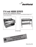
1
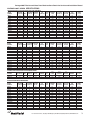
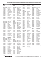
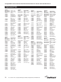
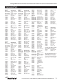
VANTAGE 6000™ AND
GLASS DOOR MERCHANDISERS
Service, Installation and Care Manual
Please read this manual completely before attempting to install or operate this equipment! Notify
carrier of damage! Inspect all components immediately. See page 2.
TION
A
M
R
O
T INF
N
A
T
R
O
USE
IMP
E
R
O
F
E
ONS!
I
T
C
READ B
U
R
NST
I
E
S
E
H
VE T
A
S
E
S
A
PLE
Effective Date March 2003
Vantage 6000™ Series and Glass Door Merchandisers Reach-Ins Service and Installation Manual
Contents
RECEIVING AND INSPECTING UNIT.................................. 2
MECHANICAL DATA ............................................................. 3
INSTALLATION...................................................................... 4
MAINTENANCE .................................................................... 4
OPERATION.......................................................................... 5
SHELF INSTALLATION ......................................................... 6
DEFROST TIMER ................................................................. 7
REFRIGERATOR AND FREEZER WIRING DIAGRAMS...... 8
REPLACEMENT PARTS LIST.......................................... 9-11
STANDARD LABOR GUIDELINES ..................................... 12
STANDARD WARRANTIES............................................ 13-14
AUTHORIZED PARTS DEPOTS ......................... BACK PAGE
Serial Number Location
On refrigeration and freezer storage units, the serial tag is
located on the upper left rear corner of the cabinet exterior.
Always have the serial number of your unit available when
calling for parts or service. A complete list of authorized
Delfield parts depots is shown on the back cover of this
manual.
Copyright ©2003 The Delfield Company. All rights reserved. Reproduction
without written permission is prohibited. Vantage 6000™ Series and Vantage
Merchandisers™, and Delfield are registered trademarks of The Delfield
Company
Receiving and Inspecting the Equipment
Even though most equipment is shipped crated, care should
be taken during unloading so the equipment is not damaged
while being moved into the building.
6.
7.
1.
2.
3.
4.
5.
2
Visually inspect the exterior of the package and skid or
container. Any damage should be noted and reported to
the delivering carrier immediately.
If damaged, open and inspect the contents with the
carrier.
In the event that the exterior is not damaged, yet upon
opening, there is concealed damage to the equipment
notify the carrier. Notification should be made verbally as
well as in written form.
Request an inspection by the shipping company of the
damaged equipment. This should be done within 10 days
from receipt of the equipment.
Check the lower portion of the unit to be sure legs or
casters are not bent.
8.
Also open the compressor compartment housing and
visually inspect the refrigeration package. Be sure lines
are secure and base is still intact.
Freight carriers can supply the necessary damage forms
upon request.
Retain all crating material until an inspection has been
made or waived.
Uncrating the Equipment
First cut and remove the banding from around the crate.
Remove the front of the crate material, use of some tools will
be required. If the unit is on legs remove the top of the crate
as well and lift the unit off the skid. If the unit is on casters it
can be "rolled" off the skid.
For customer service, call (800) 733-8829, (800) 773-8821, Fax (989) 773-3210, www.delfield.com
Vantage 6000™ Series and Glass Door Merchandisers Reach-Ins Service and Installation Manual
VANTAGE 6000™ SERIES SPECIFICATIONS
SOLID DOOR REACH-IN REFRIGERATORS AND FREEZERS
MODEL
NUMBER
VOLTAGE
(60HZ/1Ph) AMPS
STORAGE
CUBIC FT
SHELVES
SQ. FT.
# OF
SHELVES
UNIT
H.P.
BTU/HR
CABINET
LOAD
BTU/HR
SYSTEM
CAPACITY
EVAP
CAPACITY
BTU/TD
SHIP
WEIGHT
NEMA
PLUG
VRR1-S
115
6.0
20
12.1
3
1/5
555
2010
130/15
332
5-15P
VRR2-S
115
10.0
43
26.6
6
1/4
919
2898
150/19
498
5-15P
VRR3-S
115
16.0
63
41.0
9
1/5-1/4
1265
4191
150/28
694
5-20
5-15P
FREEZER
VFR1-S
115
7.8
20
12.1
3
1/3
907
1510
150/10
334
VFR2-S
115
11.0
43
26.6
6
1/2
1522
3177
200/16
558
5-15P
VFR3-S
115
7.8/11.0
63
41.0
9
1/3-1/2
2138
4037
250/16
766
2(5-15)P
VRR1R-S
115
4.0
20
12.1
3
1/5*
555
2010
130/15
274
NA
VRR2R-S
115
5.0
43
26.6
6
1/4*
919
2898
150/19
454
NA
VRR3R-S
115
13.0
63
41.0
9
3/4*
1265
4191
150/28
622
NA
VFR1R-S
115
5.9
20
12.1
3
1/3*
907
1510
150/10
274
NA
VFR2R-S
115
7.1
43
26.6
6
1/2*
1522
3177
200/16
454
NA
VFR3R-S
115
13.0
63
41.0
9
3/4*
2138
4037
250/16
622
NA
CABINET
LOAD
BTU/HR
SYSTEM
CAPACITY
BTU/HR
CAPACITY
BTU/TD
EVAP
SHIP
WEIGHT
NEMA
PLUG
REMOTE
FREEZER
*Recommended.
GLASS DOOR REACH-IN REFRIGERATORS AND FREEZERS
MODEL
NUMBER
VOLTAGE
(60HZ/1Ph) AMPS
STORAGE
CUBIC FT
SHELVES
SQ. FT.
# OF
SHELVES
UNIT
H.P.
VRR1-G
115
6.0
20
12.1
3
1/5
820
2010
130/15
338
5-15P
VRR2-G
115
10.0
43
26.6
6
1/4
1453
2898
150/19
548
5-15P
VRR3-G
115
16.0
63
41.0
9
1/5-1/4
2058
4191
150/28
774
5-20P
5-15P
FREEZER
VFR1-G
115
7.8
20
12.1
3
1/3
1340
1466
130/11
340
VFR2-G
115
11.0
43
26.6
6
1/2
2376
2894
150/19
614
5-20P
VFR3-G
2(115)
7.8-11.0
63
41.0
9
1/3-1/2
3365
3551
150/24
854
(2)5-15P
VRR1R-G
115
4.0
20
12.1
3
1/5*
820
2010
130/15
290
NA
VRR2R-G
115
5.0
43
26.6
6
1/4*
1453
2898
150/19
444
NA
VRR3R-G
115
9.0
63
41.0
9
3/4*
2058
4191
150/28
630
NA
VFR1R-G
115
5.9
20
12.1
3
1/3*
1340
1466
130/11
290
NA
VFR2R-G
115
7.1
43
26.6
6
1/2*
2376
2894
150/19
444
NA
VFR3R-G
*Recommended.
115
13.0
63
41.0
9
3/4*
3365
3551
150/24
630
NA
UNIT
H.P.
CABINET
LOAD
SYSTEM
CAPACITY
CAPACITY
BTU/TD
SHIP
WEIGHT
NEMA
PLUG
REMOTE
FREEZER
SLIDING GLASS DOOR REACH IN REFRIGERATORS
MODEL
NUMBER
VOLTAGE
(60HZ/1Ph) AMPS
STORAGE
CUBIC FT
SHELVES
SQ. FT.
# OF
SHELVES
BTU/HR
BTU/HR
EVAP
VRR2-SL
115
10
43
26.6
6
1/4
1516
2898
150/19
548
5-15P
VRR2R-SL
115
5
43
26.6
6
1/4*
1516
2898
150/19
444
NA
STORAGE
CUBIC FT
SHELVES
SQ. FT.
# OF
SHELVES
UNIT
H.P.
BTU/HR
CABINET
LOAD
BTU/HR
SYSTEM
CAPACITY
EVAP
CAPACITY
BTU/TD
SHIP
WEIGHT
NEMA
PLUG
*Recommended
GLASS DOOR MERCHANDISERS
MODEL
NUMBER
VOLTAGE
(60HZ/1Ph) AMPS
GRR1-G
115
6.0
20
12.1
3
1/5
820
2010
130/15
338
5-15P
GRR2-G
115
10.0
43
26.6
6
1/4
1453
2898
150/19
548
5-15P
GRR3-G
115
16.0
63
41.0
9
1/5-1/4
2058
4191
150/28
774
5-20P
5-15P
FREEZERS
GFR1-G
115
7.8
20
12.1
3
1/3
1340
1466
130/11
340
GFR2-G
115
11.0
43
26.6
6
1/2
2376
2894
150/19
614
5-15P
GFR3-G
(2)115
7.8-11.0
63
41.0
9
1/3-1/4
3365
3551
150/24
854
(2)5-15P
GRR1R-G
115
4.0
20
12.1
3
1/5*
820
2010
130/15
290
NA
GRR2R-G
115
5.0
43
26.6
6
1/4*
1453
2898
150/19
444
NA
GRR3R-G
115
9.0
63
41.0
9
3/4*
2058
4191
150/28
630
NA
GFR1R-G
115
5.9
20
12.1
3
1/3*
1340
1466
130/11
290
NA
GFR2R-G
115
7.1
43
26.6
6
1/2*
2376
2894
150/19
444
NA
GFR3R-G
*Recommended.
115
13.0
63
41.0
9
3/4*
3365
3551
150/24
630
NA
Remote
FREEZERS
For customer service, call (800) 733-8829, (800) 773-8821, Fax (989) 773-3210, www.delfield.com
3
Vantage 6000™ Series and Glass Door Merchandisers Reach-Ins Service and Installation Manual
Installation
Location
Be sure the location chosen has a floor strong enough to
support the total weight of the cabinet and its contents. Certain
cabinets with its contents in this line can weigh up to 1500
pounds. The floor must be capable of supporting twice that
weight.
Stabilizing
Some models are supplied on casters for your convenience,
ease of cleaning underneath and for mobility. It is very
important, however, that the cabinet be installed in a stable
condition with the front wheels locked while in use.
For the most efficient operation, be sure to provide good air
circulation inside and out.
Inside cabinet: Do not pack the equipment so full that air
cannot circulate.
Outside cabinet: Be sure that the unit has access to ample air.
Avoid hot corners and locations near stoves and ovens.
It is recommended that the unit be installed no closer than 2”
from any wall and should have a 12” clearance above. Avoid
exposing glass door units to direct sunlight. Direct sunlight
through the glass doors will make the ABS liner fade and
become brittle and will greatly reduce refrigeration efficiency.
Caster/leg installation
Units are normally shipped with casters and legs installed.
However, units that are shipped with the casters or legs loose
will require installation of those components. During installation
of the casters/legs the unit must be adequately stabilized.
Failure to do this could result in damage
to the equipment or serious injury to the
operator.
First, remove the two bolts from the bottom of the unit holding
it to the pallet. These bolts are located under the wood deck
on the pallet and can be loosened with a 3/4” open end or
socket wrench. Carefully slide the unit on the pallet until one
of the sets of four holes for the casters/legs are exposed. Take
the caster/leg and align the holes on its mounting plates with
the holes in the bottom of the unit. Using four 5/16-18 selfthreading bolts supplied with the unit secure the caster/leg to
the unit using a 1/2” open end or socket wrench. These bolts
will require considerable force to tighten. Repeat the process
on the other three casters/legs.
Leveling
A level cabinet looks better and performs more efficiently. It
also helps with the proper closing of the doors and prevents
undue strain on the unit. Place a level on top of the unit from
front to back and left to right. To level a unit on legs, turn the
foot counterclockwise to extend and clockwise to retract. The
foot can be turned with a 1” open end or adjustable wrench.
To level a unit on casters, four leveling shims are provided with
one and two door units, six shims are provided with three door
units. These shims are 1/16” thick galvanized plates 1 3/8”W x
3 3/4” L. Place the required number of shims under the proper
caster to level the unit. Once the unit is level loosen the four
mounting screws holding the caster to the rail on which the
caster(s) shims were placed. Remove the shims from under
the caster and insert between the mounting plate and the rail.
Tighten the mounting screws.
4
CAUTION
Should it become necessary to lay the unit on
its side or back for any reason, allow at least 24
hours before start-up to allow compressor oil to
flow back to the sump.
Electrical Connection
Refer to the amperage data on page 3, the serial tag, your
local code or the National Electrical Code to be sure the unit is
connected to the proper power source. A protected circuit of the
correct voltage and amperage must be run for connection of the
line cord, or permanent connection to the unit.
The temperature control must be turned off and
the unit disconnected from the power source
whenever performing service, maintenance
functions or cleaning the refrigerated area.
Field Reversing doors is not recommended and will
void product warranty.
Maintenance
The interior and exterior can be cleaned using soap and warm
water. If this isn’t sufficient, try ammonia and water or a nonabrasive liquid cleaner. When cleaning the exterior, always rub
with the “grain” of the metal to avoid marring the finish.
Do not use an abrasive cleaner because it will scratch the
metal and plastic.
Cleaning the condenser
In order to maintain proper refrigeration and energy performance the condensing unit must be cleaned regularly. Failure
to perform these cleanings could result in compressor failure
and/or product loss. At least every 30 days the condenser coil
should be cleaned of dust, dirt and grease. To perform this
service, disconnect the electrical power from the
unit. Remove the louver by taking out the top
screws and lifting off the bottom catches. Using
a vacuum or stiff brush remove dust and other
obstructions from the front of the condenser. If
the dirt is more stubborn a commercial condenser cleaner is
available, please consult your factory service person for more
information. When finished replace the louver and reconnect
the electrical power.
Door gaskets should be cleaned as required to maintain their
ability to seal properly. Do not use sharp tools or knives to
scrape the bellows as this may tear the gasket and eliminate
its ability to seal. A soft bristle brush and solution of soap and
water will keep the gaskets clean. Do not use full strength
de-greasing agents on the gasket.
For customer service, call (800) 733-8829, (800) 773-8821, Fax (989) 773-3210, www.delfield.com
Vantage 6000™ Series and Glass Door Merchandisers Reach-Ins Service and Installation Manual
Operation Information
CAUTION
Do not place hot pans on the white ABS liner. Do
not throw items into the storage area. Failure
to heed these recommendations could result in
damage to the interior of the cabinet or the blower
coil.
Operation
The electric defrost controller is preset at the factory to provide
a defrost cycle every 6 hours (4 defrosts per day). If it is necessary to change the number of defrosts due to unusual operating
conditions, it can be accomplished by adjusting switches as
shown on page 7.
Even under the most severe operating conditions
it should not be necessary to set the back-time
greater than 60 minutes. Consult the factory if
complete de-icing of the coil is not accomplished.
After plugging the unit in, the unit will operate immediately.
Temperature Control Instruction
Refrigerators: A thermostat, located at the top of the refrigerator evaporator housing, controls the temperature in the box. The
factory setting for the control is “4” and maintains about 38°F
(3°C) in the box. Set toward “1” for higher temperature and
toward “7” for lower temperatures.
Freezers: A thermostat, located at the top of the freezer on
the right hand side of the evaporator housing, controls the
temperature in the box. The factory setting for the control is “4”
and maintains about -3°F (-19°C) in the box. Set toward “1” for
higher temperature and toward “7” for lower temperatures.
Refrigeration cycle
During the refrigeration cycle, for a freezer, the timer supplies
power to the temperature control, evaporator fan motors and
activates the condensing unit as needed. The fan operates only
during the refrigeration cycle. Any door being opened turns off
the fan motors and turns on the interior light.
1) The temperature control allows for the coil clearing after
each off cycle and before the compressor runs again.
2) Evaporator fan motors run continually on refrigerators only.
3) Interior lights are activated by the jamswitch when any door
is opened.
4) The anti-sweat heater around each door opening cycles
with the compressor.
Defrost Cycle
When defrost control goes into defrost, power to the condensing
unit and evaporator fans is interrupted and the defrost heater
is energized. The defrost heater warms the evaporator coil
thereby melting all frost accumulated during the previous refrigeration cycle. Once all frost is eliminated, the temperature of
the coil continues to rise until it reaches 70°F (13°C). When this
temperature is sensed by the defrost limit control, the defrost
control switches to refrigeration mode.
CAUTION
Thermostat
Evaporator
Fan
Product
Stop Bar
Unit loading
When loading the top shelf, maintain 4” of space between the fan
guard and product. Do not allow product to pass stop bar on the back
of the shelf. No product should be placed between the back shelf
supports and center ribs in order to maintain good airflow. Failure to
keep this space can cause inconsistent food temperature from top to
bottom.
If for any reason the timer remains in defrost for a period of time
greater than 40 minutes, a back-up defrost termination is also
provided. It can be changed by adjusting the electric control
switches as shown on page 7.
Freezer Defrost Control
All freezers are equipped with an Air-o-tronics defrost timer for
automatic defrosting of the evaporator coil. See page 7. The
defrost timer cannot be adjusted to the time of day.
For customer service, call (800) 733-8829, (800) 773-8821, Fax (989) 773-3210, www.delfield.com
5
Vantage 6000™ Series and Glass Door Merchandisers Reach-Ins Service and Installation Manual
Shelf Installation -2 and 3 door units
6
For customer service, call (800) 733-8829, (800) 773-8821, Fax (989) 773-3210, www.delfield.com
Vantage 6000™ Series and Glass Door Merchandisers Reach-Ins Service and Installation Manual
Defrost Timer Programming Guide (all models)
A (2) 4 position dip switch provides user control of defrost duration and cycle time. The
selection is as follows.
Programming Example
Defrost
Time
O 1 2 3 4
N
Defrost Time
off
off
on
on
on
off
on
on
off
off
on
on
off
off
off
off
off
off
on
on
on
off
off
off
off
on
off
off
off
off
on
off
off
off
on
on
on
on
on
min
void
5
10
15
20
25
30
35
40
45
50
55
60
40 Minute Duration
6 Hour Frequency
Typical Sequence of Operation
Period
40 Min
Frost Build Time
Compressor
Defrost terminated by
time or temperature
Defrost
6 Hour Cycle
Next cycle begins
Defrost timer
Cycle Time
hrs
void
2
4
6
8
10
12
14
16
18
20
22
24
PB
DEFROST
INITIATE
LED
X
CYCLE
TIME
PURPLE
P2
O
N
off
off
off
off
on
off
off
off
on
on
on
on
on
1 2 3 4
off
off
off
off
off
on
on
on
off
off
off
off
on
DEFROST
TIME
O
N
off
off
on
on
on
off
on
on
off
off
on
on
off
1 2 3 4
NOTE: Dip switches shown in default positions.
CR
P3
DEFROST ON
INITATE
N
Dip Switch
Setting
off
on
off
on
on
on
off
on
off
on
off
on
off
O 1 2 3 4
N
P1
Dip Switch
Setting
off
on
off
on
on
on
off
on
off
on
off
on
off
Cycle
Time
WHITE
DEFROST
LINE N/O
COMPRESSOR
LINE N/O
BROWN
BLACK
YELLOW
BLACK
For customer service, call (800) 733-8829, (800) 773-8821, Fax (989) 773-3210, www.delfield.com
7
Vantage 6000™ Series and Glass Door Merchandisers Reach-Ins Service and Installation Manual
Wiring Diagram: Refrigerators
Remote units will have
a solenoid in place of
condensing unit.
Incandescent light standard on s/s
door. Fluorescent light standard on
glass doors.
Remote units
only.
WHITE
L1
N
G
CONDENSATE HEATER
FLUORSCENT LAMP
BALLAST
WHITE
RED
RED
BLUE
BLACK
HLS
DS
ENERGY SAVER SWITCH
BLACK
THERMOSTAT
INTERIOR LIGHT
WHITE
EVAP. FAN(S)
1 PER DOOR OPENING
WHITE
FRAME HEATER WHITE
BROWN
BROWN
SOL
COND
WHITE
WHITE
BLACK
SOL - SOLENOID VALVE
HLS - HIGH LIMIT SAFETY
COND - CONDENSING UNIT
DS - DOOR SWITCH
Display lights are on “G” models only. Solenoid
valve and condensate heaters are on remote models
only. Power cord may or may not be provided.
Wiring Diagram: Freezers
Remote units will have
a solenoid in place of
condensing unit.
Incandescent light standard
on s/s door. Fluorescent light
standard on glass doors.
Remote units
only.
Display lights are on “G” models only. Defrost limit
used with mechanical controls only. Solenoid and
condensate heaters are on remote models only.
Power cord may or may not be provided.
For customer service, call (800) 733-8829, (800) 773-8821, Fax (989) 773-3210, www.delfield.com
WHITE
G
L1
N
CONDENSATE HEATER
BLACK
RED
HLS
FLUORSCENT LAMP
BALLAST
DSI
PURPLE
1 2 3 4
SOL - SOLENOID VALVE
DLFD - DEFROST LIMIT, FAN DELAY
COND - CONDENSING UNIT
HLS - HIGH LIMIT SAFETY
DS - DOOR SWITCH
8
WHITE
WHITE
PURPLE
EVAP. FAN(S)
HLS
PURPLE
WHITE
BLUE
DLFD
WHITE
WHITE
CDEFROST HEATER
WHITE
1 PER DOOR OPENING
BLACK
ENERGY SAVER SWITCH
BROWN
THERMOSTAT
FRAME HEATER
WHITE
COND
BROWN
BROWN
COMPRESSOR
LINE N/O
BROWN
DEFROST
LINE N/O
LED
DEFROST
ON INITATE
CYCLE
TIME
O
N
PB
1 2 3 4
DEFROST
INITIATE
O
N
N
P1
X
P2
DEFROST CR
TIME
P3
SOL
WHITE
WHITE
Vantage 6000™ Series and Glass Door Merchandisers Reach-Ins Service and Installation Manual
Replacement Parts
VRR1-S
PART #
000-AB9-010A
000-AHA-020F
1701288
2162515
2194005
2194224
2194606
2194619
3233955
3234225
3234641
3234644
3234753
3234754
3516051
3516185
3516191
3516309
3516313
3526807
3977962
2194620
9321190
DESCRIPTION
Solid door, LH
Assy. louver 1-dr.
Gasket
Fan motor
Light bulb
Temp control
Rocker switch
Light socket
Pivot hinge, Bot. Rt
Hinge cart. assy.
Top hinge bracket
Caster
Door lock
Caster, w/ brake
Accumulator
Guard, fan
Filter dryer
Evap coil, 1-dr.
Dial thermometer
Cond. unit, 1-dr.
Wire shelf 1-dr.
Rocker switch
Screw, evap. hsng.
VRR2-S
000-AB9-010A
000-AB9-010C
000-AHA-020G
1701288
2162515
2194005
2194224
2194606
2194619
3233954
3233955
3234225
3234641
3234644
3234753
3234754
3516051
3516185
3516191
3516312
3516313
3526808
3977966
2194620
9321190
Solid door, RH
Solid door, LH
Assy. louver 2-dr.
Gasket
Fan motor
Light bulb
Temp control
Rocker switch
Light socket
Pivot hinge, Bot. Lt.
Pivot hinge, Bot, Rt.
Hinge cart. assy.
Top hinge bracket
Caster
Door lock
Caster, w/ brake
Accumulator
Guard, fan
Filter dryer
Evap. coil 2-dr.
Dial thermometer
Cond. unit, 2-dr.
Wire shelf 2-dr.
Rocker switch
Screw, evap. hsng.
VRR3-S
PART #
000-AB9-010A
000-AB9-010C
000-AHA-020K
1701288
2162515
2194005
2194224
2194606
2194619
3233954
3233955
3234225
3234641
3234644
3234753
3234754
3516051
3516185
3516191
3516309
3516312
3516313
3526807
3526808
3977962
3977966
2194620
9321190
DESCRIPTION
Solid door, RH
Solid door, LH
Assy. louver, 3-dr.
Gasket
Fan motor
Light bulb
Temp control
Rocker switch
Light socket
Pivot hinge, Bot. Lt.
Pivot hinge, Bot. Rt.
Hinge cart. assy.
Top hinge bracket
Caster
Door lock
Caster, w/ brake
Accumulator
Guard, fan
Filter dryer
Evap. coil, 1-dr.
Evap. coil, 2-dr.
Dial thermometer
Cond unit, 1-dr.
Cond unit, 2-dr.
Wire shelf 1-dr.
Wire shelf 2-dr.
Rocker switch.
Screw, evap. hsng.
VRR1-G
PART #
000-AB9-010F
000-AHA-020F
1701313
2162515
2193928
2193939
2193940
2194161
2194224
2194606
3233953
3234641
3234644
3234753
3234754
3516051
3516185
3516191
3516309
3516313
3526807
3977962
9321190
VRR2-G
PART #
000-AB9-010E
000-AB9-010F
000-AHA-020G
1701313
2162515
2193903
2193907
2193939
2193940
2194224
2194606
3233952
3233953
3234641
3234644
3234753
3234754
3516051
3516185
3516191
3516312
3516313
3526808
3977966
9321190
VRR3-G
PART #
000-AB9-010E
000-AB9-010F
000-AHA-020K
1701313
2162515
2193907
2193928
2193939
2193940
2194161
2194224
2194606
3233952
3233953
3234641
3234644
3234753
3234754
3516051
3516185
3516191
3516309
DESCRIPTION
Glass door, RH
Assy. louver 1-dr.
Door gasket
Fan motor
Lamp, bulb, 18”
Lampholder LH
Lampholder RH
Ballast
Temp control
Rocker switch
Bracket hinge,
Top/Lt. Bottom/Rt.
Top hinge bracket
Caster
Door lock
Caster, w/ brake
Accumulator
Guard, fan
Filter dryer
Evap coil, 1-dr. sect
Dial thermometer
Cond. unit
Wire shelf 1-dr.
Screw, evap hsng.
DESCRIPTION
Glass door LH
Glass door RH
Assy. louver 2-dr.
Door gasket
Fan motor
Ballast
Lamp, bulb 36”
Lampholder LH
Lampholder RH
Temp control
Rocker switch
Bracket hinge,
Top/Rt., Bottom/Lt.
Bracket Hinge
Top/Lt., Bottom/Rt.
Top hinge bracket
Caster
Door lock
Caster, w/ brake
Accumulator
Guard, fan
Filter dryer
Evap. coil, 2-dr.
Dial thermometer
Cond. unit
Wire shelf 2-dr.
Screw, evap. hsng.
DESCRIPTION
Glass door LH
Glass door RH
Assy. louver 3-dr.
Door gasket
Fan motor
Lamp, bulb 36”
Lamp, bulb, 18”
Lampholder LH
Lampholder RH
Ballast
Temp control
Rocker switch
Bracket hinge,
Top/Rt., Bottom/Lt.
Bracket Hinge
Top/Lt., Bottom/Rt.
Top hinge bracket
Caster
Door lock
Caster, w/ brake
Accumulator
Guard, fan
Filter dryer
Evap. coil, 1-dr.
3516312
3516313
3526807
3526808
3977962
3977966
9321190
VFR1-S
PART #
000-AB9-010A
000-AHA-020F
1701288
2162515
2194005
2194046
2194235
2194590
2194606
2194619
3233955
3234225
3234641
3234644
3234753
3234754
3516043
3516051
3516185
3516191
3516300
3516310
3516313
3526809
3977962
2194620
9321190
VFR2-S
PART #
000-AB9-010A
000-AB9-010C
000-AHA-020G
1701288
2162515
2194005
2194046
2194235
2194579
2194606
2194619
3233954
3233955
3234225
3234641
3234644
3234753
3234754
3516043
3516057
3516185
3516191
3516213
3516300
3516313
3526909
3977966
2194620
9321190
Evap. coil, 2-dr.
Dial thermometer
Cond. unit, 1-dr.
Cond. unit, 2-dr.
Wire shelf 1-dr.
Wire shelf 2-dr.
Screw evap. hsng.
DESCRIPTION
Solid door, RH
Assy. louver 1-dr.
Gasket
Fan motor
Light bulb
Fan delay/defrost
limit
Safety switch
Defrost heater 1-dr.
Rocker switch
Light socket
Pivot hinge, Bot. Rt.
Hinge cart. assy.
Top hinge bracket
Caster
Door lock
Caster, w/ brake
Temp control
Accumulator
Guard, fan
Filter dryer
Defrost timer
Evap coil, 1-dr..
Dial thermometer
Cond. unit, 1-dr.
Wire shelf 1-dr.
Rocker switch
Screw, evap. hsng.
DESCRIPTION
Solid door, RH
Solid door, LH
Assy. louver 2-dr.
Gasket
Fan motor
Light bulb
Fan delay/defrost
limit
Safety switch
Defrost heater 2-dr.
Rocker switch
Light socket
Pivot hinge
Pivot hinge
Hinge cart. assy.
Top hinge bracket
Caster
Door lock
Caster, w brake
Temp control
Accumulator
Guard, fan
Filter dryer
Freezer coil, 2-dr.
Defrost timer
Dial thermometer
Cond. unit, 2-dr.
Wire shelf, 2-dr.
Rocker switch
Screw, evap. hsng
VFR3-S
PART #
000-AB9-010A
000-AB9-010C
000-AHA-020K
1701288
2162515
2194005
2194046
2194235
2194579
2194590
2194606
2194619
3233954
3233955
3234225
3234641
3234644
3234753
3234754
3516043
3516051
3516157
3516185
3516191
3516213
3516300
3516310
3516313
3526809
3526909
3977962
3977966
2194620
9321190
VFR1-G
PART #
000-AB9-010H
000-AHA-020F
1701313
2162515
2193928
2193939
2193940
2194046
2194235
2194578
2194606
3233953
3234641
3234644
3234753
3234754
3516043
3516051
3516185
3516191
3516300
3516310
3516313
3526809
3977962
2194620
9321190
DESCRIPTION
Solid door, RH
Solid door, LH
Assy. louver 3-dr.
Gasket
Fan motor
Light bulb
Fan delay/defrost
limit
Safety switch
Defrost heater 2-dr.
Defrost heater 1-dr.
Rocker switch
Light socket
Pivot hinge, Bot. Lt.
Pivot hinge, Bot. Rt.
Hinge cart. assy.
Top hinge bracket
Caster
Door lock
Caster, w/ brake
Temp control
Accumulator
Accumulator
Guard, fan
Filter dryer
Evap. coil, 2-dr.
Defrost timer
Evap. coil, 1-dr.
Dial thermometer
Cond. unit, 1-dr.
Cond. unit, 2-dr.
Wire shelf 1-dr.
Wire shelf 2-dr.
Rocker switch
Screw, evap. hsng.
DESCRIPTION
Glass door, RH
Assy. louver 1-dr.
Gasket
Fan motor
Lamp, bulb, 18”
Lampholder LH
Lampholder RH
Fan delay/defrost
limit
Safety switch
Ballast
Rocker switch
Top hinge left
Top hinge bracket
Caster
Door lock
Caster, w/ brake
Temp control
Accumulator
Guard, fan
Filter dryer
Defrost timer
Evap coil, 1-dr.
Dial thermometer
Cond. unit, 1-dr.
Wire shelf 1-dr.
Rocker switch
Screw, evap. hsng.
For customer service, call (800) 733-8829, (800) 773-8821, Fax (989) 773-3210, www.delfield.com
9
Vantage 6000™ Series and Glass Door Merchandisers Reach-Ins Service and Installation Manual
Replacement Parts
VFR2-G
000-AB9-010G
000-AB9-010H
000-AHA-020G
1701313
2162515
2193907
2193939
2193940
2194046
2194239
2194606
3233952
3233953
3234641
3234644
3234753
3234754
3516043
3516057
3516185
3516191
3516213
3516300
3516313
3526909
3977966
2194620
9321190
2194235
VFR3-G
PART #
000-AB9-010G
000-AB9-010H
000-AHA-020K
1701313
2162515
2193907
2193928
2193939
2193940
2194046
2194235
2194578
2194579
2194590
2194606
3233952
3233953
3234641
3234644
3234753
3234754
3516043
3516051
3516157
3516185
3516191
3516213
3516310
3516300
3516313
3526809
3526909
3977962
3977966
2194620
9321190
10
Glass door LH
Glass door RH
Assy. louver 1-dr.
Gasket
Fan motor
Lamp, bulb 36”
Lampholder LH
Lampholder RH
Fan delay/defrost
limit
Heater defrost
Rocker switch
Bracket hinge,
Top/Rt., Bottom/Lt.
Bracket Hinge
Top/Lt., Bottom/Rt.
Hinge bracket
Caster
Door lock
Caster, w/ brake
Temp control
Accumulator
Guard, fan
Filter dryer
Evap. coil, 2-dr.
Defrost timer
Dial thermometer
Cond. unit, 2-dr.
Wire shelf 2-dr.
Rocker switch
Screw, evap. hsng.
Heater safety
DESCRIPTION
Glass door LH
Glass door RH
Assy. louver 3-dr.
Gasket
Fan motor
Lamp, bulb 36”
Lamp, bulb 18”
Lampholder LH
Lampholder RH
Fan delay/defrost
limit
Safety switch
Ballast
Defrost heater 2-dr.
Defrost heater 1-dr.
Rocker switch
Bracket hinge,
Top/Rt., Bottom/Lt.
Bracket Hinge
Top/Lt., Bottom/Rt.
Hinge bracket
Caster
Door lock
Caster, w/ brake
Temp. control
Accumulator
Accumulator
Guard, fan
Filter dryer
Evap. coil, 2-dr.
Evap. coil, 1-dr.
Defrost timer
Dial thermometer
Cond. unit, 1-dr.
Cond. unit, 2-dr.
Wire shelf 1-dr.
Wire shelf 2-dr.
Rocker switch
Screw, evap. hsng.
VRR1-SH
PART #
000-AB9-010B
000-AB9-010D
000-AHA-020F
000-AHE-0030
2162515
2194005
2194224
2194606
2194619
3233955
3234225
3234480
3234641
3234644
3234753
3234754
3516051
3516185
3516191
3516309
3516313
3526807
3977962
2194620
9321190
VRR2-SH
PART #
000-AB9-010B
000-AB9-010D
000-AHA-020G
1701289
2162515
2194005
2194224
2194606
2194619
3233954
3233955
3234225
3234479
3234480
3234641
3234644
3234753
3234754
3516051
3516185
3516191
3516312
3516313
3526808
3977966
2194620
9321190
DESCRIPTION
Solid door, Top/RT,
Bot/LT
Solid door, Bot/RT,
Top/LT
Assy. louver 1-dr.
Hor. mullion assy.
Fan motor
Light bulb
Temp control
Rocker switch
Light socket
Pivot hinge BTM/
RT
Hinge cartridge
assy.
Bracket 1/2 dr., RH
Hinge bracket top
Caster
Door lock
Caster, w/ brake
Accumulator
Guard, fan
Filter dryer
Evap. coil, 1-dr.
Thermometer
Cond. unit, 1-dr.
Wire shelf 1-dr.
Rocker switch
Screw, evap. hsng.
DESCRIPTION
Solid door, Top/RT,
Bot/LT
Solid door, Bot/RT,
Top/LT
Assy. louver 2-dr.
Gasket, door
Fan motor
Light bulb
Temp control
Rocker switch
Light socket
Pivot hinge, BTM/
LT
Pivot hinge BTM/
RT
Hinge cartridge
assy.
Bracket 1/2 dr., LH
Bracket 1/2 dr., RH
Hinge bracket top
Caster
Door lock
Caster, w/ brake
Accumulator
Guard, fan
Filter dryer
Evap. coil, 2-dr.
Thermometer
Cond. unit, 2-dr.
Wire shelf 2-dr.
Rocker switch
Screw, evap. hsng.
VRR3-SH
PART #
000-AB9-010B
000-AB9-010D
000-AHA-020K
1701289
2162515
2194005
2194224
2194606
2194619
3233954
3233955
3234225
3234479
3234480
3234641
3234644
3234753
3234754
3516051
3516185
3516191
3516309
3516312
3516313
3526807
3526808
3977962
3977966
2194620
9321190
VRR1-GH
PART #
000-AB9-010J
000-AB9-010N
000-AHA-020F
1701314
2162515
2193928
2193939
2193940
2194161
3233953
2194224
2194606
3233953
3234480
3234641
3234644
3234753
3234754
3516051
3516185
3516191
3516309
3516313
3526807
3977962
9321190
DESCRIPTION
Solid door, Top/RT,
Bot/LT
Solid door, Bot/RT,
Top/LT
Assy. louver 3-dr.
Gasket, door
Fan motor
Light bulb
Temp control
Rocker switch
Light socket
Pivot hinge, BTM/
LT
Pivot hinge BTM/
RT
Hinge cartridge
assy.
Bracket 1/2 dr., LH
Bracket 1/2 dr., RH
Hinge bracket top
Caster
Door lock
Caster, w/ brake
Accumulator
Guard, fan
Filter dryer
Evap. coil, 1-dr.
Evap. coil, 2-dr.
Thermometer
Cond. unit, 1-dr.
Cond. unit, 2-dr.
Wire shelf 1-dr.
Wire shelf 2-dr.
Rocker switch
Screw, evap. hsng.
DESCRIPTION
Glass door, Top/RT
Glass door, Bot/RT
Assy. louver 1-dr.
Gasket, door
Fan motor
Lamp bulb, 18”
Lampholder LH
Lampholder RH
Ballast
Hinge Top/Lt.
Bottom/Rt.
Temp control
Rocker switch
Hinge Top/LT BTM/
RT
Bracket 1/2 dr., RH
Hinge bracket top
Caster
Door lock
Caster, w/ brake
Accumulator
Guard, fan
Filter dryer
Evap. coil, 1-dr.
Thermometer
Cond. unit, 1-dr.
Wire shelf 1-dr.
Screw, evap. hsng.
For customer service, call (800) 733-8829, (800) 773-8821, Fax (989) 773-3210, www.delfield.com
VRR2-GH
PART #
000-AB9-010I
000-AB9-010J
000-AB90-010M
000-AB9-010N
000-AHA-020G
1701314
2162515
2193903
2193907
2193939
2193940
2194224
2194606
3233952
3233953
3234479
3234480
3234641
3234644
3234753
3234754
3516051
3516185
3516191
3516312
3516313
3526808
3977966
9321190
VRR3-GH
PART #
000-AB9-010I
000-AB9-010J
DESCRIPTION
Glass door, Top/LT
Glass door, Top/RT
Glass door, Bot/LT
Glass door, Bot/RT
Assy. louver 2-dr.
Gasket, door
Fan motor
Ballast
Lamp bulb, 36”
Lampholder LH
Lampholder RH
Temp control
Rocker switch
Hinge TOP/RT
BTM/LT
Hinge TOP/LT
BTM/RT
Bracket 1/2 dr., LH
Bracket 1/2 dr., RH
Hinge bracket top
Caster
Door lock
Caster, w/ brake
Accumulator
Guard, fan
Filter dryer
Evap. coil, 2-dr.
Thermometer
Cond. unit, 2-dr.
Wire shelf 2-dr.
Screw, evap. hsng.
DESCRIPTION
Glass door, TOP/LT
Glass door, TOP/
RT,
000-AB90-010M Glass door, TOP/LT
000-AB9-010N
Glass door, BOT/
RT
000-AHA-020K Assy. louver 3-dr.
1701314
Gasket, door
2162515
Fan motor
2193907
Lamp bulb 36”
2193928
Lamp bulb 18”
2193939
Lampholder LH
2193940
Lampholder RH
2194161
Ballast
2194224
Temp control
2194606
Rocker switch
3233952
Hinge TOP/RT
BOT/LT
3233953
Hinge TOP/LT
BOT/RT
3234479
Bracket 1/2 dr., LH
3234480
Bracket 1/2 dr., RH
3234641
Hinge bracket top
3234644
Caster
3234753
Door lock
3234754
Caster, w/ brake
3516051
Accumulator
3516185
Guard, fan
3516191
Filter dryer
3516309
Evap. coil, 1-dr.
3516312
Evap. coil, 2-dr.
3516313
Thermometer
3526807
Cond. unit, 1-dr.
3526808
Cond. unit, 2-dr.
3977962
Wire shelf, 1-dr.
3977966
Wire shelf 2-dr.
9321190
Screw, evap. hsng.
Vantage 6000™ Series and Glass Door Merchandisers Reach-Ins Service and Installation Manual
Replacement Parts
VFR1-SH
PART #
000-AB9-010B
000-AB9-010D
000-AHA-020F
1701289
2162515
2194005
2194046
2194235
2194590
2194606
2194619
3234225
3233955
3234480
3234641
3234644
3234753
3234754
3516043
3516051
3516185
3516191
3516300
3516310
3516313
3526809
3977962
5066440
9321190
VFR2-SH
PART #
000-AB9-010B
000-AB9-010D
000-AHA-020G
1701289
2162515
2194005
2194046
2194235
2194579
2194606
2194619
3233954
3233955
3234225
3234479
3234480
3234641
3234644
3234753
3234754
3516043
3516157
3516185
3516191
3516313
3516213
3516300
3526909
3977966
5066440
9321190
DESCRIPTION
Solid door, Top/RT,
Bot/LT
Solid door, Bot/RT,
Top/LT
Assy. louver 1-dr.
Door gasket
Fan motor
Light bulb
Fan delay/defrost
limit
Heater safety
switch
Defrost 1-dr.
Rocker switch
Light socket
Hinge cartridge
assy.
Hinge pivot BTM/
RT
Bracket 1/2 dr., RH
Hinge bracket top
Caster
Door lock
Caster, w/ brake
Temp control
Accumulator
Guard, fan
Filter dryer
Air-o-tronics timer
Evap. coil, 1-dr.
Thermometer
Cond. unit, 1-dr.
Wire shelf 1-dr.
Rocker switch
Screw, evap. hsng.
DESCRIPTION
Solid door, Top/RT,
Bot/LT
Solid door, Bot/RT,
Top/LT
Assy. louver 2-dr.
Gasket, door
Fan motor
Light bulb
Fan delay/defrost
limit
Heater safety
switch
Defrost 2-dr.
Rocker switch
Light socket
Pivot hinge, BTM/
LT
Pivot hinge BTM/
RT
Hinge cartridge
assy.
Bracket 1/2 dr., LH
Bracket 1/2 dr., RH
Hinge bracket top
Caster
Door lock
Caster, w/ brake
Temp control
Accumulator
Guard, fan
Filter dryer
Thermometer
Freezer coil
Air-o-tronics timer
Cond. unit, 2-dr.
Wire shelf 2-dr.
Rocker switch
Screw, evap. hsng.
VFR3-SH
PART #
000-AB9-010B
000-AB9-010D
000-AHA-020K
1701289
2162515
2194005
2194046
2194579
2194590
2194235
2194590
2194606
2194619
3233954
3233955
3234225
3234479
3234480
3234641
3234644
3234753
3234754
3516043
3516051
3516157
3516185
3516191
3516213
3516300
3516310
3516313
3526809
3526909
3977962
3977966
5066440
9321190
VFR1-GH
PART #
000-AB9-010L
000-AB9-010P
000-AHA-020F
1701314
2162515
2193928
2193939
2193940
2194046
2194235
2194578
2194590
2194606
2194619
3233953
3234480
3234641
3234644
3234753
3234754
3516043
3516157
3516185
3516191
3516300
DESCRIPTION
Solid door, Top/RT,
Bot/LT
Solid door, Bot/RT,
Top/LT
Assy. louver 3-dr.
Gasket, door
Fan motor
Light bulb
Fan delay/defrost
limit
Defrost heater 2-dr.
Defrost heater 1-dr.
Heater safety
switch
Defrost 1-dr.
Rocker switch
Light socket
Pivot hinge, BTM/
LT
Pivot hinge BTM/
RT
Hinge cartridge
assy.
Bracket 1/2 dr., LH
Bracket 1/2 dr., RH
Hinge bracket top
Caster
Door lock
Caster, w/ brake
Temp control
Accumulator
Accumulator
Guard, fan
Filter dryer
Evap. coil, 1-dr.
Air-o-tronics timer
Evap. coil, 1-dr.
Thermometer
Cond. unit, 1-dr.
Cond. unit, 2-dr.
Wire shelf 1-dr.
Wire shelf 2-dr.
Rocker switch
Screw, evap. hsng.
DESCRIPTION
Glass door, Top/RT
Glass door, Bot/RT
Assy. louver 1-dr.
Gasket
Fan motor
Lamp bulb, 18”
Lampholder LH
Lampholder RH
Fan delay/defrost
limit
Heater safety
switch
Ballast
Defrost heater
Rocker switch
Light socket
Hinge Top/LT BTM/
RT
Bracket 1/2 dr., RH
Hinge bracket top
Caster
Door lock
Caster, w/ brake
Temp control
Accumulator
Guard, fan
Filter dryer
Air-o-tronics timer
3516310
3516313
3526809
3977962
5066440
9321190
VFR2-GH
PART #
000-AB9-010K
000-AB9-010L
000-AB90-010O
000-AB9-010P
000-AHA-020G
1701314
2162515
2193907
2193939
2193940
2194046
2194235
2194579
2194606
3233952
3233953
3234479
3234480
3234641
3234644
3234753
3234754
3516043
3516157
3516185
3516191
3516213
3516300
3516313
3526909
3977966
5066440
9321190
Evap. coil, 1-dr.
Thermometer
Cond. unit, 1-dr.
Wire shelf 1-dr.
Rocker switch
Screw, evap. hsng.
DESCRIPTION
Glass door, Top/LT
Glass door, Top/RT
Glass door,
Glass door, Bot/RT,
Top/LT
Assy. louver 2-dr.
Gasket, door
Fan motor
Lamp bulb, 36”
Lampholder LH
Lampholder RH
Fan delay/defrost
limit
Heater safety
switch
Heater defrost
Rocker switch
Hinge TOP/RT
BTM/LT
Hinge TOP/LT
BTM/RT
Bracket 1/2 dr., LH
Bracket 1/2 dr., RH
Hinge bracket top
Caster
Door lock
Caster, w/ brake
Temp control
Accumulator
Guard, fan
Filter dryer
Evap. coil, 2-dr.
Air-o-tronics timer
Thermometer
Cond. unit, 2-dr.
Wire shelf 2-dr.
Rocker switch
Screw, evap. hsng.
VFR3-GH
PART #
000-AB9-010K
000-AB9-010L
DESCRIPTION
Glass door,
Glass door, Top/RT,
Bot/LT
000-AB90-010O Glass door, TOP/LT
000-AB9-010P
Glass door, BOT/
RT
000-AHA-020K Assy. louver 3-dr.
1701314
Gasket, door
2162515
Fan motor
2193907
Lamp bulb 36”
2193928
Lamp bulb 18”
2193939
Lampholder LH
2193940
Lampholder RH
2194046
Fan delay/defrost
limit
2194235
2194578
2194579
2194590
2194224
2194606
3233952
3233953
3234479
3234480
3234641
3234644
3234753
3234754
3516043
3516051
3516157
3516185
3516191
3516213
3516310
3516313
3516809
3526909
3977962
3977966
5066440
9321190
VRR2-SL
PART #
17011046
2162515
2193903
2193907
2193939
2193940
2194046
3234644
3234754
3455387
3516051
3516185
3516191
3516312
3516313
3526808
3977966
Hinge bracket top
Caster
Door lock
Caster, w/ brake
Temp control
Accumulator
Accumulator
Guard, fan
Filter dryer
Freezer coil
Evap. coil, 1-dr.
Thermometer
Cond. unit, 1-dr.
Cond. unit, 2-dr.
Wire shelf, 1-dr.
Wire shelf 2-dr.
Rocker switch
Screw, evap. hsng.
DESCRIPTION
Fluorescent light
36”
Fan motor
Ballast 36”
Fluorescent lamp
36”
Lampholder LH
Lampholder RH
Fan delay
Caster 3”
Caster 3”
Sliding glass door
2-dr
Accumulator
Thorgren blade
guard
Filter dryer
Refrigerator coil
Thermometer
Cond. unit
2-dr wire shelf
For remote units add the following
parts in addition to the listing.
2194199
Condensate evap.
element
3516041
Solenoid valve
Glass Door Merchandiser Units are
standard with legs, please use the
same listed numbers except replace
the caster part number with the following part number for a leg - 3234645.
Heater safety
switch
Ballast
Defrost heater 2-dr.
Defrost heater 1-dr.
Temp control
Rocker switch
Hinge TOP/RT
BOT/LT
Hinge TOP/LT
BOT/RT
Bracket 1/2 dr., LH
Bracket 1/2 dr., RH
For customer service, call (800) 733-8829, (800) 773-8821, Fax (989) 773-3210, www.delfield.com
11
Vantage 6000™ Series and Glass Door Merchandisers Reach-Ins Service and Installation Manual
STANDARD LABOR GUIDELINES TO REPAIR OR REPLACE PARTS ON DELFIELD EQUIPMENT
Advice and recommendations given by Delfield Service Technicians do not constitute or guarantee any special coverage.
• A maximum of 1-hour is allowed to diagnose a defective component.
• A maximum of 1-hour is allowed for retrieval of parts not in stock.
• A maximum travel distance of 100 miles round trip and 2-hours will be reimbursed.
• Overtime, installation/start-up, normal control adjustments, general maintenance, glass breakage, freight damage, and/or
correcting and end-user installation error will not be reimbursed under warranty unless pre-approved with a Service Work
Authorization from Delfield. You must submit the number with the service claim.
LABOR OF 1-HOUR IS ALLOWED TO REPLACE:
• Thermostat
• Infinite Switch
• Door Jamb Switch
• Solenoid Coil
• Hi-limit/Thermal Protector Switch
• Fan Delay/Defrost Termination Switch
• Compressor Start Components and Overload Protector
• Defrost Timer
• Thermometer
• Gear Box
LABOR OF 2 HOURS TO REPLACE:
• Drawer Tracks/Cartridges
• Pressure Control
• Solenoid Valve
LABOR OF 3 HOURS TO REPLACE:
• EPR or CPR Valve
• Expansion Valve
•
•
•
•
•
•
•
•
•
Contactor/Relay
Transformer
Evaporator/Condenser Fan Motor and Blade
Circulating Fan Motor and Blade
Microprocessor Control
Water Level Sensor/Probe
Door Hinges, Locks, and Gaskets
Condensate Element
Springs/Lowerator
• Defrost Element
• Heating Element
• Locate/Repair Leak
• Condenser or Evaporator Coil
LABOR OF 4 HOURS TO REPLACE
• Compressor
This includes recovery of refrigerant and leak check.
$35.00 maximum reimbursement for refrigerant recovery (includes recovery machine, pump, torch, oil, flux, minor fittings,
solder, brazing rod, nitrogen, or similar fees.)
REFRIGERANTS
• R22 A maximum of $4.00/lb. or 25¢/oz. will be reimbursed.
• R134A A maximum of $5.00/lb. or 31¢/oz. will be reimbursed.
• R404A A maximum of $12.00/lb. or 75¢/oz. will be reimbursed.
12
For customer service, call (800) 733-8829, (800) 773-8821, Fax (989) 773-3210, www.delfield.com
Vantage 6000™ Series and Glass Door Merchandisers Reach-Ins Service and Installation Manual
STANDARD ONE YEAR WARRANTY (ONE YEAR PARTS, ONE YEAR LABOR.)
The Delfield Company (“Delfield”) warrants to the Original Purchaser
of the Delfield product (herein called the “Unit”) that such Unit, and all
parts thereof, will be free from defects in material and workmanship
under normal use and service for a period of one (1) year from
the date of shipment of the Unit to the Original Purchaser or, if the
Original Purchaser returns the warranty card completely filled out
including the date of installation within thirty (30) days of receipt
of the Unit, one (1) year from the date of installation. During this
one year warranty period, Delfield will repair or replace any defective
part or portion there of returned to Delfield by the Original Purchaser
which Delfield determines was defective due to faulty material or
workmanship. The Original purchaser will pay all labor, crating, freight
and related costs incurred in the removal of the Unit of defective
component and shipment to Delfield, except that during a period of
either ninety (90) days from the date of shipment of the Unit to the
Original Purchaser or, if the Original Purchaser returns the warranty
card completely filled out including the date of installation within thirty
(30) days of receipt of the Unit, ninety (90) days from the date of
installation Delfield will pay all related labor costs. Delfield will pay the
return costs if the Unit or part thereof was defective.
The term “Original Purchaser” as used herein means that person, firm,
association, or corporation for whom the Unit was originally installed.
This warranty does not apply to any Unit or part thereof that has
been subjected to misuse, neglect, alteration, or accident, such as
accidental damage to the exterior finish, operated contrary to the
recommendations specified by Delfield; or repaired or altered by anyone
other than Delfield in any way so as to, in Delfield’s sole judgement,
affect its quality or efficiency. This warranty does not apply to any Unit
that has been moved from the location where it was originally installed.
This warranty also does not cover the refrigerator drier or the light
bulbs used in the Unit. The warranty is subject to the user’s normal
maintenance and care responsibility as set forth in the Service and
Installation Manual, such as cleaning the condenser coil, and is in
lieu of all other obligations of Delfield. Delfield neither assumes, nor
authorizes any other person to assume for Delfield, any other liability
in connection with Delfield’s products.
Removal or defacement of the original Serial Number or Model Number
from any Unit shall be deemed to release Delfield from all obligations
hereunder or any other obligations, express or implied.
Parts furnished by suppliers to Delfield are guaranteed by Delfield only
to the extent of the original manufacturer’s express warranty to Delfield.
Failure of the Original Purchaser to receive such manufacturer’s express
warranty to Delfield. Failure of the Original Purchaser to receive such
manufacturers warranty shall in no way create any warranty, expressed
or implied, or any other obligation or liability on Delfield’s part in respect
thereof.
IF THE CUSTOMER IS USING A PART THAT RESULTS IN A VOIDED
WARRANTY AND A DELFIELD AUTHORIZED REPRESENTATIVE
TRAVELS TO THE INSTALLATION ADDRESS TO PERFORM WARRANTY
SERVICE, THE SERVICE REPRESENTATIVE WILL ADVISE CUSTOMER
THE WARRANTY IS VOID. SUCH SERVICE CALLS WILL BE BILLED
TO CUSTOMER AT THE AUTHORIZED SERVICE CENTER’S THEN
APPLICABLE TIME AND MATERIALS RATES. CONSIDER: CUSTOMER
MAY INITIATE A SERVICE AGREEMENT WITHOUT PARTS COVERAGE.
If shipment of a replacement part is requested prior to the arrival in
the Delfield factory of the part claimed to be defective, the Original
Purchaser must accept delivery of the replacement part of a C.O.D.
basis, with credit being issued after the part has been received and
inspected at Delfield’s plant and determined by Delfield to be within this
warranty.
Under no condition does this warranty give the Original Purchaser the
right to replace the defective Unit with a complete Unit of the same
manufacturer or of another make. Unless authorized by Delfield in
writing, this warranty does not permit the replacement of any part,
including the motor-compressor, to be made with the part of another
make or manufacturer.
No claims can be made under this warranty for spoilage of any products
for any reason, including system failure.
The installation contractor shall be responsible for building access,
entrance and field conditions to insure sufficient clearance to allow any
hood(s), vent(s), or Unit(s) if necessary, to be brought into the building.
Delfield will not be responsible for structural changes or damages
incurred during installation of the Unit or any exhaust system.
Delfield shall not be liable in any manner for any default or delay in
performance hereunder caused by or resulting from any contingency
beyond Delfield’s control, including, but not limited to, war,
governmental restrictions or restraints, strike, lockouts, injunctions,
fire, flood, acts of nature, short or reduced supply of raw materials, or
discontinuance of the parts by the original part manufacturer.
Except as provided in any Additional Four Year Protection Plan,
if applicable, and the Service Labor Contract, if applicable, the
foregoing is exclusive and in lieu of all other warranties, whether
written or oral, express or implied. This warranty supersedes
and excludes any prior oral or written representations or
warranties. Delfield expressly disclaims any implied warranties
of merchantability, fitness for a particular purpose of compliance
with any law, treaty, rule or regulation relating to the discharge of
substances into the environment. The sole and exclusive remedies
of any person relating to the Unit, and the full liability of Delfield for
any breach of this warranty, will be as provided in this warranty.
Other than this Delfield Standard One Year Limited Warranty, any
applicable Delfield Additional Four Year Protection Plan or applicable
Delfield Service Labor Contract, the Original Purchaser agrees and
acknowledges that no other warranties are offered or provided in
connection with or for the unit or any other part thereof.
In no event will Delfield be liable for special, incidental or consequential
damages, or for damages in the nature of penalties.
IF DURING THE WARRANTY PERIOD, CUSTOMER USES A PART FOR
THIS DELFIELD EQUIPMENT OTHER THAN AN UNMODIFIED NEW
OR RECYCLED PART PURCHASED DIRECTLY FROM DELFIELD OR
ANY OF ITS AUTHORIZED SERVICE CENTERS AND/OR THE PART
BEING USED IS MODIFIED FROM ITS ORIGINAL CONFIGURATION,
THIS WARRANTY WILL BE VOID. FURTHER, DELFIELD AND ITS
AFFILIATES WILL NOT BE LIABLE FOR ANY CLAIMS DAMAGES OR
EXPENSES INCURRED BY THE CUSTOMER WHICH ARISE DIRECTLY
OR INDIRECTLY, IN WHOLE OR IN PART, DUE TO THE INSTALLATION
OF ANY MODIFIED PART AND/OR PART RECEIVED FROM AN
UNAUTHORIZED SERVICE CENTER. If the warranty becomes void,
Customer may purchase from Delfield, if available, a Service
Agreement or service at the then current time and materials rate.
For more information on Delfield warranty’s log on and check out the
service section of our web site at www.delfield.com.
For customer service, call (800) 733-8829, (800) 773-8821, Fax (989) 773-3210, www.delfield.com
13
Vantage 6000™ Series and Glass Door Merchandisers Reach-Ins Service and Installation Manual
ADDITIONAL FOUR YEAR PROTECTION PLAN
Delfield Model#
Serial #
Installation
Date
In addition to the Standard One Year Warranty on the MotorCompressor contained in the above listed Delfield product (the
“Unit”), The Delfield Company (“Delfield”) also agrees to repair, or
exchange with similar or interchangeable parts in design and capacity
at Delfield’s option, the defective Motor-Compressor contained in the
Unit (the “Motor-Compressor), or any part thereof, for the Original
Purchaser only, at any time during the four (4) years following the
initial one (1) year period commencing on the date of installation for
the Original Purchaser. Failure of the Original Purchaser to register
the registration card containing the Original Purchasers name,
address, date of installation, model number and serial number of
the Unit containing the Motor-Compressor within 30 days from the
date of installation shall void this warranty. This additional warranty
is only available if the Motor-Compressor is inoperative due to defects
in material or factory workmanship, as determined by Delfield in
its sole judgement and discretion. The Original Purchaser shall be
responsible for returning the defective Motor-Compressor to Delfield
prepaid, F.O.B. at the address shown on the back cover of this manual.
The term “Original Purchaser” as used herein means that person, firm,
association, or corporation for whom the Unit was originally installed.
The term “Motor-Compressor” as used herein does not include unit
base, air or water cooled condenser, receiver, electrical accessories
such as relay, capacitors, refrigerant controls, or condenser fan/motor
assembly. This warranty does not cover labor charges incidental to
the replacement of parts. This warranty further does not include
any equipment to which said condensing unit is connected, such as
cooling coils, temperature controls or refrigerant metering devices.
This warranty shall be void if the Motor-Compressor, in Delfield’s
sole judgement, has been subjected to misuse, neglect, alteration
or accident, operated contrary to the recommendations specified
by the Unit manufacturer, repaired or altered by anyone other than
Delfield in any way so as, in Delfield’s sole judgment, to affect its
quality or efficiency or if the serial number has been altered, defaced
or removed. This Warranty does not apply to a Motor-Compressor in
any Unit that has been moved from the location where it was originally
installed. The addition of methyl chloride to the condensing unit or
refrigeration system shall void this warranty.
14
(FOR MOTOR-COMPRESSOR ONLY)
General Conditions
Delfield shall not be liable in any manner for any default or delay
in performance hereunder caused by or resulting from any
contingency beyond Delfield’s control, including, but not limited
to, war, governmental restrictions or restraints, strike, lockouts,
injunctions, fire, flood, acts of nature, short or reduced supply
of raw materials, or discontinuance of any part or the MotorCompressor by the unit manufacturer.
Replacement of a defective Motor-Compressor is limited to one (1)
Motor-Compressor by us during the four (4) year period. Delfield
shall replace the Motor-Compressor at no charge.
This warranty does not give the Original Purchaser of the MotorCompressor the right to purchase a complete replacement MotorCompressor of the same make or of another make. It further does
not permit the replacement to be made with a Motor-Compressor
of another kind unless authorized by Delfield. In the event Delfield
authorizes the Original Purchaser to purchase a replacement
Motor-Compressor locally, only the wholesale cost of the MotorCompressor is refundable.
Expressly excluded from this warranty are damages resulting from
spoilage of goods.
Except as provided in any applicable Standard One Year Limited
Warranty or applicable Service Labor Contract, the foregoing
is exclusive and in lieu of all other warranties, whether written
or oral, express or implied. This Warranty supersedes and
excludes any prior oral or written representations or warranties.
Delfield expressly disclaims any implied warranties of
merchantability, fitness for a particular purpose or compliance
with any law, treaty, rule or regulation relating to the MotorCompressor, and the full liability of Delfield for any breach of this
warranty, will be as provided in this warranty.
Other than any applicable Delfield Standard One year Limited
Warranty, this Delfield Additional Four Year Protection Plan and any
applicable Delfield Service Labor Contract, the Original Purchaser
agrees and acknowledges that no other warranties are offered or
provided in connection with or for the Motor-Compressor or any
part thereof.
In no event will Delfield be liable for special, incidental or
consequential damages, or for damages in the nature of penalties.
For customer service, call (800) 733-8829, (800) 773-8821, Fax (989) 773-3210, www.delfield.com
Vantage 6000™ Series and Glass Door Merchandisers Reach-Ins Service and Installation Manual
NOTES
For customer service, call (800) 733-8829, (800) 773-8821, Fax (989) 773-3210, www.delfield.com
15
Delfield Authorized Parts Depots
NORTH
AMERICA
12
10
4
4
8
5
1
11
6
2
3
14
13
7
9
12
1) The Delfield Company
980 South Isabella Road
Mt. Pleasant, MI 48858
800.733.8829
989.773.7981
989.773.3210 FAX
custom parts direct from Delfield
5) Contract Ice
2) A.I.S. Commercial Parts & Service
3) Appliance Installation Service
4) Pacific Coast Parts
1816 West 26th Street
Erie, PA 16508-1149
800.332.3732
814.456.3732
814.452.4843 FAX
1336 Main Street
Buffalo, NY 14209
800.722.1252
716.884.7425
716. 884.0410 FAX
serves: MD, NJ, OH, PA, VA, WV
serves: CT, DC, DE, MA, MD, ME,
15024 Staff Court
Gardena, CA 90248
1.800.531.1111
1.800.782.5747
Email: [email protected]
www.pacparts.com
NH, NJ, NY, PA, RI, VA, VT, WV
serves: AZ, CA, HI, NV, OR
6) E.M.C.O. Sales & Distributors
7) Stove Parts Supply/GCS Service
14450 Ewing Ave S. #100
Burnsville, MN 55306
800.422.2823
952.894.4427
952.894.2164 FAX
3909 St. Timothy Lane
St. Ann, MO 63074
800.972.7670
314.427.7477
314. 427.8190 FAX
2120 Solona St.
PO Box 14009
Fort Worth, TX 76117-0009
1.800.433.1804 toll free
1.800.272.7358 fax
serves: IA, MN, MT, ND, SD, WI
serves: AR, IA, IL, KS,
serves: AR, LA, NM, OK, TX
8) Garland Group
1177 Kamato Road
Mississauga, Ontario L4W1X4
800.427.6668
800.361.7745 FAX
serves: Canada
KY, MO, NE, OK, TX, NM, LA
9) Global Parts and Supplies
11) MicroDine, Inc.
10) Hawkins Commercial Appl. Serv.
2920 N.W. 109th Avenue
Miami, FL 33172
305 994.9994
305.994.9992 FAX
3000 S. Wyandot
Englewood, CO 80110
(800) 624-2117
(303) 7618861 FAX
International parts depot
serves: AZ, CO, KS, NE, NM, OK, UT, WY
44792 Helm
Plymouth, MI 48170
888.828.4454
734.451.2043
734.451.3215 FAX
serves: MI, IN, WI, OH
13) Southeastern Restaurant Services
14) T.M.A.
2200 Norcross Parkway, Suite 210
Atlanta, GA 30071
800.235.6516
770.446.6177
770.446.3157 FAX
2916 Sidco Drive
Nashville, TN 37204
615.726.0351
800.737.0351
615.259.4100 FAX
serves: FL, GA, MS, NC, SC, VA
serves: TN, AL
12) Performance Refrigeration Parts
9923 S.W. 178th St.
Vashon, WA 98070
888.872.2465
206-463-1772
206.463.4431 FAX
serves: AK, HI, ID, MT, OR, WA
Delfield has 14 conveniently located Parts Depots to
ensure parts are handled promptly and accurately.
Delfield reserves the right to update or make changes
to this list without prior notice
Please call 1-800-733-8829 or check the web at www.delfield.com
for a list of the current Parts Depots.
980 S. Isabella Rd., Mt. Pleasant, MI 48804-0470, U.S.A. • (989) 773-7981 or (800) 733-8821 • Fax (800) 669-0619 • www.delfield.com
Delfield reserves the right to make changes in design or specifications without prior notice. 2003 The Delfield Company. All rights reserved. Printed in the U.S.A.
DMVAN 6/03