1
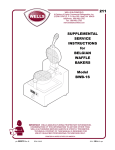
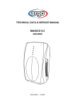
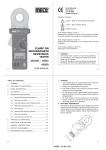
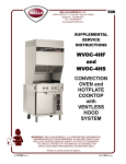
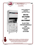
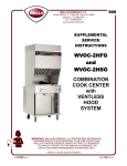
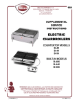
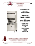
WELLS BLOOMFIELD
A Division of Carrier Commercial Refrigeration, Inc.
2 ERIK CIRCLE, P. O. Box 280 Verdi, NV 89439
telephone: 888-492-2782
fax: 888-492-2783
www.wellsbloomfield.com
212
SUPPLEMENTAL
SERVICE
INSTRUCTIONS
for
WAFFLE
BAKERS
Model
WB-1
WB-2
0
1
2
W
EL
LS
W
EL
LS
0
1
2
IMPORTANT: WELLS MANUFACTURING PROPRIETARY INFORMATION.
DISSEMINATION OF THIS INFORMATION TO ANYONE OTHER THAN
WELLS AUTHORIZED SERVICE AGENTS IS STRICTLY PROHIBITED.
TECHNICAL CONTENT OF THIS MANUAL IS DESIGNED FOR
USE BY QUALIFIED PROFESSIONAL TECHNICIANS ONLY.
PRINTED IN UNITED STATES OF AMERICA
p/n 502973 Rev. A
ECN-13145
S211
060921
cps
PRECAUTIONS AND GENERAL INFORMATION
RISK OF
PERSONAL INJURY
Installation procedures must
be performed by a qualified
technician with full knowledge
of all applicable electrical and
plumbing codes. Failure can
result in personal injury and
property damage.
WARNING:
ELECTRIC
SHOCK HAZARD
All servicing requiring
access to non-insulated
electrical components must
be performed by a qualified
technician.
Only qualified technicians are
authorized to open any
access panel which requires
the use of tools. Failure to
follow this warning can result
in severe electrical shock.
CAUTION:
RISK OF
DAMAGE
DO NOT connect or
energize this appliance until
all installation instructions are
read and followed. Damage
to the appliance will result if
these instructions are not
followed.
This appliance is intended for use in commercial establishments
only.
This appliance is intended to prepare food for human consumption.
No other use is recommended or authorized by the manufacturer or its
agents.
Operators of this appliance must be familiar with the appliance use,
limitations and associated restrictions. Operating instructions must be
read and understood by all persons using or installing this appliance.
Cleanliness of this appliance is essential to good sanitation. Read and
follow all included cleaning instructions and schedules to ensure the
safety of the food product.
Disconnect this appliance from electrical power before performing any
maintenance or servicing.
DO NOT submerge this appliance in water. Do not splash or pour
water on, in or over any controls, control panel or wiring.
Never use a wire brush or metal scraper on aluminum components.
Use bristle or fiber brush to clean grids.
The technical content of this manual, including any wiring diagrams,
schematics, parts breakdown illustrations and/or adjustment
procedures, is intended for use by qualified technical personnel.
Any procedure which requires the use of tools must be performed by a
qualified technician.
This appliance is made in the USA. Unless otherwise noted, this
appliance has American sizes on all hardware.
Information in this manual reflects current production models as of
September 1, 2006. Specifications, model numbers, product numbers
and data subject to change without notice.
xi
212 5029732 SvcManual for WB-1, -2 Waffle Bakers
WARNING:
TABLE OF CONTENTS
Precautions & General Information ……………………………
Electrical Specifications ..………………………………………..
Features & Operating Controls ………………………………….
Operational Tests …………………………………………...…….
Servicing Instructions
Cabinet ………………………………………………………….
Back Panel & Solid State Controls ………………………….
Grids …………………………………………………………….
Cook Head Pivot ………………………………………………
Bypass Hi-Limit Thermostat (older units) …………………..
Wiring Diagram ……………………………………………..…….
Exploded Views & Parts Lists …………………………………..
xi
1
2
3
5
6
7
9
10
11
12
INTRODUCTION
This manual contains information needed to properly service and repair Wells Belgian Waffle Bakers.
This manual applies to the following Wells Manufacturing models:
WB-1
WB-2
For installation, operation and maintenance instructions, refer to Operation Manual p/n 37055.
SPECIFICATIONS
GENERAL DIMENSIONS:
212 5029732 SvcManual for WB-1, -2 Waffle Bakers
WB-1
WB-2
10-1/8” Wide x 16” Deep x 8-3/4” High
Appliance is 18-3/4” High with grid open.
19-13/16” Wide x 16” Deep x 8-3/4” High
Appliance is 18-3/4” High with grid open.
MODEL
STYLE
WB-1
Single
Waffle Baker
WB-2
Double
Waffle Baker
VOLTAGE
1ø
WATTS
AMPS
POWER SUPPLY
CORD
120 VAC
900 W
7.5 A
NEMA 5-15P
208 VAC
676 W
3.25 A
NEMA 6-15P
240 VAC
900 W
3.75 A
NEMA 6-15P
120 VAC
1800 W
15 A
NEMA 5-20P
208 VAC
1352 W
6.5 A
NEMA 6-15P
240 VAC
1800 W
7.5 A
NEMA 6-15P
Refer to Wells General Layout Data sheet, p/n 37093 for current specifications.
1
FEATURES & OPERATING CONTROLS
24
28
18
19
12
33
50
6
37
23
ITEM
DESCRIPTION
COMMENTS
6
THERMOSTAT
Maintains baking temperature; adjustable (see page 3)
12
LOWER GRID ASSEMBLY
Lower cooking element; contains thermostat
18
UPPER GRID ASSEMBLY
Upper cooking element
19
GRID HANDLE
Used to safely raise / lower grid
23
DRIP TRAY
Catches excess waffle batter; removable for easier cleaning
24
POWER SWITCH
Energize / de-energize waffle baker
28
HINGE ASSEMBLY
Supports upper grid; allows grid to be raised/lowered for baking
33
DATA PLATE
Lists manufacturer information, agency approvals and electrical specifications
37
TIMER
Mechanical “bell” timer; rings to indicated end of cook cycle
44
RUBBER FEET
Provide means of leveling waffle baker; provide non-slip support
50
POWER CORD
115VAC NEMA 5-15P or 5-20P / 208/240VAC NEMA 6-15P
2
212 5029732 SvcManual for WB-1, -2 Waffle Bakers
44
OPERATIONAL CHECKS
A. AMPERAGE CHECKS
CAUTION:
1. Waffle Baker sections are tested separately. Use WB-1 amperage
rating when testing an individual Waffle Baker section.
ELECTRIC SHOCK
HAZARD
2. Total amperage may be checked with an inductive amperage tester
(Amprobe™ or similar) by encircling a single wire at the power
switch.
3. Make all testing hookups with the Waffle Baker unplugged and
when the cooking surfaces are cold.
Live electric circuits may
be exposed during these
procedures. Take necessary
precautions to avoid electric
shock.
CAUTION:
B. TEMPERATURE CHECKS
BURN HAZARD
HOT SURFACES
1. Desired baking temperature is 390ºF ±5ºF (200ºC ±3ºC).
Equipment surfaces may be hot
during these procedures. Take
necessary precautions to
avoid burns.
2. Turn the power switch ON and allow Waffle Baker to heat for a
minimum of 30 minutes. Insert a pyrometer of known accuracy
between the closed grids and allow the readings to stabilize.
3. Temperature may be adjusted by inserting a 3/16” nutdriver
through the hole in the bottom panel of the Waffle Baker and
turning the shaft of the thermostat (item 6).
VOLTAGE
C. VOLTAGE TEST POINTS
TOP GRID ASSEMBLY
BOTTOM GRID ASSEMBLY
AMPERAGE
WB-1 WB-2
120
7.5
15.0
208
3.3
6.5
240
3.8
7.5
THERMOSTAT
TP 1T
TP 2T
TP 3
TP 4
212 5029732 SvcManual for WB-1, -2 Waffle Bakers
TP 1B
TP 2B
D. VOLTAGE CHECKS - 120V unit
(208/240 similar - see wiring diagram)
1. Voltage between TP 1T and TP2T will be 120V when thermostat is
calling for heat.
2. Voltage between TP 1B and TP2B will be 120V when thermostat
is calling for heat.
3. Voltage between TP3 and TP4 will be 120V when thermostat is
satisfied, and 0V when thermostat is calling for heat.
4. Voltage between TP4 and TP 2B will be 120V when thermostat is
calling for heat.
5. Voltage between TP3 and TP 2B will be 120V whenever power
switch is ON.
3
IMPORTANT:
Always unplug appliance
from electric power and
momentarily ground all three
prongs of the power cord
before attempting resiatance
checks.
OPERATIONAL CHECKS (continued)
CAUTION:
E. EVALUATING THE RESULTS
ELECTRIC SHOCK
HAZARD
1. Presence of 120V in Test #1 or Test #2 (calling for heat but
element not heating) indicates a defective element.
CAUTION:
BURN HAZARD
HOT SURFACES
Equipment surfaces may be hot
during these procedures. Take
necessary precautions to
avoid burns.
2. Absence of 120V in Test #1 or Test #2 when calling for heat
indicates:
a.) power switch defective or OFF; or,
b.) thermostat is defective; or,
c.) a wiring or connector problem
3. Any reading other than 0V in Test #3 when calling for heat
indicates a defective thermostat.
4. Absence of 120V in Test #4 when calling for heat indicates:
a.) power switch defective or OFF; or,
b.) thermostat is defective; or,
c.) a wiring or connector problem
5. Absence of 120V in Test #5 whenever power switch ON indicates:
a.) power switch defective or OFF; or,
b.) a wiring or connector problem
F. TROUBLESHOOTING SUGGESTIONS
1. In 208/240V units, the elements are wired in series: in 120V units,
the elements are wired in parallel.
Amperage readings 1/2 of normal indicate a 208/240V unit
operating on 120V, or possible electrical problems in either the top
or bottom grid assembly. Wiring investigation, as well as voltage
and resistance measurements, may be required to isolate the ex
act problem.
2. Amperage readings significantly above normal indicate either a unit
operating on the wrong voltage, a partial short, or a deteriorated
heating element. Again, voltage and resistance measurements will
be required to pinpoint the problem.
3. Failure of an individual grid assembly to heat indicates electrical
or component problems in that area. Voltage measurements will
be required to isolate the exact problem.
4. Grids which heat, but do not come up to temperature, indicate
either a defective element or a defective thermostat.
5. Grids which overheat uncontrollably indicate either a defective
thermostat or an electrical short.
4
212 5029732 SvcManual for WB-1, -2 Waffle Bakers
Live electric circuits may
be exposed during these
procedures. Take necessary
precautions to avoid electric
shock.
SERVICING INSTRUCTIONS
CAUTION:
A. TOP GRID ASSEMBLY
ELECTRIC SHOCK
HAZARD
Unplug appliance from
electric power before
removing any panel or
access cover.
CASTING AND HINGE ASSEMBLY
CASTING, TOP 1
P/N 50327
SOLID CONDUIT
P/N 55547
CONDUIT, CAST
P/N 50329
Insert small diameter end
into hinge
30
Pull ground wire up to center
Ground wire gets 4“ of
FIBERGLASS SLEEVE
P/N 54573 (rl 100ft)
after it is pulled into casting
32
7
7
6
Pull power wires up
above casting numbers
Power wires get 9“ of
RUBBERIZED SLEEVE
P/N 50284 (rl 10 ft)
2
Ground wire
3
HINGE PLUG
P/N 50328
4
HINGE
P/N 50322
SCREW 8-32
P/N 51715 (pk 100)
5
GRID & ELEMENT ASSEMBLY
8
GRID, TOP P/N 50454
212 5029732 SvcManual for WB-1, -2 Waffle Bakers
9
GASKET, GRID P/N 50337
Check to insure gasket is
installed flush around casting
10
INSULATION PAD,
WB ELEMENT TOP
P/N 50430
11 ELEMENT,
120V 450W P/N 50450
Check for correct voltage
and wattage.
Assemble so that terminals
will be on side of hinge with
solid conduit.
NOTE: Washer
12 CLAMP PLATE, TOP
P/N 50431
13 SCREW, 8-32 x 5/16“ P/N 51715 (pk 100)
Do not tighten until all screws are in place.
Trap ground wire under this screw.
Ensure that element terminals are centered
in opening before tightening.
14 Insert stud on clamping plate of Grid & Element Assembly
into hole in top casting of Casting & Hinge Assembly.
Ensure that gasket is evenly seated, then secure assemblies
with TenzNut (RING, RETAINING P/N 50222 pk 10).
Insert PLUG, TOP CASTING P/N 58628
5
SERVICING INSTRUCTIONS (continued)
CAUTION:
B. BOTTOM GRID ASSEMBLY
ELECTRIC SHOCK
HAZARD
Unplug appliance from
electric power before
removing any panel or
access cover.
THERMOSTAT P/N 61740 7
Ensure good contact with
bottom surface of grid
1
GRID, BOTTOM P/N 58920
Check for chips or other blemishes
2
GASKET, GRID P/N 50337
Check to insure gasket is
installed flush around casting
3 Apply graphite to mounting holes
ELEMENT, 120V 450W P/N 50450
Check for correct voltage and wattage
4
5
6
8
PLATE, CLAMPING P/N 50445
Check for mounting studs pointing
away from grid
SCREW, 8-32 x 5/16“ P/N 51715 (pk 100)
Do not tighten until all screws are in place.
Ensure that element terminals are centered
in opening before tightening.
STRAP, THERMO P/N 62087 attaches with
8-32 truss head screws and 3 washers per screw.
Torque to 7 ft-lbs. Do not over-tighten;
over-tightening will de-calibrate thermostat!
BOTTOM GRID ASSEMBLY
10
Route wires through LARGE hole in 11
bottom of casting. Check wires
for grounds and chafe points
GASKET, BOTTOM GRID P/N 50338 14
Route wires through FRONT holes in
gasket and shell. Thermostat
adjusting shaft goes through
rear holes
Rotate grid assembly to
ensure wires and mounting
studs align with bottom
casting
12
Check to ensure gasket is flush
around casting
13
CASTING, BOTTOM P/N 50326
Apply a small amount of grease
to top of casting, then assemble
grid to casting
NUT, ACR 8-32 P/N 58627 (pk 10)
15 Insert mounting studs into holes in
upper ledge of casting. Assemble
using cap nuts
6
212 5029732 SvcManual for WB-1, -2 Waffle Bakers
9 JUMPER, THERMO P/N 62091
Use 1 washer per terminal prior to attaching
wires to element.
EXPLODED VIEW
WB-2 (WB-1 similar)
50335
58920 (aluminum)
58980 (silverstone)
50327
51715
(pk 100)
50337
58628
50431
50450
50430
50450
50445
51715
(pk 100)
50337
62091
(pk 10)
61740
62087
58919 (aluminum)
58797 (silverstone)
55582
(pk 8)
50326
55530
(pk 100)
55547 (.56" dia.)
55552 (LS baker)
58627
(pk 10)
50338
60332
52101
50322
50346
(208/240V only)
50333
50328
55127
50222
(pk 10)
212 5029732 SvcManual for WB-1, -2 Waffle Bakers
21489
50329
0
1
2
51549
50447
0
1
2
W
EL
LS
W
51239
EL
LS
51038
(pk 10)
65728
(pk 4)
7
212 5029732 SvcManual for WB-1, -2 Waffle Bakers
WIRING DIAGRAMS
8
WIRING DIAGRAMS (continued)
212 5029732 SvcManual for WB-1, -2 Waffle Bakers
9
IMPORTANT: WELLS MANUFACTURING PROPRIETARY INFORMATION.
DISSEMINATION OF THIS INFORMATION TO ANYONE OTHER THAN
WELLS AUTHORIZED SERVICE AGENTS IS STRICTLY PROHIBITED.
TECHNICAL CONTENT OF THIS MANUAL IS DESIGNED FOR
USE BY QUALIFIED PROFESSIONAL TECHNICIANS ONLY.
Commercial Food Equipment Service Association
Wells Manufacturing proudly supports CFESA
Commercial Food Equipment Service Association
SERVICE TRAINING - QUALITY SERVICE
Genuine Parts
Protect - YOU - All - Ways
CUSTOMER SATISFACTION
WELLS
WELLS BLOOMFIELD
A Division of Carrier Commercial Refrigeration, Inc.
2 ERIK CIRCLE, P. O. Box 280 Verdi, NV 89439
telephone: 888-492-2782
fax: 888-492-2783
www.wellsbloomfield.com
PRINTED IN UNITED STATES OF AMERICA