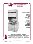
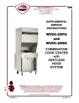
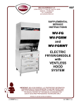
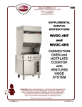
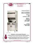
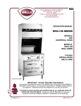
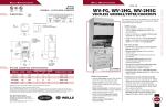
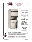
1
501
WELLS MANUFACTURING COMPANY
2 ERIK CIRCLE, P. O. Box 280
Verdi, NV 89439
telephone: 888-492-2782
fax: 888-492-2783
www.wellsbloomfield.com
SUPPLEMENTAL
SERVICE
INSTRUCTIONS
VCS2000
UNIVERSAL
HOOD
VENTLESS
COOK
SYSTEM
IMPORTANT: WELLS MANUFACTURING PROPRIETARY INFORMATION.
DISSEMINATION OF THIS INFORMATION TO ANYONE OTHER THAN
WELLS AUTHORIZED SERVICE AGENTS IS STRICTLY PROHIBITED.
TECHNICAL CONTENT OF THIS MANUAL IS DESIGNED FOR
USE BY QUALIFIED PROFESSIONAL TECHNICIANS ONLY.
PRINTED IN UNITED STATES OF AMERICA
p/n 503433 Rev. B
ECN-13117
S501
060724
cps
PRECAUTIONS AND GENERAL INFORMATION
WARNING:
Risk of
personal injury
Installation procedures
must be performed by a
qualified technician with
full knowledge of all
applicable electrical and
plumbing codes. Failure
can result in personal
injury and property
damage.
WARNING:
Electric
Shock hazard
All servicing requiring
access to non-insulated
electrical components
must be performed by a
qualified technician.
DO NOT open any
access panel which
requires the use of tools.
Failure to follow this
warning can result in severe electrical shock.
DO NOT connect or
energize this appliance
until all installation
instructions are read and
followed. Damage to the
appliance will result if
these instructions are not
followed.
This appliance is intended to prepare food for human consumption.
No other use is recommended or authorized by the manufacturer or its
agents.
Operators of this appliance must be familiar with the appliance use,
limitations and associated restrictions. Operating instructions must be
read and understood by all persons using or installing this appliance.
Cleanliness of this appliance is essential to good sanitation. Read and
follow all included cleaning instructions and schedules to ensure the
safety of the food product.
Disconnect this appliance from electrical power before performing any
maintenance or servicing.
DO NOT splash or pour water on, in or over any controls, control
panel or wiring.
The technical content of this manual, including any wiring diagrams,
schematics, parts breakdown illustrations and/or adjustment
procedures, is intended for use by qualified technical personnel.
Any procedure which requires the use of tools must be performed by a
qualified technician.
This appliance is made in the USA. Unless otherwise noted, this
appliance has American sizes on all hardware.
GENERAL DIMENSIONS:
Wide
Deep
High
30-3/8”
35-1/16”
77-3/16”
IMPORTANT INSTALLATION NOTE:
6” clearance is required from back and sides of the appliance to any
combustible or non-combustible surface.
xi
501 503433 SvcManual VCS2000 Universal Hood
CAUTION:
Risk of
Damage
This appliance is intended for use in commercial establishments
only.
TABLE OF CONTENTS
Precautions & General Information …………………………… xi
Electrical Specifications ..……………………………………….. 2
Features & Operating Controls …………………………………. 4
Hood Operation …………………………………………...……… 6
Troubleshooting Suggestions …………………………………… 7
Exploded Views & Parts Lists ………………………………….. 8
Material Safety Data Sheet—Ansulex Low Ph ……….……… 14
Wiring Diagram ……………………………………………..…… 16
INTRODUCTION
This manual contains information needed to properly service and repair the hood section of VCS200
Ventless Cook System equipment.
This manual applies to the following Wells Manufacturing models:
501 503433 SvcManual VCS2000 Universal Hood
WV-2HG
WV-2HSG
WV-4HC
WV-4HF
WV-4HS
WVF-886
WV-FG
WVG-136
WVOC-2HFG
WVOC-2HSG
WVOC-4HC
WVOC-4HF
WVOC-4HS
WVOC-G136
WV-2HGRW
WV-2HSGRW
WV-4HCRW
WV-4HFRW
WV-4HSRW
WVF-886RW
WV-FGRW
WVG-136RW
For installation, operation and maintenance instructions, refer to the Operation Manual for the specific
model.
1
ELECTRICAL SPEC IFICATIONS
MODEL
WV-2HG
WV-2HGRW
ROLL
WARMER
AMPS 3ø
VOLTS
WATTS
AMPS 1ø
L1
L2
L3
208
8,000
16
32
23
39
240
9,900
18
35
24
41
208
8,675
19
32
26
42
240
10,800
21
35
27
45
208
8,900
21
35
24
43
240
11,100
23
38
24
46
208
9,575
23
35
26
46
240
12,000
26
38
27
50
208
7,800
19
18
33
36
240
10,300
22
21
37
43
208
8,500
23
22
36
40
240
11,300
26
21
41
47
208
6,300
16
15
26
30
240
8,300
18
17
30
35
208
7,000
19
15
30
34
240
9,200
22
17
34
38
208
8,100
20
19
34
39
240
10,700
23
22
39
45
208
8,800
23
19
37
42
240
11,600
27
22
43
48
208
12,000
33
32
33
58
240
12,000
29
28
29
50
208
12,720
37
33
37
58
240
12,720
29
28
29
50
208
10,750
30
43
24
52
240
11,650
26
40
24
49
208
11,425
32
43
26
55
240
12,550
28
40
27
52
POWER SUPPLY
CORD
NO
YES
NEMA 15-60P
WV-2HSG
WV-2HSGRW
WV-4HC
WV-4HCRW
WV-4HF
NO
YES
NO
YES
NO
NEMA 15-60P
WV-4HFRW
WV-4HS
WVF-886
NO
YES
NO
NEMA 15-60P
WVF-886RW
WV-FG
YES
NO
NEMA 15-60P
WV-FGRW
YES
2
501 503433 SvcManual VCS2000 Universal Hood
WV-4HSRW
YES
ELECTRICAL SPEC IFICATIONS (continued)
MODEL
WVG-136
ROLL
WARMER
AMPS 3ø
VOLTS
WATTS
AMPS 1ø
L1
L2
L3
208
7,300
17
29
17
35
240
9,500
20
33
20
40
208
7,900
20
28
20
38
240
10,400
24
33
24
43
208
12800
37
36
33
62
240
15500
39
37
36
65
208
13700
41
38
35
66
240
16700
44
39
38
70
208
13000
39
37
32
63
240
16100
40
39
37
67
208
11500
35
34
26
55
240
14100
36
35
30
59
208
13300
39
38
34
64
240
16500
41
40
39
69
208
12,200
37
28
37
59
240
15,000
38
33
38
63
POWER SUPPLY
CORD
NO
NEMA 15-60P
WVG-136RW
WVOC-2HFG
YES
NO
NEMA 15-60P
WVOC-2HSG
WVOC-4HC
WVOC-4HF
WVOC-4HS
NO
NO
NEMA 15-60P
NO
NO
NEMA 15-60P
501 503433 SvcManual VCS2000 Universal Hood
WVOC-G136
NO
3
FEATURES & OPERATING CONTROLS
Factory-wired for griddle connection only.
B. COOKING APPLIANCE FUSES
Fuse protection for fryer circuits. Use 10 Amp Type G fuse only.
8. ADJUSTABLE (FRONT) LEG
Allows the unit to be leveled.
9. RIGID (REAR) CASTER
Allows the unit to be easily positioned by lifting the front of the unit
slightly. For full mobility, order front caster kit# 22650.
12. LOWER REAR ACCESS
IMPORTANT: If a remote pull station is installed, both rear casters (9) must be replaced with legs
(rear leg kit# 22649) to deter moving the unit. MOVING AN APPLIANCE WITH A REMOTE PULL
STATION WILL DISCHARGE THE FIRE SUPPRESSION SYSTEM.
16. GREASE BAFFLE
18. PRE-FILTER ASSEMBLY
19. HEPA/CHARCOAL FILTER
PACK
Allows access to Ansul® fire suppression automan components
Access to appliance power contactor (41).
Access by QUALIFIED ELECTRICIAN OR LICENSED ANSUL®
SERVICE DISTRIBUTOR ONLY.
Extracts and drains most grease and moisture from the air flow.
4
501 503433 SvcManual VCS2000 Universal Hood
A. POWER CONNECTION BOX
FEATURES & OPERATING CONTROLS (continued)
22. GREASE CUP
Collects grease/moisture drained from grease baffle (16).
27. UPPER REAR ACCESS PANEL
Allows rear access to pre-installed fusible links (a12).
28. VENTILATOR EXHAUST DUCT
Exit point for ventilator air flow on left rear top of unit.
29. TOP ACCESS PANEL
Allows access to controls, wiring diagram and ventilator fan (56).
38. POWER CORD AND PLUG
3ø with ground 60 Amp, NEMA 15-60P plug.
40. ROLL WARMER POWER
CONTACTOR
Energizes roll warmer section (when installed).
41. APPLIANCE POWER
CONTACTOR
Energizes cooking appliance only while ventilator section is sensed
as operational (all filters must be in position).
42. BUILDING FIRE ALARM
RELAY SYSTEM
Energized by Ansul® system discharge; for connection to building
fire alarm system.
44. EXTERNAL INTERLOCK
CONNECTION
For use with customer supplied hood power safety shut-down
or customer supplied facilities fire panel. See wiring schematic.
50. VACUUM SWITCHES (4)
Detects operation of ventilator and filters.
53. INTERLOCK SWITCHES
Detect presence of filter pack (18) and grease baffle (16).
Both filter pack switch and grease baffle switch must be made for
unit to operate.
56. VENTILATOR FAN
Provides air movement for ventilation and provides primary vacuum
for vacuum detection system.
60. SPACER
Maintains required 6” clearance to adjacent surfaces.
501 503433 SvcManual VCS2000 Universal Hood
NOTE: Fire suppression system and all associated components must be serviced only by an authorized
Ansul® Distributor. All setup, charging, repair and/or adjustment of the fire suppression system
must be performed by an Authorized Ansul® Distributor ONLY.
Operating this appliance without the Ansul® system functioning and certified will void the
warranty. Operator assumes all liability for fire-related injury and damage in the event any safety
feature is defeated and the unit is operated without a fully functional fire suppression system.
a6. FIRE SUPPRESSION AGENT
Pressurized container for fire suppression media. Ansul Low pH™
TANK (1.5 gal.) is the only agent authorized for use in this system.
a10. MANUAL PULL STATION
Provides a means of manual activation of the fire suppression
system. PULL ONLY IN CASE OF FIRE!
a12. UPPER FUSIBLE LINK
(PRE-INSTALLED)
Will melt, initiating a discharge of fire suppression system in the
event of temperature over 165ºF (fryer) or 212ºF (griddle).
a15. FIRE SUPPRESSION
DISCHARGE NOZZLES
Controls dispersion of fire suppression media in the event of a
discharge. Ansul® p/n 1W (plenum) and 290 (cooking appliance).
a30. SUPPRESSION AGENT
PROPELLANT BOTTLE
Used to propel suppression agent when system is activated.
Must be Ansul® propellant for R-102™ system.
a31. FIRE SUPPRESSION
CONTROL (AUTOMAN™)
STATUS INDICATOR
(COCKED - FIRED)
Controls discharge of fire suppression media. Displays status
of fire suppression system. If FIRED, a buzzer will sound
continuously.
5
HOOD OPERATION
WARNING: FIRE AND HEALTH HAZARDS
DO NOT bypass or attempt to bypass the filter placement interlocks. Operating the appliance
without filters properly in place will compromise the fire protection and air filtration capabilities of
this unit. Serious personal injury and/or substantial property damage may result.
NOTICE: Operating without all
filters properly in place, and/or
operating with filter placement
interlocks defeated will void the
manufacturer’s warranty.
Energizes the ventilator section. When all three filters are sensed as
being in their proper position, and sufficient airflow is proven, the
cooking appliance contactor (41) is energized.
46. INDICATOR LIGHT (GREEN)
VENTILATOR POWER ON
When lit, indicates that electrical power is available, and that the
power switch (45) is turned ON.
47a. INDICATOR LIGHT (AMBER)
CHECK FILTERS
When lit, indicates that one (or more) of the three filters is not in its
proper position, or that an interlock switch (53) is out of adjustment.
47b. INDICATOR LIGHT (AMBER)
REPLACE PREFILTER
When lit, indicates that the pre-filter is approaching the end of its
service life.
ALWAYS HAVE A SPARE PRE-FILTER ON HAND FOR
REPLACEMENT.
47c. INDICATOR LIGHT (AMBER)
REPLACE FILTER PACK
When lit, indicates that the filter pack is approaching the end of its service life.
REPLACE FILTER PACK PROMPTLY!
48.
Note: Power to the cooking appliance will be de-energized whenever
this RED “SERVICE REQUIRED” indicator light is lit. When lit, the air
flow is insufficient to meet appliance vapor capture levels
requirements. Indicates that either the pre-filter or the filter pack is
individually clogged (the individual indicator light may be lit), or that
the the airflow drop across both filters is critical. As a cost saving
measure, always change a dirty pre-filter first (when lights 47b &
47c are not lit, and red light 48 is on).
INDICATOR LIGHT (RED)
SERVICE REQUIRED
OPERATIONAL NOTES: REPLACE PREFILTER and REPLACE FILTER PACK indicator lights provide a
timely warning that a system shut-down is imminent. The actual time between the indicator light coming on
and the loss of cooking appliance power will depend upon the cooking conditions. Anytime a dirty PREFILTER is replaced, the system airflow will increase. If the condition of the FILTER PACK is marginal, the
REPLACE FILTER PACK light could then come on. If this happens, a fresh FILTER PACK must be installed
within a reasonably short time. Loss of airflow through the old filter pack will soon cause a system shut-down
when the airflow falls below minimum vapor capture levels. KEEP A SPARE FILTER PACK ON HAND.
IMPORTANT: If you decide to “get the most” out of the old filter pack, and continue to use it until a system
shut-down happens, it is advisable to have a fresh filter pack readily at hand, and have someone available
who is capable of replacing it. Otherwise, you may experience an extended down time, with consequent
associated loss of business.
The manufacturer assumes no liability for loss of business due to a system shutdown caused by a
dirty pre-filter and/or filter pack (i.e. red SERVICE REQUIRED light is on), when the user fails to have
the proper replacement pre-filter and/or filter pack on hand.
IMPORTANT: NEVER wash the PREFILTER or FILTER PACK.
This will shut down the cooking appliance. (Red “SERVICE REQUIRED” will turn ON).
6
501 503433 SvcManual VCS2000 Universal Hood
45. POWER SWITCH
TROUBLESHOOTING SUGGESTIONS
SYMPTOM
Entire unit inoperative - no lights
glow and no buzzer sounds
POSSIBLE CAUSE
Unit unplugged.
Plug power cord into receptacle
Circuit breaker off or tripped
Reset circuit breaker
Damaged power cord
Replace power cord
Damaged power switch
Check switch. Replace as req’d.
Contactor not energized
Cooking appliance inoperative
“POWER” light on hood ON. Vent
fan working ok with no service
lights on.
Vent fan starts Ok but amber
“CHECK FILTERS” light stays ON
Hood is operating but “REPLACE
PREFILTER” light ON.
501 503433 SvcManual VCS2000 Universal Hood
“REPLACE PREFILTER” light
turns on some of the time.
SUGGESTED REMEDY
Open coil. Replace contactor
Damaged wiring. Repair as req’d.
Vacuum line to switch #4 restricted
Check for restriction in vacuum
line to switch.
Vacuum switch # 4 open or
defective
Check vacuum switch # 4.
Replace as req’d.
Vacuum tap on blower plugged
Clean vacuum tap
One or more filter interlock
switches are open (grease baffle
or filter pack)
Missing or un-seated filter assy.
Reseat filter or adjust interlock
switch.
Vacuum switch # 1 open or
defective
Be sure pre-filter is hooked in
position. Check for disconnected
vacuum line on vacuum switch or
at pick-up port.
Prefilter is at end of service life
Replace prefilter
Vacuum Switch # 1 defective
Replace vacuum switch # 1
Pre-filter frame not hooked in posi- Hook metal pre-filterframe at top
tion at top
to prevent air blowing around filter
Prefilter is nearing end of service
life
Replace prefilter.
Appliance newly installed and
Ansul® system not yet charged.
Check status of Ansul® system at
rear of unit, if fired, call Ansul®
Service Distributor for set-up.
Vent fan not operating and buzzer
is sounding.
Ansul® system has been set off by
overtemp condition or manual pull
station has been activated.
Check status of Ansul® system at
rear of unit, if fired, call Ansul®
Service Distributor for replacement of fire suppressant agent
and propellant. If fuse link has
been activated, it must be replaced prior to re-cocking Ansul®
system.
Vent fan not operating.
Grease baffle not installed
Install grease baffle.
Buzzer silent.
Green “POWER” light ON.
Amber “CHECK FILTER” light and Grease baffle interlock switch mis- Check interlock switch, adjust or
adjusted or bad
replace
red “SERVICE REQUIRED” light
ON.
7
EXPLODED VIEW - CABINET COMPONENTS
501 503433 SvcManual VCS2000 Universal Hood
8
PARTS LIST - CABINET COMPONENTS
501 503433 SvcManual VCS2000 Universal Hood
ITEM
DESCRIPTION
WELLS PART NO.
1
ASSEMBLY, DOOR LEFT (NOT FOR –RW UNITS)
502642
2
ASSEMBLY, DOOR RIGHT (NOT FOR –RW UNITS)
502646
3
DOOR HINGE, LEFT
4
DOOR HINGE, RIGHT
5
MAGNET, DOOR CATCH
6
BRACKET, DOOR MAGNET
8
ASSEMBLY, ADJUSTABLE LEG
9
CASTER, REAR
16
BAFFLE, GREASE FILTER (TYPE 3)
22684
17
CAGE, PRE-FILTER
22683
18
PREFILTER
22618
19
ASSEMBLY, FILTER PACK
22619
20
HOUSING, LIGHT SOCKET
505098
21
BULB, APPLIANCE 100W
505100
22
GLASS GLOBE, LIGHT BULB COVER
505099
23
GREASE CUP
504405
24
PANEL, APPLIANCE REAR
25
ASSEMBLY, HOOD CABINET
26
PANEL, BACK
27
PANEL, REAR ACCESS
28
EXHAUST DUCT
29
ASSEMBLY, BLOWER FIRE DAMPER (286ºF)
30
PANEL, TOP COVER
31
SEALANT, 1/4” x 30”
32
LABEL, CONTROL PANEL
33
BRACKET, VACUUM SWITCHES
34
COVER, INTERLOCK
35
ASSEMBLY, BAFFLE INTERLOCK BRACKET
36
GUIDE, FILTER PACK
37
BRACKET, FILTER PACK INTERLOCK
66
GUIDE, -RW DRAWERS (-RW UNITS ONLY)
67
GASKET, SILICONE 15-1/4”
68
GASKET, SILICONE 18-1/2”
A9
CONDUIT BOX, MANUAL PULL STATION
A10
ANSUL® MANUAL PULL STATION
VENDOR PART NO.
(provided for
reference only)
66502
22649 (REAR LEG OPT)
20804
(2 SWIVEL, 2 FIXED)
KFD350A
502782
Must be applied with UL recognized
silicone adhesive
502772
502773
501389
9
4835
EXPLODED VIEW - ELECTRICAL & VACUUM COMPONENTS
501 503433 SvcManual VCS2000 Universal Hood
10
PARTS LIST - ELECTRICAL & VACUUM COMPONENTS
501 503433 SvcManual VCS2000 Universal Hood
ITEM
DESCRIPTION
WELLS PART NO.
20
HOUSING, LIGHT SOCKET
505098
21
BULB, APPLIANCE 100W
505100
22
GLASS GLOBE, LIGHT BULB COVER
505099
37
STRAIN RELIEF 1-1/4”, APPLETON
504420
38
ASSEMBLY, POWER CORD (INCLUDES STRAIN RELIEF)
22682
40
RELAY, 208/240V (-RW ONLY), STANCOR
41
CONTACTOR, 50a 3ø 208/240V, FASCO
502789
42
RELAY, BUILDING FIRE ALARM, STANCOR
64514
43
LUG, GROUND SOLDERLESS 6-14 GA.
44
TERMINAL BLOCK, 2 POLE
45
SWITCH, POWER
46
LIGHT, INDICATOR, GREEN 240V
55697
47
LIGHT, INDICATOR AMBER 240V
50516
48
LIGHT, INDICATOR RED 240V
51157
49
SWITCH, VACUUM #1
502590
50
SWITCH, VACUUM #2
502591
51
BUZZER, 240V
64834
52
SWITCH, VACUUM #3
502592
53
SWITCH, FILTER INTERLOCK
500407
54
SWITCH, VACUUM #4
502593
55
FITTING, CONDUIT 1/2” STRAIGHT
57748
56
BLOWER ASSEMBLY, 240V
502584
57
ADAPTER, QUIL-SEAL 3/8”
58
NIPPLE, 1/4NPT x 2” GALV
59
ADAPTER, 3/8TUBE x 1/4MPT
60
TEE, NYLON
61
TUBING, .18” x 1.0” CLEAR VINYL
62
TUBING, .18” x 5.5” CLEAR VINYL
63
ASSY, VACUUM TUBING MANIFOLD
64
ELBOW, 90º 1/4COMP x 1/4MPT
VENDOR PART NO.
(provided for
reference only)
NEMA-15-60P
53068
8528-40
77285
502588
11
FIRE SUPPRESSION COMPONENTS
EXAMPLE OF AN ANSUL® INSTALLATION
NOTE: Number and layout of tubing, nozzles and fusible links in various VCS2000 appliances may vary.
501 503433 SvcManual VCS2000 Universal Hood
FOR USE BY AUTHORIZED ANSUL® SERVICE PERSONNEL ONLY
Refer to Ansul® part no. 418087-05 R-102 Restaurant Fire Suppression System Design, Installation,
Recharge and Maintenance Manual.
12
PARTS LIST - FIRE SUPPRESSION COMPONENTS
ITEM
DESCRIPTION
WELLS PART NO.
VENDOR PART NO.
(provided for
reference only)
67099
7032
A1
CARTRIDGE, LT-20-R ANSUL
A3
ADAPTER, QUICK-SEAL 3/8”
77284
A4
PULLEY, ELBOW
423250
A5
MOUNTING BRACKET, ANSUL RELEASE MECHANISM, R-102
79493
A6
TANK, ANSULEX 1.5 GAL.
429864
A9
BOX, MANUAL PULL STATION
A10
ASSEMBLY, REMOTE PULL STATION
A11
HOLDER, LINK TERMINAL
501389
4835
LINK, FUSIBLE 212ºF, TYPE B
503037
415740
LINK, FUSIBLE 165ºF, TYPE B
502583
415739
A12
A13
FLEX HOSE, 82-3/4”
A14
NOZZLE 290 (COOKING APPLIANCE)
419342
A15
NOZZLE 1W (PLENUM)
419336
A22
FUSE LINK HOLDER (SERIES DETECTOR)
417369
A23
HOLDER, LINK BRACKET
A27
HOLDER, LINK CENTER
A28
HOLDER, LINK CABLE
A29
CABLE, WIRE ROPE
A37
STRAP, ANSULEX TANK
A38
BRACKET, ANSULEX TANK MOUNTING
10-S0046-80.75
67399
79653
501 503433 SvcManual VCS2000 Universal Hood
NOT SHOWN
MICRO SWITCH (RELEASE MECHANISM)
67273
TERMINAL BLOCK, REMOTE ALARM
53068
ANSULEX® EXTINGUISHING AGENT 1.5 GAL
67469
423878
79694
ADAPTER, QUICK-SEAL 1/4”
78196
STOP SLEEVE
26317
OVAL SLEEVE
4596
13
MSDS - ANSULEX™ Low pH FIRE SUPPRESSION MEDIA
501 503433 SvcManual VCS2000 Universal Hood
14
501 503433 SvcManual VCS2000 Universal Hood
MSDS - ANSULEX™ Low pH FIRE SUPPRESSION MEDIA
15
WIRING DIAGRAM
501 503433 SvcManual VCS2000 Universal Hood
16
501 503433 SvcManual VCS2000 Universal Hood
NOTES
17
IMPORTANT: WELLS MANUFACTURING PROPRIETARY INFORMATION.
DISSEMINATION OF THIS INFORMATION TO ANYONE OTHER THAN
WELLS AUTHORIZED SERVICE AGENTS IS STRICTLY PROHIBITED.
TECHNICAL CONTENT OF THIS MANUAL IS DESIGNED FOR
USE BY QUALIFIED PROFESSIONAL TECHNICIANS ONLY.
Commercial Food Equipment Service Association
Wells Manufacturing proudly supports CFESA
Commercial Food Equipment Service Association
SERVICE TRAINING - QUALITY SERVICE
Genuine Parts
Protect - YOU - All - Ways
CUSTOMER SATISFACTION
WELLS
WELLS MANUFACTURING COMPANY - Division of CARRIER COMMERCIAL REFRIGERATION
2 ERIK CIRCLE, P. O. Box 280
Verdi, NV 89439
telephone: 888-492-2872
fax: 888-492-2783
www.wellsbloomfield.com
PRINTED IN UNITED STATES OF AMERICA