1
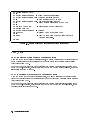
Agilent 4352B VCO/PLL Signal Analyzer
GPIB Programming Manual
SERIAL NUMBERS
This manual applies directly to instruments with serial number prex JP2KE.
For additional important information about serial
numbers, read \Serial Number" in Appendix A.
Agilent Part No. 04352-90077
Printed in JAPAN December 2001
Sixth Edition
Notice
The information contained in this document is subject to change without notice.
This document contains proprietary information that is protected by copyright. All rights are
reserved. No part of this document may be photocopied, reproduced, or translated to another
language without the prior written consent of the Agilent Technologies.
Agilent Technologies Japan, Ltd.
Component Test PGU-Kobe
1-3-2, Murotani, Nishi-ku, Kobe-shi,
Hyogo, 651-2241 Japan
R
MS-DOS
is a U.S. registered trademark of Microsoft Corporation.
c Copyright 1997, 1998, 1999, 2001 Agilent Technologies Japan, Ltd.
Manual Printing History
June 1997 : : : : : : : : : : : : : : : : : : : : : : : : : : : : : : : : : : : : : : : : : : : : First Edition (part number:
March 1998 : : : : : : : : : : : : : : : : : : : : : : : : : : : : : : : : : : : : : : : : Second Edition (part number:
July 1999 : : : : : : : : : : : : : : : : : : : : : : : : : : : : : : : : : : : : : : : : : : : : Third Edition (part number:
December 1999 : : : : : : : : : : : : : : : : : : : : : : : : : : : : : : : : : : : : Fourth Edition (part number:
January 2001 : : : : : : : : : : : : : : : : : : : : : : : : : : : : : : : : : : : : : : : : Fifth Edition (part number:
December 2001 : : : : : : : : : : : : : : : : : : : : : : : : : : : : : : : : : : : : : : Sixth Edition (part number:
04352-90047)
04352-90057)
04352-90067)
04352-90067)
04352-90067)
04352-90077)
iii
Symbols
General denitions of symbols used on equipment or in manuals:
Warning denotes a hazard. It calls attention to a procedure, practice, condition
or the like, which, if not correctly performed or adhered to, could result in
injury or death to personnel.
Caution denotes a hazard. It calls attention to a procedure, practice, condition
or the like, which, if not correctly performed or adhered to, could result
damage to or destruction of part or all of the product.
Note denotes important information. It calls attention to a procedure, practice,
condition or the like, which is essential to highlight.
CONTROLLER denotes information for a programmer using an external
computer as the system controller.
iBASIC denotes information for a programmer using an analyzer with HP
instrument BASIC as the system controller.
iv
Typeface Conventions
Bold
Italics
Computer
4HARDKEYS5
NNNNNNNNNNNNNNNNNNNNNNNNNN
SOFTKEYS
Boldface type is used when a term is dened. For example: icons are
symbols.
Italic type is used for emphasis and for titles of manuals and other
publications.
Italic type is also used for keyboard entries when a name or a variable
must be typed in place of the words in italics. For example: copy
lename means to type the word copy, to type a space, and then to
type the name of a le such as file1.
Computer font is used for on-screen prompts and messages.
Labeled keys on the instrument front panel are enclosed in 4 5.
Softkeys located to the right of the LCD are enclosed in .
NNNNN
How to Use This Manual
This manual provides an introduction to writing BASIC programs for the 4352B VCO/PLL Signal
Analyzer. To reduce the time required for you to learn how to write programs for the analyzer,
the examples shown in this guide are supplied on sample disks. You can perform each example
sequentially or you can select the examples that apply to your immediate needs and learn those
techniques . Use the table of contents and the index to quickly locate these examples. Also,
depending upon your experience in writing BASIC programs using GPIB commands, you may
want to do one of the following:
1. If you are an experienced programmer and have programmed GPIB systems before, you can
scan the examples in this guide to nd out how the analyzer can be used in your system.
If you have never programmed an instrument similar to the analyzer, you can start at the
beginning and do the examples that apply to your application.
2. If you are an experienced programmer, but do not have any knowledge of GPIB commands,
review some examples to decide where you need help. See the GPIB Command Reference
for additional information on GPIB commands.
3. If you are not an experienced programmer and you do not have any knowledge of GPIB
commands, see the GPIB Command Reference for a list of the documentation that you will
need to review before using this guide.
4. Refer to \Documentation Map" on the following page for HP instrument BASIC and the
other manuals.
v
Documentation Map
The following manuals are available for the analyzer:
Function Reference
The Function Reference describes all functions accessed from the front panel keys and
softkeys. It also provides information on options and accessories available, specications,
system performance, and conceptual information about the analyzer's features
GPIB Programming Manual
The GPIB Programming Manual describes basic programming methods when remotely
controlling the analyzer using the GPIB. It also contains information on the usage of all
GPIB commands, the status report mechanism, and the data transfer format.
Manual Supplement for HP instrument BASIC Users Handbook
This supplement describes how HP instrument BASIC works with the analyzer.
HP instrument BASIC Users Handbook
The HP instrument BASIC Users Handbook introduces you to the HP instrument BASIC
programming language, provides some helpful hints on getting the most use from it, and
provides a general programming reference. It is divided into three books, HP instrument
BASIC Programming Techniques , HP instrument BASIC Interface Techniques , and HP
instrument BASIC Language Reference.
43521A Operation Manual
This manual provides information on how to use the 43521ADown Converter Unit as
well as the features available with it. See also the 4352B Function Reference for how to
use the 43521A.
vi
Precautions
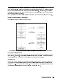
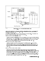
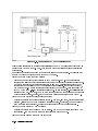
Removing Unwanted Components from Signal
The presence of undesired components picked up while the signal passes from the device to
the 4352B can result in reduced accuracy in measurement. When connecting a device to the
4352B, take one of the following measures to eliminate these components:
The 4352B employs the peak detection method to measure RF power. Therefore, the
presence of higher harmonics in the signal makes it extremely dicult to correctly measure
RF power. If such components may be contained in the signal, insert a low-pass lter into the
RF output terminal of the device to eliminate them.
The output impedance of the DC power and control voltage output terminals at RF can aect
output frequency characteristics (particularly, frequency or RF power) of the device. If this
is possible, insert a low-pass lter (cuto frequency between 100 kHz and 1 MHz) into each
of the DC power and control voltage output terminals.
How to Avoid Programming Errors When Using PRINT and USING
Statements Together
The message \Numeric image field too small" may appear if you execute the USING
statement included in the PRINT statement. This occurs frequently when an abnormal result is
obtained because the target value for the PRINT statement is outside the range specied by the
USING statement image.
You can avoid this problem by the following:
Not using the USING statement,
Checking the value before executing the PRINT statement and not executing the PRINT
statement if this value is outside the range specied with the USING statement image,
Changing the range specied by the USING statement image so that the value ts within the
range, or
Using the ON ERROR statement to handle errors.
vii
0
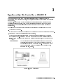
Using a Sample Program Disk
A sample program disk is furnished with 4352B. This disk contains the sample programs listed
in this manual.
Note
If you are going to use HP instrument BASIC, you must rst allocate the
4352B's display format to BASIC display by pressing 4Display5, MORE and
HALF INSTR HALF BASIC or ALL BASIC . See the HP instrument BASIC Users
Handbook Supplement for additional information.
NNNNNNNNNNNNNN
NNNNNNNNNNNNNNNNNNNNNNNNNNNNNNNNNNNNNNNNNNNNNNNNNNNNNNNNNNNNNNNNN
NNNNNNNNNNNNNNNNNNNNNNNNNNNNN
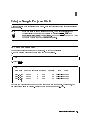
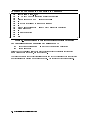
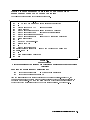
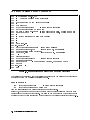
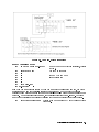
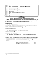
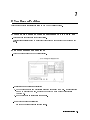
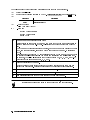
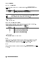
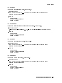
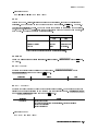
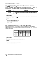
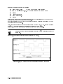
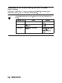
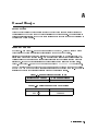
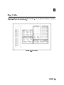
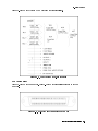
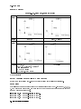
To Check the Files List
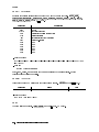
The sample programs are saved in ASCII format. To check the les list:
1. Put the program disk into the disk drive and type as follows.
d
a
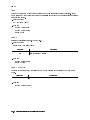
CAT
2. Press 4Return5.
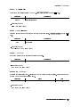
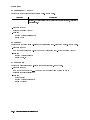
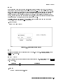
d
a
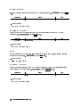
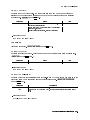
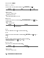
CAT
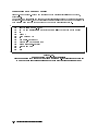
FILE NAME PRO TYPE REC/FILE BYTE/REC
FIG1_3.TXT
FIG2_2.TXT
FIG2_3.TXT
..
.
ASCII
ASCII
ASCII
6
6
6
256
256
256
ADDRESS
34
34
34
DATE
TIME
29-May-96 11:00
29-May-96 11:00
29-May-96 11:00
Each le name represents the number of the gure shown in this manual. For example, the
sample program listed in Figure 4-2 is saved with the le name FIG4_2.TXT.
Using a Sample Program Disk 0-1
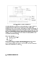
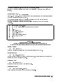
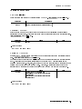
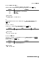
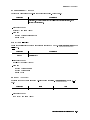
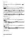
To Get a Program
To get the program use the GET command. For example, to get the sample program FIG4_2:
1. Type as follows:
d
GET "FIG4_2.TXT"
2. Press 4Return5.
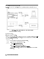
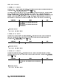
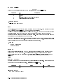
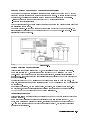
Screen Setup for Sample Program Execution
The statements INPUT and PRINT used in the sample programs are valid only when the BASIC
display is selected. Therefore, you must perform the following setups before you execute a
sample program. This will enable you to see the operation of the program and the status of the
instrument at the same time.
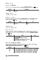
To use HP instrument BASIC, press 4Display5, MORE and
ALLOCAT'N:HALF INSTR HALF BASIC .
NNNNNNNNNNNNNN
NNNNNNNNNNNNNNNNNNNNNNNNNNNNNNNNNNNNNNNNNNNNNNNNNNNNNNNNNNNNNNNNNNNNNNNNNNNNNNNNNNNNNNNNNNNNNNN
To use a computer as the system controller, execute the following commands.
OUTPUT @4352;"DISA HIHB"
The customer shall have the personal, non-transferable rights to use, copy, or modify
SAMPLE PROGRAMS in this manual for the Customer's internal operations. The customer
shall use the SAMPLE PROGRAMS solely and exclusively for their own purpose and shall not
license, lease, market, or distribute the SAMPLE PROGRAMS or modication of any part
thereof.
Agilent Technologies shall not be liable for the quality, performance, or behavior of the
SAMPLE PROGRAMS. Agilent Technologies especially disclaims that the operation of the
SAMPLE PROGRAMS shall be uninterrupted or error free. The SAMPLE PROGRAMS are
provided AS IS.
AGILENT TECHNOLOGIES DISCLAIMS THE IMPLIED WARRANTIES OF MERCHANTABILITY
AND FITNESS FOR A PARTICULAR PURPOSE.
Agilent Technologies shall not be liable for any infringement of any patent, trademark,
copyright, or other proprietary rights by the SAMPLE PROGRAMS or their use. Agilent
Technologies does not warrant that the SAMPLE PROGRAMS are free from infringements of
such rights of third parties. However, Agilent Technologies will not knowingly infringe or
deliver software that infringes the patent, trademark, copyright, or other proprietary right of
a third party.
0-2 Using a Sample Program Disk
a
Contents
0. Using a Sample Program Disk
To Check the Files List . . . . . . . . . . . . . . . . . . . . . . . . . . . .
To Get a Program . . . . . . . . . . . . . . . . . . . . . . . . . . . . . .
Screen Setup for Sample Program Execution . . . . . . . . . . . . . . . . .
0-1
0-2
0-2
1. Overview of GPIB Remote Control System
Required Equipment . . . . . . . . . . . . . .
To Prepare for GPIB Control . . . . . . . . . .
GPIB Commands Introduction . . . . . . . . .
To Execute an GPIB Command . . . . . . . . .
To Program a Basic Measurement . . . . . . . .
Set I/O Path . . . . . . . . . . . . . . . . .
Set Up the Measurement Parameters . . . . .
Connecting a Device . . . . . . . . . . . . .
Trigger a Measurement . . . . . . . . . . . .
Transfer Data . . . . . . . . . . . . . . . .
To Execute an GPIB Command with a Parameter
Query Commands . . . . . . . . . . . . . . .
.
.
.
.
.
.
.
.
.
.
.
.
.
.
.
.
.
.
.
.
.
.
.
.
.
.
.
.
.
.
.
.
.
.
.
.
.
.
.
.
.
.
.
.
.
.
.
.
.
.
.
.
.
.
.
.
.
.
.
.
.
.
.
.
.
.
.
.
.
.
.
.
.
.
.
.
.
.
.
.
.
.
.
.
.
.
.
.
.
.
.
.
.
.
.
.
.
.
.
.
.
.
.
.
.
.
.
.
.
.
.
.
.
.
.
.
.
.
.
.
.
.
.
.
.
.
.
.
.
.
.
.
.
.
.
.
.
.
.
.
.
.
.
.
.
.
.
.
.
.
.
.
.
.
.
.
.
.
.
.
.
.
.
.
.
.
.
.
.
.
.
.
.
.
.
.
.
.
.
.
1-1
1-2
1-4
1-4
1-5
1-7
1-7
1-7
1-7
1-7
1-8
1-8
2. Triggering 4352B
To Measure Continuously . . . . . . . . . . .
Set Trigger Source . . . . . . . . . . . . .
Start Continuous Measurement Sweep . . .
Single measurement . . . . . . . . . . . . .
To Trigger a Measurement From the Controller
Set Trigger Source . . . . . . . . . . . . .
Trigger a Measurement . . . . . . . . . . .
Set Trigger Source . . . . . . . . . . . . .
Trigger a Measurement . . . . . . . . . . .
Using an External Trigger . . . . . . . . . .
Selecting Trigger Source . . . . . . . . . .
Measurement Trigger . . . . . . . . . . .
.
.
.
.
.
.
.
.
.
.
.
.
.
.
.
.
.
.
.
.
.
.
.
.
.
.
.
.
.
.
.
.
.
.
.
.
.
.
.
.
.
.
.
.
.
.
.
.
.
.
.
.
.
.
.
.
.
.
.
.
.
.
.
.
.
.
.
.
.
.
.
.
.
.
.
.
.
.
.
.
.
.
.
.
.
.
.
.
.
.
.
.
.
.
.
.
.
.
.
.
.
.
.
.
.
.
.
.
.
.
.
.
.
.
.
.
.
.
.
.
.
.
.
.
.
.
.
.
.
.
.
.
.
.
.
.
.
.
.
.
.
.
.
.
.
.
.
.
.
.
.
.
.
.
.
.
.
.
.
.
.
.
.
.
.
.
.
.
.
.
.
.
.
.
.
.
.
.
.
.
2-3
2-3
2-3
2-3
2-4
2-4
2-4
2-5
2-5
2-5
2-5
2-5
.
.
.
.
.
.
.
.
.
.
.
.
3. Synchronizing the Controller with 4352B
To Wait For the Preceding Operation to Complete . . . . . . . . . . . . . . .
Let Controller Wait For Operation to Complete (OPC) . . . . . . . . . . . . .
Waiting for Measurement Completion When Triggering a Measurement From the
External Controller . . . . . . . . . . . . . . . . . . . . . . . . . . . .
Enabling the Measurement Completion Bit . . . . . . . . . . . . . . . . .
Enable SRQ Interrupt . . . . . . . . . . . . . . . . . . . . . . . . . . .
Wait Until Measurement Is Done . . . . . . . . . . . . . . . . . . . . . .
Generate SRQ . . . . . . . . . . . . . . . . . . . . . . . . . . . . . . .
To Report Command Error Occurrence . . . . . . . . . . . . . . . . . . . .
Enable Error Bit . . . . . . . . . . . . . . . . . . . . . . . . . . . . . .
Report Command Error . . . . . . . . . . . . . . . . . . . . . . . . . .
Output Error . . . . . . . . . . . . . . . . . . . . . . . . . . . . . . .
3-2
3-2
3-3
3-3
3-4
3-5
3-5
3-6
3-6
3-7
3-8
Contents-1
Return to Execute GPIB command . . . . . . . . . . . . . . . . . . . . .
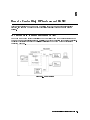
4. Loading Measurement Data into Controller
Data Formats . . . . . . . . . . . . . . . . . . . . . . . . . . . . . .
Loading Measurement Data in Tester Mode (When the 4352B's External Signal
Source Automatic Control Function Is Not Used) . . . . . . . . . . . . .
Transferring Data in ASCII Format . . . . . . . . . . . . . . . . . . . .
Setting Tester Mode . . . . . . . . . . . . . . . . . . . . . . . . . .
Setting Data Transfer Format . . . . . . . . . . . . . . . . . . . . . .
Loading Data . . . . . . . . . . . . . . . . . . . . . . . . . . . . .
Transferring Data in Binary Format . . . . . . . . . . . . . . . . . . . .
Setting Tester Mode . . . . . . . . . . . . . . . . . . . . . . . . . .
Setting Data Transfer Format . . . . . . . . . . . . . . . . . . . . . .
Loading Data . . . . . . . . . . . . . . . . . . . . . . . . . . . . .
Loading Measurement Data in Analyzer Mode (When External Signal Source
Automatic Control Function Is Not Used) . . . . . . . . . . . . . . . .
Transferring Data in ASCII Format . . . . . . . . . . . . . . . . . . . .
Specifying Array . . . . . . . . . . . . . . . . . . . . . . . . . . . .
Specifying Analyzer Mode . . . . . . . . . . . . . . . . . . . . . . .
Setting Data Transfer Format . . . . . . . . . . . . . . . . . . . . . .
Loading Data . . . . . . . . . . . . . . . . . . . . . . . . . . . . .
Transferring Data in Binary Format . . . . . . . . . . . . . . . . . . . .
Specifying Array . . . . . . . . . . . . . . . . . . . . . . . . . . . .
Specifying Analyzer Mode . . . . . . . . . . . . . . . . . . . . . . .
Setting Data Transfer Format . . . . . . . . . . . . . . . . . . . . . .
Loading Measurement Data in Analyzer Mode (When External Signal Source
Automatic Control Function Is Used) . . . . . . . . . . . . . . . . . . .
Transferring Data in ASCII Format . . . . . . . . . . . . . . . . . . . .
Passing Control . . . . . . . . . . . . . . . . . . . . . . . . . . . .
Specifying Array . . . . . . . . . . . . . . . . . . . . . . . . . . . .
Setting up GPIB . . . . . . . . . . . . . . . . . . . . . . . . . . . .
Transferring Data . . . . . . . . . . . . . . . . . . . . . . . . . . .
Specifying Array . . . . . . . . . . . . . . . . . . . . . . . . . . . .
Specifying Analyzer Mode . . . . . . . . . . . . . . . . . . . . . . .
Setting Data Transfer Format . . . . . . . . . . . . . . . . . . . . . .
Loading Data . . . . . . . . . . . . . . . . . . . . . . . . . . . . .
Transferring Data . . . . . . . . . . . . . . . . . . . . . . . . . . .
Transferring Data in Binary Format . . . . . . . . . . . . . . . . . . . .
Reading Data Using the Marker Search Function . . . . . . . . . . . . . . .
Searching for Maximum Value . . . . . . . . . . . . . . . . . . . . . .
Loading Data . . . . . . . . . . . . . . . . . . . . . . . . . . . . . .
5. Printing the 4352B's Display
To Print Analyzer Display . .
Printer Preparation . . . .
Execute Print . . . . . . .
To Observe Printing . . . . .
Contents-2
.
.
.
.
.
.
.
.
.
.
.
.
.
.
.
.
.
.
.
.
.
.
.
.
.
.
.
.
.
.
.
.
.
.
.
.
.
.
.
.
.
.
.
.
.
.
.
.
.
.
.
.
.
.
.
.
.
.
.
.
.
.
.
.
.
.
.
.
.
.
.
.
.
.
.
.
.
.
.
.
.
.
.
.
.
.
.
.
.
.
.
.
3-8
.
4-2
.
.
.
.
.
.
.
.
.
4-3
4-3
4-5
4-5
4-5
4-6
4-7
4-7
4-7
.
.
.
.
.
.
.
.
.
.
4-9
4-9
4-10
4-10
4-10
4-10
4-11
4-12
4-12
4-12
.
.
.
.
.
.
.
.
.
.
.
.
.
.
.
4-13
4-13
4-13
4-13
4-13
4-13
4-15
4-15
4-15
4-15
4-15
4-16
4-18
4-18
4-18
.
.
.
.
5-1
5-1
5-1
5-1
6. Remote Controlling HP instrument BASIC
To Control GPIB from HP instrument BASIC . . . . . . . . . . . . . . . .
To Execute an HP instrument BASIC Command From the External Controller.
To Run an HP instrument BASIC Program From the External Controller . . .
Open the HP instrument BASIC Editor . . . . . . . . . . . . . . . . .
Transfer the HP instrument BASIC Program . . . . . . . . . . . . . . .
Close the HP instrument BASIC Editor . . . . . . . . . . . . . . . . .
Run the HP instrument BASIC Program . . . . . . . . . . . . . . . . .
To Transfer Program to HP instrument BASIC . . . . . . . . . . . . . . .
Open the HP instrument BASIC Editor . . . . . . . . . . . . . . . . .
Transfer the Program . . . . . . . . . . . . . . . . . . . . . . . . .
Close the HP instrument BASIC Editor . . . . . . . . . . . . . . . . .
.
.
.
.
.
.
.
.
.
.
.
.
.
.
.
.
.
.
.
.
.
.
6-1
6-4
6-5
6-5
6-5
6-5
6-6
6-6
6-6
6-7
6-7
7. If You Have a Problem
If There Is No Response From an Instrument on the GPIB Bus
If an Error Message is Displayed . . . . . . . . . . . . . .
If You Cannot Get a File from the Disk . . . . . . . . . . .
If the GPIB Command Does Not Work . . . . . . . . . . . .
.
.
.
.
.
.
.
.
7-1
7-1
7-2
7-3
8. The Status Report System
OSPT, OSNT . . . . . . . . . . . . . . . . . . . . . . . . . . . . . . . . .
OSPT (Operation Status Positive Transition Filter) . . . . . . . . . . . . . .
OSNT (Operation Status Negative Transition Filter) . . . . . . . . . . . . .
8-6
8-6
8-6
9. Command Reference for Tester Mode
Command Reference . . . . . . . . . . . .
AFCtfOFFj0jONj1g . . . . . . . . . . .
AFCITERt<numeric> . . . . . . . . . .
AFCMAXVt<numeric> . . . . . . . . .
AFCMINVt<numeric> . . . . . . . . .
AFCSENSt<numeric> . . . . . . . . . .
AFCTARGt<numeric> . . . . . . . . .
AFCTOLt<numeric> . . . . . . . . . .
AVERtfOFFj0jONj1g . . . . . . . . . . .
AVERFACTt<numeric> . . . . . . . . .
AVERREST . . . . . . . . . . . . . . .
CNBWt<numeric> . . . . . . . . . . .
CNOFREQt<numeric> . . . . . . . . .
CONT . . . . . . . . . . . . . . . . . .
CTRLDLYt<numeric> . . . . . . . . . .
CTRLVCAL . . . . . . . . . . . . . . .
CTRLVCORRtfOFFj0jONj1g . . . . . . . .
DATGAINt<numeric> . . . . . . . . . .
DATMEM . . . . . . . . . . . . . . . .
DATOVALt<numeric> . . . . . . . . . .
DEFGO . . . . . . . . . . . . . . . . .
DEVCAL . . . . . . . . . . . . . . . .
DEVCALF?t<numeric> . . . . . . . . .
DEVCORRtfOFFj0jONj1g . . . . . . . . .
DEVRNGtfDV200KHZjDV20KHZjDV2KHZg
DHOLDtfOFFjMAXjMINg . . . . . . . .
DISPtfDATAjMEMOjDATMg . . . . . . .
DNCONVtfOFFj0jONj1g . . . . . . . . .
DTHPFtfFC50HZjFC300HZg . . . . . . .
DTLPFtfFC3KHZjFC15KHZjFC20KHZg . .
.
.
.
.
.
.
.
.
.
.
.
.
.
.
.
.
.
.
.
.
.
.
.
.
.
.
.
.
.
.
.
.
.
.
.
.
.
.
.
.
.
.
.
.
.
.
.
.
.
.
.
.
.
.
.
.
.
.
.
.
.
.
.
.
.
.
.
.
.
.
.
.
.
.
.
.
.
.
.
.
.
.
.
.
.
.
.
.
.
.
.
.
.
.
.
.
.
.
.
.
.
.
.
.
.
.
.
.
.
.
.
.
.
.
.
.
.
.
.
.
.
.
.
.
.
.
.
.
.
.
.
.
.
.
.
.
.
.
.
.
.
.
.
.
.
.
.
.
.
.
.
.
.
.
.
.
.
.
.
.
.
.
.
.
.
.
.
.
.
.
.
.
.
.
.
.
.
.
.
.
.
.
.
.
.
.
.
.
.
.
.
.
.
.
.
.
.
.
.
.
.
.
.
.
.
.
.
.
.
.
.
.
.
.
.
.
.
.
.
.
.
.
.
.
.
.
.
.
.
.
.
.
.
.
.
.
.
.
.
.
.
.
.
.
.
.
.
.
.
.
.
.
.
.
.
.
.
.
.
.
.
.
.
.
.
.
.
.
.
.
.
.
.
.
.
.
.
.
.
.
.
.
.
.
.
.
.
.
.
.
.
.
.
.
.
.
.
.
.
.
.
.
.
.
.
.
.
.
.
.
.
.
.
.
.
.
.
.
.
.
.
.
.
.
.
.
.
.
.
.
.
.
.
.
.
.
.
.
.
.
.
.
.
.
.
.
.
.
.
.
.
.
.
.
.
.
.
.
.
.
.
.
.
.
.
.
.
.
.
.
.
.
.
.
.
.
.
.
.
.
.
.
.
.
.
.
.
.
.
.
.
.
.
.
.
.
.
.
.
.
.
.
.
.
.
.
.
.
.
.
.
.
.
.
.
.
.
.
.
.
.
.
.
.
.
.
.
.
.
.
.
.
.
.
.
.
.
.
.
.
.
.
.
.
.
.
.
.
.
.
.
.
.
.
.
.
.
.
.
.
.
.
.
.
.
.
.
.
.
.
.
.
.
.
.
.
.
.
.
.
.
.
.
.
.
.
.
.
.
.
.
.
.
.
.
.
.
.
.
.
.
.
.
.
.
.
.
.
.
.
.
.
.
.
.
.
.
.
.
.
.
.
.
.
.
.
.
.
.
.
.
.
.
.
.
.
.
.
9-3
9-3
9-3
9-3
9-4
9-4
9-4
9-5
9-5
9-5
9-5
9-6
9-6
9-6
9-6
9-7
9-7
9-7
9-7
9-7
9-8
9-8
9-8
9-8
9-8
9-9
9-9
9-9
9-10
9-10
Contents-3
FBANDt<numeric> . . . . . . . . . .
FCOUNtfRES1KHZjRES64KHZg . . . .
HOLD . . . . . . . . . . . . . . . . .
INPUDATAt<numeric> . . . . . . . .
LCOMPtfOFFj0jONj1g . . . . . . . . .
LOAUTOtfOFFjONj0j1g . . . . . . . .
LOFREQ? . . . . . . . . . . . . . . .
LOSSt<numeric> . . . . . . . . . . .
LOSWTt<numeric> . . . . . . . . . .
MATHtfDATAjDPLMjDMNMjDDVMg . .
MAXVCTRLt<numeric> . . . . . . . .
MEAStfPOWEjFREQjCURRjFMDEVjCNg
MINVCTRLt<numeric> . . . . . . . .
MODAMPt<numeric> . . . . . . . . .
MODOtfOFFj0jONj1g . . . . . . . . .
NATTt<numeric> . . . . . . . . . . .
NOMFREQt<numeric> . . . . . . . .
OUTPDATA? . . . . . . . . . . . . . .
OUTPMEMO? . . . . . . . . . . . . .
PARMtfOFFj0jONj1g . . . . . . . . . .
PKCONVtfOFFj0jONj1g . . . . . . . .
POWUNITtfDBMjDBVjDBUVjWjVg . . .
PRES . . . . . . . . . . . . . . . . .
REST . . . . . . . . . . . . . . . . .
RFATTt<numeric> . . . . . . . . . .
SGCMDt<Character String>,<Divider>
SGTYPEtf1j2j3j4g . . . . . . . . . . .
SIGSRCH . . . . . . . . . . . . . . .
SING . . . . . . . . . . . . . . . . .
SLOPEt<numeric> . . . . . . . . . .
TRGPtfPOSjNEGg . . . . . . . . . . .
TRGStfINTjEXTjBUSjMANg . . . . . .
VA . . . . . . . . . . . . . . . . . .
VCTRLt<numeric> . . . . . . . . . .
VOUTtfOFFj0jONj1g . . . . . . . . . .
VPOWt<numeric> . . . . . . . . . .
.
.
.
.
.
.
.
.
.
.
.
.
.
.
.
.
.
.
.
.
.
.
.
.
.
.
.
.
.
.
.
.
.
.
.
.
.
.
.
.
.
.
.
.
.
.
.
.
.
.
.
.
.
.
.
.
.
.
.
.
.
.
.
.
.
.
.
.
.
.
.
.
.
.
.
.
.
.
.
.
.
.
.
.
.
.
.
.
.
.
.
.
.
.
.
.
.
.
.
.
.
.
.
.
.
.
.
.
.
.
.
.
.
.
.
.
.
.
.
.
.
.
.
.
.
.
.
.
.
.
.
.
.
.
.
.
.
.
.
.
.
.
.
.
.
.
.
.
.
.
.
.
.
.
.
.
.
.
.
.
.
.
.
.
.
.
.
.
.
.
.
.
.
.
.
.
.
.
.
.
.
.
.
.
.
.
.
.
.
.
.
.
.
.
.
.
.
.
.
.
.
.
.
.
.
.
.
.
.
.
.
.
.
.
.
.
.
.
.
.
.
.
.
.
.
.
.
.
.
.
.
.
.
.
.
.
.
.
.
.
.
.
.
.
.
.
.
.
.
.
.
.
.
.
.
.
.
.
.
.
.
.
.
.
.
.
.
.
.
.
.
.
.
.
.
.
.
.
.
.
.
.
.
.
.
.
.
.
.
.
.
.
.
.
.
.
.
.
.
.
.
.
.
.
.
.
.
.
.
.
.
.
.
.
.
.
.
.
.
.
.
.
.
.
.
.
.
.
.
.
.
.
.
.
.
.
.
.
.
.
.
.
.
.
.
.
.
.
.
.
.
.
.
.
.
.
.
.
.
.
.
.
.
.
.
.
.
.
.
.
.
.
.
.
.
.
.
.
.
.
.
.
.
.
.
.
.
.
.
.
.
.
.
.
.
.
.
.
.
.
.
.
.
.
.
.
.
.
.
.
.
.
.
.
.
.
.
.
.
.
.
.
.
.
.
.
.
.
.
.
.
.
.
.
.
.
.
.
.
.
.
.
.
.
.
.
.
.
.
.
.
.
.
.
.
.
.
.
.
.
.
.
.
.
.
.
.
.
.
.
.
.
.
.
.
.
.
.
.
.
.
.
.
.
.
.
.
.
.
.
.
.
.
.
.
.
.
.
.
.
.
.
.
.
.
.
.
.
.
.
.
.
.
.
.
.
.
.
.
.
.
.
.
.
.
.
.
.
.
.
.
.
.
.
.
.
.
.
.
.
.
.
.
.
.
.
.
.
.
.
.
.
.
.
.
.
.
.
.
.
.
.
.
.
.
.
.
.
.
.
.
.
.
.
.
.
.
.
.
.
.
.
.
.
.
.
.
.
.
.
.
.
.
.
.
.
.
.
.
.
.
.
.
.
.
.
.
.
.
.
.
.
.
.
.
.
.
.
.
.
.
.
.
.
.
.
.
.
.
.
.
.
.
.
.
.
.
.
.
.
.
.
.
.
.
.
.
.
9-10
9-11
9-11
9-11
9-11
9-12
9-12
9-12
9-12
9-13
9-13
9-13
9-14
9-14
9-14
9-14
9-15
9-15
9-15
9-15
9-16
9-16
9-16
9-16
9-17
9-17
9-17
9-18
9-18
9-18
9-18
9-19
9-19
9-19
9-19
9-20
10. Command Reference for Analyzer Mode
Command Reference . . . . . . . . . . .
AFCtfOFFj0jONj1g . . . . . . . . . .
AFCITERt<numeric> . . . . . . . . .
AFCMAXVt<numeric> . . . . . . . .
AFCMINVt<numeric> . . . . . . . .
AFCSENSt<numeric> . . . . . . . . .
AFCTARGt<numeric> . . . . . . . .
AFCTOLt<numeric> . . . . . . . . .
AUTO . . . . . . . . . . . . . . . . .
AVERtfOFFj0jONj1g . . . . . . . . . .
AVERFACTt<numeric> . . . . . . . .
AVERREST . . . . . . . . . . . . . .
BEEPFAILtfOFFj0jONj1g . . . . . . .
BWt<numeric> . . . . . . . . . . . .
CARRCENT . . . . . . . . . . . . . .
CARR2CENT . . . . . . . . . . . . .
CARR3CENT . . . . . . . . . . . . .
.
.
.
.
.
.
.
.
.
.
.
.
.
.
.
.
.
.
.
.
.
.
.
.
.
.
.
.
.
.
.
.
.
.
.
.
.
.
.
.
.
.
.
.
.
.
.
.
.
.
.
.
.
.
.
.
.
.
.
.
.
.
.
.
.
.
.
.
.
.
.
.
.
.
.
.
.
.
.
.
.
.
.
.
.
.
.
.
.
.
.
.
.
.
.
.
.
.
.
.
.
.
.
.
.
.
.
.
.
.
.
.
.
.
.
.
.
.
.
.
.
.
.
.
.
.
.
.
.
.
.
.
.
.
.
.
.
.
.
.
.
.
.
.
.
.
.
.
.
.
.
.
.
.
.
.
.
.
.
.
.
.
.
.
.
.
.
.
.
.
.
.
.
.
.
.
.
.
.
.
.
.
.
.
.
.
.
.
.
.
.
.
.
.
.
.
.
.
.
.
.
.
.
.
.
.
.
.
.
.
.
.
.
.
.
.
.
.
.
.
.
.
.
.
.
.
.
.
.
.
.
.
.
.
.
.
.
.
.
.
.
.
.
.
.
.
.
.
.
.
.
.
.
.
.
.
.
.
.
.
.
.
.
.
.
.
.
.
.
.
.
.
.
.
.
.
.
.
.
.
.
.
.
.
.
.
.
.
.
.
.
.
.
.
.
.
.
.
.
.
.
.
.
.
.
.
10-3
10-3
10-3
10-3
10-4
10-4
10-4
10-5
10-5
10-5
10-5
10-5
10-6
10-6
10-6
10-6
10-6
Contents-4
CARR? . . . . . . . . . . . . . . . . . . . . . . . . . . . . . . . . . .
CENTt<numeric> . . . . . . . . . . . . . . . . . . . . . . . . . . . .
CLRSMKRS . . . . . . . . . . . . . . . . . . . . . . . . . . . . . . . .
CNBWt<numeric> . . . . . . . . . . . . . . . . . . . . . . . . . . . .
CNPLLtfAUTOjWIDEg . . . . . . . . . . . . . . . . . . . . . . . . . . .
CONT . . . . . . . . . . . . . . . . . . . . . . . . . . . . . . . . . . .
CTRLDLYt<numeric> . . . . . . . . . . . . . . . . . . . . . . . . . . .
CTRLVCAL . . . . . . . . . . . . . . . . . . . . . . . . . . . . . . . .
CTRLVCORRtfOFFj0jONj1g . . . . . . . . . . . . . . . . . . . . . . . . .
DATGAINt<numeric> . . . . . . . . . . . . . . . . . . . . . . . . . . .
DATLIML . . . . . . . . . . . . . . . . . . . . . . . . . . . . . . . . .
DATLIMU . . . . . . . . . . . . . . . . . . . . . . . . . . . . . . . . .
DATMEM . . . . . . . . . . . . . . . . . . . . . . . . . . . . . . . . .
DATOVALt<numeric> . . . . . . . . . . . . . . . . . . . . . . . . . . .
DEFGO . . . . . . . . . . . . . . . . . . . . . . . . . . . . . . . . . .
DETtfPOSjNEGjSAMg . . . . . . . . . . . . . . . . . . . . . . . . . . .
DHOLDtfOFFjMAXjMINg . . . . . . . . . . . . . . . . . . . . . . . . .
DISPtfDATAjMEMOjDATMg . . . . . . . . . . . . . . . . . . . . . . . .
DMKRtfONjFIXjTRACjOFFg . . . . . . . . . . . . . . . . . . . . . . . .
DMKRPRMt<numeric> . . . . . . . . . . . . . . . . . . . . . . . . . .
DNCONVtfOFFj0jONj1g . . . . . . . . . . . . . . . . . . . . . . . . . .
DMKRVALt<numeric> . . . . . . . . . . . . . . . . . . . . . . . . . .
EXDATLIML . . . . . . . . . . . . . . . . . . . . . . . . . . . . . . . .
EXDATLIMU . . . . . . . . . . . . . . . . . . . . . . . . . . . . . . . .
FBANDt<numeric> . . . . . . . . . . . . . . . . . . . . . . . . . . . .
FCOUNtfRES1KHZjRES64KHZg . . . . . . . . . . . . . . . . . . . . . .
HOLD . . . . . . . . . . . . . . . . . . . . . . . . . . . . . . . . . . .
INPUDATAt<numeric(1)>,<numeric(2)>, . . . <numeric(n)> . . . . . . . .
INPULIMLt<numeric(1)>,<numeric(2)>, . . . <numeric(n)> . . . . . . . . .
INPULIMUt<numeric(1)>,<numeric(2)>, . . . <numeric(n)> . . . . . . . .
INTGNOIS? . . . . . . . . . . . . . . . . . . . . . . . . . . . . . . . .
LCOMPtfOFFj0jONj1g . . . . . . . . . . . . . . . . . . . . . . . . . . .
LIMCLEL . . . . . . . . . . . . . . . . . . . . . . . . . . . . . . . . .
LIMILINEtfOFFj0jONj1g . . . . . . . . . . . . . . . . . . . . . . . . . .
LIMISTAT? . . . . . . . . . . . . . . . . . . . . . . . . . . . . . . . .
LIMITESTtfOFFj0jONj1g . . . . . . . . . . . . . . . . . . . . . . . . . .
LIMSECTt<Param1>, <UpLmt1>, <LowLmt1>, <Param2>, <UpLmt2>,
<LowLmt2> . . . . . . . . . . . . . . . . . . . . . . . . . . . . . .
LIMSECTNt<ParamN1>, <UpLmt1>, <LowLmt1>, <ParamN2>, <UpLmt2>,
<LowLmt2> . . . . . . . . . . . . . . . . . . . . . . . . . . . . . .
LOAUTOtfOFFj0jONj1g . . . . . . . . . . . . . . . . . . . . . . . . . .
LOFREQ? . . . . . . . . . . . . . . . . . . . . . . . . . . . . . . . . .
LOSSt<numeric> . . . . . . . . . . . . . . . . . . . . . . . . . . . . .
LOSWTt<numeric> . . . . . . . . . . . . . . . . . . . . . . . . . . . .
MAXVCTRLt<numeric> . . . . . . . . . . . . . . . . . . . . . . . . . .
MEAINOIStfOFFj0jONj1g . . . . . . . . . . . . . . . . . . . . . . . . .
MEAStfPOWEjFREQjNOISjTRANjSPECg . . . . . . . . . . . . . . . . . .
MINVCTRLt<numeric> . . . . . . . . . . . . . . . . . . . . . . . . . .
MKRtfOFFj0jONj1g . . . . . . . . . . . . . . . . . . . . . . . . . . . .
MKRCENT . . . . . . . . . . . . . . . . . . . . . . . . . . . . . . . .
MKRCONTtfOFFj0jONj1g . . . . . . . . . . . . . . . . . . . . . . . . .
MKRLtfOFFj0jONj1g . . . . . . . . . . . . . . . . . . . . . . . . . . . .
MKROtfDATAjMEMOg . . . . . . . . . . . . . . . . . . . . . . . . . . .
MKRPt<numeric> . . . . . . . . . . . . . . . . . . . . . . . . . . . .
MKRPRMt<numeric> . . . . . . . . . . . . . . . . . . . . . . . . . . .
10-6
10-7
10-7
10-7
10-7
10-8
10-8
10-8
10-8
10-8
10-9
10-9
10-9
10-9
10-9
10-9
10-10
10-10
10-10
10-11
10-11
10-11
10-11
10-12
10-12
10-12
10-13
10-13
10-13
10-13
10-13
10-14
10-14
10-14
10-14
10-15
10-15
10-15
10-16
10-16
10-16
10-16
10-17
10-17
10-17
10-18
10-18
10-18
10-18
10-19
10-19
10-19
10-19
Contents-5
MKRPRM? . . . . . . . . . . . . . . .
MKRREF . . . . . . . . . . . . . . .
MKRSTAR . . . . . . . . . . . . . . .
MKRSTOP . . . . . . . . . . . . . . .
MKRTHRE . . . . . . . . . . . . . .
MKRVAL? . . . . . . . . . . . . . . .
MKRVCTRL . . . . . . . . . . . . . .
MODAMPt<numeric> . . . . . . . . .
MODOtfOFFj0jONj1g . . . . . . . . .
NATTt<numeric> . . . . . . . . . . .
NOMFREQt<numeric> . . . . . . . .
OUTPDATA? . . . . . . . . . . . . . .
OUTPDATAP?t<Integer> . . . . . . .
OUTPDMKR? . . . . . . . . . . . . .
OUTPSMKRf1-4g? . . . . . . . . . . .
OUTPLIML? . . . . . . . . . . . . . .
OUTPLIMRES? . . . . . . . . . . . . .
OUTPLIMU? . . . . . . . . . . . . . .
OUTPMEMO? . . . . . . . . . . . . .
OUTPMEMOP?t<Integer> . . . . . . .
OUTPMKR? . . . . . . . . . . . . . .
OUTPSWPRM? . . . . . . . . . . . . .
OUTPSWPRMP?t<Integer> . . . . . .
PARStfOFFj0jONj1g . . . . . . . . . .
PKDLTYt<numeric> . . . . . . . . .
PKTHREtfOFFj0jONj1g . . . . . . . .
PKTHVALt<numeric> . . . . . . . . .
POINt<numeric> . . . . . . . . . . .
POWUNITtfDBMjDBVjDBUVjWjVg . . .
PRES . . . . . . . . . . . . . . . . .
PRSMKRS . . . . . . . . . . . . . . .
REFPt<Integer> . . . . . . . . . . .
REFVt<numeric> . . . . . . . . . . .
REST . . . . . . . . . . . . . . . . .
RFATTt<numeric> . . . . . . . . . .
SAVLIMtfOFFj0jONj1g . . . . . . . . .
SCACtfOFFj0jONj1g . . . . . . . . . .
SCAFtfDATAjMEMOg . . . . . . . . .
SCALt<numeric> . . . . . . . . . . .
SEAL . . . . . . . . . . . . . . . . .
SEAMtfPEAKjMAXjMINjTARGjOFFg . .
SEANPK . . . . . . . . . . . . . . .
SEANPKL . . . . . . . . . . . . . . .
SEANPKR . . . . . . . . . . . . . . .
SEAR . . . . . . . . . . . . . . . . .
SEARSTR . . . . . . . . . . . . . . .
SEARSTRL . . . . . . . . . . . . . .
SEARSTRR . . . . . . . . . . . . . .
SEATARGt<numeric> . . . . . . . . .
SENSAPERt<numeric> . . . . . . . .
SENSPOLtfPOSjNEGg . . . . . . . . .
SGCMDt<Character String>,<Divider>
SGTYPEtf1j2j3j4g . . . . . . . . . . .
SING . . . . . . . . . . . . . . . . .
SIGSRCH . . . . . . . . . . . . . . .
Contents-6
.
.
.
.
.
.
.
.
.
.
.
.
.
.
.
.
.
.
.
.
.
.
.
.
.
.
.
.
.
.
.
.
.
.
.
.
.
.
.
.
.
.
.
.
.
.
.
.
.
.
.
.
.
.
.
.
.
.
.
.
.
.
.
.
.
.
.
.
.
.
.
.
.
.
.
.
.
.
.
.
.
.
.
.
.
.
.
.
.
.
.
.
.
.
.
.
.
.
.
.
.
.
.
.
.
.
.
.
.
.
.
.
.
.
.
.
.
.
.
.
.
.
.
.
.
.
.
.
.
.
.
.
.
.
.
.
.
.
.
.
.
.
.
.
.
.
.
.
.
.
.
.
.
.
.
.
.
.
.
.
.
.
.
.
.
.
.
.
.
.
.
.
.
.
.
.
.
.
.
.
.
.
.
.
.
.
.
.
.
.
.
.
.
.
.
.
.
.
.
.
.
.
.
.
.
.
.
.
.
.
.
.
.
.
.
.
.
.
.
.
.
.
.
.
.
.
.
.
.
.
.
.
.
.
.
.
.
.
.
.
.
.
.
.
.
.
.
.
.
.
.
.
.
.
.
.
.
.
.
.
.
.
.
.
.
.
.
.
.
.
.
.
.
.
.
.
.
.
.
.
.
.
.
.
.
.
.
.
.
.
.
.
.
.
.
.
.
.
.
.
.
.
.
.
.
.
.
.
.
.
.
.
.
.
.
.
.
.
.
.
.
.
.
.
.
.
.
.
.
.
.
.
.
.
.
.
.
.
.
.
.
.
.
.
.
.
.
.
.
.
.
.
.
.
.
.
.
.
.
.
.
.
.
.
.
.
.
.
.
.
.
.
.
.
.
.
.
.
.
.
.
.
.
.
.
.
.
.
.
.
.
.
.
.
.
.
.
.
.
.
.
.
.
.
.
.
.
.
.
.
.
.
.
.
.
.
.
.
.
.
.
.
.
.
.
.
.
.
.
.
.
.
.
.
.
.
.
.
.
.
.
.
.
.
.
.
.
.
.
.
.
.
.
.
.
.
.
.
.
.
.
.
.
.
.
.
.
.
.
.
.
.
.
.
.
.
.
.
.
.
.
.
.
.
.
.
.
.
.
.
.
.
.
.
.
.
.
.
.
.
.
.
.
.
.
.
.
.
.
.
.
.
.
.
.
.
.
.
.
.
.
.
.
.
.
.
.
.
.
.
.
.
.
.
.
.
.
.
.
.
.
.
.
.
.
.
.
.
.
.
.
.
.
.
.
.
.
.
.
.
.
.
.
.
.
.
.
.
.
.
.
.
.
.
.
.
.
.
.
.
.
.
.
.
.
.
.
.
.
.
.
.
.
.
.
.
.
.
.
.
.
.
.
.
.
.
.
.
.
.
.
.
.
.
.
.
.
.
.
.
.
.
.
.
.
.
.
.
.
.
.
.
.
.
.
.
.
.
.
.
.
.
.
.
.
.
.
.
.
.
.
.
.
.
.
.
.
.
.
.
.
.
.
.
.
.
.
.
.
.
.
.
.
.
.
.
.
.
.
.
.
.
.
.
.
.
.
.
.
.
.
.
.
.
.
.
.
.
.
.
.
.
.
.
.
.
.
.
.
.
.
.
.
.
.
.
.
.
.
.
.
.
.
.
.
.
.
.
.
.
.
.
.
.
.
.
.
.
.
.
.
.
.
.
.
.
.
.
.
.
.
.
.
.
.
.
.
.
.
.
.
.
.
.
.
.
.
.
.
.
.
.
.
.
.
.
.
.
.
.
.
.
.
.
.
.
.
.
.
.
.
.
.
.
.
.
.
.
.
.
.
.
.
.
.
.
.
.
.
.
.
.
.
.
.
.
.
.
.
.
.
.
.
.
.
.
.
.
.
.
.
.
.
.
.
.
.
.
.
.
.
.
.
.
.
.
.
.
.
.
.
.
.
.
.
.
.
.
.
.
.
.
.
.
.
.
.
.
.
.
.
.
.
.
.
.
.
.
.
.
.
.
.
.
.
.
.
.
.
.
.
.
.
.
.
.
.
.
.
.
.
.
.
.
.
.
.
.
.
.
.
.
.
.
.
.
.
.
.
.
.
.
.
.
.
.
.
.
.
.
.
.
.
.
.
.
.
.
.
.
.
.
.
.
.
.
.
.
.
.
.
.
.
.
.
.
.
.
.
.
.
.
.
.
.
.
.
.
.
.
.
.
.
.
.
.
.
.
.
.
.
.
.
.
.
.
.
.
.
.
10-20
10-20
10-20
10-20
10-20
10-20
10-20
10-21
10-21
10-21
10-21
10-22
10-22
10-22
10-22
10-23
10-23
10-23
10-23
10-24
10-24
10-24
10-25
10-25
10-25
10-26
10-26
10-26
10-26
10-27
10-27
10-27
10-27
10-28
10-28
10-28
10-28
10-29
10-29
10-29
10-29
10-29
10-30
10-30
10-30
10-30
10-30
10-30
10-30
10-31
10-31
10-31
10-32
10-32
10-32
SLOPEt<numeric> . . . . . . . . .
SMKRf1-4gtfOFFj0jONj1g . . . . . .
SMKRPf1-4gt<numeric> . . . . . .
SMKRPf1-4g? . . . . . . . . . . . .
SMKRVALf1-4g? . . . . . . . . . . .
SPANt<numeric> . . . . . . . . . .
STARt<numeric> . . . . . . . . . .
STOPt<numeric> . . . . . . . . . .
SWETt<numeric> . . . . . . . . .
SWPTtfLOGFjLINFg . . . . . . . . .
TRACKtfOFFj0jONj1g . . . . . . . .
TRGOUTtfOFFj0jONj1g . . . . . . .
TRGPtfPOSjNEGg . . . . . . . . . .
TRGStfINTjEXTjBUSjMANjVALg . . .
TRGVALt<numeric> . . . . . . . .
TRMAXt<numeric> . . . . . . . . .
TRMINt<numeric> . . . . . . . . .
TRREFt<numeric> . . . . . . . . .
TRSPANtfTS2MHZjTS20MHZjTSMAXg
TRTARGt<numeric> . . . . . . . .
TRTPOSt<numeric> . . . . . . . . .
VBWt<numeric> . . . . . . . . . .
VCTRLt<numeric> . . . . . . . . .
VOUTtfOFFj0jONj1g . . . . . . . . .
VPOWt<numeric> . . . . . . . . .
VT . . . . . . . . . . . . . . . . .
.
.
.
.
.
.
.
.
.
.
.
.
.
.
.
.
.
.
.
.
.
.
.
.
.
.
.
.
.
.
.
.
.
.
.
.
.
.
.
.
.
.
.
.
.
.
.
.
.
.
.
.
.
.
.
.
.
.
.
.
.
.
.
.
.
.
.
.
.
.
.
.
.
.
.
.
.
.
.
.
.
.
.
.
.
.
.
.
.
.
.
.
.
.
.
.
.
.
.
.
.
.
.
.
.
.
.
.
.
.
.
.
.
.
.
.
.
.
.
.
.
.
.
.
.
.
.
.
.
.
.
.
.
.
.
.
.
.
.
.
.
.
.
.
.
.
.
.
.
.
.
.
.
.
.
.
.
.
.
.
.
.
.
.
.
.
.
.
.
.
.
.
.
.
.
.
.
.
.
.
.
.
.
.
.
.
.
.
.
.
.
.
.
.
.
.
.
.
.
.
.
.
.
.
.
.
.
.
.
.
.
.
.
.
.
.
.
.
.
.
.
.
.
.
.
.
.
.
.
.
.
.
.
.
.
.
.
.
.
.
.
.
.
.
.
.
.
.
.
.
.
.
.
.
.
.
.
.
.
.
.
.
.
.
.
.
.
.
.
.
.
.
.
.
.
.
.
.
.
.
.
.
.
.
.
.
.
.
.
.
.
.
.
.
.
.
.
.
.
.
.
.
.
.
.
.
.
.
.
.
.
.
.
.
.
.
.
.
.
.
.
.
.
.
.
.
.
.
.
.
.
.
.
.
.
.
.
.
.
.
.
.
.
.
.
.
.
.
.
.
.
.
.
.
.
.
.
.
.
.
.
.
.
.
.
.
.
.
.
.
.
.
.
.
.
.
.
.
.
.
.
.
.
.
.
.
.
.
.
.
.
.
.
.
.
.
.
.
.
.
.
.
.
.
.
.
.
.
.
.
.
.
.
.
.
.
.
.
.
.
.
.
.
.
.
.
.
.
.
.
.
.
.
.
.
.
.
.
.
.
.
.
.
.
.
.
.
.
.
.
.
.
.
.
.
.
.
.
.
.
.
.
.
.
.
.
.
.
.
.
.
.
.
.
.
.
.
.
.
.
.
.
.
.
.
.
.
.
.
.
.
.
.
.
10-32
10-33
10-33
10-33
10-33
10-33
10-34
10-34
10-34
10-35
10-35
10-35
10-35
10-36
10-36
10-36
10-36
10-37
10-37
10-37
10-38
10-38
10-39
10-39
10-39
10-39
11. Command Reference for Commonly Used Commands
Command Reference . . . . . . . . . . . . . . . . .
ADDRCONTt<numeric> . . . . . . . . . . . . . .
ADDRSGt<numeric> . . . . . . . . . . . . . . .
BACIt<numeric> . . . . . . . . . . . . . . . . .
BEEPDONEtfOFFj0jONj1g . . . . . . . . . . . . .
BEEPWARNtfOFFj0jONj1g . . . . . . . . . . . . .
BLIGHTtfOFFj0jONj1g . . . . . . . . . . . . . . .
CBRIt<numeric> . . . . . . . . . . . . . . . . .
CIN . . . . . . . . . . . . . . . . . . . . . . . .
CHADt<String> . . . . . . . . . . . . . . . . .
CLES . . . . . . . . . . . . . . . . . . . . . . .
CLOSE . . . . . . . . . . . . . . . . . . . . . .
COLOt<parameter> . . . . . . . . . . . . . . . .
COLORt<numeric> . . . . . . . . . . . . . . . .
COPA . . . . . . . . . . . . . . . . . . . . . . .
COPTtfOFFj0jONj1g . . . . . . . . . . . . . . . .
COUT . . . . . . . . . . . . . . . . . . . . . . .
CREDt<String> . . . . . . . . . . . . . . . . . .
CWD? . . . . . . . . . . . . . . . . . . . . . . .
DAYMYEAR . . . . . . . . . . . . . . . . . . . .
DEFC . . . . . . . . . . . . . . . . . . . . . . .
DFLT . . . . . . . . . . . . . . . . . . . . . . .
DIN . . . . . . . . . . . . . . . . . . . . . . . .
DISAtfALLIjHIHBjALLBjBASSg . . . . . . . . . .
DISFtfDOSjLIFg . . . . . . . . . . . . . . . . . .
DOUT . . . . . . . . . . . . . . . . . . . . . . .
DPIt<numeric> . . . . . . . . . . . . . . . . .
.
.
.
.
.
.
.
.
.
.
.
.
.
.
.
.
.
.
.
.
.
.
.
.
.
.
.
.
.
.
.
.
.
.
.
.
.
.
.
.
.
.
.
.
.
.
.
.
.
.
.
.
.
.
.
.
.
.
.
.
.
.
.
.
.
.
.
.
.
.
.
.
.
.
.
.
.
.
.
.
.
.
.
.
.
.
.
.
.
.
.
.
.
.
.
.
.
.
.
.
.
.
.
.
.
.
.
.
.
.
.
.
.
.
.
.
.
.
.
.
.
.
.
.
.
.
.
.
.
.
.
.
.
.
.
.
.
.
.
.
.
.
.
.
.
.
.
.
.
.
.
.
.
.
.
.
.
.
.
.
.
.
.
.
.
.
.
.
.
.
.
.
.
.
.
.
.
.
.
.
.
.
.
.
.
.
.
.
.
.
.
.
.
.
.
.
.
.
.
.
.
.
.
.
.
.
.
.
.
.
.
.
.
.
.
.
.
.
.
.
.
.
.
.
.
.
.
.
.
.
.
.
.
.
.
.
.
.
.
.
.
.
.
.
.
.
.
.
.
.
.
.
.
.
.
.
.
.
.
.
.
.
.
.
.
.
.
.
.
.
.
.
.
.
.
.
.
.
.
.
.
.
.
.
.
.
.
.
.
.
.
.
.
.
.
.
.
.
.
.
.
.
.
.
.
.
.
.
.
.
.
.
.
.
.
.
.
.
.
.
.
.
.
.
11-3
11-3
11-3
11-3
11-3
11-4
11-4
11-4
11-4
11-5
11-5
11-5
11-6
11-6
11-6
11-7
11-7
11-7
11-7
11-7
11-7
11-8
11-8
11-8
11-9
11-9
11-9
Contents-7
DSKEY . . . . . . . . . . . . . . . . . . . . . . . . . . . . .
ENKEY . . . . . . . . . . . . . . . . . . . . . . . . . . . . .
ESB? . . . . . . . . . . . . . . . . . . . . . . . . . . . . . .
ESNBt<numeric> . . . . . . . . . . . . . . . . . . . . . . . .
FILCt<character string 1>,<character string 2>,<character string
3>,<character string 4> . . . . . . . . . . . . . . . . . . .
FNAME?t<numeric> . . . . . . . . . . . . . . . . . . . . . .
FNUM? . . . . . . . . . . . . . . . . . . . . . . . . . . . . .
FORM2 . . . . . . . . . . . . . . . . . . . . . . . . . . . . .
FORM3 . . . . . . . . . . . . . . . . . . . . . . . . . . . . .
FORM4 . . . . . . . . . . . . . . . . . . . . . . . . . . . . .
FORM5 . . . . . . . . . . . . . . . . . . . . . . . . . . . . .
FORMFEEDtfOFFj0jONj1g . . . . . . . . . . . . . . . . . . . .
FSIZE?t<string> . . . . . . . . . . . . . . . . . . . . . . . .
INID . . . . . . . . . . . . . . . . . . . . . . . . . . . . . .
INP8IO? . . . . . . . . . . . . . . . . . . . . . . . . . . . . .
INPT? . . . . . . . . . . . . . . . . . . . . . . . . . . . . . .
INTEt<numeric> . . . . . . . . . . . . . . . . . . . . . . . .
KEYt<numeric> . . . . . . . . . . . . . . . . . . . . . . . .
LANDSCAPEtfOFFj0jONj1g . . . . . . . . . . . . . . . . . . .
LMARGt<numeric> . . . . . . . . . . . . . . . . . . . . . . .
MONDYEAR . . . . . . . . . . . . . . . . . . . . . . . . . . .
NEGL . . . . . . . . . . . . . . . . . . . . . . . . . . . . . .
NEXP . . . . . . . . . . . . . . . . . . . . . . . . . . . . . .
OPEP . . . . . . . . . . . . . . . . . . . . . . . . . . . . . .
OSEt<numeric> . . . . . . . . . . . . . . . . . . . . . . . .
OSER? . . . . . . . . . . . . . . . . . . . . . . . . . . . . .
OSNTt<numeric> . . . . . . . . . . . . . . . . . . . . . . . .
OSPTt<numeric> . . . . . . . . . . . . . . . . . . . . . . . .
OSR? . . . . . . . . . . . . . . . . . . . . . . . . . . . . . .
OUT1ENVH . . . . . . . . . . . . . . . . . . . . . . . . . . .
OUT1ENVL . . . . . . . . . . . . . . . . . . . . . . . . . . .
OUT1H . . . . . . . . . . . . . . . . . . . . . . . . . . . . .
OUT1L . . . . . . . . . . . . . . . . . . . . . . . . . . . . .
OUT2ENVH . . . . . . . . . . . . . . . . . . . . . . . . . . .
OUT2ENVL . . . . . . . . . . . . . . . . . . . . . . . . . . .
OUT2H . . . . . . . . . . . . . . . . . . . . . . . . . . . . .
OUT2L . . . . . . . . . . . . . . . . . . . . . . . . . . . . .
OUT8IOt<numeric> . . . . . . . . . . . . . . . . . . . . . . .
OUTAIOt<numeric> . . . . . . . . . . . . . . . . . . . . . .
OUTBIOt<numeric> . . . . . . . . . . . . . . . . . . . . . .
OUTCIOt<numeric> . . . . . . . . . . . . . . . . . . . . . .
OUTDIOt<numeric> . . . . . . . . . . . . . . . . . . . . . .
OUTEIOt<numeric> . . . . . . . . . . . . . . . . . . . . . .
OUTFIOt<numeric> . . . . . . . . . . . . . . . . . . . . . .
OUTGIOt<numeric> . . . . . . . . . . . . . . . . . . . . . .
OUTHIOt<numeric> . . . . . . . . . . . . . . . . . . . . . .
OUTPERRO? . . . . . . . . . . . . . . . . . . . . . . . . . . .
OUTPINPCIO? . . . . . . . . . . . . . . . . . . . . . . . . . .
OUTPINPDIO? . . . . . . . . . . . . . . . . . . . . . . . . . .
OUTPINPEIO? . . . . . . . . . . . . . . . . . . . . . . . . . .
POSL . . . . . . . . . . . . . . . . . . . . . . . . . . . . . .
PREP . . . . . . . . . . . . . . . . . . . . . . . . . . . . . .
PRIC . . . . . . . . . . . . . . . . . . . . . . . . . . . . . .
PRICFIXE . . . . . . . . . . . . . . . . . . . . . . . . . . . .
Contents-8
.
.
.
.
.
.
.
.
.
.
.
.
.
.
.
.
. 11-9
. 11-9
. 11-10
. 11-10
.
.
.
.
.
.
.
.
.
.
.
.
.
.
.
.
.
.
.
.
.
.
.
.
.
.
.
.
.
.
.
.
.
.
.
.
.
.
.
.
.
.
.
.
.
.
.
.
.
.
.
.
.
.
.
.
.
.
.
.
.
.
.
.
.
.
.
.
.
.
.
.
.
.
.
.
.
.
.
.
.
.
.
.
.
.
.
.
.
.
.
.
.
.
.
.
.
.
.
.
.
.
.
.
.
.
.
.
.
.
.
.
.
.
.
.
.
.
.
.
.
.
.
.
.
.
.
.
.
.
.
.
.
.
.
.
.
.
.
.
.
.
.
.
.
.
.
.
.
.
.
.
.
.
.
.
.
.
.
.
.
.
.
.
.
.
.
.
.
.
.
.
.
.
.
.
.
.
.
.
.
.
.
.
.
.
.
.
.
.
.
.
.
.
.
.
.
.
.
.
.
.
.
.
.
.
.
.
.
.
.
.
.
.
.
.
.
.
.
.
.
.
.
.
.
.
.
.
.
.
.
.
.
.
.
.
.
.
.
.
.
.
.
.
.
.
.
.
.
.
11-10
11-10
11-11
11-11
11-11
11-11
11-11
11-11
11-12
11-12
11-12
11-12
11-13
11-13
11-13
11-14
11-14
11-14
11-14
11-14
11-14
11-15
11-15
11-15
11-15
11-15
11-15
11-15
11-15
11-16
11-16
11-16
11-16
11-16
11-16
11-16
11-16
11-17
11-17
11-17
11-17
11-17
11-18
11-18
11-18
11-18
11-18
11-18
11-19
11-19
PRICVARI . . . . . . . . . . . . . . . . . . . . . . . . . . . . . . .
PRINALL . . . . . . . . . . . . . . . . . . . . . . . . . . . . . . .
PRIS . . . . . . . . . . . . . . . . . . . . . . . . . . . . . . . . .
PRSOFTtfOFFj0jONj1g . . . . . . . . . . . . . . . . . . . . . . . . .
PURGt<String> . . . . . . . . . . . . . . . . . . . . . . . . . . .
READ? . . . . . . . . . . . . . . . . . . . . . . . . . . . . . . . .
RECC . . . . . . . . . . . . . . . . . . . . . . . . . . . . . . . . .
RECDt<String> . . . . . . . . . . . . . . . . . . . . . . . . . . . .
RESAVDt<String> . . . . . . . . . . . . . . . . . . . . . . . . . .
RESD . . . . . . . . . . . . . . . . . . . . . . . . . . . . . . . . .
ROPENt<string> . . . . . . . . . . . . . . . . . . . . . . . . . . .
RSCO . . . . . . . . . . . . . . . . . . . . . . . . . . . . . . . . .
SAVDASCt<String> . . . . . . . . . . . . . . . . . . . . . . . . . .
SAVDATtfOFFj0jONj1g . . . . . . . . . . . . . . . . . . . . . . . . .
SAVDDATt<String> . . . . . . . . . . . . . . . . . . . . . . . . . .
SAVDSTAt<String> . . . . . . . . . . . . . . . . . . . . . . . . . .
SAVDSTACt<string> . . . . . . . . . . . . . . . . . . . . . . . . .
SAVDTIFt<string> . . . . . . . . . . . . . . . . . . . . . . . . . .
SAVMEMtfOFFj0jONj1g . . . . . . . . . . . . . . . . . . . . . . . .
SCRNtfOFFj0jONj1g . . . . . . . . . . . . . . . . . . . . . . . . . .
SETCDATEt<numeric (year)>, <numeric (month)>, <numeric (day)> . .
SETCTIMEt<numeric (hour)>, <numeric (minute)>, <numeric (second)>
STODfDISKjMEMOg . . . . . . . . . . . . . . . . . . . . . . . . . .
SVCO . . . . . . . . . . . . . . . . . . . . . . . . . . . . . . . . .
TINTt<numeric> . . . . . . . . . . . . . . . . . . . . . . . . . . .
TITLt<string> . . . . . . . . . . . . . . . . . . . . . . . . . . . .
TMARGt<numeric> . . . . . . . . . . . . . . . . . . . . . . . . . .
USKEY . . . . . . . . . . . . . . . . . . . . . . . . . . . . . . . .
WOPENt<string>[,<numeric>] . . . . . . . . . . . . . . . . . . . .
WRITEt<block> . . . . . . . . . . . . . . . . . . . . . . . . . . . .
Common Commands . . . . . . . . . . . . . . . . . . . . . . . . . . .
3CLS . . . . . . . . . . . . . . . . . . . . . . . . . . . . . . . . .
3ESEt<numeric> . . . . . . . . . . . . . . . . . . . . . . . . . . .
3ESR? . . . . . . . . . . . . . . . . . . . . . . . . . . . . . . . . .
3IDN? . . . . . . . . . . . . . . . . . . . . . . . . . . . . . . . . .
3OPC . . . . . . . . . . . . . . . . . . . . . . . . . . . . . . . . .
3OPT? . . . . . . . . . . . . . . . . . . . . . . . . . . . . . . . . .
3PCBt<numeric> . . . . . . . . . . . . . . . . . . . . . . . . . . .
3RST . . . . . . . . . . . . . . . . . . . . . . . . . . . . . . . . .
3SREt<numeric> . . . . . . . . . . . . . . . . . . . . . . . . . . .
3STB? . . . . . . . . . . . . . . . . . . . . . . . . . . . . . . . . .
3TRG . . . . . . . . . . . . . . . . . . . . . . . . . . . . . . . . .
3TST? . . . . . . . . . . . . . . . . . . . . . . . . . . . . . . . . .
3WAI . . . . . . . . . . . . . . . . . . . . . . . . . . . . . . . . .
Commands Related to Servicing . . . . . . . . . . . . . . . . . . . . . .
:DIAG:EREFerence:STATe? . . . . . . . . . . . . . . . . . . . . . . .
:DIAG:INIT:RESult? . . . . . . . . . . . . . . . . . . . . . . . . . .
Commands Related to HP instrument BASIC . . . . . . . . . . . . . . . .
:PROGram:CATalog? . . . . . . . . . . . . . . . . . . . . . . . . . .
:PROGram[:SELected]:DEFinet<block> . . . . . . . . . . . . . . . . .
:PROGram[:SELected]:DELete[:SELected] . . . . . . . . . . . . . . . .
:PROGram[:SELected]:DELete:ALL . . . . . . . . . . . . . . . . . . .
:PROGram[:SELected]:EXECutet<string> . . . . . . . . . . . . . . .
:PROGram[:SELected]:MALLocatetf<numeric>jDEFaultg . . . . . . . .
:PROGram[:SELected]:NAMEt<string> . . . . . . . . . . . . . . . . .
.
.
.
.
.
.
.
.
.
.
.
.
.
.
.
.
.
.
.
.
.
.
.
.
.
.
.
.
.
.
.
.
.
.
.
.
.
.
.
.
.
.
.
.
.
.
.
.
.
.
.
.
.
.
.
.
.
.
.
.
.
.
.
.
.
.
.
.
.
.
.
.
.
.
.
.
.
.
.
.
.
.
.
.
.
.
.
.
.
.
.
.
.
.
.
.
.
.
.
.
.
.
.
.
.
.
.
.
.
.
11-19
11-19
11-20
11-20
11-20
11-21
11-21
11-21
11-22
11-22
11-22
11-23
11-23
11-23
11-23
11-24
11-24
11-24
11-24
11-25
11-25
11-25
11-26
11-26
11-26
11-26
11-27
11-27
11-27
11-28
11-29
11-29
11-29
11-29
11-29
11-30
11-30
11-30
11-31
11-31
11-32
11-32
11-32
11-32
11-33
11-33
11-33
11-34
11-34
11-34
11-35
11-35
11-35
11-35
11-35
Contents-9
:PROGram[:SELected]:NUMBert<string>,<numeric (1)>[,<numeric (2)>[, . . .
[,<numeric (n)>] . . . . . . . . . . . . . . . . . . . . . . . . . . . .
:PROGram[:SELected]:STATetfRUNjPAUSejSTOPjCONTinueg . . . . . . . . .
:PROGram[:SELected]:STRingt<string (variable name)>,<string (set value
1)>[,<string (set value 2)>[, . . . [,<string (set value n)> . . . . . . . . .
:PROGram[:SELected]:WAIT . . . . . . . . . . . . . . . . . . . . . . . .
:PROGram:EXPLicit:DEFinet\PROG",<string> . . . . . . . . . . . . . . .
:PROGram:EXPLicit:DELetet\PROG" . . . . . . . . . . . . . . . . . . . .
:PROGram:EXPLicit:EXECutet\PROG",<string> . . . . . . . . . . . . . .
:PROGram:EXPLicit:MALLocatet\PROG",f<numeric>jDEFaultg . . . . . . .
:PROGram:EXPLicit:NUMBert\PROG",<string> [,<numeric>] . . . . . . . .
:PROGram:EXPLicit:STATet\PROG",fRUNjPAUSejSTOPjCONTinueg . . . . . .
:PROGram:EXPLicit:STRingt\PROG",<string(variable name)>[,<string (set
value)>] . . . . . . . . . . . . . . . . . . . . . . . . . . . . . . . .
:PROGram:EXPLicit:WAIT \PROG" . . . . . . . . . . . . . . . . . . . . .
12. Application Programming
Controlling the External Signal Source with the 4352B (When the 4352B's External
Signal Source Automatic Control Function is Used) . . . . . . . . . . . . .
Controlling the External Signal Source with the 4352B (When the 4352B's External
Signal Source Automatic Control Function is Not Used) . . . . . . . . . . .
Controlling the 4352B from the External Controller . . . . . . . . . . . . . .
Setting Measurement Conditions . . . . . . . . . . . . . . . . . . . . . .
External Controller's Side . . . . . . . . . . . . . . . . . . . . . . . .
4352B's Side . . . . . . . . . . . . . . . . . . . . . . . . . . . . . . .
Measurements, Analysis, and Data Transfer . . . . . . . . . . . . . . . . .
External Controller's Side . . . . . . . . . . . . . . . . . . . . . . . .
4352B's Side . . . . . . . . . . . . . . . . . . . . . . . . . . . . . . .
Transferring Data in Analyzer Mode . . . . . . . . . . . . . . . . . . . .
Controlling the Handler via the 24-bit I/O interface (When the 4352B's External
Signal Source Automatic Control Function is Used) . . . . . . . . . . . . .
The Overview of the Program . . . . . . . . . . . . . . . . . . . . . . .
External Controller's Side . . . . . . . . . . . . . . . . . . . . . . . .
4352B's Side . . . . . . . . . . . . . . . . . . . . . . . . . . . . . . .
Tips on Programming . . . . . . . . . . . . . . . . . . . . . . . . . . .
Synchronizing with the Handler . . . . . . . . . . . . . . . . . . . . . .
Sending Signals to the Handler . . . . . . . . . . . . . . . . . . . . . .
Reading Signals from the Handler . . . . . . . . . . . . . . . . . . . . . .
Controlling the Handler via the 24-bit I/O Interface (When the 4352B's External
Signal Source Automatic Control Function is Not Used) . . . . . . . . . . .
Automatic Measurement of All the 4352B's Measurement Parameters in the Tester
Mode . . . . . . . . . . . . . . . . . . . . . . . . . . . . . . . . . .
FM Modulation Sensitivity Deviation Measurement Controlling Modulation Signal
Level . . . . . . . . . . . . . . . . . . . . . . . . . . . . . . . . . .
Application in the Analyzer Mode (PLL 3rd Harmonic Measurement) . . . . . .
Application in the Analyzer Mode (Frequency Transient Measurement) . . . . .
Sending Trigger in Frequency Transient Measurement . . . . . . . . . . . .
Trigger Detection Output Function . . . . . . . . . . . . . . . . . . . .
Value Trigger Function . . . . . . . . . . . . . . . . . . . . . . . . . .
Using the Trigger Detection Output Function - 1 (43521A and Serial Data) . . .
Using the Trigger Detection Output Function - 2 (Parallel Data) . . . . . . . .
Using the Value Trigger Function - 1 (43521A and Serial Data) . . . . . . . .
Using the Value Trigger Function -2 (Parallel Data) . . . . . . . . . . . . . .
Application in the Analyzer Mode (Limit Testing) . . . . . . . . . . . . . . .
Setting Limit Lines . . . . . . . . . . . . . . . . . . . . . . . . . . . . .
Contents-10
11-36
11-36
11-37
11-37
11-38
11-38
11-38
11-38
11-38
11-38
11-38
11-38
12-2
12-5
12-9
12-9
12-9
12-9
12-10
12-10
12-11
12-15
12-18
12-19
12-19
12-20
12-20
12-25
12-25
12-26
12-27
12-32
12-36
12-40
12-42
12-43
12-43
12-43
12-44
12-55
12-64
12-74
12-83
12-83
Limit Testing . . . . . . . . . . . . . . . . . . . . . . . . . . . . . . .
Application in the Analyzer Mode (Post-tuning Drift Characteristics Measurement)
Application in the Analyzer Mode (Automatic Measurement of All the 4352B's
Measurement Parameters) . . . . . . . . . . . . . . . . . . . . . . . . .
External Controller Side . . . . . . . . . . . . . . . . . . . . . . . . . .
4352B Side . . . . . . . . . . . . . . . . . . . . . . . . . . . . . . . .
File Transfer Function . . . . . . . . . . . . . . . . . . . . . . . . . . . .
File Transfer from 4352B to External Controller . . . . . . . . . . . . . . .
File Transfer from External Controller to 4352B . . . . . . . . . . . . . . .
Displaying List of Files in Current Directory . . . . . . . . . . . . . . . . .
A. Manual Changes
Introduction . . .
Manual Changes .
Serial Number . .
Change 1 . . . .
Change 2 . . . .
.
.
.
.
.
.
.
.
.
.
.
.
.
.
.
.
.
.
.
.
.
.
.
.
.
.
.
.
.
.
.
.
.
.
.
.
.
.
.
.
.
.
.
.
.
.
.
.
.
.
.
.
.
.
.
.
.
.
.
.
.
.
.
.
.
.
.
.
.
.
.
.
.
.
.
.
.
.
.
.
.
.
.
.
.
.
.
.
.
.
.
.
.
.
.
.
.
.
.
.
.
.
.
.
.
.
.
.
.
.
.
.
.
.
.
.
.
.
.
.
.
.
.
.
.
.
.
.
.
.
.
.
.
.
.
.
.
.
.
.
.
.
.
.
.
12-85
12-88
12-91
12-91
12-91
12-98
12-99
12-101
12-104
.
.
.
.
.
A-1
A-1
A-2
A-3
A-4
C. Data Formats
Data Formats . . . . . . . . . . . . . . . . . . . . . . . . . . . . . . . .
C-1
B. Key Codes
D. I/O Port Function Specications
The 24-bit I/O Port . . . . . . . . . . . . . . . . . . . . . . . . . . . . . .
I/O Port . . . . . . . . . . . . . . . . . . . . . . . . . . . . . . . . . .
Control Signal Lines . . . . . . . . . . . . . . . . . . . . . . . . . . . .
Port C or Port D Status Output Signal . . . . . . . . . . . . . . . . . . .
WRITE STROBE Output Signal . . . . . . . . . . . . . . . . . . . . . .
INPUT1 Input Signal . . . . . . . . . . . . . . . . . . . . . . . . . . .
OUTPUT1 or OUTPUT2 Output Signal . . . . . . . . . . . . . . . . . . .
PASS/FAIL Output . . . . . . . . . . . . . . . . . . . . . . . . . . . .
WRITE STROBE Output for the PASS/FAIL Output . . . . . . . . . . . . .
SWEEP END Output . . . . . . . . . . . . . . . . . . . . . . . . . . .
+5V Output . . . . . . . . . . . . . . . . . . . . . . . . . . . . . . .
Pin Assignment . . . . . . . . . . . . . . . . . . . . . . . . . . . . . .
Power-ON Default . . . . . . . . . . . . . . . . . . . . . . . . . . . . .
Basic I/O circuit . . . . . . . . . . . . . . . . . . . . . . . . . . . . . .
IBASIC Commands for 24-bit I/O Port Control . . . . . . . . . . . . . . . .
Data Output . . . . . . . . . . . . . . . . . . . . . . . . . . . . . . .
Data Input . . . . . . . . . . . . . . . . . . . . . . . . . . . . . . .
GPIB commands for 24-bit I/O port control . . . . . . . . . . . . . . . . .
Data Output . . . . . . . . . . . . . . . . . . . . . . . . . . . . . . .
Data Input . . . . . . . . . . . . . . . . . . . . . . . . . . . . . . .
Setting Input/Output Directions of Ports C and D . . . . . . . . . . . . .
Positive or Negative Logic Setting . . . . . . . . . . . . . . . . . . . . .
OUTPUT1 and OUTPUT2 Level Setting Commands . . . . . . . . . . . . .
Commands for Setting OUTPUT1 and OUTPUT2 for Using INPUT1 or SINGLE
Trigger in Frequency Transient Measurements . . . . . . . . . . . . .
Checking Input to INPUT1 . . . . . . . . . . . . . . . . . . . . . . . .
12-bit I/O port . . . . . . . . . . . . . . . . . . . . . . . . . . . . . . . .
I/O Pins . . . . . . . . . . . . . . . . . . . . . . . . . . . . . . . . . .
IBASIC Commands for the 12-bit I/O Port Control . . . . . . . . . . . . . .
GPIB Commands for the 12-bit I/O Port Control . . . . . . . . . . . . . . .
D-2
D-2
D-2
D-2
D-3
D-3
D-3
D-3
D-3
D-3
D-4
D-5
D-7
D-8
D-8
D-8
D-9
D-9
D-9
D-9
D-9
D-10
D-10
D-10
D-10
D-11
D-11
D-11
D-12
Contents-11
Messages
Error Messages in Alphabetical Order . . . . . . . . . . . . . . . . . . . .Messages-2
.
Error Messages in Numerical Order . . . . . . . . . . . . . . . . . . . . Messages-16
. .
Index
Contents-12
Figures
1-1.
1-2.
1-3.
2-1.
2-2.
2-3.
2-4.
2-5.
3-1.
3-2.
3-3.
3-4.
3-5.
3-6.
4-1.
4-2.
4-3.
4-4.
4-5.
4-6.
4-7.
4-8.
4-9.
4-10.
4-11.
System Conguration for GPIB Remote Control . . . . . . . . . . . . . . .
1-2
Program Flow . . . . . . . . . . . . . . . . . . . . . . . . . . . . . . .
1-5
Sample Program: Basic Measurement . . . . . . . . . . . . . . . . . . . .
1-6
Trigger System . . . . . . . . . . . . . . . . . . . . . . . . . . . . . .
2-2
Sample Program: To Trigger Measurements Continuously . . . . . . . . . . .
2-3
Sample Program: To Trigger a Measurement From the Controller (1) . . . . .
2-4
Sample Program: To Trigger a Measurement From the Controller (2) . . . . .
2-4
Sample program: Using an External Trigger . . . . . . . . . . . . . . . . .
2-5
SRQ Generation . . . . . . . . . . . . . . . . . . . . . . . . . . . . . .
3-1
Sample Program: To Wait for the Preceding Operation to Complete . . . . . .
3-2
Sample Program: Wait for Measurement Completion When Triggering a
Measurement From the External Controller . . . . . . . . . . . . . . .
3-3
Setting the Trigger Completion Bit . . . . . . . . . . . . . . . . . . . . .
3-4
Sample Program: To Report Command Error Occurrence . . . . . . . . . . .
3-6
Command-Error Bit Enabling . . . . . . . . . . . . . . . . . . . . . . . .
3-7
Sample Program: Loading Measurement Data in Tester Mode (ASCII Format)
(When the 4352B's External Signal Source Automatic Control Function Is Not
Used) . . . . . . . . . . . . . . . . . . . . . . . . . . . . . . . . .
4-4
Sample Program: Loading Measurement Data in Tester Mode (Binary Format)
(When the 4352B's External Signal Source Automatic Control Function Is Not
Used, 1/2) . . . . . . . . . . . . . . . . . . . . . . . . . . . . . . .
4-6
Sample Program: Loading Measurement Data in Tester Mode (Binary Format)
(When the 4352B's External Signal Source Automatic Control Function Is Not
Used, 2/2) . . . . . . . . . . . . . . . . . . . . . . . . . . . . . . .
4-7
Form 3: Data Transfer Format . . . . . . . . . . . . . . . . . . . . . . .
4-8
Sample Program: Loading Measurement data in Analyzer Mode (ASCII Format)
(When the 4352B's External Signal Source Automatic Control Function Is Not
Used, 1/2) . . . . . . . . . . . . . . . . . . . . . . . . . . . . . . .
4-9
Sample Program: Loading Measurement Data in Analyzer Mode (Binary Format)
(When the 4352B's External Signal Source Automatic Control Function Is Not
Used, 1/2) . . . . . . . . . . . . . . . . . . . . . . . . . . . . . . . 4-11
Sample Program: Loading Measurement Data in the Analyzer Mode (Binary
Format) (When the 4352B's External Signal Source Automatic Control
Function Is Not Used, 2/2) . . . . . . . . . . . . . . . . . . . . . . . 4-12
Sample Program for External Controller: Loading Measurement Data in the
Analyzer Mode (ASCII Format) (When the 4352B's External Signal Source
Automatic Control Function Is Used) . . . . . . . . . . . . . . . . . . . 4-13
Sample Program for the 4352B: Loading Measurement Data in Analyzer Mode
(ASCII Format) (When the 4352B's External Signal Source Automatic Control
Function Is Used) . . . . . . . . . . . . . . . . . . . . . . . . . . . . 4-14
Sample Program for External Controller: Loading Measurement Data in the
Analyzer Mode (IEEE 64-Bit Floating Point Format) (When the 4352B's
External Signal Source Automatic Control Function Is Used) . . . . . . . 4-16
Sample Program for the 4352B: Loading Measurement Data in the Analyzer
Mode (IEEE 64-Bit Floating Point Format) (When the 4352B's External Signal
Source Automatic Control Function Is Used) . . . . . . . . . . . . . . . 4-17
Contents-13
5-1. Sample Program : To Observe Printing . . . . . . . . . . . . . . . . . . .
6-1. Pass Control . . . . . . . . . . . . . . . . . . . . . . . . . . . . . . . .
6-2. Sample Program: To Receive the Active Controller Capability (On HP instrument
BASIC) . . . . . . . . . . . . . . . . . . . . . . . . . . . . . . . . .
6-3. Sample Program: To Run the HP instrument BASIC Program From the External
Controller (On the External Controller) . . . . . . . . . . . . . . . . .
6-4. Sample Program: To Transfer Program to HP instrument BASIC (on External
Controller) . . . . . . . . . . . . . . . . . . . . . . . . . . . . . . .
8-1. The Status Report System . . . . . . . . . . . . . . . . . . . . . . . . .
8-2. Reading the Status Byte: Example (1) . . . . . . . . . . . . . . . . . . . .
8-3. Reading the Status Byte: Example (2) . . . . . . . . . . . . . . . . . . . .
8-4. Sample Program: Generating a Service Request (SRQ) . . . . . . . . . . . .
11-1. Fixed length block format . . . . . . . . . . . . . . . . . . . . . . . . .
11-2. Procedure of executing commands to read/write data . . . . . . . . . . . .
12-1. Sample Program: Controlling the External Signal Source with the 4352B (When
the 4352B's Automatic Control Function is Used, 2/2) . . . . . . . . . . .
12-2. Sample Program: Controlling the External Signal Source with the 4352B (When
the 4352B's Automatic Control Function is Not Used, 2/2) . . . . . . . . .
12-3. Sample Program: Controlling the 4352B from the External Controller (External
Controller's Side, 2/2) . . . . . . . . . . . . . . . . . . . . . . . . . .
12-4. Sample Program: Controlling the 4352B from the External Controller (4352B's
Side, 2/2) . . . . . . . . . . . . . . . . . . . . . . . . . . . . . . .
12-5. Sample Program: Data Transfer in Analyzer Mode (ASCII Format) External
Controller Side . . . . . . . . . . . . . . . . . . . . . . . . . . . . .
12-6. Sample Program: Data Transfer in Analyzer Mode (ASCII Format) 4352B Side .
12-7. Sample Program: Data Transfer in Analyzer Mode (Binary Format) External
Controller Side . . . . . . . . . . . . . . . . . . . . . . . . . . . . .
12-8. Sample Program: Data Transfer in Analyzer Mode (Binary Format) 4352B Side
12-9. The System Conguration with the Handler . . . . . . . . . . . . . . . . .
12-10. Controlling the Handler with both the IBASIC program and the External
Controller . . . . . . . . . . . . . . . . . . . . . . . . . . . . . . .
12-11. Sample Program: Controlling the Handler via the 24-bit I/O Interface (When the
4352B's External Signal Source Automatic Control Function is Used, External
Controller's Side) . . . . . . . . . . . . . . . . . . . . . . . . . . . .
12-12. Sample Program: Controlling the Handler via the 24-bit I/O Interface (When the
4352B's External Signal Source Automatic Control Function is Used, 4352B's
Side, 3/3) . . . . . . . . . . . . . . . . . . . . . . . . . . . . . . .
12-13. Synchronizing with the Handler via the 24-bit I/O port . . . . . . . . . . . .
12-14. An Example of Using the 24-bit I/O Port (port A) . . . . . . . . . . . . . .
12-15. The Timing Chart of the Handler Control by the 4352B . . . . . . . . . . . .
12-16. Sample Program: Controlling the Handler via the 24-bit I/O Interface (When the
4352B's External Signal Source Automatic Control Function is Not Used, 4/4 )
12-17. Sample Program: Automatic Measurement of All the 4352B's Measurement
Parameters in the Tester Mode (3/3) . . . . . . . . . . . . . . . . . . .
12-18. Sample Program: FM Modulation Sensitivity Deviation Measurement Controlling
Modulation Signal Level (3/3) . . . . . . . . . . . . . . . . . . . . . .
12-19. Sample Program: Application in the Analyzer Mode (PLL 3rd Harmonic
Measurement) . . . . . . . . . . . . . . . . . . . . . . . . . . . . .
12-20. . . . . . . . . . . . . . . . . . . . . . . . . . . . . . . . . . . . . . .
12-21. DUT PLL Synthesizer Block Diagram (Serial Data) . . . . . . . . . . . . . .
12-22. DUT PLL Connection (Serial Data) . . . . . . . . . . . . . . . . . . . . .
12-23. Overshoot, and Start and Target Frequencies . . . . . . . . . . . . . . . .
12-24. Sample Program: Frequency Transient Measurement Using the Trigger Detection
Output Function (Serial Data; 5/5) . . . . . . . . . . . . . . . . . . . .
12-25. Block Diagram of the PLL Synthesizer (Parallel Data) . . . . . . . . . . . .
Contents-14
5-2
6-1
6-2
6-5
6-6
8-1
8-2
8-3
8-6
11-21
11-22
12-4
12-8
12-13
12-15
12-15
12-16
12-16
12-17
12-18
12-19
12-21
12-24
12-25
12-25
12-26
12-31
12-35
12-39
12-41
12-43
12-44
12-45
12-47
12-54
12-55
12-26. Connection of DUT PLL (Parallel Data) . . . . . . . . . . . . . . . . . . .
12-27. Sample Program: Transient Measurement Using the Trigger Detection Output
Function (Parallel; 4/4) . . . . . . . . . . . . . . . . . . . . . . . . .
12-28. Sample Program: Using the Value Trigger Function - 1 (Serial Data; 6/6) . . . .
12-29. Sample Program: Using the Value Trigger Function - 2 (Parallel Data; 4/4) . . .
12-30. Sample Program: Application in the Analyzer Mode (Setting Limit Lines) . . .
12-31. Sample Program: Application in the Analyzer Mode (Limit Testing; 2/2) . . . .
12-32. Sample Program: Application in the Analyzer Mode (Post-tuning Drift
Characteristic Measurement; 2/2) . . . . . . . . . . . . . . . . . . . .
12-33. Sample Program: Application in the Analyzer Mode (Automatic Measurement of
All the 4352B's Measurement Parameters - External Controller Side; 2/2) .
12-34. Sample Program: Application in the Analyzer Mode (Automatic Measurement of
All the 4352B's Measurement Parameters - 4352B Side; 4/4) . . . . . . . .
12-35. Sample Program: File Transfer from 4352B to External Controller (2/2) . . . .
12-36. Sample Program: File Transfer from External Controller to 4352B (2/2) . . . .
12-37. Sample Program: Displaying List of Files in Current Directory of 4352B . . . .
A-1. serial number plate . . . . . . . . . . . . . . . . . . . . . . . . . . . .
B-1. Key Codes . . . . . . . . . . . . . . . . . . . . . . . . . . . . . . . . .
C-1. The Data Transfer Format for Form 2 (Tester mode) . . . . . . . . . . . . .
C-2. The Data Transfer Format for Form 2 (Analyzer mode) . . . . . . . . . . . .
C-3. The Data Transfer Format for Form 3 (Tester mode) . . . . . . . . . . . . .
C-4. The Data Transfer Format for Form 3 (Analyzer mode) . . . . . . . . . . . .
D-1. Write Strobe Signal Timing Chart . . . . . . . . . . . . . . . . . . . . . .
D-2. The Overview of 24-bit I/O Ports . . . . . . . . . . . . . . . . . . . . . .
D-3. 24-bit I/O port Connector Pin Number . . . . . . . . . . . . . . . . . . . .
D-4. The I/O Port Pin . . . . . . . . . . . . . . . . . . . . . . . . . . . . . .
12-56
12-63
12-74
12-82
12-84
12-87
12-90
12-93
12-97
12-100
12-103
12-104
A-2
B-1
C-1
C-1
C-2
C-2
D-3
D-5
D-5
D-11
Contents-15
Tables
8-1. Status Bit Denition of the Status Byte (STB) . . . . . . . . . . . . . . .
8-2. Status Bit Denition of the Standard Event Status Register(ESR) . . . . . .
8-3. The Status Bit Denition of Event Status Register B (ESB)(Instrument Event
Status Register) . . . . . . . . . . . . . . . . . . . . . . . . . . .
8-4. The status Bit Denition of Operation Status Register (OSR) . . . . . . . .
A-1. Manual Changes by Serial Number . . . . . . . . . . . . . . . . . . . .
A-2. Manual Changes by Firmware Version . . . . . . . . . . . . . . . . . . .
D-1. Assignment of Signals to Pins (Standard) . . . . . . . . . . . . . . . . .
D-2. 24-bit I/O Port, Basic I/O Circuit . . . . . . . . . . . . . . . . . . . . .
Contents-16
.
.
8-2
8-4
.
.
.
.
.
.
8-5
8-5
A-1
A-1
D-6
D-8
1
Overview of GPIB Remote Control System
This chapter provides information on how to congure the GPIB remote-control system and the
basic use of the GPIB commands. In most of the sample programs shown in this manual, simple
GPIB commands are used. For detailed information about each command, see chapters 9 to 11.
What is GPIB?
The General Purpose Interface Bus (GPIB) is used for remote
control of the 4352B VCO/PLL Signal Analyzer. GPIB is a
standard for interfacing instruments to computers and
peripherals. This standard supports worldwide standards
IEEE 488.1, IEC-625, IEEE 488.2, and JIS-C1901. The GPIB
interface allows the 4352B to be controlled by an external
computer. The computer sends commands or instructions to
and receives data from the instrument through the GPIB.
Required Equipment
1. The 4352B and its accessories required to test a specic device under test (dut).
2. For the GPIB system controller
Using HP instrument BASIC, the 4352B can be used as the system controller.
Or,
An HP 9000 Series 200 or 300 computer or an HP Vectra PC with a measurement
co-processor or card (HP 82300 or 82324 ). The computer must have enough
memory to hold BASIC, needed binaries, and at least 64 kilobytes of program
space.
BASIC 3.0 or higher operating system and the following binary extensions:
HPIB, GRAPH, IO, KBD, and ERR
A disk drive is required to load BASIC, if no internal disk drive is available.
(Depending on the disk drive, a binary such as CS80 may be required.)
3. External Signal Source
4. Peripherals (printer, plotter, and so on) and any GPIB instruments that are required for your
application.
5. 10833A/B/C/D GPIB cables to interconnect the computer, the 4352B, and any peripherals.
Overview of GPIB Remote Control System 1-1
To Prepare for GPIB Control
1. Connect the 4352B and controller, plus any other instruments and peripherals with GPIB
cables.
Figure 1-1. System Conguration for GPIB Remote Control
* To set printer or plotter see Chapter 5.
2. Turn on the 4352B.
3. Prepare the system controller.
If you are using only HP instrument BASIC and no external controller, press 4Local5
SYSTEM CONTROLLER . For details, see Using HP instrument BASIC with the
4352B.
NNNNNNNNNNNNNNNNNNNNNNNNNNNNNNNNNNNNNNNNNNNNNNNNNNNNN
If you are using a computer as an external controller,
a. Set the 4352B to addressable only mode.
Press 4Local5 ADDRESSABLE ONLY .
b. Set GPIB address of the 4352B to 17.
Press 4Local5 SET ADDRESS ADDRESS: 4352 415 475 4215.
c. Turn on the controller. Then load the BASIC operating system and the binary
extensions.
NNNNNNNNNNNNNNNNNNNNNNNNNNNNNNNNNNNNNNNNNNNNNNNNNN
NNNNNNNNNNNNNNNNNNNNNNNNNNNNNNNNNNN NNNNNNNNNNNNNNNNNNNNNNNNNNNNNNNNNNNNNNNNN
1-2 Overview of GPIB Remote Control System
How large a system
can you congure?
A maximum of 15 devices can be connected on one bus system.
The length of cable between one device and another must be
less than or equal to four meters. The total length of cable in
one bus system must be less than or equal to two meters times
the number of devices connected on the bus (the GPIB
controller counts as one device). The total length of cable
must not exceed 20 meters .
Star, linear, and combinational cable congurations are
allowed. There must be no loop.
It is recommended that no more than four piggyback
connectors be stacked together on one device. Otherwise, the
resulting structure could exert enough force on the connector
mounting to damage it.
Overview of GPIB Remote Control System 1-3
GPIB Commands Introduction
Most of the 4352B's front-panel keys have a corresponding GPIB command. By executing an
GPIB command, you can operate the 4352B as if you were pressing the corresponding key.
For example,
Pressing 4Preset5 is the same as executing the GPIB command, PRES.
To Execute an GPIB Command
Type the BASIC OUTPUT statement, the GPIB select code, the device address, and nally the
4352B's GPIB command. For example, to execute the PRES command, type:
Using HP instrument BASIC
And press 4Return5. The 4352B goes to the preset state.
Using an External Controller
And press 4Return5. The 4352B is set to GPIB remote mode. Then the 4352B goes to the
preset state.
What is GPIB remote
mode?
Executing an OUTPUT statement that is addressed to the
4352B, sets it to the GPIB remote mode. In the remote mode,
all the 4352B's front-panel keys are locked out, except 4Local5.
Pressing 4Local5 puts the 4352B back in local mode. In local
mode, all front-panel keys are enabled.
1-4 Overview of GPIB Remote Control System
To Program a Basic Measurement
This section describes how to organize the commands into a measurement sequence. Figure 1-2
shows a typical program ow for a measurement.
Figure 1-2. Program Flow
The following program performs the measurement ow controlling the 4352B using GPIB.
This manual shows program lists of sample programs for HP instrument BASIC. To
use the sample programs on an external controller, change the select code from 8
to 7 and change the GPIB address from 00 to 17 (that is, use 717 instead of 800).
Overview of GPIB Remote Control System 1-5
d
c
100
110
120
130
140
150
160
170
180
190
200
210
220
230
240
250
260
270
280
290
300
310
320
330
340
350
360
370
! File Name : FIG1_3.TXT
! IBASIC MEASUREMENT SAMPLE PROGRAM
!
ASSIGN @Hp4352 TO 800 ! IBASIC address
!
!
OUTPUT @Hp4352;"PRES" ! Preset 4352
OUTPUT @Hp4352;"HOLD" ! Trigger HOLD
OUTPUT @Hp4352;"VT"
! Select Tester mode
!
INPUT "DC POWER VOLTAGE (V)",Dc_power
INPUT "DC CONTROL VOLTAGE (V)",Dc_ctrl
!
OUTPUT @Hp4352;"VPOW ";Dc_power ! Set DC Power Voltage
OUTPUT @Hp4352;"VCTRL ";Dc_ctrl ! Set DC Control Voltage
OUTPUT @Hp4352;"VOUT ON"
! Supply DC voltages
OUTPUT @Hp4352;"MEAS POWE" ! Select Power Level Measurement
!
DISP "CONNECT DEVICE and PRESS CONTINUE."
PAUSE
DISP
!
EXECUTE "SING"
! Measure Power Level
Power_data=READIO(8,0)
!
PRINT "POWER ";Power_data;" (dBm)"
!
END
Figure 1-3. Sample Program: Basic Measurement
1-6 Overview of GPIB Remote Control System
a
b
Set I/O Path
130
ASSIGN @Hp4352 TO 800 ! IBASIC address
When an external controller is used, change \800" to \717".
Set Up the Measurement Parameters
160
170
180
190
200
210
220
230
240
250
260
OUTPUT @Hp4352;"PRES" ! Preset 4352
OUTPUT @Hp4352;"HOLD" ! Trigger HOLD
OUTPUT @Hp4352;"VT"
! Select Tester mode
!
INPUT "DC POWER VOLTAGE (V)",Dc_power
INPUT "DC CONTROL VOLTAGE (V)",Dc_ctrl
!
OUTPUT @Hp4352;"VPOW ";Dc_power ! Set DC Power Voltage
OUTPUT @Hp4352;"VCTRL ";Dc_ctrl ! Set DC Control Voltage
OUTPUT @Hp4352;"VOUT ON"
! Supply DC voltages
OUTPUT @Hp4352;"MEAS POWE" ! Select Power Level Measurement
You can execute GPIB commands in the same sequence as key operation. Line 180,
for example, works in the same manner as the key operations 4Meas5 INST TYPE and
INST TYPE: VCO TESTER . Also, line 260 works in the same manner as the key operations
4Meas5 RF POWER .
Generally, the procedure to setup measurement conditions using the instrument is identical to
that of the front panel key operations. In lines 230 and 240 (setups of DC power voltage and
DC control voltage), you need to specify parameters for GPIB commands. See \To Execute an
GPIB Command with a Parameter" for the parameters of the GPIB commands. This is the end
of setup. Now you can measure the device.
NNNNNNNNNNNNNNNNNNNNNNNNNNNNN
NNNNNNNNNNNNNNNNNNNNNNNNNNNNNNNNNNNNNNNNNNNNNNNNNNNNNNNNNNNNNNNNN
NNNNNNNNNNNNNNNNNNNNNNNNNN
Connecting a Device
280
DISP "CONNECT DEVICE and PRESS CONTINUE."
Line 280 prompts the operator to connect a device.
Trigger a Measurement
320
EXECUTE "SING"
Single Trigger
Line 320 executes a single trigger. See Chapter 2 for the details of trigger control.
Transfer Data
330
Power_data=READIO(8,0)
The measurement data is transferred to IBASIC. For details about data transfer, see Chapter 4
and the 4352B VCO/PLL Signal Analyzer Manual Supplement for HP instrument BASIC Users
Handbook.
Note
If you are going to run the program on an external controller, you must make
some modications. See the program described in Chapter 4.
Overview of GPIB Remote Control System 1-7
To Execute an GPIB Command with a Parameter
Some GPIB commands require a numeric parameter. For example:
OUTPUT @Hp4352;"VPOW 4.0" Set DC power voltage to 4 [V].
(The space between the command and the numeric parameter is mandatory.) In lines 200
to 240, you enter the parameters and execute the GPIB commands every time you run the
program.
200
210
220
230
240
d
INPUT "DC POWER VOLTAGE (V)",Dc_power
INPUT "DC CONTROL VOLTAGE (V)",Dc_ctrl
!
OUTPUT @Hp4352;"VPOW ";Dc_power ! Set DC Power Voltage
OUTPUT @Hp4352;"VCTRL ";Dc_ctrl ! Set DC Control Voltage
To set the DC power voltage to 4.0 [V] and the DC control voltage to 2.5 [V], enter each
number as follows after each message is displayed.
DC POWER VOLTAGE (V)
4 4x15
DC CONTROL VOLTAGE (V)
2.5 4x15
a
Query Commands
Most GPIB commands that are used with a numeric parameter can also be used as a query
command. For example, when the VPOW command is combined with a ?, it is used as a query
command as follows,
10 OUTPUT @Hp4352;"VPOW?"
20 ENTER @Hp4352;A
30 PRINT A
d
If you execute the VPOW? command, the instrument returns the current DC power voltage. The
result of this program will be as follows.
4.0
Using a Query command enables you to match the program variables with the 4352B's current
setup values.
1-8 Overview of GPIB Remote Control System
a
2
Triggering 4352B
This chapter describes how to control the trigger system of the 4352B.
Note
Frequency Transient Measurements can be also triggered using the value
trigger function available with the 4352B. See Value Trigger Function in
Chapter 12 for details.
To trigger a measurement from a controller, the following steps are commonly used:
Set the trigger source to:
GPIB, or Free Run (Internal)
(Because neither External or Manual is valid for triggering from the controller, these sources
are not mentioned in this manual.)
Set the trigger mode to:
(Hold), Single or Continuous
Generate the trigger event and the 4352B starts a measurement.
The 4352B trigger system has three states: Idle, Waiting for Trigger, and Measurement.
Triggering 4352B 2-1
Figure 2-1. Trigger System
In Figure 2-1,
1. After a HOLD GPIB command execution, the 4352B returns to the \Idle" state.
2. By selecting the trigger mode with a SING or CONT GPIB command, the 4352B changes from
the \Idle" state to the \Waiting for Trigger" state.
3. At the \Waiting for Trigger" state, a trigger input (corresponding to the trigger source) starts
a measurement.
GPIB
*TRG command triggers measurements.
Free Run (Internal) There is no need for a trigger input. The 4352B starts the
measurements immediately after a SING or CONT command is executed.
4. After the measurement is completed, the next state depends on the trigger mode.
Single (SING)
Goes to the \Idle" state(4-a).
Continuous (CONT) Goes to the \Waiting for Trigger" state(4-b).
2-2 Triggering 4352B
To Measure Continuously
d
c
a
100
110
120
130
140
150
160
! File
!
To
!
ASSIGN
OUTPUT
OUTPUT
END
Name : FIG2_2.TXT
Trigger Measurement Continuously
@Hp4352 TO 717 ! When IBASIC is used, change "717" to "800"
@Hp4352;"TRGS INT"
@Hp4352;"CONT"
Figure 2-2. Sample Program: To Trigger Measurements Continuously
Set Trigger Source
140
OUTPUT @Hp4352;"TRGS INT"
Set the trigger source to Internal.
Start Continuous Measurement Sweep
150
OUTPUT @Hp4352;"CONT"
The 4352B changes to the \Waiting for Trigger" state. In this program, the internal trigger
source is selected so that the 4352B immediately starts continuous measurements.
What can you do to
abort a
measurement?
Send the command:
OUTPUT @Hp4352;"HOLD"
Single measurement
For a single measurement, use one of the following commands:
OUTPUT @Hp4352;"SING"
or
EXECUTE "SING"
(for IBASIC only)
Triggering 4352B 2-3
b
To Trigger a Measurement From the Controller
d
c
Two methods of triggering a measurement from the controller are shown in Figure 2-3 and
Figure 2-4.
100
110
120
130
140
150
160
! File
!
To
!
ASSIGN
OUTPUT
OUTPUT
END
a
Name : FIG2_3.TXT
Trigger Measurement From Controller(1)
@Hp4352 TO 717 ! When IBASIC is used, change "717" to "800"
@Hp4352;"TRGS INT"
@Hp4352;"SING"
Figure 2-3. Sample Program: To Trigger a Measurement From the Controller (1)
b
Set Trigger Source
140
OUTPUT @Hp4352;"TRGS INT"
Set the trigger source to Internal.
Trigger a Measurement
150
OUTPUT @Hp4352;"SING"
The 4352B changes to the \Waiting for Trigger" state. In this program, the internal source is
selected so that the 4352B immediately starts a measurement. After the measurement, the
4352B goes to the \Idle" state.
How can you wait for a When you want to return the measurement data to the
controller, you must wait for the measurement to be
measurement to be
completed. For details, see Chapter 3.
completed?
d
c
a
100
110
120
130
140
150
160
170
180
190
! File Name : FIG2_4.TXT
!
To Trigger Measurement From Controller(2)
!
ASSIGN @Hp4352 TO 717 ! When IBASIC is used, change "717" to "800"
OUTPUT @Hp4352;"TRGS BUS"
OUTPUT @Hp4352;"CONT"
OUTPUT @Hp4352;"*OPC?"
ENTER @Hp4352;Opc
OUTPUT @Hp4352;"*TRG"
END
Figure 2-4. Sample Program: To Trigger a Measurement From the Controller (2)
2-4 Triggering 4352B
b
Set Trigger Source
140
OUTPUT @Hp4352;"TRGS BUS"
Set the trigger source to GPIB.
Trigger a Measurement
180
OUTPUT @Hp4352;"*TRG"
Triggers the 4352B.
Using an External Trigger
d
c
100
110
120
130
140
150
160
170
180
! File
!
To
!
ASSIGN
OUTPUT
OUTPUT
OUTPUT
!
END
a
Name : FIG2_5.TXT
Trigger Measurement with External Trigger
@Hp4352 TO 717 ! When IBASIC is used, change "717" to "800"
@Hp4352;"TRGS EXT"
@Hp4352;"TRGP POS"
@Hp4352;"CONT"
Figure 2-5. Sample program: Using an External Trigger
Selecting Trigger Source
140 OUTPUT @Hp4352;"TRGS EXT"
Selects the external trigger source.
Measurement Trigger
160 OUTPUT @Hp4352;"CONT"
Allows the 4352B to assume the trigger wait state. Because the external trigger source is
selected in this program, continuous measurement starts upon input of a pulse to the external
trigger input terminal. You can use an external device such as controller or foot switch as a
trigger source.
Triggering 4352B 2-5
b
3
Synchronizing the Controller with 4352B
You can control the 4352B from an external controller to read measurement data and
communicate with a handler via GPIB. To do this, it is necessary to synchronize the controller
and the 4352B.
For example, The program on the controller must wait until after the measurement ends
to transfer measurement data. Also, when it controls the handler via the 4352B, it must
wait until the communication with the handler is completed before performing the next
measurement.
The following two techniques are available to synchronize the controller and the 4352B:
Use the *OPC? command.
You can verify the execution completion of the preceding commands by using this command.
Generate SRQ with the 4352B's status report function.
The 4352B has a status reporting system to report the status of instrument. The status
byte consists of an 8-bit register where each bit represents a specic status condition of
the 4352B. For details about the status byte register bit assignment, see Chapter 8 in this
manual.
What is an SRQ?
An SRQ (Service Request) is an interrupt from the 4352B to the
controller. It is generated when a bit of the status byte is set to 1
to report the occurrence of a specic event. Therefore the 4352B
can be synchronized with the controller when a specic event,
such as sweep end, occurs.
Figure 3-1. SRQ Generation
Synchronizing the Controller with 4352B
3-1
d To Wait For the Preceding Operation to Complete
a
c
b
100
110
120
130
140
150
160
170
180
190
200
210
220
! File Name : FIG3_2.TXT
!
To Wait for the Preceding Operation Complete
!
ASSIGN @Hp4352 TO 800
! IBASIC address
!
! OUTPUT statement to send GPIB command
!
OUTPUT @Hp4352;"*OPC?"
! Wait until Operation Completed
ENTER @Hp4352;A
!
! Next operation
!
END
Figure 3-2. Sample Program: To Wait for the Preceding Operation to Complete
Let Controller Wait For Operation to Complete (OPC)
170
180
OUTPUT @Hp4352;"*OPC?"
ENTER @Hp4352;A
! Wait until Operation Completed
In line 180, the controller waits for the next execution until the operations preceding the
*OPC? command are completed, and then returns 1.
You cannot use *OPC? for the functions listed under SRQ (at the beginning of the chapter) such
as synchronizing the program and measurement end. Use the status byte for this purpose.
3-2 Synchronizing the Controller with 4352B
Waiting for Measurement Completion When Triggering a
Measurement From the External Controller
d
c
The following program assumes the trigger is being held.
a
100 ! File Name : FIG3_3.TXT
110 !
To Wait for Sweep End Using External Controller
120 !
130 ASSIGN @Hp4352 TO 717
! 4352 Address
140 CLEAR @Hp4352
150 OUTPUT @Hp4352;"TRGS INT" ! Set trigger to internal
160 OUTPUT @Hp4352;"CLES"
! Clear Status Registers
170 OUTPUT @Hp4352;"*SRE 4;ESNB 1"
180 OUTPUT @Hp4352;"*OPC?"
! Wait until operation completed
190 ENTER @Hp4352;Opc
200 !
210 ON INTR 7 GOTO Sweep_end
220 ENABLE INTR 7;2
230 !
240 OUTPUT @Hp4352;"SING"
250 Measuring:GOTO Measuring
! Wait for interrupt of Sweep End
260 Sweep_end:
!
270 !
280 DISP "MEASUREMENT COMPLETE"
290 END
Figure 3-3.
Sample Program:
Wait for Measurement Completion When Triggering a Measurement From the External
Controller
Enabling the Measurement Completion Bit
160
170
OUTPUT @Hp4352;"CLES"
! Clear Status Registers
OUTPUT @Hp4352;"*SRE 4;ESNB 1"
Line 160 clears all bits of the Status Registers and the Enable Registers. In line 170, the
command *SRE 4 sets the Service Request Enable Register to 00000100 (this enables bit 2 of
the Status Byte Register). The command ESNB 1 sets the Event Status Enable Register B to
0000000000000001 (this enables bit 0 of the Event Status Register B. See Figure 3-4).
Synchronizing the Controller with 4352B
3-3
b
Figure 3-4. Setting the Trigger Completion Bit
The enable register is used to specify an event that will generate an SRQ. The measurement
completion is reported as follows: Line 170 sets bit 2 of the Service Request Enable
Register(SRE) and bit 0 of the Event Status Enable Register B (ESNB), respectively, to 1. When
the single trigger measurement is completed, a corresponding event (bit 0 of the Event Status
Register B) is generated. Because bit 0 of the ESNB has already been set to 1, the summary bit
of the Event Status Register B, which is bit 2 of the Status Byte Register is be set to 1. At this
time, bit 2 of the Service Request Enable Register (SRE) has also been set to 1, and an SRQ is
generated. When an SRQ is generated, bit 6 of the Status Byte Register is also set to 1 (see
Chapter 8 for additional information).
Enable SRQ Interrupt
210 ON INTR 7 GOTO Sweep_end
..220 ENABLE INTR 7;2
.
260 Sweep_end:
Line 210 denes a branch. When the SRQ interrupt is generated from the GPIB interface
(whose select code is 7), the controller goes to the label Sweep_end (Line 260).
Line 220 enables an interrupt from interface 7 (GPIB) when bit 1 (SRQ bit) of the interrupt
register of the controller is set by a value of 2.
3-4 Synchronizing the Controller with 4352B
Wait Until Measurement Is Done
250 Measuring:GOTO Measuring
! Wait for interrupt of Sweep End
The controller continues to loop on this line until an SRQ interrupt is generated.
Generate SRQ
On a single trigger end, bit 0 of the Event Status Register B is set to 1, and because bit 2 of the
Status Byte Register is also set to 1, an SRQ is generated.
250 Measuring:GOTO Measuring
260 Sweep_end: !
Loop until SRQ interrupt
At SRQ interrupt, jump to here
Once an SRQ is generated, the SRQ interrupt is disabled.
Synchronizing the Controller with 4352B
3-5
d
c
To Report Command Error Occurrence
100 ! File Name : FIG3_5.TXT
110 ! To Report Command Error Occurrence
120 !
130 ASSIGN @Hp4352 TO 800 ! IBASIC address
140 !
150 DIM Err$[30]
160 OUTPUT @Hp4352;"CLES"
! Clear status registers
170 OUTPUT @Hp4352;"*SRE 32 ;*ESE 32"
180 ON INTR 8 GOSUB Err_report ! When Computer is used, change "8" to "7"
190 ENABLE INTR 8;2
! When Computer is used, change "8" to "7"
200 !
210 ! OUTPUT statement to send GPIB command
220 !
230 !
240 !
250 GOTO Prog_end
260 Err_report:
!
270 OUTPUT @Hp4352;"OUTPERRO?"
! Get error message
280 ENTER @Hp4352;Err,Err$
! Save error NO. and message
290 PRINT "COMMAND ERROR DETECTED"
300 PRINT Err,Err$
! Print error NO. and message
310
!
320 A=SPOLL(@Hp4352)
330 OUTPUT @Hp4352;"*ESR?"
! Read status register
340 ENTER @Hp4352;Estat
350 ENABLE INTR 8
! When Computer is used, change "8" to "7"
360 RETURN
370 Prog_end:
!
380 END
Figure 3-5. Sample Program: To Report Command Error Occurrence
For details on SRQ interrupt, see the \Waiting for Measurement Completion When Triggering a
Measurement From the External Controller" example.
Enable Error Bit
160
170
OUTPUT @Hp4352;"CLES"
! Clear status registers
OUTPUT @Hp4352;"*SRE 32 ;*ESE 32"
Line 160 clears all bits of the Status Registers and Enable Registers.
In line 170, the *SRE 32 command sets the Service Request Enable Register to 00100000 (this
enables bit 5 of the Status Byte Register). The *ESE 32 command sets the Event Status Enable
Register to 00100000 (this enables bit 5 of the Standard Event Status Register) (see Figure 3-6).
3-6 Synchronizing the Controller with 4352B
a
b
Figure 3-6. Command-Error Bit Enabling
Report Command Error
180
ON INTR 8 GOSUB Err_report
190 ENABLE INTR 8;2
200 !
210 !
220 !
230 !
240 !
250 GOTO Prog_end
260 Err_report:
!
If you are to use an external controller, replace
8 with 7.
The same as the above
Send an GPIB command
OUTPUT statement
If an GPIB command error is caused by GPIB commands between lines 190 and 250, the 4352B
generates an SRQ and the controller branches to Err_report. How to report the error is
described below with an example showing what happens when a wrong command in line 210 is
executed. When executing this command, the controller branches to Err_report. The error
number and description can be listed by issuing the commands described in \Output Error".
210
OUTPUT @Hp4352;"VPOW " Execute a command to set the DC power voltage with no
parameter.
Synchronizing the Controller with 4352B
3-7
Output Error
270
280
290
300
d
OUTPUT @Hp4352;"OUTPERRO?"
! Get error message
ENTER @Hp4352;Err,Err$
! Save error NO. and message
PRINT "COMMAND ERROR DETECTED"
PRINT Err,Err$
! Print error NO. and message
You can retrieve the error number and description by executing these commands.
The error caused by the wrong command is displayed as follows:
COMMAND ERROR DETECTED
-109 "Missing parameter"
Return to Execute GPIB command
320
A=SPOLL(@Hp4352)
330
OUTPUT @Hp4352;"*ESR?"
340
ENTER @Hp4352;Estat
350
ENABLE INTR 8
! When the controller is used, replace "8" with "7"
360 RETURN
Lines 320 to 360 clear the SRQ before returning to the main routine.
Line 320 reads the 4352B's status byte. The A=SPOLL(@Hp4352) statement reads the Status
Byte Register of the GPIB address assigned to @Hp4352 (4352B), and enters the value into
variable A. If a command error occurs, an SRQ is generated and bit 5 and bit 6 of the Status
Byte Register are set to 1 (as a result, the value of the variable A is 96). After reading the
Status Byte Register with the the SPOLL command, SRQ (bit 6 of the Status Byte Register) is
cleared.
In line 330 and line 340 the command *ESR? reads the value of the Standard Event Status
Register. When bit 5 of Standard Event Status Register is set to 1, the value of Estat is 32.
After reading the Standard Event Status Register with the *ESR? command, this register is
cleared.
A branch to Err_report disables the interrupt. Therefore, SRQ interrupt has to be re-enabled
before returning from Err_report.
Note
See Chapter 8 for other SRQs.
3-8 Synchronizing the Controller with 4352B
a
4
Loading Measurement Data into Controller
This chapter describes how to load measurement data into an external controller through GPIB.
This chapter covers the following:
Loading measurement data in tester mode (when the external signal source automatic control
function is not used)
Transferring data in ASCII format
Transferring data in binary format
Loading measurement data in analyzer mode (when the external signal source automatic
control function is not used)
Transferring data in ASCII format
Transferring data in binary format
Loading measurement data in analyzer mode (when the external signal source automatic
control function is used)
Transferring data in ASCII format
Transferring data in binary format
In order to make the 4352B measurement and transfer the data using an external controller,
you have to consider whether you use the 4352B's external signal source automatic control
function or not. When you use this function, the 4352B normally functions as the system
controller to control the signal source. Note, some types of measurements do not require
external signal source control.
Therefore, there are two ways to transfer measurement data from the 4352B to the external
controller:
When the external signal source need not be controlled during the measurement.
The external controller functions as the system controller throughout the entire course from
measurement to data transfer.
When the external signal source needs to be controlled during the measurement.
The controller capability is passed from the external controller to the 4352B during the
measurement.
This chapter provides sample programs that can be used in a variety of applications where
dierent combinations of measurement mode, whether to control the external signal source,
and transfer formats are included. See the section that best suits your measurement conditions
and system conguration.
When transferring measurement data to the external controller and using the external signal
source automatic control function in the tester mode, you can basically follow the same
methods used in the analyzer mode. See the corresponding program for the analyzer mode for
more information.
Loading Measurement Data into Controller 4-1
Data Formats
There are four dierent types of data formats for transferring data from the 4352B via GPIB.
FORM2 IEEE 32 bit oating point format
FORM3 IEEE 64 bit oating point format
FORM4 ASCII format
R
FORM5 MS-DOS
personal computer format
The data transfer speed and the number of digits are dependent on the format. Generally,
binary data transfer (FORM2, FORM3, or FORM5) is faster than ASCII (FORM4) data transfer.
For details on the data transfer formats, see Appendix C.
4-2 Loading Measurement Data into Controller
Loading Measurement Data in Tester Mode (When the 4352B's
External Signal Source Automatic Control Function Is Not Used)
Transferring Data in ASCII Format
Figure 4-1 shows a program that transfers measurement data in ASCII format to an external
controller .
Loading Measurement Data into Controller 4-3
d
c
100 ! File Name : FIG4_1.TXT
110 !
To Get Measurement Data Using ASCII Format
120 !
130 ASSIGN @Hp4352 TO 717 ! 4352 Address
140 !
150 OUTPUT @Hp4352;"PRES" ! Preset 4352
160 OUTPUT @Hp4352;"HOLD" ! Trigger HOLD
170 OUTPUT @Hp4352;"VT"
! Select Tester mode
180 !
190 INPUT "DC POWER VOLTAGE (V)",Dc_power
200 INPUT "DC CONTROL VOLTAGE (V)",Dc_ctrl
210 !
220 OUTPUT @Hp4352;"VPOW ";Dc_power ! Set DC Power Voltage
230 OUTPUT @Hp4352;"VCTRL ";Dc_ctrl ! Set DC Control Voltage
240 OUTPUT @Hp4352;"VOUT ON"
! Supply DC voltages
250 !
260 OUTPUT @Hp4352;"TRGS INT" ! Set Trigger to Internal
270 OUTPUT @Hp4352;"CLES"
! Clear Status Registers
280 OUTPUT @Hp4352;"*SRE 4;ESNB 1" !
290 OUTPUT @Hp4352;"*OPC?"
! Wait until Operation Completed
300 ENTER @Hp4352;Opc
310 !
320 OUTPUT @Hp4352;"MEAS POWE" ! Select RF Power Level Measurement
330 !
340 DISP "CONNECT DEVICE and PRESS CONTINUE."
350 PAUSE
360 DISP
370 !
380 ON INTR 7 GOTO Sweep_end
390 ENABLE INTR 7;2
400 OUTPUT @Hp4352;"SING"
! Measure RF Power level
410 !
420 Measuring:GOTO Measuring
430 Sweep_end: !
440 !
450 OUTPUT @Hp4352;"FORM4"
! Set ASCII format
460 OUTPUT @Hp4352;"OUTPDATA?" ! Get Measurement data
470 ENTER @Hp4352;Power_data
480 !
490 PRINT "POWER ";Power_data;" (dBm)"
500 !
510 END
Figure 4-1.
Sample Program:
Loading Measurement Data in Tester Mode (ASCII Format)
(When the 4352B's External Signal Source Automatic Control Function Is Not Used)
4-4 Loading Measurement Data into Controller
a
b
Setting Tester Mode
170
OUTPUT @Hp4352;"VT"
! Select Tester mode
Line 170 selects the Tester mode.
Setting Data Transfer Format
450
OUTPUT @Hp4352;"FORM4"
! Set ASCII format
Line 450 tells the 4352B to use the ASCII data transfer format.
Loading Data
460
470
OUTPUT @Hp4352;"OUTPDATA?" ! Get Measurement data
ENTER @Hp4352;Power_data
Lines 460 and 470 load measurement data using the OUTPDATA? command.
Loading Measurement Data into Controller 4-5
Transferring Data in Binary Format
d
Figure 4-2 shows a program that transfers measurement data in a binary format to the external
controller.
100 ! File Name : FIG4_2.TXT
110 !
To Get Measurement Data Using IEEE 64-bit Floating Point Format
120 !
130 ASSIGN @Hp4352 TO 717 ! 4352 Address
140 !
150 OUTPUT @Hp4352;"PRES" ! Preset 4352
160 OUTPUT @Hp4352;"HOLD" ! Trigger HOLD
170 OUTPUT @Hp4352;"VT"
! Select Tester mode
180 !
190 INPUT "DC POWER VOLTAGE (V)",Dc_power
200 INPUT "DC CONTROL VOLTAGE (V)",Dc_ctrl
210 !
220 OUTPUT @Hp4352;"VPOW ";Dc_power ! Set DC Power Voltage
230 OUTPUT @Hp4352;"VCTRL ";Dc_ctrl ! Set DC Control Voltage
240 OUTPUT @Hp4352;"VOUT ON"
! Supply DC voltages
250 !
260 OUTPUT @Hp4352;"TRGS INT" ! Set Trigger to Internal
270 OUTPUT @Hp4352;"CLES"
! Clear Status Registers
280 OUTPUT @Hp4352;"*SRE 4;ESNB 1" !
290 OUTPUT @Hp4352;"*OPC?"
! Wait until Operation Completed
300 ENTER @Hp4352;Opc
310 !
320 OUTPUT @Hp4352;"MEAS POWE" ! Select RF Power Level Measurement
330 !
340 DISP "CONNECT DEVICE and PRESS CONTINUE."
350 PAUSE
360 DISP
370 !
380 ON INTR 7 GOTO Sweep_end
390 ENABLE INTR 7;2
400 OUTPUT @Hp4352;"SING"
! Measure RF Power level
410 !
420 Measuring:GOTO Measuring
430 Sweep_end: !
Figure 4-2.
Sample Program:
Loading Measurement Data in Tester Mode (Binary Format)
(When the 4352B's External Signal Source Automatic Control Function Is Not Used, 1/2)
4-6 Loading Measurement Data into Controller
a
c
440
450
460
470
480
490
500
510
520
530
540
550
!
OUTPUT @Hp4352;"FORM3"
! Set IEEE 64-BIT Floating Point format
ASSIGN @Dt TO 717;FORMAT OFF
OUTPUT @Hp4352;"OUTPDATA?" ! Get Measurement data
ENTER @Dt USING "%,8A";A$
ENTER @Dt;Power_data
ENTER @Dt USING "%,1A";A$
ASSIGN @Dt TO *
!
PRINT "POWER ";Power_data;" (dBm)"
!
END
Figure 4-3.
Sample Program:
Loading Measurement Data in Tester Mode (Binary Format)
(When the 4352B's External Signal Source Automatic Control Function Is Not Used, 2/2)
The ow of this program is the same as that for ASCII data transfer format. You must set the
I/O path to FORMAT OFF when using the binary data transfer format.
Setting Tester Mode
170
OUTPUT @Hp4352;"VT"
! Select Tester mode
Line 170 selects the Tester mode.
Setting Data Transfer Format
450
460
OUTPUT @Hp4352;"FORM3"
! Set IEEE 64-BIT Floating Point format
ASSIGN @Dt TO 717;FORMAT OFF
The data transfer using the ENTER statement on FORM3 must be performed without data
format. Dening an I/O path with ASCII formatting OFF makes this possible (line 460). This
I/O path is valid for the binary data transfer used in the following lines (Loading Data) in the
program.
How are data transferred You can use the following data transfer formats, by changing
the GPIB command FORM3 in line 450.
with other binary data
formats?
IEEE 32 bit oating point format
FORM2
R personal computer format
MS-DOS
FORM5
Loading Data
470
480
490
500
OUTPUT @Hp4352;"OUTPDATA?" ! Get Measurement data
ENTER @Dt USING "%,8A";A$
ENTER @Dt;Power_data
ENTER @Dt USING "%,1A";A$
FORM3 has an eight-byte header to deal with. The rst two bytes are the ASCII characters
#6. This indicates that a six-byte block data transfer follows, and the next six bytes form an
integer specifying the number of bytes in the data block to follow. To load measurement data,
the header and a byte of terminator \lf^eoi" must be also read in lines 480 to 500.
Loading Measurement Data into Controller 4-7
b
Figure 4-4. Form 3: Data Transfer Format
4-8 Loading Measurement Data into Controller
Loading Measurement Data in Analyzer Mode (When External
Signal Source Automatic Control Function Is Not Used)
Transferring Data in ASCII Format
d
Figure 4-5 shows a program that transfers measurement data in ASCII data format to the
external controller.
100
110
120
130
140
150
160
170
180
190
200
210
220
230
240
250
260
270
280
290
300
310
320
330
340
350
360
370
380
390
! File Name : FIG4_5.TXT
!
To Get Measurement Data Using ASCII Format
!
DIM Power_data(1:51)
ASSIGN @Hp4352 TO 717 ! 4352 Address
!
OUTPUT @Hp4352;"PRES" ! Preset 4352
OUTPUT @Hp4352;"HOLD" ! Trigger HOLD
OUTPUT @Hp4352;"VA"
! Select Analyzer Mode
!
INPUT "DC POWER VOLTAGE (V)",Dc_power
INPUT "START CONTROL VOLTAGE (V)",Ctrl_start
INPUT "STOP CONTROL VOLTAGE (V)",Ctrl_stop
!
OUTPUT @Hp4352;"MEAS POWE" ! Select RF Power Level Measurement
OUTPUT @Hp4352;"VPOW ";Dc_power ! Set DC Power Voltage
OUTPUT @Hp4352;"STAR ";Ctrl_start ! Set DC Control Start Voltage
OUTPUT @Hp4352;"STOP ";Ctrl_stop ! Set DC Control Stop Voltage
OUTPUT @Hp4352;"VOUT ON"
! Supply DC voltages
OUTPUT @Hp4352;"POIN 51"
! Set Number of Points to 51
!
OUTPUT @Hp4352;"TRGS INT" ! Set Trigger Source to Internal
OUTPUT @Hp4352;"CLES"
! Clear Status Registers
OUTPUT @Hp4352;"*SRE 4;ESNB 1" !
OUTPUT @Hp4352;"*OPC?"
! Wait until Operation Completed
ENTER @Hp4352;Opc
!
DISP "CONNECT DEVICE and PRESS CONTINUE."
PAUSE
DISP
Figure 4-5.
Sample Program:
Loading Measurement data in Analyzer Mode (ASCII Format)
(When the 4352B's External Signal Source Automatic Control Function Is Not Used, 1/2)
Loading Measurement Data into Controller 4-9
a
c
400 !
410 ON INTR 7 GOTO Sweep_end
420 ENABLE INTR 7;2
430 OUTPUT @Hp4352;"SING"
! Measure RF Power level
440 !
450 Measuring:GOTO Measuring
460 Sweep_end: !
470 !
480 OUTPUT @Hp4352;"FORM4"
! Set ASCII format
490 OUTPUT @Hp4352;"OUTPDATA?" ! Get Measurement data
500 ENTER @Hp4352;Power_data(*)
510 !
520 FOR I=1 TO 51
530
PRINT "POWER ";Power_data(I);" (dBm)"
540 NEXT I
550 !
560 END
Sample Program:
Loading Measurement Data in Analyzer Mode (ASCII Format)
(When the 4352B's External Signal Source Automatic Control Function Is Not Used, 2/2)
Specifying Array
130
DIM Power_data(1:51)
Denes the array that is used to store measurement data. The array size must be equal to the
specied number of measurement points (line 290).
Specifying Analyzer Mode
180
OUTPUT @Hp4352;"VA"
! Select Analyzer Mode
Selects the Analyzer mode.
Setting Data Transfer Format
480
OUTPUT @Hp4352;"FORM4"
! Set ASCII format
Line 480 tells the 4352B to use the ASCII data transfer format.
Loading Data
490
500
OUTPUT @Hp4352;"OUTPDATA?" ! Get Measurement data
ENTER @Hp4352;Power_data(*)
Lines 490 and 500 load measurement data array using the OUTPDATA? command.
To Load Other Data
Use the following GPIB command in place of 'OUTPDATA?'
in line 490 to obtain the memory array. See the GPIB
Command Reference for more information on this command.
Memory array
OUTPMEMO?
4-10 Loading Measurement Data into Controller
b
Transferring Data in Binary Format
d
Figure 4-6 shows a program that transfers measurement data in a binary data format to the
external controller.
100 ! File Name : FIG4_6.TXT
110 !
To Get Measurement Data Using IEEE 64-bit Floating Point Format
120 !
130 DIM Power_data(1:51)
140 ASSIGN @Hp4352 TO 717
! 4352 Address
150 ASSIGN @Dt TO 717;FORMAT OFF
! 4352 Address with FORMAT OFF
160 !
170 OUTPUT @Hp4352;"PRES" ! Preset 4352
180 OUTPUT @Hp4352;"HOLD" ! Trigger HOLD
190 OUTPUT @Hp4352;"VA"
! Select Analyzer Mode
200 !
210 INPUT "DC POWER VOLTAGE (V)",Dc_power
220 INPUT "START CONTROL VOLTAGE (V)",Ctrl_start
230 INPUT "STOP CONTROL VOLTAGE (V)",Ctrl_stop
240 !
250 OUTPUT @Hp4352;"MEAS POWE" ! Select RF Power Level Measurement
260 OUTPUT @Hp4352;"VPOW ";Dc_power ! Set DC Power Voltage
270 OUTPUT @Hp4352;"STAR ";Ctrl_start ! Set DC Control Start Voltage
280 OUTPUT @Hp4352;"STOP ";Ctrl_stop ! Set DC Control Stop Voltage
290 OUTPUT @Hp4352;"VOUT ON"
! Supply DC voltages
300 OUTPUT @Hp4352;"POIN 51"
! Set Number of Points to 51
310 !
320 OUTPUT @Hp4352;"TRGS INT" ! Set Trigger Source to Internal
330 OUTPUT @Hp4352;"CLES"
! Clear Status Registers
340 OUTPUT @Hp4352;"*SRE 4;ESNB 1" !
350 OUTPUT @Hp4352;"*OPC?"
! Wait until Operation Completed
360 ENTER @Hp4352;Opc
370 !
380 DISP "CONNECT DEVICE and PRESS CONTINUE."
390 PAUSE
400 DISP
410 !
420 ON INTR 7 GOTO Sweep_end
430 ENABLE INTR 7;2
440 OUTPUT @Hp4352;"SING"
! Measure RF Power level
450 !
460 Measuring:GOTO Measuring
470 Sweep_end: !
Figure 4-6.
Sample Program:
Loading Measurement Data in Analyzer Mode (Binary Format)
(When the 4352B's External Signal Source Automatic Control Function Is Not Used, 1/2)
Loading Measurement Data into Controller 4-11
a
c
480
490
500
510
520
530
540
550
560
570
580
590
!
OUTPUT @Hp4352;"FORM3"
! Set IEEE 64-BIT format
OUTPUT @Hp4352;"OUTPDATA?" ! Get Measurement data
ENTER @Hp4352 USING "#,8A";A$
ENTER @Dt;Power_data(*)
ENTER @Hp4352 USING "#,A";B$
!
FOR I=1 TO 51
PRINT "POWER ";Power_data(I);" (dBm)"
NEXT I
!
END
Figure 4-7.
Sample Program:
Loading Measurement Data in the Analyzer Mode (Binary Format)
(When the 4352B's External Signal Source Automatic Control Function Is Not Used, 2/2)
The ow of this program is the same as that for ASCII data transfer format. You must set the
I/O path to FORMAT OFF when using the binary data transfer format.
Specifying Array
130
DIM Power_data(1:51)
Denes the array that is used to store measurement data. The array size must be equal to the
specied number of measurement points (line 300).
Specifying Analyzer Mode
190
OUTPUT @Hp4352;"VA"
! Select Analyzer Mode
Selects the Analyzer mode.
Setting Data Transfer Format
150
ASSIGN @Dt TO 717;FORMAT OFF
490
OUTPUT @Hp4352;"FORM3"
! 4352 Address with FORMAT OFF
! Set IEEE 64-BIT format
As with the Tester mode, dening an I/O path with ASCII formatting OFF (line 150) is required.
How is data transferred
with other binary data
formats?
You can use the following data transfer formats, by changing
the GPIB command FORM3 in line 490.
IEEE 32 bit oating point format
R personal computer format
MS-DOS
4-12 Loading Measurement Data into Controller
FORM2
FORM5
b
Loading Measurement Data in Analyzer Mode
(When External Signal Source Automatic Control Function Is
Used)
Transferring Data in ASCII Format
d
c
Figure 4-8 and Figure 4-9 show programs that must pass control from the external controller to
the 4352B to transfer measurement data .
The external controller passes the controller capability to the 4352B and receives the
measurement data from it after the measurement.
The 4352B controls the measurement and sends the measurement data to the external
controller.
100
110
120
130
140
150
160
170
180
190
200
! File Name : FIG4_8.TXT
!
To Get Measurement Data Using ASCII Format
!
ABORT 7
PASS CONTROL 717
DIM Power_data(1:51)
ASSIGN @Hpib TO 7
ENTER @Hpib;Power_data(*)
ASSIGN @Hpib TO *
!
END
Figure 4-8.
Sample Program for External Controller:
Loading Measurement Data in the Analyzer Mode (ASCII Format)
(When the 4352B's External Signal Source Automatic Control Function Is Used)
Passing Control
140
PASS CONTROL 717
Passes the controller capability from the external controller to the 4352B.
Specifying Array
150
DIM Power_data(1:51)
Denes the array that is used to store measurement data. The array size must be equal to the
specied number of measurement points.
Setting up GPIB
160
ASSIGN @Hpib TO 7
Species the select code for the GPIB interface card.
Transferring Data
170
ENTER @Hpib;Power_data(*)
Loads measurement data from the 4352B into the controller.
Loading Measurement Data into Controller 4-13
a
b
d
c
a
100
110
120
130
140
150
160
170
180
190
200
210
220
230
240
250
260
270
280
290
300
310
320
330
340
350
360
370
380
390
400
410
420
430
440
450
460
470
480
490
500
! File Name : FIG4_9.TXT
!
To Get Measurement Data Using ASCII Format
!
DIM Power_data(1:51)
!
ASSIGN @Hp4352 TO 800 ! 4352 Address
!
OUTPUT @Hp4352;"PRES" ! Preset 4352
OUTPUT @Hp4352;"HOLD" ! Trigger HOLD
OUTPUT @Hp4352;"VA"
! Select Analyzer mode
!
INPUT "DC POWER VOLTAGE (V)",Dc_power
INPUT "START CONTROL VOLTAGE (V)",Dc_ctrl_1
INPUT "STOP CONTROL VOLTAGE (V)",Dc_ctrl_2
!
OUTPUT @Hp4352;"MEAS POWE" ! Select RF Power Level Measurement
OUTPUT @Hp4352;"VPOW ";Dc_power ! Set DC Power Voltage
OUTPUT @Hp4352;"STAR ";Dc_ctrl_1 ! Set DC Start Control Voltage
OUTPUT @Hp4352;"STOP ";Dc_ctrl_2 ! Set DC Stop Control Voltage
OUTPUT @Hp4352;"VOUT ON"
! Supply DC voltages
OUTPUT @Hp4352;"CLES"
! Clear Status Registers
OUTPUT @Hp4352;"*OPC?"
! Wait until Operation Completed
ENTER @Hp4352;Opc
!
!
DISP "CONNECT DEVICE and PRESS CONTINUE."
PAUSE
DISP
!
EXECUTE "SING"
! Measure RF Power level characteristics
!
OUTPUT @Hp4352;"FORM4"
! ASCII Format
OUTPUT @Hp4352;"OUTPDATA?"
ENTER @Hp4352;Power_data(*)
ASSIGN @Hp4352 TO *
!
ASSIGN @Cntlr TO 721
! Controller Address
OUTPUT @Cntlr;Power_data(*)
ASSIGN @Cntlr TO *
!
END
Figure 4-9.
Sample Program for the 4352B:
Loading Measurement Data in Analyzer Mode (ASCII Format)
(When the 4352B's External Signal Source Automatic Control Function Is Used)
4-14 Loading Measurement Data into Controller
b
Specifying Array
130
DIM Power_data(1:51)
As with the external controller, denes the array that is used to store measurement data.
Specifying Analyzer Mode
190
OUTPUT @Hp4352;"VA"
! Select Analyzer mode
Selects the Analyzer mode.
Setting Data Transfer Format
410
OUTPUT @Hp4352;"FORM4"
! ASCII Format
Line 410 tells the 4352B to use the ASCII data transfer format.
Loading Data
420
OUTPUT @Hp4352;"OUTPDATA?"
Loads measurement data array with OUTPDATA? command.
Transferring Data
460
470
ASSIGN @Cntlr TO 721
! Controller Address
OUTPUT @Cntlr;Power_data(*)
Transfers measurement data to the external controller.
Loading Measurement Data into Controller 4-15
Transferring Data in Binary Format
d
c
Figure 4-10 and Figure 4-11 show the programs for the external controller and the 4352B,
respectively.
The program ow is basically the same as that for transferring data in ASCII format (programs
in Figure 4-8 and Figure 4-9) except that 'ASCII FORMAT OFF' for I/O path must be specied in
both programs and that the 4352B species FORM3 as the data transfer format.
100
110
120
130
140
150
160
170
180
190
200
210
! File Name : FIG4_10.TXT
!
To Get Measurement Data Using IEEE 64-bit Floating Point Format
!
ABORT 7
PASS CONTROL 717
!
DIM Power_data(1:51)
ASSIGN @Dt TO 7;FORMAT OFF
ENTER @Dt;Power_data(*)
ASSIGN @Dt TO *
!
END
Figure 4-10.
Sample Program for External Controller:
Loading Measurement Data in the Analyzer Mode (IEEE 64-Bit Floating Point Format)
(When the 4352B's External Signal Source Automatic Control Function Is Used)
4-16 Loading Measurement Data into Controller
a
b
d
c
a
100
110
120
130
140
150
160
170
180
190
200
210
220
230
240
250
260
270
280
290
300
310
320
330
340
350
360
370
380
390
400
410
420
430
440
450
460
470
480
490
500
510
520
530
540
! File Name : FIG4_11.TXT
!
To Get Measurement Data Using IEEE 64-bit Floating Point Format
!
DIM Power_data(1:51)
!
ASSIGN @Hp4352 TO 800 ! 4352 Address
!
OUTPUT @Hp4352;"PRES" ! Preset 4352
OUTPUT @Hp4352;"HOLD" ! Trigger HOLD
OUTPUT @Hp4352;"VA"
! Select Analyzer mode
!
INPUT "DC POWER VOLTAGE (V)",Dc_power
INPUT "START CONTROL VOLTAGE (V)",Dc_ctrl_1
INPUT "STOP CONTROL VOLTAGE (V)",Dc_ctrl_2
!
OUTPUT @Hp4352;"MEAS POWE" ! Select RF Power Level Measurement
OUTPUT @Hp4352;"VPOW ";Dc_power ! Set DC Power Voltage
OUTPUT @Hp4352;"STAR ";Dc_ctrl_1 ! Set DC Start Control Voltage
OUTPUT @Hp4352;"STOP ";Dc_ctrl_2 ! Set DC Stop Control Voltage
OUTPUT @Hp4352;"VOUT ON"
! Supply DC voltages
OUTPUT @Hp4352;"CLES"
! Clear Status Registers
OUTPUT @Hp4352;"*OPC?"
! Wait until Operation Completed
ENTER @Hp4352;Opc
!
!
DISP "CONNECT DEVICE and PRESS CONTINUE."
PAUSE
DISP
!
EXECUTE "SING"
! Measure RF Power level characteristics
!
ASSIGN @Dt TO 800;FORMAT OFF
OUTPUT @Hp4352;"FORM3"
! IEEE 64-bit Format
OUTPUT @Hp4352;"OUTPDATA?"
ENTER @Hp4352 USING "#,8A";Header$
ENTER @Dt;Power_data(*)
ENTER @Hp4352;End$
ASSIGN @Dt TO *
ASSIGN @Hp4352 TO *
!
ASSIGN @Cntlr TO 721;FORMAT OFF
! Controller Address
OUTPUT @Cntlr;Power_data(*)
ASSIGN @Cntlr TO *
!
END
Figure 4-11.
Sample Program for the 4352B:
Loading Measurement Data in the Analyzer Mode (IEEE 64-Bit Floating Point Format)
(When the 4352B's External Signal Source Automatic Control Function Is Used)
Loading Measurement Data into Controller 4-17
b
Reading Data Using the Marker Search Function
The program block shown below uses the marker search function to search for the maximum
value. You can replace lines 470 onward of the program in Figure 4-5 or lines 480 onward of
the program in Figure 4-6 with this program block in order to search for the maximum value on
each program.
100
110
120
130
140
150
OUTPUT @Hp4352;"MKR ON"
! Set Marker function ON
OUTPUT @Hp4352;"SEAM MAX" ! Search Maximum Level
OUTPUT @Hp4352;"OUTPMKR?" ! Read Marker values
ENTER @Hp4352;Power_max,Swp_prm
PRINT "Control Voltage ";Swp_prm;" (V)"
PRINT "Maximum Power Level ";Power;" (dBm)"
Searching for Maximum Value
100 OUTPUT @Hp4352;"MKR ON"
110 OUTPUT @Hp4352;"SEAM MAX"
! Set Marker function ON
! Search Maximum Level
Line 100 turns on the marker and line 110 moves the marker to the maximum value on the
trace.
Commands used to turn on the sub-marker or 1marker
To Use Other Marker
Functions
SMKR{1-4} ON, DMKR {ON|FIX|TRAC}
Commands used to move the marker1
MKRPRM parameter
Move the marker to the
specied X-coordinate
MKRP parameter
Moves the marker to the
specied measurement point.
Commands used to move the sub-marker1
SMKRPRM{1-4} parameter
Move the sub-marker to the
specied X-coordinate
SMKRP{1-4} parameter
Move the sub-marker to the
specied measurement point
Commands used to move the 1marker1
DMKRPRM parameter
Move the 1marker to the
specied X-coordinate
DMKRVAL parameter
Move the 1marker to the
specied measurement point
1
Be sure to turn on the desired marker before moving it.
Loading Data
120 OUTPUT @Hp4352;"OUTPMKR?"
OUTPMKR? returns the marker reading.
4-18 Loading Measurement Data into Controller
! Read Marker values
Other Marker Readings The following commands can be used to read the marker:
Marker reading
MKRVAL?
X-coordinate
MKRPRM?
Measurement point
MKRP?
The following commands can be used to read the sub-marker:
Sub-marker reading
SMKRVAL{1-4}?
X-coordinate
SMKRPRM{1-4}?
Measurement point
SMKRP{1-4}?
The following commands can be used to read the 1marker:
1marker reading
DMKRVAL?
X-coordinate
DMKRPRM?
Loading Measurement Data into Controller 4-19
5
Printing the 4352B's Display
This chapter describes how to print the information on the analyzer display using GPIB
commands.
To Print Analyzer Display
Printer Preparation
1. Connect a printer using a parallel cable.
2. Turn the printer on.
Execute Print
To print the screen, execute the folowing command.
OUTPUT 800;"PRINALL"
Set the GPIB address when you execute from an external controller.
To Observe Printing
The HP BASIC program shown below gives an example to detect printing end by using a SRQ
interrupt.
Printing the 4352B's Display 5-1
d
c
100
110
120
130
140
150
160
170
180
190
200
210
220
230
240
250
260
! FIG5_1. To Observe Printing
!
ASSIGN @Hp4352 TO 800
!
OUTPUT @Hp4352;"CLES"
OUTPUT @Hp4352;"OSNT 512" !Catch High to Low Transition
OUTPUT @Hp4352;"OSPT 0" !Disable Low to High Transitions
OUTPUT @Hp4352;"OSE 512" !Enable OS Event Reg.
OUTPUT @Hp4352;"*SRE 128" !Enable OSR bit
ON INTR 8 GOTO La1
ENABLE INTR 8;2
OUTPUT @Hp4352;"PRINALL"
La1:!
GOTO La1
DISP "PRINT COMPLETE"
!
END
Figure 5-1. Sample Program : To Observe Printing
5-2 Printing the 4352B's Display
a
b
6
Remote Controlling HP instrument BASIC
This chapter describes how to use both HP instrument BASIC and an external controller
together, and also how to pass the active controller capability (with an example using a
printer).
To Control GPIB from HP instrument BASIC
The 4352B must be the active controller of the GPIB (select code 7) to control devices on the
GPIB, such as an external signal source. Initially, the system controller is the active controller.
The active controller can pass the controller capability to the 4352B or other controllers
connected via GPIB.
Figure 6-1. Pass Control
Remote Controlling HP instrument BASIC 6-1
What is the active The active controller is the controller that currently has the capability to
control the devices connected via GPIB. Only one active controller can
controller?
exist at a time on an GPIB bus. If there are two or more devices that can
be a controller on the same bus, the active controller capability can be
passed from one controller to another.
Resetting the GPIB (this operation can be done only by the system
controller) causes the active controller capability to be passed back to the
system controller.
What is the
system
controller?
The controller that acts as the master controller. There can be only one
system controller on an GPIB bus. The system controller capability cannot
be passed to other controllers via GPIB.
A controller can be set as either the system controller or a non-system
controller. See the controller's manual for details. The 4352B has to be
used in either a SYSTEM CONTROLLER (system controller) mode or a
ADDRESSABLE ONLY (non-system controller) mode.
NNNNNNNNNNNNNNNNNNNNNNNNNNNNNNNNNNNNNNNNNNNNNNNNNNNNN
NNNNNNNNNNNNNNNNNNNNNNNNNNNNNNNNNNNNNNNNNNNNNNNNNN
This chapter describes the programs to be used when the external controller is assigned as the
system controller and the 4352B is used in ADDRESSABLE ONLY mode.
NNNNNNNNNNNNNNNNNNNNNNNNNNNNNNNNNNNNNNNNNNNNNNNNNN
d
c
d
100
110
120
130
140
150
160
170
180
190
! File Name : FIG6_2.TXT
!
To Receive Control (on HP instrument BASIC)
!
PRINTER IS 701
! Set printer address
ON ERROR GOTO Not_active! Wait for pass control
Not_active: !
PRINT "HELLO WORLD!"
!
OFF ERROR
END
Figure 6-2.
Sample Program: To Receive the Active Controller Capability (On HP instrument BASIC)
In order to print out to the printer at address 701 in line 160, the 4352B must receive the
active controller capability. Therefore, the program loops back to line 140 to 150 until the
capability is passed to the 4352B from the external controller. After it is passed to the 4352B,
printing is executed in line 160.
To pass the capability of active controller to HP instrument BASIC:
PASS CONTROL 717
4Return5
Pass the Capability of Controller (On External Controller)
While the 4352B has the controller capability, it can talk and listen to devices on GPIB bus.
Therefore, it can send data to and read replies back from printers and plotters.
6-2 Remote Controlling HP instrument BASIC
a
b
a
Note
Only the system controller can assert the GPIB interface clear line (IFC) and
remote enable line (REN). Even when HP instrument BASIC is the active
controller, these commands cannot be used.
ABORT 7
REMOTE 7
d
assert the interface clear line (IFC)
assert the remote enable line (REN)
To return the active controller capability to the system controller:
PASS CONTROL 721
4Return5
a
Return the Capability of Controller (On HP instrument BASIC)
d
Or, you can return the controller capability to the system controller by resetting the GPIB as
follows:
ABORT 7
4Return5
Return the Capability of Controller (On External Controller)
Remote Controlling HP instrument BASIC 6-3
a
To Execute an HP instrument BASIC Command From the
External Controller.
Note
d
d
d
The PROGram subsystem commands in the following programs can be used on
the external controller.
Combine the PROG:EXEC command with a command to be executed on HP instrument BASIC.
For example, to execute EDIT command,
OUTPUT 717;"PROG:EXEC ""EDIT"""
Or you can use single quotation marks, instead of the double quotation marks, as follows.
OUTPUT 717;"PROG:EXEC 'EDIT'"
You have to be careful about the command syntax when executing an HP instrument BASIC
command that requires a parameter. For example, to execute the HP instrument BASIC
command \GET "FILENAME"", the syntax is as follows.
OUTPUT 717;"PROG:EXEC ""GET """"FILENAME"""""""
6-4 Remote Controlling HP instrument BASIC
a
a
a
To Run an HP instrument BASIC Program From the External
d
c
Controller
100
110
120
130
140
150
160
170
180
190
200
210
220
230
a
! File Name : FIG6_3.TXT
!
To Run IBASIC Program From External Controller
!
(On External Controller)
!
ABORT 7
ASSIGN @Hp4352 TO 717
OUTPUT @Hp4352;"PROG:DEL:ALL"
! Delete a program
OUTPUT @Hp4352;"PROG:DEF #0"
! Download a program up to "END"
OUTPUT @Hp4352;"10 MSI "":INTERNAL"""
OUTPUT @Hp4352;"20 GET ""FIG1_3.TXT""" !
OUTPUT @Hp4352;"30 END"
OUTPUT @Hp4352;" " END
OUTPUT @Hp4352;"PROG:EXEC ""RUN""" ! Execute the program
END
b
Figure 6-3.
Sample Program: To Run the HP instrument BASIC Program From the External Controller
(On the External Controller)
You must insert a oppy disk that contains the program le FIG1_3.TXT into the built-in disk
drive of the 4352B before running this sample program. (The furnished sample program disk
for HP instrument BASIC also contains FIG1_3.TXT.)
Open the HP instrument BASIC Editor
160
170
OUTPUT @Hp4352;"PROG:DEL:ALL"
OUTPUT @Hp4352;"PROG:DEF #0"
! Delete a program
! Download a program up to "END"
Scratch any program currently existing in the HP instrument BASIC editor and open the editor.
Transfer the HP instrument BASIC Program
180
190
200
d
OUTPUT @Hp4352;"10 MSI "":INTERNAL"""
OUTPUT @Hp4352;"20 GET ""FIG1_3.TXT""" !
OUTPUT @Hp4352;"30 END"
In the HP instrument BASIC editor, the following program is now present:
10 MSI ":INTERNAL"
20 GET "FIG1_3.TXT"
30 END
Close the HP instrument BASIC Editor
210
OUTPUT @Hp4352;" " END
Sending the END command to the 4352B closes the editor.
Remote Controlling HP instrument BASIC 6-5
a
Run the HP instrument BASIC Program
220
d
OUTPUT @Hp4352;"PROG:EXEC ""RUN""" ! Execute the program
Line 220 runs the following program in the HP instrument BASIC editor:
10 MSI ":INTERNAL"
20 GET "FIG1_3.TXT"
30 END
a
Line 20 retrieves a program saved in the le FIG1_3.TXT and runs the program.
d
c
To Transfer Program to HP instrument BASIC
100 ! File Name : FIG6_4.TXT
110 !
To Transfer the Program to
120 !
130 ABORT 7
140 ASSIGN @Hp4352 TO 717
150 INPUT "FILENAME?",File_name$
160 OUTPUT @Hp4352;"PROG:DEL:ALL"
170 OUTPUT @Hp4352;"PROG:DEF #0"
180 ASSIGN @File TO File_name$
190 ON ERROR GOTO Done
200 DIM Line$[1024]
210 LOOP
220
Line$=""
230
ENTER @File USING "K";Line$
240
OUTPUT @Hp4352;Line$
250 END LOOP
260 Done:
!
270 OFF ERROR
280 OUTPUT @Hp4352;" " END
290 END
IBASIC (on External Controller)
! Delete a program
! Download a program up to "END"
!
! Transfer the program by each line
! End edit
Figure 6-4.
Sample Program: To Transfer Program to HP instrument BASIC (on External Controller)
This Program transfers a program le saved in the mass storage device (disk drive) of the
external controller to the HP instrument BASIC.
Before you run this program, conrm that the le to be transferred exists on the mass storage
device.
Open the HP instrument BASIC Editor
160
170
OUTPUT @Hp4352;"PROG:DEL:ALL"
OUTPUT @Hp4352;"PROG:DEF #0"
! Delete a program
! Download a program up to "END"
Scratch any program that currently exists in the HP instrument BASIC editor and open the
editor.
6-6 Remote Controlling HP instrument BASIC
a
b
Transfer the Program
180
190
200
210
220
230
240
250
ASSIGN @File TO File_name$
ON ERROR GOTO Done
DIM Line$[1024]
LOOP
Line$=""
ENTER @File;Line$
OUTPUT @Hp4352;Line$
END LOOP
!
! Transfer the program by each line
Transfer the program by line to the 4352B. When all program lines are transferred, the
controller exits the loop and goes to line 260.
Close the HP instrument BASIC Editor
280
OUTPUT @Hp4352;" " END
! End edit
Sending the 4352B the END command closes the editor.
Remote Controlling HP instrument BASIC 6-7
7
If You Have a Problem
This chapter provides helpful information on how to x typical problems.
If There Is No Response From an Instrument on the GPIB Bus
Check all GPIB addresses and cable connections.
This trouble is usually caused by an incorrect address or a bad or loose GPIB cable in most
cases.
If an Error Message is Displayed
Check the error message on the 4352B's display.
If \GPIB error occurred" is displayed:
1. Get the error number and description using the OUTPERRO? command. (For information
on how to use this command, see the \To Report Command Error Occurrence" in
Chapter 3.)
2. See the appendix \Messages" in this manual.
If any other message is displayed:
See the appendix \Messages" in this manual.
If You Have a Problem 7-1
If You Cannot Get a File from the Disk
Check the oppy disk.
1. Put the disk into the disk drive and type as follows.
d
CAT
a
2. Press 4Return5.
If an error message is displayed, the disk is corrupted or the disk format does not match.
Use another disk.
If you are using the external controller,
HP BASIC supports the LIF format only, on the other hand, HP
instrument BASIC supports both the LIF and the DOS format. Try again
using HP instrument BASIC, if there is a possibility that the oppy disk
was formatted using the DOS format.
Check the mass storage.
1. Put the oppy disk into the disk drive and type as follows:
d
SYSTEM$("MSI")
a
2. Press 4Return5.
d
:CS80, 700, 0
0mass storage volume specier
3. If the mass storage volume does not match your disk drive, use the MSI statement to set it
to match.
If you are using HP instrument BASIC:
A mass storage volume specier for the built-in disk drive must be n:,4
(LIF and DOS). You have to execute MSI ":INTERNAL" in advance.
7-2 If You Have a Problem
a
Check the le type.
1. Put the oppy disk into the disk drive and type as follows:
d
a
CAT
2. Press 4Return5.
d
a
CAT
FILE NAME PRO TYPE REC/FILE BYTE/REC
FIG1_3.TXT
FIG2_2.TXT
FIG2_3.TXT
..
.
ASCII
PROG
ASCII
6
6
6
256
256
256
ADDRESS
34
34
34
DATE
TIME
29-May-96 11:00
29-May-96 11:00
29-May-96 11:00
If you are using HP instrument BASIC
Only an ASCII type program le can be saved and read.
Use the SAVE/GET commands to save and get ASCII les.
If you are using HP BASIC
To read ASCII type program, use GET command.
The ASCII type program le can be saved and read using SAVE/GET commands.
To read a PROG type program, use LOAD command.
The PROG type program le can be saved and read using the STORE/LOAD
commands.
If the GPIB Command Does Not Work
Check the preceding GPIB command.
An GPIB command that requires a long execution time (such as changing format) can aect
the next GPIB command execution.
If you execute such commands, insert the following command lines:
OUTPUT @Hp4352;"*OPC?"
ENGTER @Hp4352;Dum
For details, see \To Wait For the Preceding Operation to Complete" in Chapter 3.
If You Have a Problem 7-3
8
The Status Report System
Figure 8-1 shows the overall structure of the Status Report System of the 4352B.
Figure 8-1. The Status Report System
The Status Report System 8-1
The 4352B has a status report system that reports the status of the 4352B. The Status Byte
Register (STB) is an 8 bit register that reports a summary of all the status registers that indicate
the current status of the 4352B. Each bit of the status byte reports the status of a specic
event in the 4352B. To read the status byte from the external controller, you can use the SPOLL
command. This command can directly read the value of the status byte without setting the
4352B to the remote mode. Therefore you can operate the 4352B with its front panel keys
even while the controller is reading the status. Bit 6 of the status byte is cleared once you read
the status with this command. You can also read the status byte using the *STB? command
in remote mode. Reading it with this command does not aect its value. Table 8-1 lists the
denition for each bit in the status byte.
Table 8-1. Status Bit Denition of the Status Byte (STB)
Name
Bit Position
2
Event Status
Register B check Bit
3
4
d
c
Description (When is the bit set to 1 ?)
A bit for the Event Status Register B (Instrument
Event Status Register) is set to 1.
The 4352B does not have the event report
function to support Questionable Status Register
group. This bit is used to maintain consistency
with other SCPI-compatible instruments.
Bit to check Messages in the A message in the output queue has not been read
yet.
Output Queue
Questionable Status
Register Check Bit
5
Standard Event
Status Register
Check Bit
A bit for the Standard Event Status Register is set
to 1.
6
Service Request Bit
7
Operation Status
Register Check Bit
A bit of the status byte is set to 1 and a service
request (SRQ) is generated.
A bit for the Operation Status Register is set to 1.
For example, to read the content of bit 2 (Event Status Register Check bit) of the status byte,
the program should be as follows:
10
20
30
40
Stat=SPOLL(717)
Stb2=BIT(Stat,2)
PRINT Stb2
END
Figure 8-2. Reading the Status Byte: Example (1)
The program can also be as follows.
8-2 The Status Report System
a
b
d
c
10
20
30
40
50
60
a
ASSIGN @Hp4352 TO 717
OUTPUT @Hp4352;"*STB?"
ENTER @Hp4352;Stat
Stb2=BIT(Stat,2)
PRINT Stb2
END
Figure 8-3. Reading the Status Byte: Example (2)
The Event Status Register (ESR), Event Status Register B (ESB), and Operational Status
Register (OSR) monitor the status of a specic event, and report to the status byte respectively.
A status bit of each register is set to 1 when the corresponding event occurs. The status bit is
cleared when the register is read with a query command or when CLES or *CLS command is
executed.
The Status Report System 8-3
b
Table 8-2.
Status Bit Denition of the Standard Event Status Register(ESR)
Bit Position
Name
0
Operation Completion Bit
(OPC)
1
Control Request Bit
2
3
4
5
6
7
Description (When is the bit set to 1 ?)
A command that has OPC enabled is completed.
The 4352B is requesting the capability of active
controller on GPIB because it was requested to
perform an operation that requires the control of
a peripheral device.
1. The 4352B has been specied as Talker when
Query Error Bit
there is no data to transfer in the output
queue.
2. Data in the output queue is lost.
Device Dependent Error Bit An error other than the command error, the
Query error, the execution error occurred. The
error occurred is related to the function unique to
the 4352B. (For example, Set RF ATT 10 dB
More, etc.)
Execution Error Bit
1. Data in the program exceeded the entry range
specied by the header or the acceptable range
for the 4352B.
2. The error is caused not by a program command
but by the device status.
Command Error Bit
1. An IEEE 488.2 syntax error occurred. The
cause may be that the data is in a format the
4352B cannot read or that the data type
cannot be accepted by the 4352B.
2. The header of transferred data cannot be read
because it does not conform to the specication
of the 4352B or to the IEEE 488.2 standard.
User Request Bit
The operator pressed a front panel or keyboard
key or turned the rotary knob.
The power was turned ON. (You can verify if the
Power On Bit
power has been accidentally turned OFF.)
(Power ON)
8-4 The Status Report System
Table 8-3.
The Status Bit Denition of Event Status Register B (ESB)(Instrument
Event Status Register)
Bit Position
Name
0
Single Trigger Completion
Bit
Description (When is the bit set to 1 ?)
Measurement by single trigger is completed. It is
cleared when ESB register is read. This bit is only
used with the SING command.
The 4352B is set to the GPIB trigger mode and is
waiting until it is triggered.
The terminator key was pressed.
1
Bus Trigger Wait Bit
2
Data Entry Completion Bit
3
Local Signal Change
Request Bit
4
Limit Test Failure Bit
Changing the frequency of the local signal
supplied from the external signal source is
requested.
Limit test failed.
7
Service Routine Execution
Bit
An internal service routine was completed or is
waiting for the operator response.
Table 8-4. The status Bit Denition of Operation Status Register (OSR)
Bit Position
9
14
Name
Printing
Program
Running Bit
(Program
running)
Description (When is the bit set to 1 ?)
Data is being transfered to the printer.
HP instrument BASIC is running.
Each status register has a mask register. You can generate the Service Request(SRQ) bit
depending on the status of the status bit, by enabling only the specied bits of a mask register.
For example, to generate an SRQ when a measurement by single trigger is completed, you have
to set the corresponding bit of the mask registers to 1 (bit 0 of the ESNB and bit 2 of the SRE,
respectively). These bits correspond to bit 0 of the ESB (single trigger completion bit) and bit 2
of the status byte. This setup creates a way to generate an SRQ from bit 0 of ESB. The sample
program is shown below.
The Status Report System 8-5
d
c
10
20
30
40
50
60
70
80
90
100
110
120
130
140
ASSIGN @Hp4352 TO 717
!
OUTPUT @Hp4352;"CLES"
OUTPUT @Hp4352;"ESNB 1"
!
OUTPUT @Hp4352;"*SRE 4"
!
!
ON INTR 7 GOTO End
ENABLE INTR 7;2
OUTPUT @Hp4352;"SING"
GOTO 120
!
End:
150 END
a
! Clear the status register
! The mask register set for
! SING Completion bit of ESB
! The mask register set for
! Event Status Register B bit of STB
! Declaration of SRQ interrupt
! Trigger
! Repeat in an n infinite loop
! Jump to here from the loop when a single
trigger completes.
Figure 8-4. Sample Program: Generating a Service Request (SRQ)
OSPT, OSNT
OSPT (Operation Status Positive Transition Filter)
When you set a 1 to the Positive Transition Filter, a 1 will be written into the corresponding bit
of the Operation Status Event Register(oser) when the bit for the Operation Status Register
(osr) changes from 0 to 1.
The OSR of the 4352B uses only bit 14 to indicate the program execution status. Setting bit 14
of the OSPT will, therefore, write a 1 into bit 14 of the OSER at the start of program, and a 1 is
also written into bit 7 of the STB.
OSNT (Operation Status Negative Transition Filter)
When you set a 1 to the Negative Transition Filter, a 1 will be written into the corresponding
bit of the Operation Status Event Register(oser) when the bit for the Operation Status Register
(osr) changes from 1 to 0.
The OSR of the 4352B uses only bit 14 to indicate the program execution status. Setting bit 14
of the OSPT will, therefore, write a 1 into bit 14 of the OSER at the end of the program, and a
1 is also written into bit 7 of the STB.
8-6 The Status Report System
b
9
Command Reference for Tester Mode
This chapter describes GPIB commands you can use for measurements in the tester mode.
See this chapter for information on functions available with and syntax of each of these
commands. Note that some of the commands covered in this chapter are used when you use
the 43521A(Down Converter Unit).
Commands given in this chapter are designed for measurements in the tester mode.
Commands are listed in alphabetical order.
See the Function Reference when you wish to search through command functions or when you
need detailed information on each command.
Command Reference for Tester Mode 9-1
The followings are typeface rules and denitions used in this command reference.
1 ! AVERtfOFFj0jONj1g
2 ! Switches the averaging function to ON/OFF. ( AVERAGING ON off under 4Bw/Avg5 key.)
NNNNNNNNNNNNNNNNNNNNNNNNNNNNNNNNNNNNNNNNNNNNNNNNNN
3 !
4 !
5 !
Parameter
OFF or 0
ON or 1
Averaging function OFF
Averaging function ON
Description
Query Response
f0j1g <new line> <^END>
Example
OUTPUT 717;"AVER ON"
OUTPUT 717;"AVER?"
ENTER 717;A
1 Command names and required parameters
2
3
4
5
Note
Letters written in bold dene a command. You must type the command part exactly as
printed without any space in-between. Characters can be either upper case or lower
case.
If the command to transfer requires a constant, one or more numbers within the dened
range, or a character string, input them with a space after a command. (t indicates a
space.)
Characters between brackets, f g, are qualiers accepted by commands. You do not need
symbols such as \j" or \f" between commands and qualiers when you actually type .
For example, fOFFj0jONj1g indicates that you input either OFF, ON, 0, or 1, and f1-4g
indicates that you input a number (1, 2, 3, or 4).
This is a description of command.
The front panel keys and softkeys that have the same function as the command are
described in parentheses. Parentheses are also used for supplemental descriptions.
This is a description of parameters for the sample command.
This is a Query response format for the sample command.
Examples (including that of Query case usage) of the sample command.
If a command is invalid in specic measurement items, \ANALYZER TYPE
MISMATCH" appears if you attempt to use that command for those items.
9-2 Command Reference for Tester Mode
AFCMAXVt<numeric>
Command Reference
AFCtfOFFj0jONj1g
Turns the automatic frequency control function ON or OFF. ( AFC on OFF under 4Menu5 key.)
NNNNNNNNNNNNNNNNNNNNNNNNNNNNNNNN
Parameter
OFF or 0
ON or 1
Description
Sets the Automatic Frequency Control function OFF.
Sets the Automatic Frequency Control function ON.
AFCITERt<numeric>
Sets the maximum number of times that the measurement and calculation (control voltage
setting loop) are repeated. This value is for use with the automatic frequency control function.
( MAX ITERATION under 4Menu5 key.)
NNNNNNNNNNNNNNNNNNNNNNNNNNNNNNNNNNNNNNNNN
Parameter
<numeric>
1 to 999
Range
Unit
Query Response
fnumericg <new line><^END>
AFCMAXVt<numeric>
Species the DC control voltage upper limit when the automatic frequency control function is
used. ( AFC MAX CTRL VOLT under 4Menu5 key.)
The value specied with this command is valid when the automatic frequency control function
is ON. This value can be specied irrespective of the maximum DC control voltage level
specied with MAXVCTRL. Note, also, that with the 4352B the value specied with MAXVCTRL has
priority over that specied with this command. Therefore, a voltage level that exceeds the
level specied with MAXVCTRL cannot be applied to the device when this command is used.
NNNNNNNNNNNNNNNNNNNNNNNNNNNNNNNNNNNNNNNNNNNNNNNNNNNNN
Parameter
<numeric>
Range
0 to 20 (015 to 35 V with option 001)
(Value specied with AFCMINV)(Value specied
with AFCMAXV )
(Value specied with AFCMAXV)(Value specied
with MAXVCTRL)
V
Unit
Query Response
fnumericg <new line><^END>
Command Reference for Tester Mode 9-3
AFCMAXVt<numeric>
AFCMINVt<numeric>
Species the DC control voltage lower limit. This value is for use with the automatic frequency
control function. ( AFC MIN CTRL VOLT under 4Menu5 key.)
The value specied with this command is valid when the automatic frequency control function
is ON. This value can be specied irrespective of the maximum DC control voltage level
specied with MAXVCTRL. Note, also, that with the 4352B the value specied with MAXVCTRL has
priority over that specied with this command. Therefore, a voltage level that exceeds the
level specied with MAXVCTRL cannot be applied to the device when this command is used.
NNNNNNNNNNNNNNNNNNNNNNNNNNNNNNNNNNNNNNNNNNNNNNNNNNNNN
Parameter
<numeric>
Range
0 to 20 (015 to 35 V with option 001)
(Value specied with AFCMINV)(Value specied
with AFCMAXV)
(Value specied with AFCMAXV)(Value specied
with MAXVCTRL)
V
Unit
Query Response
fnumericg <new line><^END>
AFCSENSt<numeric>
Species the DUT's approximate tuning sensitivity. This value is for use with the automatic
frequency control function. ( SENSITIVITY under 4Menu5 key.)
NNNNNNNNNNNNNNNNNNNNNNNNNNNNNNNNNNN
Parameter
<numeric>
Range
01000000000 to 0100 and 100 to 1000000000
Hz/V
Unit
Query Response
fnumericg <new line><^END>
AFCTARGt<numeric>
Species the target frequency. This value is for use with the automatic frequency control
function. ( TARGET under 4Menu5.)
NNNNNNNNNNNNNNNNNNNN
Parameter
<numeric>
Range
10E6 to 3E9 (4352B only)
Frequency band min to Frequency band max (when
43521A is used)
Query Response
fnumericg <new line><^END>
9-4 Command Reference for Tester Mode
Hz
Hz
Unit
AVERREST
AFCTOLt<numeric>
Species the allowable dierence (frequency resolution) between the target frequency and
the actual setting frequency in the automatic frequency control function. ( TOLERANCE under
4Menu5.)
NNNNNNNNNNNNNNNNNNNNNNNNNNNNN
Parameter
<numeric>
Range
2000 to 2000000
Hz
Unit
Query Response
fnumericg <new line><^END>
AVERtfOFFj0jONj1g
Turns the Averaging function ON or OFF. ( AVERAGING on OFF under 4Bw/Avg5 key.)
NNNNNNNNNNNNNNNNNNNNNNNNNNNNNNNNNNNNNNNNNNNNNNNNNN
Parameter
OFF or 0
ON or 1
Averaging function OFF
Averaging function ON
Description
Query Response
f0j1g <new line><^END>
AVERFACTt<numeric>
Species the averaging factor (number of times for averaging) for the averaging function.
( AVERAGING FACTOR under 4Bw/Avg5 key.)
NNNNNNNNNNNNNNNNNNNNNNNNNNNNNNNNNNNNNNNNNNNNNNNNNN
Parameter
<numeric>
Range
1 to 999 (when the measurement item sets frequency,
power, or DCI)
1, 2, 4, . . . , 256 (when the measurement item sets FM
Deviation)
1, 2, 4, . . . , 4096 (when the measurement item sets C/N)
Unit
Query Response
fnumericg <new line><^END>
AVERREST
Resets the averaging function to restart the count from the next measurement.
( AVERAGING RESTART under 4Bw/Avg5 key. No Query.)
NNNNNNNNNNNNNNNNNNNNNNNNNNNNNNNNNNNNNNNNNNNNNNNNNNNNN
Command Reference for Tester Mode 9-5
CNBWt<numeric>
Sets the converted noise bandwidth at the C/N Ratio measurement. ( NOISE BW under 4Bw/Avg5
key.)
NNNNNNNNNNNNNNNNNNNNNNNNNN
Parameter
<numeric>
Range
1 to 1000000
Hz
Unit
Query Response
fnumericg <new line><^END>
CNOFREQt<numeric>
Sets the oset from the carrier frequency for the noise measurement at the C/N Ratio
measurement. ( OFFSET FREQ under 4Bw/Avg5 key.)
NNNNNNNNNNNNNNNNNNNNNNNNNNNNNNNNNNN
Parameter
<numeric>
100 to 10000000
Range
Hz
Unit
Query Response
fnumericg <new line><^END>
CONT
Sets the trigger mode to the Automatic Continuous mode. In this mode, a measured value is
updated at every trigger. ( CONTINUOUS under 4Trigger5 key.)
NNNNNNNNNNNNNNNNNNNNNNNNNNNNNNNN
Query Response
f0j1g <new line><^END>
CTRLDLYt<numeric>
Sets the wait time required for the DUT response until the DUT's RF output signal is stable
after changing the control voltage. ( CTRL DELAY under 4DC Control5 key.)
NNNNNNNNNNNNNNNNNNNNNNNNNNNNNNNN
Parameter
<numeric>
10E03 to 1
Query Response
fnumericg <new line><^END>
9-6 Command Reference for Tester Mode
Range
sec
Unit
DATOVALt<numeric>
CTRLVCAL
Performs DC control voltage calibration. ( EXECUTE CTRLV CAL under 4DC Control5 key. No
Query)
NNNNNNNNNNNNNNNNNNNNNNNNNNNNNNNNNNNNNNNNNNNNNNNNNNNNN
CTRLVCORRtfOFFj0jONj1g
Enables or disables the compensation obtained from the DC control voltage calibration.
( CTRLV CORR on OFF under 4DC Control5 key.)
NNNNNNNNNNNNNNNNNNNNNNNNNNNNNNNNNNNNNNNNNNNNNNNNNNNNN
Parameter
OFF or 0
ON or 1
Description
compensation OFF
compensation ON
Query Response
f0j1g <new line><^END>
DATGAINt<numeric>
Denes the gain value for the data math function. ( GAIN under 4Display5 key.)
NNNNNNNNNNNNNN
Parameter
<numeric>
0100 to 100 (except 0)
Range
Unit
Query Response
fnumericg <new line><^END>
DATMEM
Stores the current measurement data into the memory. ( DATA!MEMORY under 4Display5 key. No
Query.)
Example
NNNNNNNNNNNNNNNNNNNNNNNNNNNNNNNNNNNNN
OUTPUT 717;"DATMEM"
DATOVALt<numeric>
Denes the oset value of a data math function. ( OFFSET under 4Display5 key.)
NNNNNNNNNNNNNNNNNNNN
Parameter
<numeric>
015E9 to 15E9
Range
Unit
Query Response
fnumericg <new line><^END>
Command Reference for Tester Mode 9-7
DATOVALt<numeric>
DEFGO
Reverts the gain and oset values to the default values. (gain = 1, oset = 0). This is for use
with a data math function. ( DEFAULT GAIN & OFS under 4Display5 key. No Query.)
NNNNNNNNNNNNNNNNNNNNNNNNNNNNNNNNNNNNNNNNNNNNNNNNNNNNNNNN
Example
OUTPUT 717;"DEFGO"
DEVCAL
Performs the FM Deviation calibration and sets a calibration factor inside the 4352B. Performs
this function only once for the same measurement conditions. ( EXECUTE DEV CAL under 4Menu5
key. No Query.)
NNNNNNNNNNNNNNNNNNNNNNNNNNNNNNNNNNNNNNNNNNNNNNN
DEVCALF?t<numeric>
Outputs the calibration factor of the FM Deviation. (Query Only.)
Query Response
fnumericg <new line><^END>
DEVCORRtfOFFj0jONj1g
Switches the calibration ON/OFF for the FM Deviation measurement values.
( DEV CORR on OFF under 4Menu5 key.)
NNNNNNNNNNNNNNNNNNNNNNNNNNNNNNNNNNNNNNNNNNNNNNN
Parameter
OFF or 0
ON or 1
Description
FM Deviation calibration OFF
FM Deviation calibration ON
Query Response
f0j1g <new line><^END>
DEVRNGtfDV200KHZjDV20KHZjDV2KHZg
Sets the FM Deviation range. ( FM DEV RNG:200kHz , 20kHz , 2kHz under the 4Sense Range5 key.)
NNNNNNNNNNNNNNNNNNNNNNNNNNNNNNNNNNNNNNNNNNNNNNNNNNNNN
Parameter
DV200KHZ
DV20KHZ
DV2KHZ
NNNNNNNNNNNNNNNNN
NNNNNNNNNNNNNN
Description
Sets the FM Deviation range to 200 kHz (peak value).
Sets the FM Deviation range to 20kHz (peak value).
Sets the FM Deviation range to 2 kHz (peak value).
Query Response
fDV200KHZjDV20KHZjDV2KHZg <new line><^END>
9-8 Command Reference for Tester Mode
DNCONVtfOFFj0jONj1g
DHOLDtfOFFjMAXjMINg
Selects the data hold operation. When you change the parameter, the currently held data is
reset. ( HOLD: OFF , MAX , or MIN under 4Display5 key.)
NNNNNNNNNNNNNNNNNNNNNNNNNNNNN
Parameter
OFF
MAX
MIN
NNNNNNNNNNN
NNNNNNNNNNN
Data Hold function OFF
Maximum data hold
Minimum data hold
Description
Query Response
fOFFjMAXjMINg <new line><^END>
Example
OUTPUT 717;"DHOLD MAX"
OUTPUT 717;"DHOLD?"
ENTER 717;A$
DISPtfDATAjMEMOjDATMg
Selects the type of measurement value to be displayed. ( DISPLAY: DATA , MEMORY , or
DATA & MEMORY under 4Display5 key.)
NNNNNNNNNNNNNNNNNNNNNNNNNNNNNNNNNNNNNNNNN
NNNNNNNNNNNNNNNNNNNN
NNNNNNNNNNNNNNNNNNNNNNNNNNNNNNNNNNNNNNNNN
Parameter
DATA
MEMO
DATM
Description
Current measurement value
Memory
Current measurement value and memory
Query Response
fDATAjMEMOjDATMg <new line><^END>
Example
OUTPUT 717;"DISP DATA"
DNCONVtfOFFj0jONj1g
Turns the downconverter ON or OFF. Set this command to ON to connect the 43521A
(downconverter unit) to the 4352B for measurements. ( DOWNCONV on OFF under 4RF/LO5 key)
NNNNNNNNNNNNNNNNNNNNNNNNNNNNNNNNNNNNNNNNNNNNNNN
Parameter
OFF or 0
ON or 1
Downconverter is not used
Downconverter is used
Description
Query Response
f0j1g <new line><^END>
Command Reference for Tester Mode 9-9
DTHPFtfFC50HZjFC300HZg
Sets the low frequency cuto for the FM Deviation detection bandwidth. ( HP FILTER:50Hz ,
300Hz under 4Bw/Avg5 key.)
NNNNNNNNNNNNNNNNNNNNNNNNNNNNNNNNNNNNNNNNNNNN
NNNNNNNNNNNNNNNNN
Parameter
FC50HZ
FC300HZ
Description
Sets the low frequency cuto for the FM Deviation detection bandwidth to 50 Hz.
Sets the low frequency cuto for the FM Deviation detection bandwidth to 300 Hz.
Query Response
fFC50HZjFC300HZg <new line><^END>
DTLPFtfFC3KHZjFC15KHZjFC20KHZg
Sets the high frequency cuto for the FM Deviation detection bandwidth. ( LP FILTER:3kHz ,
15kHz , 20kHz under 4Bw/Avg5 key.)
NNNNNNNNNNNNNNNNNNNNNNNNNNNNNNNNNNNNNNNNNNNN
NNNNNNNNNNNNNNNNN
NNNNNNNNNNNNNNNNN
Parameter
FC3KHZ
FC15KHZ
FC20KHZ
Description
Sets the high frequency cuto for the FM Deviation detection bandwidth to 3 kHz.
Sets the high frequency cuto for the FM Deviation detection bandwidth to 15 kHz.
Sets the high frequency cuto for the FM Deviation detection bandwidth to 20 kHz.
Query Response
fFC3KHZjFC15KHZjFC20KHZg <new line><^END>
FBANDt<numeric>
Selects measurement frequency band when you use the 43521A (Down Converter Unit). You
can select a desired band when ON is selected for DNCONVtfOFFj0jONj1g. You cannot use this
command if you do not use the 43521A together with the 4352B. ( FREQ BAND [xx-xx] under
4Meas5)
A total of 6 dierent frequency bands is available to choose from as shown below.
NNNNNNNNNNNNNNNNNNNNNNNNNNNNNNNNNNNNNNNNNNNNNNNNNNNNN
Band Number<numeric>
1
2
3
4
5
6
Parameter
<numeric>
1 to 6
9-10 Command Reference for Tester Mode
Range
Selected Band
10MHz to 3GHz
2.5GHz to 3.6GHz
3.1GHz to 6.6GHz
5.4GHz to 9.0GHz
2.4GHz to 6.6GHz
5.4GHz to 12.6GHz
None
Unit
LCOMPtfOFFj0jONj1g
Query Response
fnumericg <new line><^END>
FCOUNtfRES1KHZjRES64KHZg
Sets the resolution for the frequency measurement. ( FREQ RES: 1 kHz , 64 kHz under
4Sense Range5 key.)
NNNNNNNNNNNNNNNNNNNNNNNNNNNNNNNNNNNNNNNNNNNNNNN
Parameter
RES1KHZ
RES64KHZ
NNNNNNNNNNNNNNNNNNNN
Description
Sets the frequency resolution to 1 kHz.
Sets the frequency resolution to 64 kHz.
Query Response
fRES1KHZjRES64KHZg <new line><^END>
HOLD
Holds the trigger and cancels the update of measurement value display. ( TRIGGER:HOLD under
4Trigger5 key.)
Query Response
f0j1g <new line><^END>
NNNNNNNNNNNNNNNNNNNNNNNNNNNNNNNNNNNNNN
Parameter
0
1
Updating the display (unhold mode)
In the Hold mode
Description
INPUDATAt<numeric>
Inputs data to the 4352B and displays data instead of the measurement value. (No Query.)
Example
OUTPUT 717;"INPUDATA ";A
LCOMPtfOFFj0jONj1g
Turns the measurement cable loss compensation function ON or OFF. It is valid for RF Power
Level measurement only. ( COMPEN on OFF under 4Menu5 key.)
NNNNNNNNNNNNNNNNNNNNNNNNNNNNNNNNNNNNNNNNN
Parameter
OFF or 0
ON or 1
Description
Measurement cable loss compensation function OFF
Measurement cable loss compensation function ON
Query Response
f0j1g <new line><^END>
Command Reference for Tester Mode 9-11
LOAUTOtfOFFjONj0j1g
Turns the automatic control function for the external signal generator (local signal) ON or OFF.
( LO CONTROL auto MAN under 4RF/LO5 key.)
NNNNNNNNNNNNNNNNNNNNNNNNNNNNNNNNNNNNNNNNNNNNNNNNNNNNNNNNNNN
Parameter
OFF or 0
ON or 1
Automatic Control function OFF
Automatic Control function ON
Description
Query Response
f0j1g <new line><^END>
LOFREQ?
Outputs the frequency (Hz) that must be set to the external signal generator in relation to the
current carrier frequency. (Query Only.)
Query Response
fnumericg <new line><^END>
LOSSt<numeric>
Species the cable loss at DC (0 Hz) level. It is valid for RF Power Level measurement only.
( LOSS under 4Menu5 key.)
NNNNNNNNNNNNNN
Parameter
<numeric>
020 to +20
Range
dB
Unit
Query Response
fnumericg <new line><^END>
LOSWTt<numeric>
Species the wait time required for the signal from the external signal generator gets stable
after the frequency setup of the external signal generator is completed. ( LO SWTCH TIME
under 4RF/LO5 key.)
NNNNNNNNNNNNNNNNNNNNNNNNNNNNNNNNNNNNNNNNN
Parameter
<numeric>
0 to 1
Query Response
fnumericg <new line><^END>
9-12 Command Reference for Tester Mode
Range
sec
Unit
MEAStfPOWEjFREQjCURRjFMDEVjCNg
MATHtfDATAjDPLMjDMNMjDDVMg
Sets the Data Math function. ( DATA MATH: DATA , DATA+MEM , DATA-MEM , DATA/MEM under
4Display5 key.)
NNNNNNNNNNNNNNNNNNNNNNNNNNNNNNNNNNNNNNNNNNNNNNN
Parameter
DATA
DPLM
DMNM
DDVM
NNNNNNNNNNNNNNNNNNNNNNNNNN
NNNNNNNNNNNNNNNNNNNNNNNNNN
NNNNNNNNNNNNNNNNNNNNNNNNNN
Description
All Data Math functions are OFF
\data"+\memory"
\data"0\memory"
\data"4\memory"
Query Response
fDATAjDPLMjDMNMjDDVMg <new line><^END>
Example
OUTPUT 717;"MATH DATA"
MAXVCTRLt<numeric>
Species the maximum value for the DC control voltage to protect the DUT from excess
voltage. ( MAX CTRL VOLTAGE under 4DC Control5 key.)
NNNNNNNNNNNNNNNNNNNNNNNNNNNNNNNNNNNNNNNNNNNNNNNNNN
Parameter
<numeric>
Range
0 to 20 (015 to 35 V with option 001)
V
Unit
Query Response
fnumericg <new line><^END>
MEAStfPOWEjFREQjCURRjFMDEVjCNg
Selects the measurement item. ( MEAS: RF POWER , FREQUENCY , DC POWER CURRENT ,
FM DEVIATION , C/N under 4Meas5 key.)
NNNNNNNNNNNNNNNNNNNNNNNNNNNNNNNNNNNNNNNNNNNN
NNNNNNNNNNNNNNNNNNNNNNNNNNNNNNNNNNNNNN
Parameter
POWE
FREQ
CURR
FMDEV
CN
NNNNNNNNNNNNNNNNNNNNNNNNNNNNN
NNNNNNNNNNNNNNNNNNNNNNNNNNNNNNNNNNNNNNNNNNNNNNNNNN
NNNNNNNNNNN
Description
Selects the RF Power Level measurement.
Selects the Frequency measurement.
Selects the DC Power Current measurement.
Selects the FM Deviation measurement.
Selects the C/N Ratio measurement.
Query Response
fPOWEjFREQjCURRjFMDEVjCNg <new line><^END>
Command Reference for Tester Mode 9-13
MINVCTRLt<numeric>
Species the minimum value for the DC control voltage to protect the DUT from excess
voltage. ( MIN CTRL VOLTAGE under 4DC Control5 key.)
NNNNNNNNNNNNNNNNNNNNNNNNNNNNNNNNNNNNNNNNNNNNNNNNNN
Parameter
<numeric>
Range
0 to 20 (015 to 35 V with option 001)
Unit
V
Query Response
fnumericg <new line><^END>
MODAMPt<numeric>
Sets the amplitude of the modulation signal. ( MOD AMPLITUDE under 4Mod5 key.)
The frequency of modulation signal is xed to 1 kHz.
NNNNNNNNNNNNNNNNNNNNNNNNNNNNNNNNNNNNNNNNN
Parameter
<numeric>
0 to 1
Range
Vrms
Unit
Query Response
fnumericg <new line><^END>
MODOtfOFFj0jONj1g
Turns the modulation signal output ON or OFF. ( MOD OUT on OFF under 4Mod5 key.)
NNNNNNNNNNNNNNNNNNNNNNNNNNNNNNNNNNNNNNNNNNNN
Parameter
OFF or 0
ON or 1
Description
Does not output the modulation signal.
Outputs the modulation signal.
Query Response
f0j1g <new line><^END>
NATTt<numeric>
Species the attenuator for the noise measurement at the C/N measurement. ( NOISE ATTEN
under 4Sense Range5 key.)
NNNNNNNNNNNNNNNNNNNNNNNNNNNNNNNNNNN
Parameter
<numeric>
0, 10, 20, 30, 40
Query Response
fnumericg <new line><^END>
9-14 Command Reference for Tester Mode
Range
dB
Unit
PARMtfOFFj0jONj1g
NOMFREQt<numeric>
Type in an approximate sample oscillation frequency (nominal frequency). You can use this
command when you use the 43521A Down Converter Unit and the selected frequency band is
other than 10 MHz to 3 GHz. Any frequency within the band selected with FREQ <numeric>
will be accepted. Make sure that the dierence between the actual frequency and your
estimation is no more than 200MHz. ( FREQ BAND [xx-xx] , NOMINAL FREQ under 4Meas5 key)
You cannot use this command if you use the 4352B alone, or if the selected frequency band is
10 MHz to 3 GHz and you use the 43521A together with the 4352B.
NNNNNNNNNNNNNNNNNNNNNNNNNNNNNNNNNNNNNNNNNNNNNNNNNNNNN
Parameter
<numeric>
NNNNNNNNNNNNNNNNNNNNNNNNNNNNNNNNNNNNNN
Range
Frequency band min to Frequency band max (when the
43521A is used and the selected frequency band is other
than 10 MHz to 3 GHz)
GHz
Unit
Query Response
fnumericg <new line><^END>
OUTPDATA?
Outputs measurement data. (Query Only.)
Query Response
fnumericg <new line><^END>
Example
OUTPUT 717;"OUTPDATA?"
ENTER 717;A
OUTPMEMO?
Outputs the memory data. (Query Only.)
Query Response
fnumericg<new line><^END>
Example
OUTPUT 717;"OUTPMEMO?"
ENTER 717;A
PARMtfOFFj0jONj1g
Switches the measurement setting parameters display ON and OFF. ( PARAMS ON off under
4Display5 key.)
NNNNNNNNNNNNNNNNNNNNNNNNNNNNNNNNNNNNNNNNN
Parameter
OFF or 0
ON or 1
Description
Measurement setting parameters display OFF
Measurement setting parameters display ON
Query Response
f0j1g <new line><^END>
Command Reference for Tester Mode 9-15
PARMtfOFFj0jONj1g
PKCONVtfOFFj0jONj1g
Switches the display unit for the FM Deviation measurement. ( PEAK CONV on OFF under
4Format5 key.)
NNNNNNNNNNNNNNNNNNNNNNNNNNNNNNNNNNNNNNNNNNNNNNNNNN
Parameter
OFF or 0
ON or 1
Note
Description
Selects Hzrms (RMS) for the FM Deviation measurement
Selects Hz (peak value) for the FM Deviation measurement
The 4352B supports only the function to measure the RMS (Hzrms) of the FM
Deviation. When the Hz (peak value) is selected, the displayed peak value is
just the converted value derived from the RMS (Hzrms).
Query Response
f0j1g <new line><^END>
POWUNITtfDBMjDBVjDBUVjWjVg
Selects the unit for displaying measured values in RF power or spectrum measurement.
( POWER UNIT:dBm , dBV , dBuV , WATT , VOLT under 4Format5 key.)
NNNNNNNNNNNNNNNNNNNNNNNNNNNNNNNNNNNNNNNNNNNN
Parameter
DBM
DBV
DBUV
W
V
NNNNNNNNNNN
NNNNNNNNNNNNNN
NNNNNNNNNNNNNN
NNNNNNNNNNNNNN
Description
Sets dBm for the RF Power measurement unit.
Sets dBV for the RF Power measurement unit.
Sets dBV for the RF Power measurement unit.
Sets W for the RF Power measurement unit.
Sets V for the RF Power measurement unit.
Query Response
fDBMjDBVjDBUVjWjVg <new line><^END>
PRES
Presets the 4352B. This presets setups such as the measurement conditions to the default
(initial) values. See Appendix D of the Function Reference for initial values. The PRES
command does not preset HP instrument BASIC. (4Preset5 key. No Query.)
REST
Stops the trigger and starts a measurement all over again. ( MEASURE RESTART under 4Trigger5.
No Query.)
NNNNNNNNNNNNNNNNNNNNNNNNNNNNNNNNNNNNNNNNNNNNNNN
9-16 Command Reference for Tester Mode
SGTYPEtf1j2j3j4g
RFATTt<numeric>
Sets an input attenuator for the 4352B or 43521A (Down Converter Unit). ( RF ATTEN under
4Sense Range5 key)
Sets an input attenuator for the 4352B when you use the 4352B alone, or when the 43521A is
used together with the 4352B and the selected frequency band is 10 MHz to 3 GHz.
NNNNNNNNNNNNNNNNNNNNNNNNNN
Parameter
<numeric>
0, 5, 10, 15, 20, 25
Range
dB
Unit
Sets an input attenuator for the 43521A when the selected frequency band is other than 10
MHz to 3 GHz while at the same time you use the 43521A together with the 4352B.
Parameter
<numeric>
0, 5, 10, 15, 20, 25, 30, 35
Range
dB
Unit
Query Response
fnumericg <new line><^END>
SGCMDt<Character String>,<Divider>
Allows the 4352B to store the GPIB command to control the external signal generator. When 4
is selected for SG TYPE, the 4352B controls the external signal generator using this command.
<Character String> denes the GPIB command of the external signal generator for the
frequency setting. The frequency setting value is determined by the 4352B. When this
command is used, %f in Hz is used as a variable instead of the frequency setting value. If the
GPIB command of the external signal generator must be specied with the engineering unit,
use <Divider> to t %f in Hz to the value in the required engineering unit.
Example
OUTPUT 800;"SGCMD 'FREQ %fMHZ',1E6"
If the external signal generator's GPIB command for the frequency setting is FREQ XXXMHz
(XXX: Numeric), %f must be entered instead of XXX, and <Divider> must be specied to
1E6 for engineering unit conversion from Hz to MHz.
SGTYPEtf1j2j3j4g
Selects the external signal generator to be used. ( SG TYPE under 4RF/LO5 key)
NNNNNNNNNNNNNNNNNNNNNNN
Parameter
1
2
3
4
Description
Selects 8664A, 8664B
Selects 8657B
Selects 8648B, 8648C, E8241A, E8244A, E8251A, E8254A
User dened
Query Response
f1j2j3j4g <new line><^END>
Command Reference for Tester Mode 9-17
SGTYPEtf1j2j3j4g
SIGSRCH
Searches for a carrier signal sent by the DUT. Searching scope is limited to the frequency band
selected with FBAND<numeric>. When a carrier is found, the frequency of the carrier will
be automatically stored as nominal frequency. ( FREQ BAND [xx-xx] , SIGNAL SEARCH under
4Meas5 key)
NNNNNNNNNNNNNNNNNNNNNNNNNNNNNNNNNNNNNNNNNNNNNNNNNNNNN
NNNNNNNNNNNNNNNNNNNNNNNNNNNNNNNNNNNNNNNNN
SING
Uses a trigger to perform a single measurement to obtain data, then returns to the hold mode.
( SINGLE under 4Trigger5 key. No Query. Executable by EXECUTE)
When the single measurement is performed by using EXECUTE of Instrument BASIC, the
instrument performs a measurement, then returns the control to Instrument BASIC after the
measurement. That is, the program holds the execution of next statement until a measurement
is completed. This method can be used as an alternative to the monitoring of measurement
completion by an SRQ interrupt.
Example
NNNNNNNNNNNNNNNNNNNN
OUTPUT 717;"SING"
EXECUTE "SING"
SLOPEt<numeric>
Species the slope used to express frequency characteristics for cable loss. It is valid for RF
Power measurement only. ( SLOPE under 4Menu5 key.)
NNNNNNNNNNNNNNNNN
Parameter
<numeric>
0 to 20
Range
dB/GHz
Unit
Query Response
fnumericg <new line><^END>
TRGPtfPOSjNEGg
Sets the polarity of the external trigger to input from the EXT TRIGGER input on the rear
panel. ( TRIG PLRTY [POS|NEG] under 4Trigger5 key.)
NNNNNNNNNNNNNNNNNNNNNNNNNNNNNNNNNNNNNNNNNNNNNNNNNNNNNNNNNNNNNN
Parameter
POS
NEG
Description
The positive trigger (The signal going up from low ! high will be the trigger.)
The negative trigger (The signal going down from high ! low will be the trigger.)
Query Response
fPOSjNEGg <new line><^END>
9-18 Command Reference for Tester Mode
VOUTtfOFFj0jONj1g
TRGStfINTjEXTjBUSjMANg
Selects the trigger source. ( FREE RUN , EXTERNAL , GPIB , MANUAL under 4Trigger5 key.)
NNNNNNNNNNNNNNNNNNNNNNNNNN
Parameter
INT
EXT
BUS
MAN
NNNNNNNNNNNNNNNNNNNNNNNNNN
NNNNNNNNNNNNNN
NNNNNNNNNNNNNNNNNNNN
Description
Internal trigger
External trigger from BNC on the rear panel
GPIB trigger
Manual trigger
Query Response
fINTjEXTjBUSjMANg <new line><^END>
VA
Selects Analyzer mode as the 4352B measurement mode. ( INST TYPE: VCO ANALY under
4Meas5 key.)
NNNNNNNNNNNNNNNNNNNNNNNNNNNNNNNNNNNNNNNNNNNNNNNNNNNNNNNNNNNNNN
VCTRLt<numeric>
Species the DC control voltage. ( CTRL VOLTAGE under 4DC Control5 key.)
NNNNNNNNNNNNNNNNNNNNNNNNNNNNNNNNNNNNNN
Parameter
<numeric>
Range
0 to 20 (015 to 35 V with option 001)
V
Unit
Query Response
fnumericg <new line><^END>
VOUTtfOFFj0jONj1g
Turns the DC power and DC control voltages ON or OFF. ( OUTPUT on OFF under 4DC Control5,
OUTPUT on OFF under 4DC Power5 key.)
NNNNNNNNNNNNNNNNNNNNNNNNNNNNNNNNNNNNNNNNN
NNNNNNNNNNNNNNNNNNNNNNNNNNNNNNNNNNNNNNNNN
Parameter
OFF or 0
ON or 1
DC power/control voltage output OFF
DC power/control voltage output ON
Description
Query Response
f0j1g <new line><^END>
Command Reference for Tester Mode 9-19
VPOWt<numeric>
Species the DC power voltage. ( POWER VOLTAGE under 4DC Power5 key.)
NNNNNNNNNNNNNNNNNNNNNNNNNNNNNNNNNNNNNNNNN
Parameter
<numeric>
0 to 16
Query Response
fnumericg <new line><^END>
9-20 Command Reference for Tester Mode
Range
V
Unit
10
Command Reference for Analyzer Mode
This chapter describes GPIB commands you can use in the Analyzer mode. See this chapter for
information on functions available with and syntax of each of these commands. Note that some
of the commands covered in this chapter are used when you use the 43521A(Down Converter
Unit).
Commands given in this chapter are designed for measurements in the analyzer mode.
Commands are listed in alphabetical order in this chapter.
See the Function Reference when you wish to search through command functions or when you
need detailed information on each command.
Command Reference for Analyzer Mode 10-1
The followings are typeface rules and denitions used in this command reference.
1 ! AVERtfOFFjONj0j1g
2 ! Switches the averaging function to ON/OFF. ( AVERAGING ON off under 4Bw/Avg5 key)
NNNNNNNNNNNNNNNNNNNNNNNNNNNNNNNNNNNNNNNNNNNNNNNNNN
3 !
4 !
5 !
Parameter
OFF or 0
ON or 1
Averaging function OFF
Averaging function ON
Description
Query Response
f0j1g <new line> <^END>
Example
OUTPUT 717;"AVER ON"
OUTPUT 717;"AVER?"
ENTER 717;A
1 Command names and required parameters
2
3
4
5
Note
Letters written in bold dene a command. You must type the command part exactly as
printed without any space in-between. Characters can be either upper case or lower
case.
If the command to transfer requires a constant, one or more numbers within the dened
range, or a character string, input them with a space after a command. (t indicates a
space.)
Characters between brackets, f g, are qualiers accepted by commands. You do not need
symbols such as \j" or \f" between commands and qualiers when you actually type .
For example, fOFFj0jONj1g indicates that you input either OFF, ON, 0, or 1, and f1-4g
indicates that you input a number (1, 2, 3, or 4).
This is a description of command.
The front panel keys and softkeys that have the same function as the command are
described in parentheses. Parentheses are also used for supplemental descriptions.
This is a description of parameters for the sample command.
This is a Query response format for the sample command.
Examples (including that of Query case usage) of the sample command.
If a command is invalid in specic measurement items, \ANALYZER TYPE
MISMATCH" appears if you attempt to use that command for those items.
10-2 Command Reference for Analyzer Mode
AFCMAXVt<numeric>
Command Reference
AFCtfOFFj0jONj1g
Turns the automatic frequency control function ON or OFF. This command can be used only in
phase noise or spectrum measurements. ( AFC on OFF under 4Menu5 key.)
NNNNNNNNNNNNNNNNNNNNNNNNNNNNNNNN
Parameter
OFF or 0
ON or 1
Description
Automatic frequency control function OFF
Automatic frequency control function ON
AFCITERt<numeric>
Sets the maximum number of times that the measurement and calculation (control voltage
setting loop) are repeated. This value is for use with the automatic frequency control function.
This command can be used only in phase noise or spectrum measurements. ( MAX ITERATION
under 4Menu5 key.)
NNNNNNNNNNNNNNNNNNNNNNNNNNNNNNNNNNNNNNNNN
Parameter
<numeric>
1 to 999
Range
Unit
Response to Query
fnumericg <new line><^END>
AFCMAXVt<numeric>
Species the DC control voltage upper limit when the automatic frequency control function is
used. ( AFC MAX CTRL VOLT under 4Menu5 key.)
The value specied with this command is valid when the automatic frequency control function
is ON. This value can be specied irrespective of the maximum DC control voltage level
specied with MAXVCTRL. Note, also, that with the 4352B the value specied with MAXVCTRL has
priority over that specied with this command. Therefore, a voltage level that exceeds the
level specied with MAXVCTRL cannot be applied to the device when this command is used.
NNNNNNNNNNNNNNNNNNNNNNNNNNNNNNNNNNNNNNNNNNNNNNNNNNNNN
Parameter
<numeric>
Range
0 to 20 (015 to 35 V with option 001)
(Value specied with AFCMINV)(Value specied
with AFCMAXV )
(Value specied with AFCMAXV)(Value specied
with MAXVCTRL)
V
Unit
Response to Query
fnumericg <new line><^END>
Command Reference for Analyzer Mode 10-3
AFCMAXVt<numeric>
AFCMINVt<numeric>
Species the DC control voltage lower limit. This value is for use with the automatic frequency
control function. ( AFC MIN CTRL VOLT under 4Menu5 key.)
The value specied with this command is valid when the automatic frequency control function
is ON. This value can be specied irrespective of the maximum DC control voltage level
specied with MAXVCTRL. Note, also, that with the 4352B the value specied with MAXVCTRL has
priority over that specied with this command. Therefore, a voltage level that exceeds the
level specied with MAXVCTRL cannot be applied to the device when this command is used.
NNNNNNNNNNNNNNNNNNNNNNNNNNNNNNNNNNNNNNNNNNNNNNNNNNNNN
Parameter
<numeric>
Range
0 to 20 (015 to 35 V with option 001)
(Value specied with AFCMINV)(Value specied
with AFCMAXV)
(Value specied with AFCMAXV)(Value specied
with MAXVCTRL)
V
Unit
Response to Query
fnumericg <new line><^END>
AFCSENSt<numeric>
Species the DUT's approximate tuning sensitivity. This value is for use with the automatic
frequency control function. This command can be used only in phase noise or spectrum
measurements. ( SENSITIVITY under 4Menu5 key.)
NNNNNNNNNNNNNNNNNNNNNNNNNNNNNNNNNNN
Parameter
<numeric>
Range
01000000000 to 0100 or 100 to 1000000000
Hz/V
Unit
Response to Query
fnumericg <new line><^END>
AFCTARGt<numeric>
Species the target frequency. This value is for use with the automatic frequency control
function. This command can be used only in phase noise or spectrum measurements. ( TARGET
under 4Menu5 key.)
NNNNNNNNNNNNNNNNNNNN
Parameter
<numeric>
Range
10E6 to 3E9 (4352B only)
Frequency band min to Frequency band max (4352Bwith
43521A)
Response to Query
fnumericg <new line><^END>
10-4 Command Reference for Analyzer Mode
Hz
Hz
Unit
AVERREST
AFCTOLt<numeric>
Species the allowable dierence (frequency resolution) between the target frequency and the
actual setting frequency in the automatic frequency control function. This command can be
used only in phase noise or spectrum measurements. ( TOLERANCE under 4Menu5 key.)
NNNNNNNNNNNNNNNNNNNNNNNNNNNNN
Parameter
<numeric>
Range
2000 to 2000000
Hz
Unit
Response to Query
fnumericg <new line><^END>
AUTO
Displays the trace on the optimum scale. ( AUTO SCALE under 4Display5 key.)
NNNNNNNNNNNNNNNNNNNNNNNNNNNNNNNN
AVERtfOFFj0jONj1g
Turns the trace averaging function ON or OFF. ( AVERAGING on OFF under 4Bw/Avg5 key.)
NNNNNNNNNNNNNNNNNNNNNNNNNNNNNNNNNNNNNNNNNNNNNNNNNN
Parameter
OFF or 0
ON or 1
Description
Averaging function OFF
Averaging function ON
Response to Query
f0j1g <new line><^END>
AVERFACTt<numeric>
Species the averaging factor (number of times for averaging) for use with the trace averaging
function. ( AVERAGING FACTOR under 4Bw/Avg5 key.)
NNNNNNNNNNNNNNNNNNNNNNNNNNNNNNNNNNNNNNNNNNNNNNNNNN
Parameter
<numeric>
1 to 999
Range
Unit
Response to Query
fnumericg <new line><^END>
AVERREST
Resets the trace averaging function to restart the count from the next measurement.
( AVERAGING RESTART under 4Bw/Avg5 key. No Query.)
NNNNNNNNNNNNNNNNNNNNNNNNNNNNNNNNNNNNNNNNNNNNNNNNNNNNN
Command Reference for Analyzer Mode 10-5
BEEPFAILtfOFFj0jONj1g
Turns the limit fail beeper ON or OFF. Turning this beeper ON when the limit test
function is ON allows the beeper to sound each time the limit test result is not acceptable.
( BEEP FAIL on OFF under 4System5 key.)
NNNNNNNNNNNNNNNNNNNNNNNNNNNNNNNNNNNNNNNNNNNNNNNNNN
Parameter
OFF or 0
ON or 1
Limit fail beeper OFF
Limit fail beeper ON
Description
Response to Query
f0j1g <new line><^END>
BWt<numeric>
Species the resolution bandwidth. You can use this command when you have selected linear
sweep for phase noise measurement or when you have selected spectrum measurement.
( RES BW under 4Bw/Avg5 key.)
NNNNNNNNNNNNNNNNNNNN
Parameter
<numeric>
Range
1, 3, 10, 30, 100, 300, 1k, 3k (phase noise linear sweep,
spectrum)
Hz
Unit
Response to Query
fnumericg <new line><^END>
CARRCENT
Species the frequency of the signal at the highest level (carrier) between 10 MHz and 3 GHz as
the center value along the X-axis. This command can be used only in spectrum measurements.
( CARRIER!CENTER under 4Menu5 key.)
NNNNNNNNNNNNNNNNNNNNNNNNNNNNNNNNNNNNNNNNNNNNNN
CARR2CENT
Species the frequency twice that of the signal at the highest level (carrier) between 10 MHz
and 1.5 GHz as the center value along the X-axis. This command can be used only in spectrum
measurements. ( 22CARR!CENTER under 4Menu5 key.)
NNNNNNNNNNNNNNNNNNNNNNNNNNNNNNNNNNNNNNNNNNNN
CARR3CENT
Species the frequency three times that of the signal at the highest level (carrier) between
10 MHz and 1.0 GHz as the center value along the X-axis. This command can be used only in
spectrum measurements. ( 32CARR!CENTER under 4Menu5 key.)
NNNNNNNNNNNNNNNNNNNNNNNNNNNNNNNNNNNNNNNNNNNN
CARR?
Outputs the carrier frequency measured in phase noise measurements. (Query Only.)
Response to Query
fnumericg <new line><^END>
10-6 Command Reference for Analyzer Mode
CNPLLtfAUTOjWIDEg
CENTt<numeric>
Species the sweep center value. You cannot use this command when you have selected
linear sweep for phase noise measurement or when you have selected frequency transient
measurement. ( CENTER under 4Menu5 key.)
NNNNNNNNNNNNNNNNNNNN
Parameter
Range
(Sweep stop value+Sweep start value)42 (RF power,
Frequency/tuning sensitivity)
(Sweep stop value + Sweep start value) 42 (phase noise
linear sweep, spectrum)
Invalid (phase noise log sweep, frequency transient)
<numeric>
V
Unit
Hz
Response to Query
fnumericg <new line><^END>
CLRSMKRS
Clears the submarker. ( CLEAR SUB MKRS under 4Menu5 key.)
NNNNNNNNNNNNNNNNNNNNNNNNNNNNNNNNNNNNNNNNNNNN
CNBWt<numeric>
Species the noise bandwidth. This command can be used only in phase noise measurements.
( NOISE BW under 4Bw/Avg5 key.)
NNNNNNNNNNNNNNNNNNNNNNNNNN
Parameter
<numeric>
1 to 1000000
Range
Hz
Unit
Response to Query
fnumericg <new line><^END>
CNPLLtfAUTOjWIDEg
Species whether to automatically reduce the built-in 2nd PLL bandwidth to 200 Hz if an oset
frequency below 5 kHz is specied in phase noise measurements. ( NOISE PLL AUTO wide
under 4Bw/Avg5 key.)
NNNNNNNNNNNNNNNNNNNNNNNNNNNNNNNNNNNNNNNNNNNNNNNNNNNNNNNNNNN
Parameter
AUTO
WIDE
Description
Sets the 2nd PLL bandwidth to AUTO.
Keeps the 2nd PLL bandwidth WIDE, even if an oset frequency is specied below 5
kHz.
Response to Query
fAUTOjWIDEg <new line><^END>
Command Reference for Analyzer Mode 10-7
CNPLLtfAUTOjWIDEg
CONT
Selects the automatic continuous sweep mode. In this mode, the measurement trace is updated
for every sweep. ( CONTINUOUS under 4Trigger5 key.)
NNNNNNNNNNNNNNNNNNNNNNNNNNNNNNNN
Response to Query
f0j1g <new line><^END>
CTRLDLYt<numeric>
Sets the wait time required for the DUT response until the DUT's RF output signal is stable
after changing the control voltage. ( CTRL DELAY under 4DC Control5 key.)
NNNNNNNNNNNNNNNNNNNNNNNNNNNNNNNN
Parameter
<numeric>
10E03 to 1
Range
sec
Unit
Response to Query
fnumericg <new line><^END>
CTRLVCAL
Performs DC control voltage calibration. ( EXECUTE CTRLV CAL under 4DC Control5 key. No
Query)
NNNNNNNNNNNNNNNNNNNNNNNNNNNNNNNNNNNNNNNNNNNNNNNNNNNNN
CTRLVCORRtfOFFj0jONj1g
Enables or disables the compensation obtained from the DC control voltage calibration.
( CTRLV CORR on OFF under 4DC Control5 key.)
NNNNNNNNNNNNNNNNNNNNNNNNNNNNNNNNNNNNNNNNNNNNNNNNNNNNN
Parameter
OFF or 0
ON or 1
Description
compensation OFF
compensation ON
Query Response
f0j1g <new line><^END>
DATGAINt<numeric>
Denes the gain for use with the data math function. ( GAIN under 4Display5 key.)
NNNNNNNNNNNNNN
Parameter
<numeric>
Range
0100 to 100 (0 not included)
Response to Query
fnumericg <new line><^END>
10-8 Command Reference for Analyzer Mode
Unit
DETtfPOSjNEGjSAMg
DATLIML
Stores the data trace as the lower limit trace. ( DATA!LOWER under 4System5 key. No Query.)
NNNNNNNNNNNNNNNNNNNNNNNNNNNNNNNNNN
DATLIMU
Stores the data trace as the upper limit trace. ( DATA!UPPER under 4System5 key. No Query.)
NNNNNNNNNNNNNNNNNNNNNNNNNNNNNNNNNN
DATMEM
Stores the data trace as the memory trace. ( DATA!MEMORY under 4Display5 key. No Query.)
NNNNNNNNNNNNNNNNNNNNNNNNNNNNNNNNNNNNN
Example
OUTPUT 717;"DATMEM"
DATOVALt<numeric>
Denes the oset for use with the data math function. ( OFFSET under 4Display5 key.)
NNNNNNNNNNNNNNNNNNNN
Parameter
<numeric>
015E9 to 15E9
Range
Unit
Response to Query
fnumericg <new line><^END>
DEFGO
Sets the gain and oset values to the default values (gain = 1, oset = 0). This is for use with
a data math function. ( DEFAULT GAIN & OFS under 4Display5 key. No Query.)
NNNNNNNNNNNNNNNNNNNNNNNNNNNNNNNNNNNNNNNNNNNNNNNNNNNNNNNN
Example
OUTPUT 717;"DEFGO"
DETtfPOSjNEGjSAMg
Selects the detection mode. You can use this command when you have selected linear
sweep for phase noise measurement or when you have selected spectrum measurement.
( DETECTION [xxx] , DETECTION: POS PEAK , NEG PEAK , or SAMPLE under 4Menu5 key)
NNNNNNNNNNNNNNNNNNNNNNNNNNNNNNNNNNNNNNNNNNNNNNN
Parameter
POS
NEG
SAM
NNNNNNNNNNNNNNNNNNNNNNNNNNNNNNNNNNNNNNNNNNNNNNNNNNNNNNNNNNN
NNNNNNNNNNNNNNNNNNNNNNNNNN
NNNNNNNNNNNNNNNNNNNN
Description
Selects the positive peak mode. In this mode, the maximum value in measurement data
is found. You can use this mode for spurious measurement.
Selects the negative peak mode. In this mode, the minimum value in measurement data
is found. You can use this mode for spurious measurement.
Select the sample mode. You can use this mode for noise measurement.
Response to Query
fPOSjNEGjSAMg <new line><^END>
Command Reference for Analyzer Mode 10-9
DETtfPOSjNEGjSAMg
DHOLDtfOFFjMAXjMINg
Selects the data hold operation. When you change the parameter, the current held data is
reset. ( HOLD: OFF , MAX , MIN under 4Display5 key.)
NNNNNNNNNNNNNNNNNNNNNNNNNNNNN
Parameter
OFF
MAX
MIN
NNNNNNNNNNN
NNNNNNNNNNN
Data hold operation OFF
Maximum data hold.
Minimum data hold.
Description
Response to Query
fOFFjMAXjMINg <new line><^END>
Example
OUTPUT 717;"DHOLD MAX"
OUTPUT 717;"DHOLD?"
ENTER 717;A$
DISPtfDATAjMEMOjDATMg
Selects the trace to be displayed. ( DISPLAY: DATA , MEMORY , DATA & MEMORY under 4Display5
key.)
NNNNNNNNNNNNNNNNNNNNNNNNNNNNNNNNNNNNNNNNN
Parameter
DATA
MEMO
DATM
NNNNNNNNNNNNNNNNNNNN
NNNNNNNNNNNNNNNNNNNNNNNNNNNNNNNNNNNNNNNNN
Description
Currently measured value (data trace)
Memory trace
Data and memory traces
Response to Query
fDATAjMEMOjDATMg <new line><^END>
Example
OUTPUT 717;"DISP DATA"
DMKRtfONjFIXjTRACjOFFg
Displays the 1 marker where the marker is currently displayed and turns the 1 marker
mode ON (ON, FIX, TRAC), or turns the 1 marker o and turns the 1 mode OFF. ( 1MKR ,
FIXED 1MKR , TRACKING 1MKR , 1MODE OFF under 4Menu5 key.)
NNNNNNNNNNNNNN
NNNNNNNNNNNNNNNNNNNNNNNNNNNNNNNN
NNNNNNNNNNNNNNNNNNNNNNNNNNNNNNNNNNNNNNNNN
Parameter
ON
FIX
TRAC
OFF
NNNNNNNNNNNNNNNNNNNNNNNNNNNNN
Description
Displays the 1 marker where the marker is currently displayed.
Displays the 1 marker where the marker is currently displayed and keeps the 1 marker
xed at that position.
Displays the 1 marker where the marker is currently displayed and turns ON the
tracking 1 marker function.
Turns OFF the 1 marker mode.
10-10 Command Reference for Analyzer Mode
EXDATLIML
Response to Query
fONjFIXjTRACjOFFg <new line><^END>
Example
OUTPUT 717;"DMKR ON"
DMKRPRMt<numeric>
Species the 1 marker reading along the X-axis when ON or FIX is selected for DMKR.
( 1MKR SWP PARAM under 4Menu5 key.)
NNNNNNNNNNNNNNNNNNNNNNNNNNNNNNNNNNNNNNNNNNNN
Parameter
<numeric>
Start value to stop value
Range
Unit
Hz (Frequency)
dBm (Power)
Response to Query
fnumericg <new line><^END>
DNCONVtfOFFj0jONj1g
Turns the downconverter ON or OFF. Set this command to ON to connect the 43521A
(downconverter unit) to the 4352B for measurements. ( DOWNCONV on OFF under 4RF/LO5 key)
NNNNNNNNNNNNNNNNNNNNNNNNNNNNNNNNNNNNNNNNNNNNNNN
Parameter
OFF or 0
ON or 1
Description
Downconverter not connected to 4352B
Downconverter connected to 4352B
Response to Query
f0j1g <new line><^END>
DMKRVALt<numeric>
Species the 1 marker reading along the Y-axis when FIX is selected for DMKR.
( FIXED 1MKR VALUE under 4Menu5 key.)
NNNNNNNNNNNNNNNNNNNNNNNNNNNNNNNNNNNNNNNNNNNNNNNNNN
Parameter
<numeric>
Range
Unit
0500000 to 500000
Response to Query
fnumericg <new line><^END>
EXDATLIML
Replaces the data trace with the lower limit trace.( DATA$LOWER under 4System5 key. No Query.)
NNNNNNNNNNNNNNNNNNNNNNNNNNNNNNNNNN
Command Reference for Analyzer Mode 10-11
EXDATLIML
EXDATLIMU
Replaces the data trace with the upper limit trace. ( DATA$UPPER under 4System5 key. No
Query.)
NNNNNNNNNNNNNNNNNNNNNNNNNNNNNNNNNN
FBANDt<numeric>
Selects a frequency band when you use the 43521A (Down Converter Unit) together with
the 4352B. Note that you can select a frequency band only when you have selected ON
for DNCONVtfOFFj0jONj1g. You cannot use this command when you use the 4352B alone.
( FREQ BAND [xx-xx] under 4Meas5)
A total of 6 dierent frequency bands is available to choose from as shown below.
NNNNNNNNNNNNNNNNNNNNNNNNNNNNNNNNNNNNNNNNNNNNNNNNNNNNN
Band Number<numeric>
1
2
3
4
5
6
Parameter
<numeric>
Selected Band
10MHz to 3GHz
2.5GHz to 3.6GHz
3.1GHz to 6.6GHz
5.4GHz to 9.0GHz
2.4GHz to 6.6GHz
5.4GHz to 12.6GHz
Range
1 to 6
None
Unit
Response to Query
fnumericg <new line><^END>
FCOUNtfRES1KHZjRES64KHZg
Species the frequency resolution. This command can be used in frequency/tuning sensitivity
measurements. ( FREQ RES: 1kHz , 64kHz under 4Sense Range5 key.)
NNNNNNNNNNNNNNNNNNNNNNNNNNNNNNNNNNNNNNNNNNNN
Parameter
RES1KHZ
RES64KHZ
NNNNNNNNNNNNNNNNN
Description
Species 1 kHz as frequency resolution.
Species 64 kHz as frequency resolution.
Response to Query
fRES1KHZjRES64KHZg <new line><^END>
10-12 Command Reference for Analyzer Mode
INTGNOIS?
HOLD
Holds the data trace on the screen, and stops sweep and data input. ( SWEEP: HOLD under
4Trigger5 key.)
Response to Query
f0j1g <new line><^END>
NNNNNNNNNNNNNNNNNNNNNNNNNNNNNNNNNNN
Parameter
0
1
Sweep in progress (non-hold mode)
Hold mode
INPUDATAt<numeric(1)>,<numeric(2)>, . . .
Description
<numeric(n)>
Inputs data to the 4352B trace data array, and displays the data instead of the measurement
values. (No Query.)
Example
DIM A(1:201)
OUTPUT 717;"INPUDATA ";A(*)
INPULIMLt<numeric(1)>,<numeric(2)>, . . .
Species the lower limit trace. (No Query.)
Parameter
<numeric>
<numeric(n)>
Range
0500000 to 500000
Unit
Example
DIM A(1:100)
OUTPUT 717;"INPULIML ";A(*)
INPULIMUt<numeric(1)>,<numeric(2)>, . . .
Species the upper limit trace. (No Query.)
Parameter
<numeric>
Range
0500000 to 500000
<numeric(n)>
Unit
Example
DIM A(1:100)
OUTPUT 717;"INPULIMU ";A(*)
INTGNOIS?
Returns noise integration results. Note that you can use this command only when you have
selected LINF for SWPTtfLOGFjLINFg and ON for MEAINOISfOFFj0jONj1g.
Response to Query
f0j1g <new line><^END>
Command Reference for Analyzer Mode 10-13
INTGNOIS?
LCOMPtfOFFj0jONj1g
Turns the measurement cable loss compensation function ON or OFF. This function is used
to compensate for losses on cables. This command can be used in RF power measurements.
( COMPEN on OFF under 4Menu5 key.)
NNNNNNNNNNNNNNNNNNNNNNNNNNNNNNNNNNNNNNNNN
Parameter
OFF or 0
ON or 1
Description
Measurement cable loss compensation function OFF
Measurement cable loss compensation function ON
Response to Query
f0j1g <new line><^END>
LIMCLEL
Clears the specied upper and lower limit traces. (Resets these traces to 1.0E10 , 01.0E10 .)
( CLEAR LIMIT under 4System5 key. No Query.)
NNNNNNNNNNNNNNNNNNNNNNNNNNNNNNNNNNN
LIMILINEtfOFFj0jONj1g
Turns the limit line display ON or OFF. ( LIMIT LINE on OFF under 4System5 key.)
NNNNNNNNNNNNNNNNNNNNNNNNNNNNNNNNNNNNNNNNNNNNNNNNNNNNN
Parameter
OFF or 0
ON or 1
Limit line display OFF
Limit line display ON
Description
Response to Query
f0j1g <new line><^END>
Example
OUTPUT 717;"LIMILINE ON"
LIMISTAT?
Returns limit test results. (PASS is returned when measured values on all points are acceptable.
FAIL is returned if at least a value on one of the points is not acceptable. Not Done is returned
if the limit test function is OFF.)
Response to Query
f01j(Not Done) 0j(Fail) 1j(Pass)g <new line><^END>
10-14 Command Reference for Analyzer Mode
LIMSECTNt<ParamN1>, <UpLmt1>, <LowLmt1>, <ParamN2>, <UpLmt2>, <LowLmt2>
LIMITESTtfOFFj0jONj1g
Turns the limit test function ON or OFF. ( LIMIT TEST on OFF under 4System5 key.)
NNNNNNNNNNNNNNNNNNNNNNNNNNNNNNNNNNNNNNNNNNNNNNNNNNNNN
Parameter
OFF or 0
ON or 1
Limit test function OFF
Limit test function ON
Description
Response to Query
fOFFjONg <new line><^END>
LIMSECTt<Param1>, <UpLmt1>, <LowLmt1>, <Param2>, <UpLmt2>,
<LowLmt2>
Species each of the upper and lower limit traces as a line segment drawn by connecting 2
points (Param1, Param2) along the X-axis. Each limit trace drawn between 2 points undergoes
linear interpolation based on the given pairs of upper limits (UpLmt1, UpLmt2) and lower
limits (LowLmt1, LowLmt2). ( START: PARAM , START: UPPER LIMIT , START: STOP LIMIT ,
STOP: PARAM , STOP: UPPER LIMIT , STOP: LOWER LIMIT under 4System5 key.)
NNNNNNNNNNNNNNNNNNNNNNNNNNNNNNNNNNNNNN
NNNNNNNNNNNNNNNNNNNNNNNNNNNNNNNNNNN
NNNNNNNNNNNNNNNNNNNNNNNNNNNNNNNNNNNNNNNNNNNNNNNNNNNNN
Parameter
<Param1>, <Param2>
NNNNNNNNNNNNNNNNNNNNNNNNNNNNNNNNNNNNNNNNNNNNNNNNNNNNNNNN
NNNNNNNNNNNNNNNNNNNNNNNNNNNNNNNNNNNNNNNNNNNNNNNNNNNNN
NNNNNNNNNNNNNNNNNNNNNNNNNNNNNNNNNNNNNNNNNNNNNNNNNNNNN
Description
Start value (determined by current measurement item) to
stop value
Example
FOR I=1 TO Lmt_n-1
OUTPUT @Hp4352;";LIMSECTN ";
Lmt_pr(I),Lmt_up(I),Lmt_lw(I),Lmt_pr(I+1),Lmt_up(I+1),Lmt_lw(I+1)
NEXT I
Note
If Param1 > Param2, the two values are automatically switched.
LIMSECTNt<ParamN1>, <UpLmt1>,
<LowLmt2>
<LowLmt1>, <ParamN2>, <UpLmt2>,
This command functions identically to LIMSECT except that numbers of 2 sweep point must be
specied in place of 2 values along the X-axis.
Parameter
<Param1>, <Param2>
Note
Description
1 to specied number of measurement points
If Param1 > Param2, the two values are automatically switched.
Command Reference for Analyzer Mode 10-15
LOAUTOtfOFFj0jONj1g
Turns the automatic control function for external signal generator (local signal) ON or OFF.
( LO CONTROL auto MAN under 4RF/LO5 key.)
NNNNNNNNNNNNNNNNNNNNNNNNNNNNNNNNNNNNNNNNNNNNNNNNNNNNNNNNNNN
Parameter
OFF or 0
ON or 1
Automatic control function OFF
Automatic control function ON
Description
Response to Query
f0j1g <new line><^END>
LOFREQ?
Outputs the frequency (Hz) that must be sent to the external signal generator in relation to the
current carrier frequency. (Query Only.)
Response to Query
fnumericg <new line><^END>
LOSSt<numeric>
Species the cable loss at DC (0 Hz) level. This command can be used in RF power
measurements. ( LOSS under 4Menu5 key.)
NNNNNNNNNNNNNN
Parameter
<numeric>
020 to +20
Range
dB
Unit
Response to Query
fnumericg <new line><^END>
LOSWTt<numeric>
Species the wait time required for the signal from the external signal generator to
become stable after the frequency setup of the external signal generator is completed.
( LO SWTCH TIME under 4RF/LO5 key.)
NNNNNNNNNNNNNNNNNNNNNNNNNNNNNNNNNNNNNNNNN
Parameter
<numeric>
0 to 1
Response to Query
fnumericg <new line><^END>
10-16 Command Reference for Analyzer Mode
Range
sec
Unit
MEAStfPOWEjFREQjNOISjTRANjSPECg
MAXVCTRLt<numeric>
Species the maximum DC control voltage level to protect the target device from excess
voltage. ( MAX CTRL VOLTAGE under 4DC Control5 key.)
NNNNNNNNNNNNNNNNNNNNNNNNNNNNNNNNNNNNNNNNNNNNNNNNNN
Parameter
<numeric>
Range
0 to 20 (015 to 35 V with option 001)
V
Unit
Response to Query
fnumericg <new line><^END>
MEAINOIStfOFFj0jONj1g
Turns noise integration ON or OFF for phase noise measurement. When you select ON,
measured noise value will be integrated and displayed. You can use this command for linear
sweep. When you select OFF for PARS fOFFj0jONj1g, measured values on the entire on-screen
trace will be integrated. When you select ON for PARS fOFFj0jONj1g, measured values within
the marker search range will be integrated. Select SAM for DET fPOSjNEGjSAMg to use this
noise integration function. ( MARKER , INTG NOISE on OFF under 4Menu5 key)
NNNNNNNNNNNNNNNNNNNN
Parameter
OFF or 0
ON or 1
NNNNNNNNNNNNNNNNNNNNNNNNNNNNNNNNNNNNNNNNNNNNNNNNNNNNN
Description
Noise integration function OFF
Noise integration function ON
Response to Query
f0j1g <new line><^END>
MEAStfPOWEjFREQjNOISjTRANjSPECg
Selects a measurement item. ( ANALY: RF POWER , FREQUENCY , PHASE NOISE , RF TRANSIENT ,
SPECTRUM under 4Meas5 key.)
NNNNNNNNNNNNNNNNNNNNNNNNNNNNNNNNNNNNNNNNNNNNNNN
NNNNNNNNNNNNNNNNNNNNNNNNNNNNN
NNNNNNNNNNNNNNNNNNNNNNNNNNNNNNNNNNN
NNNNNNNNNNNNNNNNNNNNNNNNNNNNNNNNNNNNNN
NNNNNNNNNNNNNNNNNNNNNNNNNN
Parameter
POWE
FREQ
NOIS
TRAN
SPEC
Description
RF power vs. DC control voltage (Tuning voltage) characteristic measurement.
Frequency/tuning sensitivity vs. DC control voltage (Tuning voltage) characteristic
measurement.
Phase noise vs. oset frequency characteristic measurement.
Frequency transient measurement
Spectrum measurement
Response to Query
fPOWEjFREQjNOISjTRANjSPECg <new line><^END>
Command Reference for Analyzer Mode 10-17
MINVCTRLt<numeric>
Species the minimum value for the DC control voltage to protect the DUT from excess
voltage. ( MIN CTRL VOLTAGE under 4DC Control5 key.)
NNNNNNNNNNNNNNNNNNNNNNNNNNNNNNNNNNNNNNNNNNNNNNNNNN
Parameter
<numeric>
Range
0 to 20 (015 to 35 V with option 001)
V
Unit
Query Response
fnumericg <new line><^END>
MKRtfOFFj0jONj1g
Turns the marker ON (active) or OFF (inactive). When OFF is selected, the marker, submarker,
and 1 marker are all OFF.
Parameter
OFF or 0
ON or 1
Marker function OFF
Marker function ON
Description
Response to Query
f0j1g <new line><^END>
MKRCENT
Species the marker reading as the sweep parameter center value and determines the span
with this value at the center. This command cannot be used in phase noise measurements.
( MKR!CENTER under 4Menu5 key. No Query.)
NNNNNNNNNNNNNNNNNNNNNNNNNNNNNNNNNN
MKRCONTtfOFFj0jONj1g
Switches between the interpolate and non-interpolate marker modes. ( MKR [ ] under 4Menu5
key.)
NNNNNNNNNNNNNNNNNNNNNNN
Parameter
OFF or 0
ON or 1
Non-interpolate marker mode
Interpolate marker mode
Response to Query
f0j1g <new line><^END>
10-18 Command Reference for Analyzer Mode
Description
MKRPRMt<numeric>
MKRLtfOFFj0jONj1g
Turns the marker list function ON or OFF. ( MKR LIST ON off under 4Utility5 key.)
NNNNNNNNNNNNNNNNNNNNNNNNNNNNNNNNNNNNNNNNNNNNNNN
Parameter
OFF or 0
ON or 1
Description
Marker list function OFF
Marker list function ON
Response to Query
f0j1g <new line><^END>
MKROtfDATAjMEMOg
Selects whether to use the marker on the data or memory trace. ( MKR ON [DATA] under 4Menu5
key.)
NNNNNNNNNNNNNNNNNNNNNNNNNNNNNNNNNNNNNNNNN
Parameter
DATA
MEMO
Description
Data trace
Memory trace
Response to Query
fDATAjMEMOg <new line><^END>
MKRPt<numeric>
Moves the marker to the specied measurement point.
Parameter
<numeric>
Description
1 to specied number of measurement points (NOP)
Response to Query
fnumericg <new line><^END>
MKRPRMt<numeric>
Species the value along the X-axis and moves the marker to that position. This command can
be used when the marker function is ON.
Parameter
<numeric>
Start value to stop value
Range
Unit
Hz(Frequency), dBm(Power)
Response to Query
fnumericg <new line><^END>
Command Reference for Analyzer Mode 10-19
MKRPRMt<numeric>
MKRPRM?
Outputs the value along the X-axis of the marker reading.
Response to Query
fnumericg <new line><^END>
MKRREF
Species the absolute value (value that does not aect the 1 marker) of the marker reading as
the reference value. ( MKR!REFERENCE under 4Display5 key. No Query.)
NNNNNNNNNNNNNNNNNNNNNNNNNNNNNNNNNNNNNNNNNNN
MKRSTAR
Species the value along the X-axis of the marker reading as the sweep parameter start value.
This command cannot be used in phase noise measurements. ( MKR!START under 4Menu5 key.
No Query.)
NNNNNNNNNNNNNNNNNNNNNNNNNNNNNNN
MKRSTOP
Species the value along the X-axis of the marker reading as the sweep parameter stop value.
This command cannot be used in phase noise measurements. ( MKR!STOP under 4Menu5 key. No
Query.)
NNNNNNNNNNNNNNNNNNNNNNNNNNNN
MKRTHRE
Species the value along the Y-axis of the marker reading as the threshold value for peak
denition. ( MKR!THRESHOLD under 4Search5 key. No Query.)
NNNNNNNNNNNNNNNNNNNNNNNNNNNNNNNNNNNNNNNNNNN
MKRVAL?
Outputs the value along the Y-axis of the marker reading.
Response to Query
fnumericg <new line><^END>
Example
OUTPUT 717; \MKRVAL?"
ENTER 717;A
MKRVCTRL
Species the value along the X-axis of the marker reading as the control voltage level (tuning
voltage level). This command is useful when you wish to determine a control voltage level with
the marker in one measurement item for use with other measurement items. This command
can be used, for example, in RF power or frequency measurement in which a control voltage is
used for the sweep. ( MKR!CTRL VOLT under 4DC CONTROL5 key.)
NNNNNNNNNNNNNNNNNNNNNNNNNNNNNNNNNNNNNNNNNNN
10-20 Command Reference for Analyzer Mode
NOMFREQt<numeric>
MODAMPt<numeric>
Species the value along the Y-axis for a modulated signal. ( MOD AMPLITUDE under 4Mod5 key.)
The frequency of the modulated signal is xed to 1 kHz.
NNNNNNNNNNNNNNNNNNNNNNNNNNNNNNNNNNNNNNNNN
Parameter
0 to 1
<numeric>
Range
Vrms
Unit
Response to Query
fnumericg <new line><^END>
MODOtfOFFj0jONj1g
Turns the modulated signal output ON or OFF. ( MOD OUT on OFF under 4Mod5 key.)
NNNNNNNNNNNNNNNNNNNNNNNNNNNNNNNNNNNNNNNNNNNN
Parameter
OFF or 0
ON or 1
Does not output modulated signal.
Outputs modulated signal.
Description
Response to Query
f0j1g <new line><^END>
NATTt<numeric>
Species the attenuation for determining noise level. This command can be used only in phase
noise measurements. ( NOISE ATTEN under 4Sense Range5 key.)
NNNNNNNNNNNNNNNNNNNNNNNNNNNNNNNNNNN
Parameter
<numeric>
0, 10, 20, 30, 40
Range
dB
Unit
Response to Query
fnumericg <new line><^END>
NOMFREQt<numeric>
Type in an approximate sample oscillation frequency (nominal frequency). You can use this
command when you use the 43521A Down Converter Unit and the selected frequency band is
other than 10 MHz to 3 GHz. Any frequency within the band selected with FREQ <numeric>
will be accepted. Make sure that the dierence between the actual frequency and your
estimation is no more than 200MHz. ( FREQ BAND [xx-xx] , NOMINAL FREQ under 4Meas5 key)
You cannot use this command if you use the 4352B alone, or if the selected frequency band is
10 MHz to 3 GHz and you use the 43521A together with the 4352B.
NNNNNNNNNNNNNNNNNNNNNNNNNNNNNNNNNNNNNNNNNNNNNNNNNNNNN
Parameter
<numeric>
NNNNNNNNNNNNNNNNNNNNNNNNNNNNNNNNNNNNNN
Range
Frequency band min to Frequency band max (4352B
alone, or frequency band is other than 10 MHz to 3 GHz)
GHz
Unit
Command Reference for Analyzer Mode 10-21
NOMFREQt<numeric>
Response to Query
fnumericg <new line><^END>
OUTPDATA?
Outputs the data trace. (Query Only.)
Response to Query
fnumeric (1)g fnumeric (2)g . . . fnumeric (n)g <new line><^END> (n=Number of
measurement points displayed)
Example
DIM A(1:201)
OUTPUT 717;"OUTPDATA?"
ENTER 717;A(*)
OUTPDATAP?t<Integer>
Outputs the data trace for the specied measurement point. (Query Only.)
Parameter
<Integer>
Description
1 to specied number of measurement points (1 is selected if a value equal to or below 0
is specied. If a value greater than the total number of points is specied, this specied
value is selected.)
Response to Query
fIntegerg <new line><^END>
Example
OUTPUT 717;"OUTPDATAP? 1"
ENTER 717;A
OUTPDMKR?
Outputs both the value along the Y-axis and the value along the X-axis of the 1 marker. (Query
Only.)
Response to Query
fnumeric (Value along the Y-axis)g fnumeric (Value along the X-axis)g <new line><^END>
Example
OUTPUT 717;"OUTPDMKR?"
ENTER 717;A,B
OUTPSMKRf1-4g?
Outputs both the value along the Y-axis and the value along the X-axis of the sub-marker.
(Query Only.)
Response to Query
fnumeric (Value along the Y-axis)g fnumeric (Value along the X-axis)g <new line><^END>
10-22 Command Reference for Analyzer Mode
OUTPMEMO?
OUTPLIML?
Outputs the lower limit trace data. (Query Only.)
Response to Query
fnumeric (1)gfnumeric (2)g . . . fnumeric (n)g<new line><^END>(n=number of
measurement points displayed)
Example
DIM A(1:201)
OUTPUT 717;"OUTPLIML?"
ENTER 717;A(*)
OUTPLIMRES?
Returns the limit test results for all measurement points. (Query Only.)
Response to Query
f01j(Not Done) 0j(Fail) 1j(Pass)g. . . . f01j(Not Done) 0j(Fail) 1j(Pass)g<new line><^END>
Example
DIM A(1:201)
OUTPUT 717;"OUTPLIMRES?"
ENTER 717;A(*)
OUTPLIMU?
Outputs the upper limit trace data. (Query Only.)
Response to Query
fnumeric (1)gfnumeric (2)g . . . fnumeric (n)g<new line><^END>(n=Number of
measurement points displayed)
Example
DIM A(1:201)
OUTPUT 717;"OUTPLIMRES?"
ENTER 717;A(*)
OUTPMEMO?
Outputs the memory trace data. (Query Only.)
Response to Query
fnumeric (1)gfnumeric (2)g . . . fnumeric (n)g<new line><^END>(n=Number of
measurement points displayed)
Example
DIM A(1:201)
OUTPUT 717;"OUTPMEMO?"
ENTER 717;A(*)
Command Reference for Analyzer Mode 10-23
OUTPMEMO?
OUTPMEMOP?t<Integer>
Outputs the memory trace at the specied point. (Query Only.)
Parameter
<Integer>
Description
1 to specied number of measurement points (1 is selected if a value equal to or below 0
is specied. If a value greater than the total number of points is specied, this specied
value is selected.)
Response to Query
fIntegerg<new line><^END>
Example
OUTPUT 717;"OUTPMEMOP? 1"
ENTER 717;A
OUTPMKR?
Outputs both the value along Y-axis and the value along the X-axis of the marker. (Query Only.)
Response to Query
fnumeric (Value along the Y-axis)gfnumeric (Value along the X-axis)g<new line><^END>
Example
OUTPUT 717;"OUTPMKR?"
ENTER 717;A,B
OUTPSWPRM?
Outputs the values along the X-axis (sweep parameter data). (Query Only.)
Response to Query
fnumeric (1)gfnumeric (2)g . . . fnumeric (n)g<new line><^END>(n=Number of
measurement points displayed)
Example
DIM A(1:201)
OUTPUT 717;"OUTPSWPRM?"
ENTER 717;A(*)
10-24 Command Reference for Analyzer Mode
PKDLTYt<numeric>
OUTPSWPRMP?t<Integer>
Outputs the value along the X-axis for the specied point. (Query Only.)
Parameter
<Integer>
Description
1 to specied number of measurement points. (1 is selected if a value equal to or below
0 is specied. If a value greater than the total number of points is specied, this
specied value is selected.)
Response to Query
fIntegerg <new line><^END>
Example
OUTPUT 717;"OUTPSWPRMP? 1"
ENTER 717;A
PARStfOFFj0jONj1g
Turns the partial search for the marker search function ON or OFF. ( PART SRCH on OFF under
4Menu5 key.)
NNNNNNNNNNNNNNNNNNNNNNNNNNNNNNNNNNNNNNNNNNNNNNNNNN
Parameter
OFF or 0
ON or 1
Description
Partial search OFF
Partial search ON
Response to Query
fOFFjONg <new line><^END>
Example
OUTPUT 717;"PARS ON"
OUTPUT 717;"PARS?"
ENTER 717;A
PKDLTYt<numeric>
Species the peak 1 value along the Y-axis for peak denition. ( PEAK DEF: 1Y under 4Menu5
key.)
NNNNNNNNNNNNNNNNNNNNNNNNNNNNNNNNNNNNNN
Parameter
<numeric>
0 to 52
105
Range
Unit
Response to Query
fnumericg <new line><^END>
Command Reference for Analyzer Mode 10-25
PKDLTYt<numeric>
PKTHREtfOFFj0jONj1g
Turns ON or OFF the threshold for peak denition. ( THRESHOLD on OFF under 4Menu5 key.)
NNNNNNNNNNNNNNNNNNNNNNNNNNNNNNNNNNNNNNNNNNNNNNNNNN
Parameter
OFF or 0
ON or 1
Description
Threshold OFF
Threshold ON
Response to Query
fOFFjONg <new line><^END>
PKTHVALt<numeric>
Species the threshold for peak denition. ( THRESHOLD VALUE under MKR SEARCH (Marker
Search Menu) under 4Menu5 key.)
NNNNNNNNNNNNNNNNNNNNNNNNNNNNNNNNNNNNNNNNNNNNNNN
Parameter
0500 to 500
03e9 to 3e9
<numeric>
Range
dB
Others
NNNNNNNNNNNNNNNNNNNNNNNNNNNNNNNN
Unit
Response to Query
fnumericg <new line><^END>
POINt<numeric>
Species the number of measurement points. In spectrum measurement, this command can
be used only to query the 4352B for this number, and not to specify it. ( NUMBER of POINTS
under 4Menu5 key.)
NNNNNNNNNNNNNNNNNNNNNNNNNNNNNNNNNNNNNNNNNNNNNNNNNN
Parameter
Range
2 to 801 (RF power, Frequency/tuning sensitivity,
Frequency transient)
A unique preset value is assigned in spectrum
measurements.
In the phase noise measurement, the parameter takes a
unique value based on the value for SPAN.
<numeric>
None
Unit
POWUNITtfDBMjDBVjDBUVjWjVg
Selects the unit for displaying measured values in RF power or spectrum measurements.
( POWER UNIT:dBm , dBV , dBuV , Watt , Volt under 4Format5 key.)
NNNNNNNNNNNNNNNNNNNNNNNNNNNNNNNNNNNNNNNNNNNN
Parameter
DBM
DBV
DBUV
W
V
NNNNNNNNNNN
NNNNNNNNNNNNNN
NNNNNNNNNNNNNN
NNNNNNNNNNNNNN
Description
dBm used for displaying measured values in RF power or spectrum measurements.
dBV used for displaying measured values in RF power or spectrum measurements.
dBV used for displaying measured values in RF power or spectrum measurements.
W used for displaying measured values in RF power or spectrum measurements.
V used for displaying measured values in RF power or spectrum measurements.
10-26 Command Reference for Analyzer Mode
REFVt<numeric>
Response to Query
fDBMjDBVjDBUVjWjVg <new line><^END>
PRES
Presets the 4352B. Settings, including measurement conditions, are reset to defaults after
presetting. See Appendix D in the Function Reference for defaults. (4Preset5 key. No Query.)
3RST functions similarly to PRES. These commands are designed to change the 4352B settings.
Note, however, that some settings are changed dierently with one command from another, as
shown below. See also \PRES" for more information.
Item
Command
3RST
PRES
4352B settings
Defaults
Defaults
Measurement trigger
Hold mode
Continuous mode
HP IBASIC
Reset1
Not changed.
1
Only when the command is executed on the external controller.
PRSMKRS
Turns OFF all markers and clears all marker-related settings. ( PRESET MKRS under 4Menu5 key.
No Query.)
NNNNNNNNNNNNNNNNNNNNNNNNNNNNNNNNNNN
REFPt<Integer>
Species the reference line position on the scale graph. ( REFERENCE POSITION under
SCALE REFERENCE (Scale Menu) under 4Display5 key.)
NNNNNNNNNNNNNNNNNNNNNNNNNNNNNNNNNNNNNNNNNNNNNNNNNNNNNNNN
NNNNNNNNNNNNNNNNNNNNNNNNNNNNNNNNNNNNNNNNNNNNNNN
Parameter
<Integer>
0 to 10
Range
Div
Unit
REFVt<numeric>
Species the value (reference value) at the reference line position. The measurement trace is
displayed at a dierent location on the screen when this value is changed. ( REFERENCE VALUE
under SCALE REFERENCE (Scale Menu) under 4Display5 key.)
NNNNNNNNNNNNNNNNNNNNNNNNNNNNNNNNNNNNNNNNNNNNNNN
NNNNNNNNNNNNNNNNNNNNNNNNNNNNNNNNNNNNNNNNNNNNNNN
Parameter
<numeric>
Range
0150 to 30 (RF Power)
015GHz to 15GHz (Frequency/Tuning sensitivity, Frequency transient)
0150 to 30 (Phase noise)
0150 to 30 (Spectrum)
Response to Query
fnumericg <new line><^END>
Command Reference for Analyzer Mode 10-27
REFVt<numeric>
REST
Stops the trigger and starts a measurement all over again. ( MEASURE RESTART under 4Trigger5
key. No Query.)
NNNNNNNNNNNNNNNNNNNNNNNNNNNNNNNNNNNNNNNNNNNNNNN
RFATTt<numeric>
Sets an input attenuator for the 4352B or 43521A (Down Converter Unit). ( RF ATTEN under
4Sense Range5 key)
Sets an input attenuator for the 4352B when you use the 4352B alone, or when the 43521A is
used together with the 4352B and the selected frequency band is 10 MHz to 3 GHz.
NNNNNNNNNNNNNNNNNNNNNNNNNN
Parameter
<numeric>
0, 5, 10, 15, 20, 25
Range
dB
Unit
Sets an input attenuator for the 43521A when the selected frequency band is other than 10
MHz to 3 GHz while at the same time you use the 43521A together with the 4352B.
Parameter
<numeric>
0, 5, 10, 15, 20, 25, 30, 35
Range
dB
Unit
Response to Query
fnumericg <new line><^END>
SAVLIMtfOFFj0jONj1g
Selects whether to store limit traces when saving measurement data. ( LIMIT on OFF under
4Save/Recall5 key.)
NNNNNNNNNNNNNNNNNNNNNNNNNNNNNNNNNNNNNN
Parameter
OFF or 0
ON or 1
Does not store limit traces.
Stores limit traces.
Description
SCACtfOFFj0jONj1g
Selects whether to use the same scale for the data and memory traces. ( D&M SCALE [ ] under
4Display5 key. No Query.)
NNNNNNNNNNNNNNNNNNNNNNNNNNNNNNNNNNNNNNNNN
Parameter
OFF or 0
ON or 1
Description
Uses dierent scales for data and memory traces.
Uses the same trace for data and memory traces.
Response to Query
f0j1g <new line><^END>
10-28 Command Reference for Analyzer Mode
SEANPK
SCAFtfDATAjMEMOg
Selects whether to specify the scale for the data or memory trace. ( SCALE FOR [ ] under
4Display5 key.)
Response to Query
fDATAjMEMOg <new line><^END>
NNNNNNNNNNNNNNNNNNNNNNNNNNNNNNNNNNNNNNNNN
SCALt<numeric>
Species the value along the Y-axis for one division of the scale graph. ( SCALE/DIV under
4Display5 key.)
NNNNNNNNNNNNNNNNNNNNNNNNNNNNN
Parameter
Range
0.1 to 20 (RF power)
1 kHz to 3 GHz (Frequency)
1 kHz to 3 GHz (Frequency transient)
0.1 to 20 (Phase noise/Tuning sensitivity)
0.1 to 20 (Spectrum)
<numeric>
SEAL
Searches to the left of the marker for the next target value. ( SEARCH LEFT under 4Menu5 key.
No Query.)
NNNNNNNNNNNNNNNNNNNNNNNNNNNNNNNNNNN
SEAMtfPEAKjMAXjMINjTARGjOFFg
Selects the marker search function. ( SEARCH: PEAK , MAX , MIN , TARGET , OFF under 4Menu5
key.)
NNNNNNNNNNNNNNNNNNNNNNNNNNNNNNNNNNNNNN
Parameter
PEAK
MAX
MIN
TARG
OFF
Searches for peak.
Searches for maximum value.
Searches for minimum value.
Searches for target value.
Search mode OFF
NNNNNNNNNNN
NNNNNNNNNNN
NNNNNNNNNNNNNNNNNNNN
NNNNNNNNNNN
Description
Response to Query
fPEAKjMAXjMINjTARGg <new line><^END>
Example
OUTPUT 717;"SEAM PEAK"
OUTPUT 717;"SEAM?"
ENTER 717;A$
SEANPK
Moves the marker to the next peak. ( NEXT PEAK under 4Menu5 key. No Query.)
NNNNNNNNNNNNNNNNNNNNNNNNNNNNN
Command Reference for Analyzer Mode 10-29
SEANPK
SEANPKL
Moves the marker leftward to the next peak. ( NEXT PEAK LEFT under 4Menu5 key. No Query.)
NNNNNNNNNNNNNNNNNNNNNNNNNNNNNNNNNNNNNNNNNNNN
SEANPKR
Moves the marker rightward to the next peak. ( NEXT PEAK RIGHT under 4Menu5 key. No
Query.)
NNNNNNNNNNNNNNNNNNNNNNNNNNNNNNNNNNNNNNNNNNNNNNN
SEAR
Searches to the right of the marker for the next target value. ( SEARCH RIGHT under 4Menu5 key.
No Query.)
NNNNNNNNNNNNNNNNNNNNNNNNNNNNNNNNNNNNNN
SEARSTR
Species the range between the marker and the 1 marker as the partial search range.
( MKR1!SEARCH RNG under 4Menu5 key. No Query.)
NNNNNNNNNNNNNNNNNNNNNNNNNNNNNNNNNNNNNNNNNNNNNNNNN
SEARSTRL
Species the marker position as the left-hand boundary of the partial search range.
( MKR!LEFT RNG under 4Menu5 key. No Query.)
NNNNNNNNNNNNNNNNNNNNNNNNNNNNNNNNNNNNNNNN
Example
OUTPUT 717;"SEARSTRL"
SEARSTRR
Species the marker position as the right-hand boundary of the partial search range.
( MKR!RIGHT RNG under 4Menu5 key. No Query.)
NNNNNNNNNNNNNNNNNNNNNNNNNNNNNNNNNNNNNNNNNNN
Example
OUTPUT 717;"SEARSTRR"
SEATARGt<numeric>
Turns ON the target search function and moves the marker to the specied target point on the
trace. ( TARGET under 4Menu5 key.)
NNNNNNNNNNNNNNNNNNNN
Parameter
<numeric>
0500 to 500
015E9 to 15E9
Response to Query
fnumericg <new line><^END>
10-30 Command Reference for Analyzer Mode
Range
dB
Others
Unit
SGCMDt<Character String>,<Divider>
SENSAPERt<numeric>
Species the moving average range (aperture) for tuning sensitivity trace. This command can
be used in frequency/tuning sensitivity measurements. ( SENS APERTURE under 4Bw/Avg5 key.)
NNNNNNNNNNNNNNNNNNNNNNNNNNNNNNNNNNNNNNNNN
Parameter
<numeric>
0.1 to 20(% of span)
Range
%
Unit
Response to Query
fnumericg <new line><^END>
SENSPOLtfPOSjNEGg
Selects a gradient type (df/dv) for the DUT frequency-control voltage curve. Select POS when
the DUT has a characteristic where frequency increases with increase in control voltage. Select
NEG when the DUT has a characteristic where frequency decreases with increase in control
voltage. ( SENS PLRTY POS neg under 4Sense Range5 key.)
NNNNNNNNNNNNNNNNNNNNNNNNNNNNNNNNNNNNNNNNNNNNNNNNNNNNNNNN
Parameter
POS
NEG
Upward slope to the right
Downward slope to the right
Description
Response to Query
fPOSjNEGg <new line><^END>
SGCMDt<Character String>,<Divider>
Allows the 4352B to store the GPIB command to control the external signal generator. When 4
is selected for SG TYPE, the 4352B controls the external signal generator using this command.
<Character String> denes the GPIB command of the external signal generator for the
frequency setting. The frequency setting value is determined by the 4352B. When this
command is used, %f in Hz is used as a variable instead of the frequency setting value. If the
GPIB command of the external signal generator must be specied with the engineering unit,
use <Divider> to t %f in Hz to the value in your required engineering unit.
Example
OUTPUT 800;"SGCMD 'FREQ %fMHZ',1E6"
If the external signal generator's GPIB command for the frequency setting is FREQ XXXMHz
(XXX: Numeric), %f must be entered instead of XXX, and <Divider> must be specied as
1E6 for engineering unit conversion from Hz to MHz.
Command Reference for Analyzer Mode 10-31
SGTYPEtf1j2j3j4g
Selects the external signal generator to be used. ( SG TYPE under 4RF/LO5 key.)
NNNNNNNNNNNNNNNNNNNNNNN
Parameter
1
2
3
4
Description
8664A, 8664B
8657B
8648B, 8648C, E8241A, E8244A, E8251A, E8254A
Signal generator dened with SGCMD
Response to Query
f1j2j3j4g <new line><^END>
SING
Uses a trigger to make a single sweeping measurement to obtain data, then returns to the hold
mode. ( SINGLE under 4Trigger5 key. No Query. EXECUTE available)
If EXECUTE (available with Instrument BASIC) is executed, the 4352B sweeps once and returns
control to Instrument BASIC after the sweep. That is, the next statement in the program
remains unexecuted until the current sweep is complete. This method can be used in place of
SRQ interrupt for monitoring the end of sweep.
If this command is executed when ON is selected for TRGOUT, the 4352B changes the logic level
of OUTPUT signal lines of the 24-bit I/O port as soon as the sweep starts. This trigger detection
output function can be used in frequency transient measurements.
Example
NNNNNNNNNNNNNNNNNNNN
OUTPUT 717;"SING"
EXECUTE "SING"
SIGSRCH
Searches for carrier signals from the DUT. Searching scope is limited to the frequency band
selected with FBAND<numeric>. When a carrier is found, the carrier frequency will be
automatically stored as nominal frequency. ( FREQ BAND [xx-xx] , SIGNAL SEARCH under
4Meas5 key)
NNNNNNNNNNNNNNNNNNNNNNNNNNNNNNNNNNNNNNNNNNNNNNNNNNNNN
NNNNNNNNNNNNNNNNNNNNNNNNNNNNNNNNNNNNNNNNN
SLOPEt<numeric>
Species the slope used to express frequency characteristics for cable loss. This command can
be used in RF power measurement only. ( SLOPE under 4Menu5 key.)
NNNNNNNNNNNNNNNNN
Parameter
<numeric>
0 to 20
Response to Query
fnumericg <new line><^END>
10-32 Command Reference for Analyzer Mode
Range
dB/GHz
Unit
SPANt<numeric>
SMKRf1-4gtfOFFj0jONj1g
Selects whether to display the specied sub-marker. ( SUB MKR {1-4} under 4Menu5 key.)
NNNNNNNNNNNNNNNNNNNNNNNNNNNNNNNNNNNNNNNNN
Parameter
OFF or 0
ON or 1
Sub-marker OFF
Sub-marker ON
Description
Response to Query
f0j1g <new line><^END>
SMKRPf1-4gt<numeric>
Moves the sub-marker to the specied measurement point.
Parameter
<numeric>
Description
1 to specied number of measurements
Response to Query
fnumericg <new line><^END>
SMKRPf1-4g?
Outputs the number of the measurement point pointed to by the sub-marker.
Response to Query
fnumericg <new line><^END>
SMKRVALf1-4g?
Outputs the sub-marker reading. ( SUB MKR {1-4} under 4Menu5 key. Query Only.)
NNNNNNNNNNNNNNNNNNNNNNNNNNNNNNNNNNNNNNNNN
Response to Query
fnumericg <new line><^END>
SPANt<numeric>
Species the sweep span. You cannot use this command when you have selected log sweep for
phase noise measurement. ( SPAN under 4Menu5 key.)
NNNNNNNNNNNNNN
Parameter
<numeric>
Range
Sweep stop value-Sweep start value (RF power,
frequency/control sensitivity)
Sweep stop value - Sweep start value (linear sweep for
phase noise, spectrum)
Disabled (log sweep for phase noise)
0 to 10s (frequency transient)
V
Unit
Hz
s
Command Reference for Analyzer Mode 10-33
SPANt<numeric>
Response to Query
fnumericg <new line><^END>
STARt<numeric>
Species the sweep start value. ( START under 4Menu5 key.)
NNNNNNNNNNNNNNNNN
Parameter
Range
<numeric> 0 V to Maximum control voltage (RF power, Frequency),
100Hz to 1MHz (10n , log sweep for phase noise)
10Hz to 10.2MHz0 Min. span (linear sweep for phase noise)
0 to 800ms (frequency transient)
10MHz to 3GHz0 Min. span (spectrum, 4352B only)
Frequency band min to Frequency band max (spectrum, 4352Bwith 43521A)
V
Hz
Hz
s
Hz
Hz
Unit
Response to Query
fnumericg <new line><^END>
STOPt<numeric>
Species the sweep stop value. This command cannot be used in frequency transient
measurement. ( STOP under 4Menu5 key.)
NNNNNNNNNNNNNN
Parameter
Range
<numeric> 0 V to Maximum control voltage (RF power, Frequency),
100Hz to 1MHz (10n , low sweep for phase noise)
10Hz + Min. span to 10.2MHz (linear sweep for phase noise)
10MHz + Min. span to 3GHz (Spectrum, 4352B alone)
Frequency band min + Min. span to Frequency band max (Spectrum, 4352B
alone)
V
Hz
Hz
Hz
Hz
Unit
Response to Query
fnumericg <new line><^END>
SWETt<numeric>
Species the sweep time. This command can be used in RF power or frequency/tuning
sensitivity measurements. ( SWEEP TIME under 4Menu5 key.)
NNNNNNNNNNNNNNNNNNNNNNNNNNNNNNNN
Parameter
<numeric>
Range
Minimum permissible value under 4352B settings to 3600
Response to Query
fnumericg <new line><^END>
10-34 Command Reference for Analyzer Mode
sec
Unit
TRGPtfPOSjNEGg
SWPTtfLOGFjLINFg
Selects a sweep type. You can select log or linear sweep. You can use this command when
you phase noise-oset frequency characteristic measurement. You need to select linear
sweep for noise integration or spurious measurement. ( SWEEP TYPE [LOG FREQ] or
SWEEP TYPE [LIN FREQ] under 4Menu5 key)
NNNNNNNNNNNNNNNNNNNNNNNNNNNNNNNNNNNNNNNNNNNNNNNNNNNNNNNNNNNNNNNNN
NNNNNNNNNNNNNNNNNNNNNNNNNNNNNNNNNNNNNNNNNNNNNNNNNNNNNNNNNNNNNNNNN
Parameter
LOGF
LINF
Log sweep
Linear sweep
Description
Response to Query
fLOGFjLINFg <new line><^END>
TRACKtfOFFj0jONj1g
Turns the search track function ON or OFF. ( SEARCH TRK on OFF under 4Menu5 key.)
NNNNNNNNNNNNNNNNNNNNNNNNNNNNNNNNNNNNNNNNNNNNNNNNNNNNN
Response to Query
fOFFjONg <new line><^END>
TRGOUTtfOFFj0jONj1g
Selects whether to turn the trigger detection output function ON or OFF. This command can be
used in frequency transient measurements.
Response to Query
fOFFjONg <new line><^END>
TRGPtfPOSjNEGg
Selects whether to generate a trigger when the measured value exceeds or falls below the
pre-specied value. This command can be used for external trigger or in frequency transient
measurement (when the value trigger function is ON). ( TRIG PLRTY [POS|NEG] under 4Trigger5
key.)
NNNNNNNNNNNNNNNNNNNNNNNNNNNNNNNNNNNNNNNNNNNNNNNNNNNNNNNNNNNNNN
Parameter
POS
NEG
Description
Generates a trigger when the measured value exceeds the preset value.
Generates a trigger when the measured value falls below the preset value.
Command Reference for Analyzer Mode 10-35
TRGPtfPOSjNEGg
TRGStfINTjEXTjBUSjMANjVALg
Selects the trigger source. ( FREE RUN , EXTERNAL , GPIB , MANUAL , VALUE under 4Trigger5 key.)
NNNNNNNNNNNNNNNNNNNNNNNNNN
Parameter
INT
EXT
BUS
MAN
VAL
NNNNNNNNNNNNNNNNNNNNNNNNNN
NNNNNNNNNNNNNN
NNNNNNNNNNNNNNNNNNNN
NNNNNNNNNNNNNNNNN
Description
Internal trigger
External trigger through BNC on the rear panel
GPIB trigger
Manual trigger
Value trigger (frequency transient measurement only)
Response to Query
fINTjEXTjBUSjMANjVALg <new line><^END>
TRGVALt<numeric>
Species the value trigger level. ( VAL under 4Trigger5 key.)
NNNNNNNNNNN
Parameter
<numeric>
640 MHz to 3 GHz
Range
Hz
Unit
TRMAXt<numeric>
Species the maximum frequency of the measurement range for use with frequency transient
measurement. ( RF TRANS MAX FREQ under 4Sense Range5 key.)
NNNNNNNNNNNNNNNNNNNNNNNNNNNNNNNNNNNNNNNNNNNNNNNNNNNNN
Parameter
<numeric>
Range
30 MHz to 3 GHz(Resolution: 100 kHz, 4352B alone)
Hz
Unit
Response to Query
fnumericg <new line><^END>
TRMINt<numeric>
Species the minimum frequency of the measurement range for use with frequency transient
measurement. You can use this command when you do not use the 43521A together with the
4352B (No softkeys are available.)
Parameter
<numeric>
Range
10 MHz to 3 GHz (Resolution: 100 kHz, 4352B alone)
Response to Query
fnumericg <new line><^END>
10-36 Command Reference for Analyzer Mode
Hz
Unit
TRTARGt<numeric>
TRREFt<numeric>
Sets a reference frequency to display frequency transient measurement data. The dierence
between the specied reference frequency and the measured frequency is displayed, thus
ensuring improved frequency resolution. See \Application in the Analyzer Mode (Frequency
Transient Measurement)" in Chapter 12 for more information. ( RF TRANS REF FREQ under
4Sense Range5 key.)
NNNNNNNNNNNNNNNNNNNNNNNNNNNNNNNNNNNNNNNNNNNNNNNNNNNNN
Parameter
<numeric>
Range
0 to 3Ghz (4352B alone)
0 to Frequency band max (43521A with 43521A)
Hz
Hz
Unit
Response to Query
fnumericg <new line><^END>
TRSPANtfTS2MHZjTS20MHZjTSMAXg
Sets a frequency span for frequency transient measurement. You can select one of
2 MHz, 20MHz, and MAX. See MAX xxxxMHz in Chapter 8 and Frequency Transient
Measurement in Appendix C of the 4352B's Function Reference. ( RF TRANS MENU ,
FREQ SPAN:2MHz , 20MHz , MAX xxxMHz under 4SenseRange5)
NNNNNNNNNNNNNNNNNNNNNNNNNNNNNNNNNNN
NNNNNNNNNNNNNNNNNNNNNNNNNNNNNNNNNNNNNNNNN
NNNNNNNNNNNNNNNNNNNNNNNNNNNNNNNNNNNNNNNNNNNN NNNNNNNNNNNNNNNNN NNNNNNNNNNNNNNNNNNNNNNNNNNNNNNNN
Parameter
TS2MHZ
TS20MHZ
TSMAX
Description
Frequency span: 2 MHz
Frequency span: 20 MHz
One of the 16 dierent frequency spans (4352B alone, or 4352B with 43521A and
frequency band of 10 MHz to 3 GHz)
Frequency band: 512 MHz (4352B with 43521A and frequency band other than 10 MHz
to 3 GHz)
Response to Query
fTS2MHZjTS20MHZjTSMAXg <new line><^END>
TRTARGt<numeric>
Sets a target frequency (nal frequency) for frequency transient measurement. When you use
the 4352B alone, or when the selected frequency band is 10 MHz to 3 GHz while at the same
time you use the 43521A together with the 4352B, you cannot specify a target frequency below
100 MHz. Changing this target frequency can cause maximum and minimum measurement
frequencies, frequency span, and frequency resolution to change. See \Application in the
Analyzer Mode (Frequency Transient Measurement)" in Chapter 12 for more information.
( RF TRANS MENU , TARGET FREQ under 4SenseRange5 key)
NNNNNNNNNNNNNNNNNNNNNNNNNNNNNNNNNNNNNNNNN
Parameter
<numeric>
NNNNNNNNNNNNNNNNNNNNNNNNNNNNNNNNNNN
Range
100 MHz to 3 GHz (4352B alone, or 4352B with 43521A
Hz
and frequency band of 10 MHz to 3 GHz)
Frequency band min to Frequency band max (4352B alone Hz
and frequency band is other than 10 MHz to 3 GHz)
Unit
Command Reference for Analyzer Mode 10-37
TRTARGt<numeric>
Response to Query
fnumericg <new line><^END>
TRTPOSt<numeric>
Species the relationship between target frequency and frequency span by %. The minimum
and maximum frequencies in the frequency span are set at 0% and 100%, respectively. You
can use this command to specify where to locate the target frequency within the frequency
span. You can specify any of 5 through 95% in steps of 5%. See MAX xxxxMHz in Chapter 8 of
the 4352B's Function Reference and \Application in the Analyzer Mode (Frequency Transient
Measurement)" in Chapter 12 for more information. ( RF TRANS MENU , TARGET POSITION
under 4SenseRange5)
NNNNNNNNNNNNNNNNNNNNNNNNNNNNNNNNNNN
NNNNNNNNNNNNNNNNNNNNNNNNNNNNNNNNNNNNNNNNN
Parameter
<numeric>
5,10,15, . . . 95
Range
NNNNNNNNNNNNNNNNNNNNNNNNNNNNNNNNNNNNNNNNNNNNNNN
%
Unit
Response to Query
fnumericg <new line><^END>
VBWt<numeric>
Changes the post detection lter setting to specify a video bandwidth. You can use this
command for linear sweep (phase noise-oset frequency characteristic measurement) or for
spectrum measurement. You can specify any of 1/1, 1/3, 1/10, 1/30, 1/100, and 1/300 times the
resolution bandwidth ( RES BW ) as video bandwidth. Changing the resolution bandwidth can
cause the video bandwidth to change automatically. ( VIDEO BW under 4Bw/Avg5 key.)
NNNNNNNNNNNNNNNNNNNN
NNNNNNNNNNNNNNNNNNNNNNNNNN
Parameter
<numeric>
Range
3 mHz to 3 kHz(Note, however, that the permissible range Hz
varies depending on the RBW selected. See the list below.)
RBW=1 Hz
3 mHz, 10 mHz, 30 mHz, 100 mHz, 300 mHz, 1 Hz
RBW=3 Hz
10 mHz, 30 mHz, 100 mHz, 300 mHz, 1 Hz, 3 Hz
RBW=10 Hz 30 mHz, 100 mHz, 300 mHz, 1 Hz, 3 Hz, 10 Hz
RBW=30 Hz 100 mHz, 300 mHz, 1 Hz, 3 Hz, 10 Hz, 30 Hz
RBW=100 Hz 300 mHz, 1 Hz, 3 Hz, 10 Hz, 30 Hz, 100 Hz
RBW=300 Hz 1 Hz, 3 Hz, 10 Hz, 30 Hz, 100 Hz, 300 Hz
RBW=1 kHz 3 Hz, 10 Hz, 30 Hz, 100 Hz, 300 Hz, 1 kHz
RBW=1 kHz 3 Hz, 10 Hz, 30 Hz, 100 Hz, 300 Hz, 1 kHz
RBW=3 kHz 10 Hz, 30 Hz, 100 Hz, 300 Hz, 1 kHz, 3 kHz
Response to Query
fnumericg <new line><^END>
10-38 Command Reference for Analyzer Mode
Unit
VT
VCTRLt<numeric>
Species the DC control voltage level. This command cannot be used in RF power or
frequency/tuning sensitivity measurements. ( CTRL VOLTAGE under 4DC Control5 key.)
NNNNNNNNNNNNNNNNNNNNNNNNNNNNNNNNNNNNNN
Parameter
<numeric>
Range
0 to 20 (015 to 35 V with option 001)
V
Unit
Response to Query
fnumericg <new line><^END>
VOUTtfOFFj0jONj1g
Turns the DC power and DC control voltages ON or OFF. ( OUTPUT on OFF under 4DC Control5
key, OUTPUT on OFF under 4DC Power5 key.)
NNNNNNNNNNNNNNNNNNNNNNNNNNNNNNNNNNNNNNNNN
NNNNNNNNNNNNNNNNNNNNNNNNNNNNNNNNNNNNNNNNN
Parameter
OFF or 0
ON or 1
DC power/control voltages OFF
DC power/control voltages ON
Description
Response to Query
f0j1g <new line><^END>
VPOWt<numeric>
Species the DC drive voltage. ( POWER VOLTAGE under 4DC Power5 key.)
NNNNNNNNNNNNNNNNNNNNNNNNNNNNNNNNNNNNNNNNN
Parameter
<numeric>
0 to 16
Range
V
Unit
Response to Query
fnumericg <new line><^END>
VT
Selects the tester mode for the 4352B measurement mode. ( INST TYPE: VCO TESTER under
4Meas5 key.)
NNNNNNNNNNNNNNNNNNNNNNNNNNNNNNNNNNNNNNNNNNNNNNNNNNNNNNNNNNNNNNNNN
Command Reference for Analyzer Mode 10-39
Command Reference for Commonly Used
Commands
11
This chapter is an GPIB command reference for the 4352B. You can use this chapter when you
need information on the function and syntax of commands.
Commands given in this chapter, however, are not related to the measurements in the Tester
mode and Analyzer mode.
The command reference in this chapter lists commands in the alphabetical order for each
command group.
Note that the following command groups are described in each corresponding section.
Common Commands
See the middle part of this chapter.
Commands Related to IBASIC
See the last part of this chapter.
See the Function Reference for referring to a command by its function or for the details of the
4352B's functions.
Command Reference for Commonly Used Commands 11-1
The followings are typeface rules and denitions used in this command reference.
1 ! AVERtfOFFj0jONj1g
2 ! Switches the averaging function on the active channel to ON/OFF. ( AVERAGING ON off
under 4Bw/Avg5 key)
NNNNNNNNNNNNNNNNNNNNNNNNNNNNNNNNNNNNNNNNNNNNNNNNNN
3 !
4 !
5 !
Parameter
OFF or 0
ON or 1
Averaging function OFF
Averaging function ON
Description
Query Response
f0j1g <new line> <^END>
Example
OUTPUT 717;"AVER ON"
OUTPUT 717;"AVER?"
ENTER 717;A
1 Command names and required parameters
2
3
4
5
Letters written in bold dene a command. You must type the command part exactly as
printed without any space in-between. Characters can be either upper case or lower
case.
If the command to transfer requires a constant, one or more numbers within the dened
range, or a character string, input them with a space after a command. (t indicates a
space.)
Characters between brackets, f g, are qualiers accepted by commands. You do not need
symbols such as \j" or \f" between commands and qualiers when you actually type .
For example, fOFFj0jONj1g indicates that you input either OFF, ON, 0, or 1, and f1-4g
indicates that you input a number (1, 2, 3, or 4).
This is a description of command.
The front panel keys and softkeys that have the same function as the command are
described in parentheses. Parentheses are also used for supplemental descriptions.
This is a description of parameters for the sample command.
This is a Query response format for the sample command.
Examples (including that of Query case usage) of the sample command.
11-2 Command Reference for Commonly Used Commands
BEEPDONEtfOFFj0jONj1g
Command Reference
ADDRCONTt<numeric>
Sets the GPIB address the analyzer will use to communicate with the external controller.
( ADDRESS:CONTROLLER under 4Local5 key.)
NNNNNNNNNNNNNNNNNNNNNNNNNNNNNNNNNNNNNNNNNNNNNNNNNNNNNNNN
Parameter
Range
0 to 30
<numeric>
Unit
Query Response
fnumericg <new line><^END>
ADDRSGt<numeric>
Sets the GPIB address which the analyzer will use to communicate with the external signal
generator. ( ADDRESS:SG under 4Local5 key.)
NNNNNNNNNNNNNNNNNNNNNNNNNNNNNNNN
Parameter
Range
0 to 30
<numeric>
Unit
Query Response
fnumericg <new line><^END>
BACIt<numeric>
Sets the intensity of background color for the display. You can set the intensity as percentage
of the white level. ( BACKGROUND INTENSITY under 4Display5 key.)
NNNNNNNNNNNNNNNNNNNNNNNNNNNNNNNNNNNNNNNNNNNNNNNNNNNNNNNNNNNNNN
Parameter
<numeric>
Range
0 to 100
%
Unit
Query Response
fnumericg <new line><^END>
BEEPDONEtfOFFj0jONj1g
Sets the beep sound that noties the completion of operations such as completing a calibration
or saving the instrument setup. ( BEEP DONE ON off under 4System5 key.)
NNNNNNNNNNNNNNNNNNNNNNNNNNNNNNNNNNNNNNNNNNNNNNNNNN
Parameter
OFF or 0
ON or 1
Operation completion beep OFF
Operation completion beep ON
Description
Query Response
f0j1g <new line><^END>
Command Reference for Commonly Used Commands 11-3
BEEPWARNtfOFFj0jONj1g
Switches the Alarm Beep function ON and OFF. If you turn this function ON, a beep sounds
when a warning message is displayed. ( BEEP WARN on OFF under 4System5 key.)
NNNNNNNNNNNNNNNNNNNNNNNNNNNNNNNNNNNNNNNNNNNNNNNNNN
Parameter
OFF or 0
ON or 1
Description
The alarm beep OFF
The alarm beep ON
Query Response
f0j1g <new line><^END>
BLIGHTtfOFFj0jONj1g
Sets backlighting the LCD screeen ON or OFF.
Parameter
OFF or 0
ON or 1
Description
Backlighting OFF
Backlighting ON
Query Response
f0j1g <new line><^END>
Equivalent SCPI Command
:DISPlay:BACKlight t{OFF|ON|0|1}
CBRIt<numeric>
Adjusts the brightness of changed color. ( BRIGHTNESS under 4Display5 key.)
NNNNNNNNNNNNNNNNNNNNNNNNNNNNNNNN
Parameter
<numeric>
0 to 100
Range
%
Unit
Query Response
fnumericg <new line><^END>
CIN
Assigns the port C signal line (pin #20 to pin #24) in the 24-bit I/O port to the input port.
11-4 Command Reference for Commonly Used Commands
CLOSE
CHADt<String>
Change the current directory of a DOS format disk. (Specify the name of the directory to
change.) ( CHANGE DIRECTORY under 4Save/Recall5 key. No Query.)
NNNNNNNNNNNNNNNNNNNNNNNNNNNNNNNNNNNNNNNNNNNNNNNNNN
Parameter
<String>
A directory path name
Description
Example
OUTPUT 717;"CHAD "".."""
CLES
Clears the Status Byte Register, the Standard Event Status Register, the Event Status Register B
(Instrument Event Status Register), and the Operational Status Register. (No Query.)
Common Commands
3CLS
CLOSE
Returns a le, which has been read/write-enabled using the ROPEN command or WOPEN
command, to access-disabled status. If this command is executed before reading process using
the READ? command completes, an error occurs.
Generally, this command is used in combination with the ROPEN command and READ? command
or the WOPEN command and the WRITE command, as shown in Figure 11-2. (No query)
Command Reference for Commonly Used Commands 11-5
CLOSE
COLOt<parameter>
Species the display information for which you want to change the color. ( DATA , MEM ,
LIMIT LINE PARAMETER , GRATICULE , TEXT , WARNING , IBASIC , PEN 1 , PEN 2 , PEN 3 ,
PEN 4 , PEN 5 , PEN 6 under 4Display5 key.)
NNNNNNNNNNNNNN
NNNNNNNNNNNNNNNNNNNNNNNNNNNNNNNNNNNNNNNNNNNNNNNNNNNNNNNNNNNNNN
NNNNNNNNNNNNNNNNN
NNNNNNNNNNNNNNNNN
NNNNNNNNNNNNNNNNNNNNNNNNNNNNN
NNNNNNNNNNNNNNNNNNNNNNN
NNNNNNNNNNNNNN
NNNNNNNNNNNNNNNNNNNN
NNNNNNNNNNNNNNNNN
NNNNNNNNNNN
NNNNNNNNNNNNNNNNN
NNNNNNNNNNNNNNNNN
NNNNNNNNNNNNNNNNN
Parameter
DATA
MEMO
PARAM
GRAT
WARN
IBT
TEXT
PEN1
PEN2
PEN3
PEN4
PEN5
PEN6
Description
Data
Memory
Limit Line Parameter
Graticule and a portion of softkey text
Warning annotation
Text statements on the BASIC screen
All the non-data text
Pen 1
Pen 2
Pen 3
Pen 4
Pen 5
Pen 6
Query Response
fDATAjMEMOjPARAMjGRATjWARNjIBTjTEXTjPEN1jPEN2jPEN3jPEN4j PEN5jPEN6g <new
line><^END>
Example
OUTPUT 717;"COLO MEMO"
TINT, CBRI, COLOR, and RSCO are the commands related to changing colors. See the
corresponding sections for details.
COLORt<numeric>
Adjusts the degree of whiteness of the color being modied. ( COLOR under 4Display5 key.)
NNNNNNNNNNNNNNNNN
Parameter
<numeric>
0 to 100
Range
Query Response
fnumericg <new line><^END>
COPA
Aborts a print in progress. ( COPY ABORT under 4Copy5 key. No Query.)
NNNNNNNNNNNNNNNNNNNNNNNNNNNNNNNN
11-6 Command Reference for Commonly Used Commands
%
Unit
DEFC
COPTtfOFFj0jONj1g
Switches the printing time and date (the time stamp function) ON and OFF.
( COPY TIME on OFF under 4Copy5 key.)
NNNNNNNNNNNNNNNNNNNNNNNNNNNNNNNNNNNNNNNNNNNNNNNNNN
Parameter
OFF or 0
ON or 1
Time stamp function OFF
Time stamp function ON
Description
Query Response
f0j1g <new line><^END>
COUT
Assigns the port C signal lines (pin #20 to Pin #24) in the 24-bit I/O port to the output port.
CREDt<String>
Creates a new directory on a DOS format disk. ( CREATE DIRECTORY under 4Save/Recall5 key. No
Query.)
NNNNNNNNNNNNNNNNNNNNNNNNNNNNNNNNNNNNNNNNNNNNNNNNNN
Parameter
<String>
Description
A new directory name up to 8 characters (plus an extension up to 3 characters)
Example
OUTPUT 717;"CRED ""DATA"""
CWD?
Returns the name of the current directory. (Query only)
Query Response
fstringg <new line><^END>
DAYMYEAR
Changes the date format to \day:month:year". ( DayMonYear under 4System5 key.)
NNNNNNNNNNNNNNNNNNNNNNNNNNNNNNNN
Query Response
f0j1g <new line><^END>
Parameter
0
1
\month:day:year" format
\day:month:year" format
Description
DEFC
Sets all color setups to the default setups. ( DEFAULT COLORS under 4Display5 key. No Query.)
NNNNNNNNNNNNNNNNNNNNNNNNNNNNNNNNNNNNNNNNNNNN
Command Reference for Commonly Used Commands 11-7
DEFC
DFLT
Returns the printing parameters to their default values. ( DEFAULT SETUP under 4Copy5; No
query)
The table below lists the default values.
NNNNNNNNNNNNNNNNNNNNNNNNNNNNNNNNNNNNNNNNN
Command
DPI
FORMFEED
LANDSCAPE
LMARG
TMARG
SKEY
75
ON
OFF
1.0
1.0
OFF
Default value
dpi
Unit
inch
inch
Equivalent SCPI Command
:HCOPy:DEFault
DIN
Assigns the port D signal lines (pin #25 to pin #28) in the 24-bit I/O port to the input port.
DISAtfALLIjHIHBjALLBjBASSg
Selects the assignment mode of the display screen. ( ALLOCAT'N: ALL INSTR ,
HALF INSTR HALF BASIC , ALL BASIC , BASIC STATUS under 4Display5 key.)
NNNNNNNNNNNNNNNNNNNNNNNNNNNNNNNNNNNNNNNNNNNNNNNNNNNNNNNNNNNNNN
NNNNNNNNNNNNNNNNNNNNNNNNNNNNNNNNNNNNNNNNNNNNNNNNNNNNNNNNNNNNNNNNN
Parameter
ALLI
HIHB
ALLB
BASS
NNNNNNNNNNNNNNNNNNNNNNNNNNNNN
NNNNNNNNNNNNNNNNNNNNNNNNNNNNNNNNNNNNNN
Description
Assigns the entire screen to measurements.
Assigns the half of the screen to measurements and the other half to HP instrument
BASIC.
Assigns the entire screen to HP instrument BASIC.
Displays the status of HP instrument BASIC at the bottom of measurement screen.
Query Response
fALLIjHIHBjALLBjBASSg <new line><^END>
Example
OUTPUT 717;"DISA HIHB"
OUTPUT 717;"DISA?"
ENTER 717;A$
11-8 Command Reference for Commonly Used Commands
ENKEY
DISFtfDOSjLIFg
Selects the disk format (LIF or DOS) to be used when initializing a new disk. ( FORMAT [ ]
under 4Save/Recall5 key.)
NNNNNNNNNNNNNNNNNNNNNNNNNNNNNNNN
Parameter
DOS
LIF
Description
DOS format
LIF (Logical Interchange format) format
Query Response
fDOSjLIFg <new line><^END>
Example
OUTPUT 717;"DISF DOS"
DOUT
Sets the port D signal lines (pin #25 to pin #28) in the 24-bit I/O port to the output port.
DPIt<numeric>
Species the printing resolution value for the printer. ( DPI under 4Copy5)
NNNNNNNNNNN
Parameter
<numeric>
75 to 600
Range
dpi
Unit
Query Response
fnumericg <new line><^END>
Equivalent SCPI Command
:HCOPy:DRIVer:DPIt<numeric>
DSKEY
Disables the front panel key and rotary knob operations. To enable these operations again, send
the ENKEY command. (No Query.)
Example
OUTPUT 717;"DSKEY"
ENKEY
Enables the front panel and rotary knob operations that were disabled by the DSKEY command.
(No Query.)
Example
OUTPUT 717;"ENKEY"
Command Reference for Commonly Used Commands 11-9
ENKEY
ESB?
Outputs the value in the Event Status Register B (Instrument Event Status Register). (Query
only.)
Query Response
fnumericg <new line><^END>
ESNBt<numeric>
Sets the bit in the Event Status Register B (Instrument Event Status Register).
Parameter
<numeric>
Range
Contents of the register in decimal: 0 to 32767 (=215 01)
Unit
Query Response
fnumericg <new line><^END>
FILCt<character string 1>,<character string 2>,<character string
3>,<character string 4>
Copies les. ( COPY FILE under 4Save/Recall5 key. No Query.)
NNNNNNNNNNNNNNNNNNNNNNNNNNNNN
Parameter
<character string 1>
<character string 2>
<character string 3>
<character string 4>
1 DISK
Description
Source le name
Source device name (DISK or MEMORY)1
Destination le name
Destination device name (DISK or MEMORY)1
for the internal oppy disk drive; MEMORY for the internal RAM disk memory
Example
OUTPUT 717;"FILC ""DAT1.TXT"",""MEMORY"",""DAT1.TXT"",""DISK"""
FNAME?t<numeric>
Returns the le name corresponding to a specied number in the current directory. To each le,
a number is assigned from 1 to \the number of the les" in alphabetical order. Use the FNUM?
command to verify the number of the les in the current directory. (Query only)
Parameter
<numeric>
Description
Specied le No.
Query Response
fstringg <new line><^END>
11-10 Command Reference for Commonly Used Commands
Range
1 to \the number of the les in the current directory"
FORMFEEDtfOFFj0jONj1g
FNUM?
Returns the number of the les in the current directory. (Query only)
Query Response
fnumericg <new line><^END>
FORM2
Sets the IEEE 32-bit oating point format to transfer the trace data via GPIB. See Appendix C
for details. (No Query.)
FORM3
Sets the IEEE 64-bit oating point format to transfer the trace data via GPIB. See Appendix C
for details. (No Query.)
FORM4
Sets the ASCII format to transfer the trace data via GPIB. See Appendix C for details. (No
Query.)
FORM5
R format to transfer the trace data via GPIB. See Appendix C for details. (No
Sets the MS-DOS
Query.)
FORMFEEDtfOFFj0jONj1g
Sets the printer ON or OFF for delivering printed paper each time printing an entire screen
is nished. When the paper orientation is set to Landscape, the setting by this FORMFEED
command will not take eect and the printer delivers printed paper screen by screen.
Parameter
OFF or 0
ON or 1
Does not deliver printed paper
Delivers printed paper
Description
Query Response
f0j1g <new line><^END>
Equivalent SCPI Command
:HCOPy:DRIVer:FORMFeedt{OFF|ON|0|1}
Command Reference for Commonly Used Commands 11-11
FORMFEEDtfOFFj0jONj1g
FSIZE?t<string>
Returns the size of a specied le in bytes. If the le does not exist, this command returns -1.
(Query only)
Parameter
<string>
Description
File name of up to 12 characters including its extension (for the LIF format, up to 10
characters)
Query Response
fnumericg <new line><^END>
INID
Initializes the oppy disk or the RAM disk memory. ( INITIALIZE DISK under 4Save/Recall5 key.
No Query.)
NNNNNNNNNNNNNNNNNNNNNNNNNNNNNNNNNNNNNNNNNNNNNNN
Parameter
<String>
Description
DISK for a oppy disk for the internal oppy disk drive
MEMORY for the internal RAM disk memory
Example
OUTPUT 717;":MMEM:INIT ""DISK"",DOS"
INP8IO?
Uses the 4-bit parallel input terminal on the I/O port to input data and outputs the data to the
computer. (Query Only.)
Query Response
fnumericg <new line><^END>
INPT?
Returns the pulse input status of INPUT1 of the 24-bit I/O port. (Query Only.)
Query Response
f0j1g <new line><^END>
Parameter
0
1
1
No pulse input
Pulse input1
Description
Once 1 is returned, the value is reset, 0 will be returned until there is another pulse input.
11-12 Command Reference for Commonly Used Commands
LANDSCAPEtfOFFj0jONj1g
INTEt<numeric>
Sets the intensity of the display as a percentage of the brightest level. ( INTENSITY under
4Display5 key.)
NNNNNNNNNNNNNNNNNNNNNNNNNNNNN
Parameter
<numeric>
0 to 100
Range
Unit
%
Query Response
fnumericg <new line><^END>
KEYt<numeric>
Sends key codes correspond to front panel hardkeys and softkeys. This is equivalent to actually
pressing a key. See Appendix B for key codes. (No Query.)
Parameter
<numeric>
0 to 52
Description
Query Response
fnumericg <new line><^END>
LANDSCAPEtfOFFj0jONj1g
Sets the orientation of paper landscape or not, using ON or OFF. This setting takes eect for
priters which support printing paper placed in the landscape orientation. Setting the paper
orientation mode will invalidate the setting by the FORMFEED command. ( LNDSCAPE under
4Copy5)
NNNNNNNNNNNNNNNNNNNNNNNNNN
Parameter
OFF or 0
ON or 1
Description
The orientation of paper is not set to Landscape. (Thus, Portrait)
The orientation of paper is set to Landscape.
Query Response
f0j1g <new line><^END>
Equivalent SCPI Command
:HCOPy:DRIVer:LANDScapet{OFF|ON|0|1}
Command Reference for Commonly Used Commands 11-13
LANDSCAPEtfOFFj0jONj1g
LMARGt<numeric>
Specify the value for the left margin of printed paper. ( LFT MARGIN under 4Copy5)
NNNNNNNNNNNNNNNNNNNNNNNNNNNNNNNN
Parameter
<numeric>
0 to 5
Range
inch
Unit
Query Response
fnumericg <new line><^END>
Equivalent SCPI Command
:HCOPy:DRIVer:LEFTMarg:t<numeric>
MONDYEAR
Changes the date format to \month:day:year". ( DATE MODE:MonDayYear under 4System5 key.)
NNNNNNNNNNNNNNNNNNNNNNNNNNNNNNNNNNNNNNNNNNNNNNNNNNNNNNNNNNNNNN
Query Response
f0j1g <new line><^END>
Parameter
0
1
\day:month:year" format
\month:day:year" format
Description
NEGL
Sets the I/O signals from/to the 24-bit I/O port as negative logic.
NEXP
Displays the next page of information in a tabular setting. ( NEXT PAGE under 4Copy5 key. No
Query.)
NNNNNNNNNNNNNNNNNNNNNNNNNNNNN
OPEP
Returns the present measurement setting parameters in a tabular form.
( OPERATING PARAMETERS under 4Copy5 key. No Query.)
NNNNNNNNNNNNNNNNNNNNNNNNNNNNNNNNNNNNNNNNNNNNNNNNNNNNNNNNNNNNNN
OSEt<numeric>
Sets the bit for the Operation Status Enable register.
Parameter
<numeric>
Description
Contents of the register in decimal: 0 to 65535 (=216 01)
Query Response
fnumericg <new line><^END>
11-14 Command Reference for Commonly Used Commands
OUT1L
OSER?
Outputs the value to which the Operation Status Event register is currently set. (Query Only.)
Query Response
fnumericg <new line><^END>
OSNTt<numeric>
Sets the bit for OSNT (Operation Status Negative Transition Filter). See Chapter 8 for details.
Parameter
<numeric>
Description
Contents of the register in decimal: 0 to 65535 (=216 01)
Query Response
fnumericg <new line><^END>
OSPTt<numeric>
Sets the bit for OSPT (Operation Status Positive Transition Filter). See Chapter 8 for details.
Parameter
<numeric>
Description
Contents of the register in decimal: 0 to 65535 (=216 01)
Query Response
fnumericg <new line><^END>
OSR?
Outputs the present settings of the Operation Status register. (Query Only.)
Query Response
fnumericg <new line><^END>
OUT1ENVH
Enables the OUTPUT1 signal line (pin #3) of the 24-bit I/O port to go HIGH when a pulse input
occurs at the INPUT1 signal line (pin #2) of the 24-bit I/O port.
OUT1ENVL
Enables the OUTPUT1 signal line (pin #3) of the 24-bit I/O port to go LOW when a pulse input
occurs at the INPUT1 signal line (pin #2) of the 24-bit I/O port.
OUT1H
Sets the OUTPUT1 signal line (pin #3) of the 24-bit I/O port to HIGH.
OUT1L
Sets the OUTPUT1 signal line (pin #3) of the 24-bit I/O port to LOW.
Command Reference for Commonly Used Commands 11-15
OUT1L
OUT2ENVH
Enables the OUTPUT2 signal line (pin #4) of the 24-bit I/O port to go HIGH when INPUT1
detects pulse input.
OUT2ENVL
Enables the OUTPUT2 signal line (pin #4) of the 24-bit I/O port to go LOW when a pulse input
has occurred at the INPUT1 signal line (pin #2) of the 24-bit I/O port.
OUT2H
Sets the OUTPUT2 signal line (pin #4) of the 24-bit I/O port to HIGH.
OUT2L
Sets the OUTPUT2 signal line (pin #4) of the 24-bit I/O port to LOW.
OUT8IOt<numeric>
Outputs data to the 8-bit parallel output of the I/O port. (No Query.)
Parameter
<numeric>
0 to 255
Description
OUTAIOt<numeric>
Outputs decimal data specied as the parameter to port A (8-bit) of the 24-bit I/O port. (No
Query.)
Parameter
<numeric>
0 to 255
Description
OUTBIOt<numeric>
Outputs decimal data specied as the parameter to port B (8-bit) of the 24-bit I/O port. (No
Query.)
Parameter
<numeric>
0 to 255
Description
OUTCIOt<numeric>
Outputs decimal data specied as the parameter to port C (4-bit) of the 24-bit I/O port. (No
Query.)
You must rst use COUT to set the port C as the output port before using this command.
Parameter
<numeric>
0 to 15
11-16 Command Reference for Commonly Used Commands
Description
OUTHIOt<numeric>
OUTDIOt<numeric>
Outputs decimal data specied as the parameter to port D (4-bit) of the 24-bit I/O port. (No
Query.)
You must rst use DOUT to set the port D as the output port before using this command.
Parameter
<numeric>
0 to 15
Description
OUTEIOt<numeric>
Outputs decimal data specied as the parameter to port E (8-bit) of the 24-bit I/O port. (No
Query.)
You must rst set ports C and D as output ports (using COUT and DOUT) before using this
command.
Parameter
<numeric>
0 to 255
Description
OUTFIOt<numeric>
Outputs decimal data specied as the parameter to port F (16-bit) of the 24-bit I/O port. (No
Query.)
Parameter
<numeric>
0 to 65535
Description
OUTGIOt<numeric>
Outputs decimal data specied as the parameter to port G (20-bit) of the 24-bit I/O port. (No
Query.)
You must rst use COUT to set the port C as the output port before using this command.
Parameter
<numeric>
0 to 1048575
Description
OUTHIOt<numeric>
Outputs decimal data specied as the parameter to port H (24-bit) of the 24-bit I/O port. (No
Query.)
You must rst set ports C and D as output ports (using COUT and DOUT) before using this
command.
Parameter
<numeric>
0 to 16777215
Description
Command Reference for Commonly Used Commands 11-17
OUTHIOt<numeric>
OUTPERRO?
Outputs error messages stored in the Error queue.
Query Response
fnumeric (error number)g fcharacter string (error message)g <new line><^END>
Example
OUTPUT 717;"OUTPERRO?"
ENTER 717;A,A$
OUTPINPCIO?
Outputs data entered from port C of the 24-bit I/O port (Query only).
Use CIN to specify port C as an input port before using this command.
Query Response
fnumericg <new line><^END>
OUTPINPDIO?
Outputs data entered from port D of the 24-bit I/O port (Query only).
Use DIN to specify port D as an input port before using this command.
Query Response
fnumericg <new line><^END>
OUTPINPEIO?
Outputs data entered from port E of the 24-bit I/O port (Query only).
Use CIN and DIN to specify port C and D as an input port before using this command.
Query Response
fnumericg <new line><^END>
POSL
Sets the I/O signals of the 24-bit I/O port to positive logic.
PREP
Displays the previous page of information in a tabular listing. ( PREV PAGE under 4Copy5 key. No
Query.)
NNNNNNNNNNNNNNNNNNNNNNNNNNNNN
11-18 Command Reference for Commonly Used Commands
PRINALL
PRIC
Sets the printer so that it prints out in colors at print outs. ( COLOR under 4Copy5 key.)
NNNNNNNNNNNNNNNNN
Query Response
f0j1g <new line><^END>
Parameter
0
1
Monochrome print
Color print
Description
PRICFIXE
Sets the printer to print out in the default (initial) color setup. ( PRINT COLOR [FIXED] under
4Copy5 key.)
Query Response
f0j1g <new line><^END>
NNNNNNNNNNNNNNNNNNNNNNNNNNNNNNNNNNNNNNNNNNNNNNNNNNNNNNNNNNN
Parameter
0
1
Description
Variable color (the color setup closest to the display screen's color)
Fixed color (the default color setup)
PRICVARI
Sets the printer to print out in the color setup that is as close to the display screen as possible.
( PRINT COLOR [VARIABLE] under 4Copy5 key.)
NNNNNNNNNNNNNNNNNNNNNNNNNNNNNNNNNNNNNNNNNNNNNNNNNNNNNNNNNNNNNNNNNNNN
Query Response
f0j1g <new line><^END>
Parameter
0
1
Description
Fixed color (The default color setup)
Variable color (The color setup close to the display screen)
PRINALL
Prints the contents displayed on the screen to the printer as they are. ( PRINT [STANDARD]
under 4Copy5 key. No Query.)
NNNNNNNNNNNNNNNNNNNNNNNNNNNNNNNNNNNNNNNNNNNNNNNNNN
Command Reference for Commonly Used Commands 11-19
PRINALL
PRIS
Sets the printer so that it prints in black and white. ( PRINT STANDARD under 4Copy5 key.)
NNNNNNNNNNNNNNNNNNNNNNNNNNNNNNNNNNNNNNNNNNNN
Query Response
f0j1g <new line><^END>
Parameter
0
1
Color print
Monochrome print
Description
PRSOFTtfOFFj0jONj1g
Sets printing the softkeys displayed in the screen ON or OFF. ( COPY SKEY under 4Copy5)
NNNNNNNNNNNNNNNNNNNNNNNNNNNNN
Parameter
OFF or 0
ON or 1
Does not print the soft keys
Print the soft keys
Description
Query Response
f0j1g <new line><^END>
Equivalent SCPI Command
:HCOPy:DRIVer:SKEY t{OFF|ON|0|1}
PURGt<String>
Deletes a le. ( PURGE FILE under 4Save/Recall5 key. No Query.)
NNNNNNNNNNNNNNNNNNNNNNNNNNNNNNNN
Parameter
<String>
Description
File name up to 10 characters including the extension
Example
OUTPUT 717;"PURG ""TEST_S"""
11-20 Command Reference for Commonly Used Commands
RECDt<String>
READ?
Reads data from a le that has been read-enabled using the ROPEN command. The returned
data is in the xed length block format dened in IEEE488.2. The xed length block format,
as shown in Figure 11-1, consists of a header part indicating the data size and an actual data
part. In the case of the 4352B, the number of digits to indicate the data size is 6 and the
maximum length of the actual data part is 16 Kbytes. If a le contains data greater than 16
Kbytes, execute this command repeatedly to read it. Note that acceptable le formats for this
command are the DOS format and the LIF format BDAT type.
Generally, this command is used in combination with the ROPEN command and the CLOSE
command, as shown in Figure 11-2. (Query only)
Query Response
fblockg <new line><^END>
Figure 11-1. Fixed length block format
RECC
Recalls the previously saved color setup from the back-up memory. ( RECALL COLORS under
4Display5 key. No Query.)
NNNNNNNNNNNNNNNNNNNNNNNNNNNNNNNNNNNNNNNNN
RECDt<String>
Loads measurement data and instrument setup status from a le. ( file name under 4Save/Recall5
key. No Query.)
NNNNNNNNNNNNNNNNNNNNNNNNNNNNN
Parameter
<String>
Description
File name up to 10 characters including the extension
Example
OUTPUT 717;"RECD ""TEST_S"""
Command Reference for Commonly Used Commands 11-21
RECDt<String>
RESAVDt<String>
Updates a le already saved. ( RE-SAVE FILE under 4Save/Recall5 key. No Query.)
NNNNNNNNNNNNNNNNNNNNNNNNNNNNNNNNNNNNNN
Parameter
<String>
Description
File name up to 10 characters including the extension
Example
OUTPUT 717;"RESAVD ""TEST_S"""
RESD
Sets the Measurement Setting Parameter List function OFF and reverts the display screen to a
normal measurement screen. ( RESTORE DISPLAY under 4Copy5 key. No Query.)
NNNNNNNNNNNNNNNNNNNNNNNNNNNNNNNNNNNNNNNNNNNNNNN
ROPENt<string>
Makes a specied le read-enabled. If the le does not exist, an error occurs.
Generally, this command is used in combination with the READ? command and the CLOSE
command, as shown in Figure 11-2. (No query)
Parameter
<string>
Description
File name of up to 12 characters including its extension (for the LIF format, up to 10
characters)
Figure 11-2. Procedure of executing commands to read/write data
11-22 Command Reference for Commonly Used Commands
SAVDDATt<String>
RSCO
Sets the color being modied by the COLO command to the default setup. ( RESET COLOR under
4Display5 key. No Query.)
NNNNNNNNNNNNNNNNNNNNNNNNNNNNNNNNNNN
SAVDASCt<String>
Saves an internal data array, dened by the SAVDAT or SAVMEM command, in an ASCII
formatted le. ( DATA ONLY (ascii) under 4Save/Recall5 key. No Query.)
NNNNNNNNNNNNNNNNNNNNNNNNNNNNNNNNNNNNNNNNNNNNNNNNNNNNN
Parameter
<String>
A le name of up to 8 characters
Description
Example
OUTPUT 717;"SAVDASC ""DATA1"""
SAVDATtfOFFj0jONj1g
Selects whether or not to save the data arrays. ( DATA ON off under 4Save/Recall5 key.)
NNNNNNNNNNNNNNNNNNNNNNNNNNNNNNNNNNN
Parameter
OFF or 0
ON or 1
Description
Do not save the data array.
Saves the data array.
Query Response
f0j1g <new line><^END>
Example
OUTPUT 717;"SAVDAT ON"
SAVDDATt<String>
Saves an internal data array, dened by the SAVDAT or SAVMEM command, in a binary le.
( DATA ONLY (binary) under 4Save/Recall5 key. No Query.)
NNNNNNNNNNNNNNNNNNNNNNNNNNNNNNNNNNNNNNNNNNNNNNNNNNNNNNNN
Parameter
<String>
A le name of up to 8 characters
Description
Example
OUTPUT 717;"SAVDDAT ""DATA1"""
Command Reference for Commonly Used Commands 11-23
SAVDDATt<String>
SAVDSTAt<String>
Saves the setup of the instrument. ( STATE under 4Save/Recall5 key. No Query.)
NNNNNNNNNNNNNNNNN
Parameter
<String>
Description
A le name of up to 8 characters
Example
OUTPUT 717;"SAVDSTA ""STA1"""
SAVDSTACt<string>
Saves the instrument state in the format so that the 4352A can recall. ( 4352A STATE under
4Save/Recall5; No Query)
NNNNNNNNNNNNNNNNNNNNNNNNNNNNNNNNNNN
Parameter
<string>
Description
File name having maximum 8 characters
SAVDTIFt<string>
Saves the displayed screen in the TIFF format. ( GRAPHICS under 4Save5; No Query)
NNNNNNNNNNNNNNNNNNNNNNNNNN
Parameter
<string>
Description
File name having maximum 8 characters
Equivalent SCPI Command
:MMEMory:STORe:DINTerchange:TIFFt<string (le name)>
SAVMEMtfOFFj0jONj1g
Selects whether or not to save the memory array. ( MEM on OFF under 4Save/Recall5 key.)
NNNNNNNNNNNNNNNNNNNNNNNNNNNNNNNN
Parameter
OFF or 0
ON or 1
Do not save the contents of memory.
Saves the contents of memory.
Query Response
f0j1g <new line><^END>
11-24 Command Reference for Commonly Used Commands
Description
SETCTIMEt<numeric (hour)>, <numeric (minute)>, <numeric (second)>
SCRNtfOFFj0jONj1g
Switches the LCD screen ON or OFF. (No corresponding softkey command.)
Parameter
OFF or 0
ON or 1
Description
LCD screen OFF
LCD screen ON
Query Response
f0j1g <new line><^END>
SETCDATEt<numeric (year)>,
<numeric (month)>, <numeric (day)>
Sets the date of the built-in clock. ( ENTER under 4System5 key.)
NNNNNNNNNNNNNNNNN
Parameter
<numeric (year)>
<numeric (month)>
<numeric (day)>
Description
1900 to 2099
1 to 12
1 to 31
Query Response
fnumeric (year)g fnumeric (month)g fnumeric (day)g <new line><^END>
Example
OUTPUT 717;"SETCDATE 1993,1,1"
SETCTIMEt<numeric (hour)>,
<numeric (minute)>, <numeric (second)>
Sets the time of the built-in clock. ( ENTER under 4System5 key.)
NNNNNNNNNNNNNNNNN
Parameter
<numeric (hour)>
<numeric (minute)>
<numeric (second)>
0 to 23
0 to 59
0 to 59
Description
Query Response
fnumeric (hour)g fnumeric (minute)g fnumeric (second)g <new line><^END>
Example
OUTPUT 717;"SETCTIME 10,30,0"
Command Reference for Commonly Used Commands 11-25
SETCTIMEt<numeric (hour)>, <numeric (minute)>, <numeric (second)>
STODfDISKjMEMOg
Sets the storage device. ( STOR DEV [ ] under 4Save/Recall5 key. No Query.)
NNNNNNNNNNNNNNNNNNNNNNNNNNNNNNNNNNNNNN
Parameter
STODDISK
STODMEMO
Internal oppy disk drive
Internal RAM disk memory
Description
SVCO
Saves the modied color setup in the back up memory. ( SAVE COLORS under 4Display5 key. No
Query.)
NNNNNNNNNNNNNNNNNNNNNNNNNNNNNNNNNNN
TINTt<numeric>
Adjusts the hue of specied display element. ( TINT under 4Display5 key.)
NNNNNNNNNNNNNN
Parameter
<numeric>
0 to 100
Range
%
Unit
Query Response
fnumericg <new line><^END>
TITLt<string>
Sends the character string to display in the title area of the display screen. ( TITLE under
4Display5 key.)
NNNNNNNNNNNNNNNNN
Parameter
<String>
Up to 53 characters
Query Response
fStringg <new line><^END>
Example
OUTPUT 717;"TITL ""COMMENT"""
OUTPUT 717;"TITL?"
ENTER 717;A$
11-26 Command Reference for Commonly Used Commands
Description
WOPENt<string>[,<numeric>]
TMARGt<numeric>
Specify the value for the top margin of printed paper. ( TOP MARGIN under 4Copy5)
NNNNNNNNNNNNNNNNNNNNNNNNNNNNNNNN
Parameter
<numeric>
0 to 5
Range
inch
Unit
Query Response
fnumericg <new line><^END>
Equivalent SCPI Command
:HCOPy:DRIVer:TOPMargt<numeric>
USKEY
Displays the user key labels of the soft keys. The user menu display returns to the ordinary
measurement keys when the program ends. (No query; No equivalent SCPI command)
The USKEY command is equivalent to executing the program shown below;
OUTPUT @Hp4352;"KEY 47"
OUTPUT @Hp4352;"KEY 0"
OUTPUT @Hp4352;"KEY 6"
WOPENt<string>[,<numeric>]
If the specied le exists, this command makes it write-enabled; otherwise, creates a new
le and makes it write-enabled. This command takes its arguments in a dierent way,
depending on the le format. For a DOS format le you do not have to specify its le size,
for a LIF format le you must. Specify the le size, 0 or greater, so that the le can contain
the maximum number of bytes used. Note that only the BDAT type is available as the LIF le
format.
The format and size of an existing le cannot be changed. Therefore, if you want to change
them, delete the le itself using the PURG command and then create a new le using this
command.
This command is used in combination with the WRITE command and the CLOSE commands, as
shown in Figure 11-2. (No query)
Parameter
<string>
<numeric>
Description
File name of up to 12 characters including its extention (for the LIF format, up to 10
characters)
File size (required only for the LIF format)
Command Reference for Commonly Used Commands 11-27
WOPENt<string>[,<numeric>]
WRITEt<block>
Writes data in a le that has been write-enabled using the WOPEN command. Written data must
take the xed length block format (see Figure 11-1) dened in IEEE488.2. The maximum
length of data is 16 Kbytes. If data is greater than 16 Kbytes, execute this command repeatedly
to write it. (No query)
Generally, this command is used in combination with the WOPEN command and the CLOSE
command, as shown in Figure 11-2. (No query)
Parameter
<block>
Data in the xed length block format
11-28 Command Reference for Commonly Used Commands
Description
3IDN?
Common Commands
3CLS
Clears the Event Status Register of Error Queue, Status Byte Register, and Operation Status
Register, Standard Event Status Register, Event Status Register B (Instrument Event Status
Register). (No Query.)
Example
OUTPUT 717;"3CLS"
3ESEt<numeric>
Sets the enable bit of Standard Event Status Register.
Parameter
<numeric>
Description
0 to 255 (A decimal number describing the setup status of Operational Status Register's
enable bit)
Query Response
fnumericg <new line><^END>
Example
OUTPUT 717;"3ESE 1"
OUTPUT 717;"3ESE?"
ENTER 717;A
3ESR?
Returns the contents of Standard Event Status Register. (Query Only.)
Query Response
fnumericg <new line><^END>
Example
OUTPUT 717;"3ESR?"
ENTER 717;A
3IDN?
Returns the ID of 4352B.
Query Response
fMakerg fModelg fSerial Numberg fFirmware Versiong <new line><^END>
Example
OUTPUT 717;"*IDN?"
ENTER 717;A$
Command Reference for Commonly Used Commands 11-29
3IDN?
3OPC
Sets bit 0 of Standard Event Status Register when it completes all pending operations. 3OPC?
query places an ASCII character 1 into the analyzer's output query when all pending operations
has been completed.
Query Response
f1g <new line><^END>
Example
OUTPUT 717;"3OPC"
OUTPUT 717;"3OPC?"
ENTER 717;A
3OPT?
Inquires the installed options. (Query Only.)
Query Response
fParameterg <new line><^END>
Parameter
(Null)
001
without option
option 001 Expand DC Control
Description
Example
OUTPUT 717;"3OPT?"
ENTER 717;A$
3PCBt<numeric>
Species the address of the controller when you temporarily give control of the GPIB to the
4352B.
Parameter
<numeric>
0 30
Example
OUTPUT 717;"3PCB 0"
11-30 Command Reference for Commonly Used Commands
Description
3SREt<numeric>
3RST
Resets the 4352B as follows:
Returns to the initial settings.
Sets the trigger to the Hold mode.
Resets HP instrument BASIC. (Only when executed from the external controller.)
See Appendix D of the Function Reference for initial values. (No Query.)
PRES command is similar to 3RST command. The main dierences are shown below.
Item
Command
3RST
PRES
4352B settings
Defaults
Defaults
Measurement trigger
Hold mode
Continuous mode
HP IBASIC
Reset1
Not changed.
1
Only when the command is executed on the external controller.
See PRES command description in chapter 10.
Example
OUTPUT 717;"3RST"
3SREt<numeric>
Sets the enable bits of the Status Byte Register.
Parameter
<numeric>
Description
0 to 255 (A decimal number describing the setup status of the Status Byte Register's
enable bit)
Query Response
fnumericg <new line><^END>
Example
OUTPUT 717;"3SRE 1"
OUTPUT 717;"3SRE?"
ENTER 717;A
Command Reference for Commonly Used Commands 11-31
3SREt<numeric>
3STB?
Reads the contents of the Status Byte Register according to the status of the Master Summary
status bit. (Query Only.)
Query Response
fnumericg <new line><^END>
Example
OUTPUT 717;"3STB?"
ENTER 717;A
3TRG
Triggers the 4352B when the BUS trigger is set to the trigger mode. (No Query.)
Example
OUTPUT 717;"3TRG"
3TST?
Performs the internal self test and returns the result. (Query Only.)
Query Response
fnumericg <new line><^END>
Parameter
0
1
Pass
Fail
Description
Example
OUTPUT 717;"3TST?"
ENTER 717;A
3WAI
Holds the 4352B until all the previously sent commands are completed. (No Query.)
Example
OUTPUT 717;"3WAI"
11-32 Command Reference for Commonly Used Commands
:DIAG:INIT:RESult?
Commands Related to Servicing
Note
See the Service Manual for the details of the following functions.
:DIAG:EREFerence:STATe?
Checks if the external reference frequency source is connected to the EXT REF INPUT
connector on the rear panel and returns the result. (Query Only.)
Query Response
f0j1g <new line><^END>
Parameter
0
1
Description
The external reference frequency source is not connected.
The external reference frequency source is connected.
Example
OUTPUT 717;":DIAG:EREF:STAT?"
ENTER 717;A
:DIAG:INIT:RESult?
Returns the result of the power on test. (Query Only.)
Query Response
f\PASS"j\FAIL"g <new line><^END>
Example
OUTPUT 717;":DIAG:INIT:RES?"
ENTER 717;A$
Command Reference for Commonly Used Commands 11-33
Commands Related to HP instrument BASIC
Note
Commands for the PROGram subsystem are related to HP instrument BASIC.
These commands can be used from the external controller only.
:PROGram:CATalog?
Returns all the dened program names of HP instrument BASIC. Because the 4352B's HP
instrument BASIC can execute only a single program at a time, this program name will always
be \PROG". (Query Only.)
Query Response
f\PROG"g <new line><^END>
Example
OUTPUT 717;":PROG:CAT?"
ENTER 717;A$
:PROGram[:SELected]:DEFinet<block>
Downloads HP instrument BASIC programs. The DEFine query uploads the program.
Parameter
<block>
Block data of a program
Description
<block> can be variable length block including the program code lines when downloaded. The
rst line of <block> is a header that species the size of the program and has the following 2
formats.
Allows the OUTPUT statement to send program lines until END is specied in
the OUTPUT statement.
#NMM. . . . M
Species the program size.
N indicates the number of digits to specify the program size.
M. . . . M indicates the program size in byte count (N digits).
Each program line must be terminated by <CR> or <CR> <LF>. When the size of <block>
exceeds the available memory size, the program lines are saved up to the point of memory
overow.
In the response to the DEFine query, the selected program and its size will be returned. The
selected program must be either in the \PAUSed" or \STOPped" status for the program to be
loaded. The <block> is uploaded as denite length arbitrary block response data. The program
size is returned in the rst line as the header, then the program lines are returned.
Query Response
fblockg <new line><^END>
#0
11-34 Command Reference for Commonly Used Commands
:PROGram[:SELected]:NAMEt<string>
Example
OUTPUT
OUTPUT
OUTPUT
OUTPUT
717;":PROG:DEF #0"
717;"10 PRINT ""HELLO!"""
717;"20 END"
717;" " END
DIM A$[100000]
OUTPUT 717;":PROG:DEF?"
ENTER 717 USING "%,2A";HEAD$
B=VAL(HEAD$[2])
FOR I=1 TO B
ENTER 717 USING "%,A";HEAD$
NEXT I
ENTER 717 USING "-K";A$
!
!
!
!
!
!
Reads the header.
Reads the program.
:PROGram[:SELected]:DELete[:SELected]
Deletes a program in the 4352B's HP instrument BASIC editor. (No Query.)
Example
OUTPUT 717;":PROG:DEL"
:PROGram[:SELected]:DELete:ALL
Deletes a program in the 4352B's HP instrument BASIC editor. (No Query.)
Example
OUTPUT 717;":PROG:DEL:ALL"
:PROGram[:SELected]:EXECutet<string>
Executes the specied program command. The EXECute command can be used only when a
program is in either the \PAUSed" or \STOPped" status. (No Query.)
Parameter
<string>
Description
A executable command
Example
OUTPUT 717;":PROG:EXEC ""STEP"""
:PROGram[:SELected]:MALLocatetf<numeric>jDEFaultg
This command is not supported by 4352B's HP instrument BASIC.
:PROGram[:SELected]:NAMEt<string>
This command is not supported by 4352B's HP instrument BASIC.
Command Reference for Commonly Used Commands 11-35
:PROGram[:SELected]:NAMEt<string>
:PROGram[:SELected]:NUMBert<string>,<numeric (1)>[,<numeric
(2)>[, . . . [,<numeric (n)>]
Species a number to a numeric variable or to a numeric array in a program on 4352B's HP
instrument BASIC or inquires the setting of a numeric variable or a numeric array.
Parameter
<string>
<numeric>
Description
Variables in a program (a character or a character string)
A number to be set to the variables (To be separated by commas when there is more
than one.)
Query Response
fnumeric (1)g [fnumeric (2)g [ . . . [fnumeric (n)g] <new line><^END> (n=the number of
elements in the array)
Example
OUTPUT 717;":PROG:NUMB A,1"
OUTPUT 717;":PROG:NUMB? A"
ENTER 717;B
:PROGram[:SELected]:STATetfRUNjPAUSejSTOPjCONTinueg
Sets or inquires the status of the program on 4352B's HP instrument BASIC editor. The
following table denes the aect of setting the state to the specied state from each of the
possible current states.
Set Status
RUN
CONT
PAUSE
STOP
Current Status
RUN
PAUSE
STOP
RUN
Error (0221) RUN
Error (0221) RUN Error (0221)
PAUSE
PAUSE
STOP
STOP
STOP
STOP
Query Response
f\RUN"j\PAUS"j\STOP"j\CONT"g <new line><^END>
Example
OUTPUT 717;":PROG:STAT ""STOP"""
OUTPUT 717;":PROG:STAT?"
ENTER 717;A$
11-36 Command Reference for Commonly Used Commands
:PROGram[:SELected]:WAIT
:PROGram[:SELected]:STRingt<string (variable name)>,<string (set value
1)>[,<string (set value 2)>[, . . . [,<string (set value n)>
Sets or inquires for a character string to a string variable or to a string array in the program on
4352B's HP instrument BASIC editor.
Caution
This command can only handle a character string of up to 255 characters. If
you specify a character string exceeding 255 characters to the command, the
4352B's function is not guaranteed.
Parameter
Description
<string (variable name)> Variable names in a program (a character or a character string).
<string (set value)>
A number to be set to the character string (use commas when there is more than one).
Query Response
fstring (1)g [fstring (2)g [ . . . [fstring (n)] (n=the number of elements in an array) <new
line><^END>
Example
OUTPUT 717;":PROG:STR A,""HELLO"""
OUTPUT 717;":PROG:STR? A"
ENTER 717;B$
:PROGram[:SELected]:WAIT
Causes no further commands or queries to be executed until the dened program exits from
the RUN state. That is, the program is either stopped or paused. (Query inquires the status.)
Query Response
f1g <new line><^END>
1 is returned when a program is in the \STOP" or \PAUS" status.
Example
OUTPUT 717;":PROG:WAIT"
OUTPUT 717;":PROG:WAIT?"
ENTER 717;A
Note
The following EXPLicit command functions in the same manner as the
command using the above SELected. The EXPLicit command is a command to
provide compatibility with other SCPI compatible devices. Therefore, you do
not necessarily need to use the EXPLicit command .
Command Reference for Commonly Used Commands 11-37
:PROGram:EXPLicit:DEFinet\PROG",<string>
See \:PROGram[:SELected]:DEFinet<block>".
:PROGram:EXPLicit:DELetet\PROG"
See \:PROGram[:SELected]:DELete[:SELected]".
:PROGram:EXPLicit:EXECutet\PROG",<string>
See \:PROGram[:SELected]:EXECutet<string>".
:PROGram:EXPLicit:MALLocatet\PROG",f<numeric>jDEFaultg
See \:PROGram[:SELected]:MALLocatetf<numeric>jDEFaultg".
:PROGram:EXPLicit:NUMBert\PROG",<string> [,<numeric>]
See \:PROGram[:SELected]:NUMBert<string>,<numeric (1)>[,<numeric (2)>[, . . .
[,<numeric (n)>]".
:PROGram:EXPLicit:STATet\PROG",fRUNjPAUSejSTOPjCONTinueg
See \:PROGram[:SELected]:STATetfRUNjPAUSejSTOPjCONTinueg".
:PROGram:EXPLicit:STRingt\PROG",<string(variable name)>[,<string (set
value)>]
See \:PROGram[:SELected]:STRingt<string (variable name)>,<string (set value 1)>[,<string
(set value 2)>[, . . . [,<string (set value n)>".
:PROGram:EXPLicit:WAIT \PROG"
See \:PROGram[:SELected]:WAIT".
11-38 Command Reference for Commonly Used Commands
12
Application Programming
This chapter describes useful programs for the following operations and measurements
available with the 4352B. This chapter also includes transient measurement sample programs
using the 43521A Down Converter Unit in the analyzer mode at a frequency beyond 3GHz.
Controlling the External Signal Source
When the 4352B's External Signal Source Automatic Control function is used.
When the 4352B's External Signal Source Automatic Control function is not used.
Controlling the 4352B from the external controller (when the 4352B's External Signal Source
Automatic Control function is used)
Handshaking between the 4352B and the handler via the 24-bit I/O interface
When the 4352B's External Signal Source Automatic Control function is used.
When the 4352B's External Signal Source Automatic Control function is not used.
Applications in the Tester Mode
Automatic measurement of all the 4352B's measurement parameters
FM Modulation sensitivity deviation measurement controlling modulation signal level
Applications in the Analyzer Mode
PLL 3rd harmonic measurement
Frequency transient measurement (including high frequency measurement using the
43521A)
Limit testing
Post-tuning drift characteristics measurement
Automatic measurement of all the 4352B's measurement parameters
File transfer function
File transfer from the 4352B to the external controller
File transfer from the external controller to the 4352B
Listing of the les in the current directory of the 4352B
Application Programming 12-1
Controlling the External Signal Source with the 4352B (When
the 4352B's External Signal Source Automatic Control Function
is Used)
This program measures and displays the C/N ratio at two control (tuning) voltages (1V and 4V)
in the tester mode. The external signal source frequency is controlled by the 4352B.
This program assumes that the 4352B is set as the system controller or active controller.
Because the external signal source is directly controlled by the 4352B, there is no need to
control the external signal source in the program.
Lines 160 to 250 are the main part of this program. This part measures the C/N ratio at two
tuning voltages and displays the result on the LCD.
Lines 300 to 510 are a subroutine to set up the 4352B. Line 370 selects the tester mode. Lines
410 to 430 set the external signal source's automatic control function to ON.
Lines 560 to 600 dene a function Meas that is used to perform a measurement and return the
result.
12-2 Application Programming
d
a
100
110
120
130
140
150
160
170
180
190
200
210
220
230
240
250
260
270
280
290
300
310
320
330
340
350
360
370
380
390
400
410
420
430
440
450
460
470
480
490
500
510
520
530
! File Name : FIG12_1.TXT
! IBASIC SAMPLE PROGRAM for AUTOMATIC LOCAL CONTROL ON
!
ASSIGN @Hp4352 TO 800 ! Assign IBASIC Address
!
GOSUB Setup
LOOP
DISP "CONNECT DEVICE and PRESS CONTINUE."
PAUSE
DISP
FOR I=1 TO 2
OUTPUT @Hp4352;"VCTRL ";V_ctrl(I) ! Set DC Control Voltage
Cn_data(I)=FNMeas
! C/N MEASUREMENT
PRINT USING "10A,2D.2D,4A,5X,10A,4D.D,6A";
"Control V ";V_ctrl(I);" (V)";"CN ratio ";Cn_data(I);" (dBc)"
NEXT I
END LOOP
!
STOP
!
!
Setup: !
Sg_wait_time=.1 ! second
V_ctrl(1)=1
! volt
V_ctrl(2)=4
! volt
!
OUTPUT @Hp4352;"PRES"
! Preset 4352
OUTPUT @Hp4352;"HOLD"
! Trigger HOLD
OUTPUT @Hp4352;"VT"
! Select Tester mode
OUTPUT @Hp4352;"VPOW 4"
! Set DC Power Voltage to 4 V
OUTPUT @Hp4352;"VCTRL ";V_ctrl(1)
! Supply DC Control Voltage
OUTPUT @Hp4352;"VOUT ON"
! Supply DC Voltages
OUTPUT @Hp4352;"LOSWT ";Sg_wait_time ! Set LOCAL SG Switch Time
OUTPUT @Hp4352;"SGTYPE 1"
! Select SGTYPE to 1
OUTPUT @Hp4352;"LOAUTO ON"
! LOCAL AUTO CONTROL ON
OUTPUT @Hp4352;"MEAS CN"
! Select CN ratio Measurement
OUTPUT @Hp4352;"CNOFREQ 10KHZ"
! Set Offset Frequency to 10 kHz
OUTPUT @Hp4352;"CNBW 1HZ"
! Set Noise BW to 1 Hz
OUTPUT @Hp4352;"AVER ON"
! Set Averaging ON
OUTPUT @Hp4352;"AVERFACT 4"
! Set Averaging Factor to 4
OUTPUT @Hp4352;"*OPC?"
! Verify Operation Completed
ENTER @Hp4352;Opc
RETURN
!
END
Sample Program:
Controlling the External Signal Source with the 4352B
(When the 4352B's Automatic Control Function is Used, 1/2)
Application Programming 12-3
c
540 !
550 !
560 DEF FNMeas
570 EXECUTE "SING"
580 Dat=READIO(8,0)
590 RETURN Dat
600 FNEND
! Measurement
! Get Measurement Data
Figure 12-1.
Sample Program:
Controlling the External Signal Source with the 4352B
(When the 4352B's Automatic Control Function is Used, 2/2)
12-4 Application Programming
b
Controlling the External Signal Source with the 4352B (When
the 4352B's External Signal Source Automatic Control Function
is Not Used)
This program measures and displays the C/N ratio at two tuning voltages (1V and 4V) in the
tester mode. The external signal source frequency is controlled not by the 4352B's automatic
control function but by this program.
Note
We recommend that you use the 4352B's automatic control function unless
your test system has restrictions on the use of this function.
Usually, controlling of the external signal source is required for the following cases.
a. When the device's output frequency changed in the change of tuning voltage or power
voltage.
b. When one of the following changes is made:
When Automatic Frequency Control function (AFC) is set to ON.
When the AFC target frequency is changed while the AFC is turned ON.
c. When the device's output frequency is changed for some other reasons (such as change of
the environment temperature)
Note that you do not have to control the external signal source when measuring the following
because the external signal source output is not required for these measurements:
Tester Mode
RF power level
DC power consumption current
Frequency measurement with 64 kHz resolution
Analyzer Mode
RF power - DC tuning voltage characteristic
Frequency/frequency tuning sensitivity - DC tuning voltage characteristic, with 64 kHz
resolution
Frequency transient measurement in the direct mode
This sample program corresponds to case \a." in the above. This program assumes that the
frequency is measured with 1 kHz resolution.
This program also assumes that the 4352B is set as the system controller or active controller.
The external signal source's GPIB address is specied in the program (line 140), because the
external signal source must be controlled via GPIB.
Lines 170 to 280 are the main part of this program. This part measures the C/N ratio at two
tuning voltages and displays the results on the LCD. Line 230 checks the frequency of the
external signal source every time the tuning voltage changes, and if the frequency must be
changed, it is changed to the proper frequency.
Line 240 selects the C/N ratio measurement at every measurement. This is because the
frequency measurement is selected in the subroutine \Local check" called from line 230 that
checks the external signal source frequency.
Lines 330 to 550 are a subroutine to set up the 4352B. Line 380 sets the external signal
source's automatic control function to OFF. Line 410 selects the tester mode. Lines 450 to 470
set up the external signal source.
Application Programming 12-5
Lines 580 to 700 are the subroutine \Local check" to control the external signal source
frequency.
The frequency of the external signal source is checked as follows:
1. Select the frequency measurement with 64 kHz resolution and measure the frequency.
2. Query the 4352B the information on the frequency of the external signal source to be
set (Lo_freq).
3. Compare Lo_freq and the current frequency of the external signal source
(Lo_freq_pre).
4. If they are dierent, change the external signal source frequency to the value of
Lo_freq and replace that of Lo_freq_pre with Lo_freq.
5. Set the frequency measurement resolution back to 1 kHz.
6. Wait until the frequency change of the external signal source is completed.
Lines 750 to 790 dene a function Meas to make a measurement and return the result.
12-6 Application Programming
d
100
110
120
130
140
150
160
170
180
190
200
210
220
230
240
250
260
270
280
290
300
310
320
330
340
350
360
370
380
390
400
410
420
430
440
450
460
470
480
490
500
510
520
530
540
550
! File Name : FIG12_2.TXT
!
IBASIC SAMPLE PROGRAM for LOCAL AUTO CONTROL OFF
!
ASSIGN @Hp4352 TO 800 ! Assign IBASIC Address
ASSIGN @Hp8664 TO 719 ! Assign Signal Generator's GPIB Address
!
GOSUB Setup
LOOP
DISP "CONNECT DEVICE and PRESS CONTINUE."
PAUSE
DISP
FOR I=1 TO 2
OUTPUT @Hp4352;"VCTRL ";V_ctrl(I)
GOSUB Local_check
! CHECK LOCAL FREQUENCY
OUTPUT @Hp4352;"MEAS CN"
! Set Measurement Item to C/N
Cn_data(I)=FNMeas
! C/N MEASUREMENT
PRINT USING "10A,2D.2D,4A,5X,10A,4D.D,6A";
"Control V ";V_ctrl(I);" (V)";"CN ratio ";Cn_data(I);" (dBc)"
NEXT I
END LOOP
!
STOP
!
!
Setup: !
Sg_wait_time=.1
! second
V_ctrl(1)=1
! Volt
V_ctrl(2)=4
! Volt
!
OUTPUT @Hp4352;"LOAUTO OFF"
! Manual SG Control
OUTPUT @Hp4352;"PRES"
! Preset 4352
OUTPUT @Hp4352;"HOLD"
! Trigger HOLD
OUTPUT @Hp4352;"VT"
! Select Tester mode
OUTPUT @Hp4352;"VPOW 4"
! Set DC Power Voltage to 4 V
OUTPUT @Hp4352;"VCTRL ";V_ctrl(1) ! Supply DC Control Voltage
OUTPUT @Hp4352;"VOUT ON"
! Supply DC Voltages
OUTPUT @Hp8664;"*RST"
! SG Preset
OUTPUT @Hp8664;"AMPL:STAT ON" ! Set SG's Output ON
OUTPUT @Hp8664;"AMPL 10DBM"
! Set SG's Output Level
OUTPUT @Hp4352;"MEAS CN"
! Select CN ratio Measurement
OUTPUT @Hp4352;"CNOFREQ 10KHZ" ! Set Offset Frequency to 10 kHz
OUTPUT @Hp4352;"CNBW 1HZ"
! Set Noise BW to 1 Hz
OUTPUT @Hp4352;"AVER ON"
! Set Averaging ON
OUTPUT @Hp4352;"AVERFACT 4"
! Set Averaging Factor to 4
OUTPUT @Hp4352;"*OPC?"
! Verify Operation Completed
ENTER @Hp4352;Opc
RETURN
Sample Program:
Controlling the External Signal Source with the 4352B
(When the 4352B's Automatic Control Function is Not Used, 1/2)
Application Programming 12-7
a
c
560 !
570 !
580 Local_check:!
590 OUTPUT @Hp4352;"MEAS FREQ"
! Set Measurement item to Frequency
600 OUTPUT @Hp4352;"FCOUN RES64KHZ" ! Set Frequency Resolution to 64 kHz
610 EXECUTE "SING"
620 OUTPUT @Hp4352;"LOFREQ?"
! Check Local Frequency to be set
630 ENTER @Hp4352;Lo_freq
640 IF Lo_freqLo_freq_pre THEN
650 OUTPUT @Hp8664;"FREQ ";Lo_freq;"HZ" ! Set Local Frequency to SG
660
Lo_freq_pre=Lo_freq
670 END IF
680 OUTPUT @Hp4352;"FCOUN RES1KHZ" ! Set Frequency Resolution to 1 kHz
690 WAIT Sg_wait_time
700 RETURN
710 !
720 END
730 !
740 !
750 DEF FNMeas
760
EXECUTE "SING"
! Measurement
770
Dat=READIO(8,0)
! Get Measurement Data
780
RETURN Dat
790
FNEND
Figure 12-2.
Sample Program:
Controlling the External Signal Source with the 4352B
(When the 4352B's Automatic Control Function is Not Used, 2/2)
12-8 Application Programming
b
Controlling the 4352B from the External Controller
These sample programs are used to measure the device's frequency and C/N ratio in the tester
mode with a combination of the 4352B and an external controller. In this case, the external
controller controls the 4352B to set up the measurement conditions, make the measurements,
and get the measurement results.
These operations are performed by passing control from the external controller to the 4352B.
Setting Measurement Conditions
The following gure describes the process ow:
Controlling the 4352B from the External Controller (Measurement Condition Setup)
External Controller's Side
Line 220 runs the 4352B's IBASIC program, and line 240 passes the active controller capability
to the 4352B. After that, the external controller waits for the control to be passed back from
the 4352B, and then checks that the 4352B's IBASIC program has paused.
4352B's Side
The IBASIC program is run by the external controller. Line 160 sets up the 4352B. Lines 340
to 360 set up the external signal source and set the external signal source automatic control
function to ON. When the setup is complete, the 4352B passes the controller capability back to
the external controller (line 170) and the program pauses (line 190).
Application Programming 12-9
Measurements, Analysis, and Data Transfer
The following gure shows the process ow chart:
Controlling the 4352B from the External Controller (Measurements, Analysis, and Data
Transfer)
External Controller's Side
The loop from lines 280 to 420 repeats the following operations:
Line 320 continues the 4352B's program every time the device connection is completed.
Line 340 passes the controller capability to the 4352B.
Line 350 waits for the pass control back from the 4352B which is performed after the
measurement completed.
Line 360 checks if the 4352B's IBASIC program pauses.
12-10 Application Programming
The measurement result is obtained by querying the 4352B (lines 370 to 400).
4352B's Side
The 4352B's IBASIC program is continued by the external controller, and makes a measurement
(line 200). When the measurement is completed, the controller capability is passed back to the
external controller (line 210) and the IBASIC program pauses (line 190).
Application Programming 12-11
d
100
110
120
130
140
150
160
170
180
190
200
210
220
230
240
250
260
270
280
290
300
310
320
330
340
350
360
370
380
390
400
410
420
430
440
450
460
470
480
490
500
510
! File Name : FIG12_4.TXT
!
EXTERNAL CONTROLLER SAMPLE PROGRAM for Controlling 4352
!
ABORT 7
ASSIGN @Hp4352 TO 717
!
OUTPUT @Hp4352;"OSNT 16384;OSPT 0"
OUTPUT @Hp4352;"OSE 16384;*SRE 128"
A=SPOLL(@Hp4352)
OUTPUT @Hp4352;"OSER?"
ENTER @Hp4352;Oser
!
OUTPUT @Hp4352;"PROG:STAT RUN"
WAIT .01
PASS CONTROL @Hp4352
GOSUB Wait_ctrl_back
GOSUB Verify_pause
!
LOOP
DISP "CONNECT DEVICE and PRESS CONTINUE."
PAUSE
DISP "MEASURING..."
OUTPUT @Hp4352;"PROG:STAT CONT"
WAIT .01
PASS CONTROL @Hp4352
GOSUB Wait_ctrl_back
GOSUB Verify_pause
OUTPUT @Hp4352;"PROG:NUMB? Fr"
ENTER @Hp4352;Fr
OUTPUT @Hp4352;"PROG:NUMB? Cn"
ENTER @Hp4352;Cn
PRINT USING "10A,4D.3D,6A,3X,4A,3D.D,6A";
"FREQUENCY ";Fr/1.E+6;" (MHz)";"C/N ";Cn;" (dBc)"
END LOOP
!
STOP
!
!
Wait_ctrl_back: !
REPEAT
STATUS 7,3;Reg3
UNTIL BIT(Reg3,6)
RETURN
Sample Program:
Controlling the 4352B from the External Controller
(External Controller's Side, 1/2)
12-12 Application Programming
a
c
520 !
530 !
540 Verify_pause: !
550 ON INTR 7 GOTO Verified
560 ENABLE INTR 7;2
570 Waiting:GOTO Waiting
580 Verified: !
590 OFF INTR
600 A=SPOLL(@Hp4352)
610 OUTPUT @Hp4352;"OSER?"
620 ENTER @Hp4352;Oser
630 ENABLE INTR 7
640 RETURN
650 !
660 !
670 END
Figure 12-3.
Sample Program:
Controlling the 4352B from the External Controller
(External Controller's Side, 2/2)
Application Programming 12-13
b
d
a
100
110
120
130
140
150
160
170
180
190
200
210
220
230
240
250
260
270
280
290
300
310
320
330
340
350
360
370
380
390
400
410
420
430
440
450
460
! File Name : FIG12_6.TXT
! IBASIC SAMPLE PROGRAM for Using with External Controller
!
ASSIGN @Hp4352 TO 800
! Assign IBASIC Address
Ext_pc=721
! 721 is External Controller's GPIB Address
!
GOSUB Setup
PASS CONTROL Ext_pc
LOOP
PAUSE
GOSUB Measurement
PASS CONTROL Ext_pc
END LOOP
!
STOP
!
!
Setup:!
OUTPUT @Hp4352;"PRES"
! Preset 4352
OUTPUT @Hp4352;"HOLD"
! Trigger HOLD
OUTPUT @Hp4352;"VT"
! Select Tester mode
OUTPUT @Hp4352;"VPOW 4"
! Set DC Power Voltage to 4 V
OUTPUT @Hp4352;"VCTRL 1"
! Set DC Control Voltage to 1 V
OUTPUT @Hp4352;"VOUT ON"
! Supply DC Voltages
OUTPUT @Hp4352;"LOSWT 0.1"
! Set LOCAL SG Wait Time to 0.1 second
OUTPUT @Hp4352;"SGTYPE 1"
! Select SG TYPE 1
OUTPUT @Hp4352;"LOAUTO ON"
! Automatic Local SG Control
OUTPUT @Hp4352;"MEAS FREQ"
! Set Measurement Item to Frequency
OUTPUT @Hp4352;"FCOUN RES1KHZ" ! Frequency Measurement
with 1 kHz Resolution
OUTPUT @Hp4352;"MEAS CN"
! Set CN ratio Measurement
OUTPUT @Hp4352;"CNOFREQ 10KHZ" ! Set Offset Frequency to 10 kHz
OUTPUT @Hp4352;"CNBW 1HZ"
! Set Noise BW to 1 Hz
OUTPUT @Hp4352;"AVERFACT 4"
! Set Averaging Factor to 4
OUTPUT @Hp4352;"AVER ON"
! Set Averaging ON
OUTPUT @Hp4352;"*OPC?"
! Verify Operation Completed
ENTER @Hp4352;Opc
RETURN
Sample Program:
Controlling the 4352B from the External Controller (4352B's Side, 1/2)
12-14 Application Programming
c
470
480
490
500
510
520
530
540
550
560
570
580
590
600
610
620
630
!
!
Measurement:!
OUTPUT @Hp4352;"MEAS FREQ"
Fr=FNMeas
! Frequency Measurement
OUTPUT @Hp4352;"MEAS CN"
Cn=FNMeas
! C/N Measurement
RETURN
!
END
!
!
DEF FNMeas
EXECUTE "SING" ! Measurement
Dat=READIO(8,0) ! Get Measurement Data
RETURN Dat
FNEND
Figure 12-4.
Sample Program:
Controlling the 4352B from the External Controller
(4352B's Side, 2/2)
b
Transferring Data in Analyzer Mode
d
c
Here is the program required to use the programs shown in Figure 12-3 through Figure 12-4 for
making measurements in the analyzer mode.
There are two dierences between transferring data in the tester and analyzer modes.
In the analyzer mode, the array is used to save and transfer measurement data.
In the analyzer mode, the data transfer format is more signicant because of more
measurement data to be transferred.
Change the programs, in Figure 12-5 and Figure 12-6 for ASCII data transfer format, or
Figure 12-7 and Figure 12-8 for IEEE 64-bit oating point data transfer format.
100
110
120
130
140
150
160
170
180
190
200
210
! File Name : FIG12_8.TXT
!
To Get Trace Data Using ASCII Format
!
ABORT 7
PASS CONTROL 717
! 4352 Address
!
DIM Dat(1:201)
ASSIGN @Hpib TO 7
! GPIB Card Number
ENTER @Hpib;Dat(*)
! Get Trace Data
ASSIGN @Hpib TO *
!
END
Figure 12-5.
Sample Program:
Data Transfer in Analyzer Mode (ASCII Format)
External Controller Side
Application Programming 12-15
a
b
d
c
d
c
100 ! File Name : FIG12_9.TXT
110 ! To Transfer Data Trace from 4352 to External Controller
Using ASCII Format
120 !
130 DIM Dat(1:201)
140 !
150 ASSIGN @Hp4352 TO 8
160 OUTPUT @Hp4352;"FORM4"
! ASCII Format
170 OUTPUT @Hp4352;"OUTPDATA?"
! Get Data Trace Data
180 ENTER @Hp4352;Dat(*)
190 ASSIGN @Hp4352 TO *
200 !
210 ASSIGN @Cntlr TO 721
! External Controller Address
220 OUTPUT @Cntlr;Dat(*)
230 ASSIGN @Cntlr TO *
240 !
250 END
Figure 12-6.
Sample Program:
Data Transfer in Analyzer Mode (ASCII Format)
4352B Side
100
110
120
130
140
150
160
170
180
190
200
210
! File Name : FIG12_10.TXT
!
To Get Trace Data Using
!
ABORT 7
PASS CONTROL 717
!
DIM Dat(1:201)
ASSIGN @Dt TO 7;FORMAT OFF
ENTER @Dt;Dat(*)
ASSIGN @Dt TO *
!
END
b
a
IEEE 64-bit Floating Point Format
! 4352 Address
! GPIB Card Number
! Get Trace Data
Figure 12-7.
Sample Program:
Data Transfer in Analyzer Mode (Binary Format)
External Controller Side
12-16 Application Programming
a
b
d
c
100
110
120
130
140
150
160
170
180
190
200
210
220
230
240
250
260
270
280
290
! File Name : FIG12_11.TXT
!
To Transfer Data Trace from 4352
Using IEEE 64-bit Floating Point
!
DIM Dat(1:201)
!
ASSIGN @Hp4352 TO 8
ASSIGN @Dt TO 8;FORMAT OFF
OUTPUT @Hp4352;"FORM3"
!
OUTPUT @Hp4352;"OUTPDATA?"
!
ENTER @Hp4352 USING "#,8A";Header$
ENTER @Dt;Dat(*)
ENTER @Hp4352;End$
ASSIGN @Dt TO *
ASSIGN @Hp4352 TO *
!
ASSIGN @Cntlr TO 721;FORMAT OFF
!
OUTPUT @Cntlr;Dat(*)
ASSIGN @Cntlr TO *
!
END
a
to External Controller
Format
IEEE 64-Bit Format
Get Data Trace Data
External Controller Address
Figure 12-8.
Sample Program:
Data Transfer in Analyzer Mode (Binary Format)
4352B Side
Application Programming 12-17
b
Controlling the Handler via the 24-bit I/O interface
(When the 4352B's External Signal Source Automatic Control
Function is Used)
These programs control the 4352B and the handler using the external controller. The
handshake between the 4352B and the handler is accomplished via the 24-bit I/O port on the
rear panel of the 4352B.
One of these sample programs shows how to control 24-bit I/O port with GPIB commands or
HP instrument BASIC commands. Because the HP instrument BASIC commands READIO and
WRITEIO can directly control the 24-bit I/O port without GPIB, the handshake is faster than
that with GPIB commands.
See Appendix D for general functions of the 24-bit I/O port.
Figure 12-9 shows an overview of the system conguration.
Figure 12-9. The System Conguration with the Handler
12-18 Application Programming
The Overview of the Program
Figure 12-10.
Controlling the Handler with both the IBASIC program and the External Controller
Figure 12-10 shows the ow chart for the sample programs.
Once the 4352B receives the controller capability, it handshakes with the external controller
via GPIB and with the handler via the 24-bit I/O port.
The READIO and WRITEIO commands are used to synchronize with the handler, which
eventually improves the total processing speed.
Programs such as \Controlling the 4352B from the External Controller" require that control be
passed between the 4352B and the external controller. However, you do not have to pass the
controller capability back to the external controller once it is passed to the 4352B.
External Controller's Side
The external controller runs the 4352B's IBASIC program (line 180), and passes the controller
capability to the 4352B (line 200). Then, it continues to obtain measurement results from the
4352B (line 240) until it receives the character string END (line 250).
Application Programming 12-19
4352B's Side
The IBASIC program is started by the external controller, and then assigns the I/O path of the
external controller so that data with a tab code is transferred to the controller (line 140). This
assignment makes it easier to handle measurement results from spreadsheet software.
Then, the 4352B is set up (line 160) and the following processes are performed in the
measurement loop (lines 170 to 280). The 4352B makes a measurement when a trigger is sent
from the handler to INPUT1 (line 180). It then informs the handler of the measurement end
(line 240), and also the measurement result (line 250). Next, it noties the handler of the
measurement result output (line 260), and transfers the measurement results to the external
controller (line 270, lines 960 to 1020).
The Judgment subroutine judges the measurement result (lines 830 to 930) and sends the result
to the handler via port A (line 920). After all the devices are measured, the handler sends a
signal to the 4352B via port C to inform it that all measurements are completed. The 4352B
checks for this at every loop (line 190). When the signal has been sent, the 4352B transfers a
character string END to the external controller (line 310), and the program stops.
Tips on Programming
If the controller capability has to be passed back to the system controller in your system
when there is a problem in the handler, you should design your system in advance so that the
problem information is sent directly from the handler to the external controller. Then you can
execute the following command on the external controller to forcibly pass control back to the
external controller:
ABORT 7
If you do not need to use an external controller, delete from the sample programs the external
controller's side program, the part of the data transfer to the external controller in the 4352B's
program, and then set the 4352B as the system controller.
12-20 Application Programming
d
c
100
110
120
130
140
150
160
170
180
190
200
210
220
230
240
250
260
270
280
290
300
310
320
330
340
350
360
370
380
390
400
410
420
! File Name : FIG12_14.TXT
!
EXTERNAL CONTROLLER SAMPLE PROGRAM for Controlling 4352
with Handler
!
DIM Data$[100]
!
ABORT 7
ASSIGN @Hp4352 TO 717
!
OUTPUT @Hp4352;"PROG:STAT RUN"
WAIT .01
PASS CONTROL @Hp4352
!
ON ERROR GOSUB Err_check
LOOP
ENTER 7 USING "-K,+";Data$
EXIT IF Data$="END"
PRINT Data$
END LOOP
!
DISP "END"
STOP
!
!
Err_check: !
IF ERRN167 THEN
DISP ERRM$
BEEP
PAUSE
END IF
RETURN
!
!
END
Figure 12-11.
Sample Program:
Controlling the Handler via the 24-bit I/O Interface
(When the 4352B's External Signal Source Automatic Control Function is Used, External
Controller's Side)
Application Programming 12-21
a
b
d
a
100
110
120
130
140
150
160
170
180
190
200
210
220
230
240
250
260
270
280
290
300
310
320
330
340
350
! File Name : FIG12_15.TXT
!
IBASIC SAMPLE PROGRAM for Communication with Handler via 24-bit I/O
!
ASSIGN @Hp4352 TO 800
! Assign IBASIC Address
ASSIGN @Ext_pc TO 721;EOL CHR$(9) ! Assign External Controller's
Address with TAB code
!
GOSUB Setup
! Set up
LOOP
GOSUB Input_check
! WAIT for TRIGGER from Handler
EXIT IF BIT(READIO(16,2),0) ! Check Test End by PORT C INPUT
FOR I=1 TO 2
OUTPUT @Hp4352;"VCTRL ";V_ctrl(I) ! Set Control Voltage
GOSUB Measurement
! Measurement
NEXT I
OUTPUT @Hp4352;"OUT1H" ! Inform Handler of Measurement End
GOSUB Judgement
! Judgement
OUTPUT @Hp4352;"OUT2L" ! Inform Handler of judgement End
GOSUB Data_transfer
! Send Measurement Data to External PC
END LOOP
!
DISP "END"
OUTPUT @Ext_pc;"END" END
!
STOP
!
!
Sample Program:
Controlling the Handler via the 24-bit I/O Interface
(When the 4352B's External Signal Source Automatic Control Function is Used, 4352B's
Side, 1/3)
12-22 Application Programming
d
a
360
370
380
390
400
410
420
430
440
450
460
470
480
490
500
510
520
530
540
550
560
570
580
590
600
610
620
630
640
650
660
670
680
690
700
710
720
c
Setup:!
V_ctrl(1)=1
! Volt
V_ctrl(2)=4
! Volt
OUTPUT @Hp4352;"PRES"
! Preset 4352
OUTPUT @Hp4352;"HOLD"
! Trigger HOLD
OUTPUT @Hp4352;"VT"
! Select Tester mode
OUTPUT @Hp4352;"VPOW 4" ! Set DC POWER Voltage to 4 V
OUTPUT @Hp4352;"VCTRL ";V_ctrl(1) ! Set Control Voltage to 1 V
OUTPUT @Hp4352;"VOUT ON" ! Supply DC Voltages
OUTPUT @Hp4352;"LOSWT 0.1" ! Set LOCAL SG Switch Time to 0.1 second
OUTPUT @Hp4352;"SGTYPE 1"
! Select SGTYPE 1
OUTPUT @Hp4352;"LOAUTO ON"
! LOCAL AUTO CONTROL ON
OUTPUT @Hp4352;"MEAS FREQ"
! Set Measurement Item to FREQUENCY
OUTPUT @Hp4352;"FCOUN RES1KHZ" ! 1 kHz Resolution
OUTPUT @Hp4352;"MEAS CN"
! Set Measurement Item to C/N
OUTPUT @Hp4352;"CNOFREQ 10KHZ" ! Set Offset Frequency to 10 kHz
OUTPUT @Hp4352;"CNBW 1HZ"
! Set Noise BW to 1 Hz
OUTPUT @Hp4352;"AVER ON"
! Set Averaging ON
OUTPUT @Hp4352;"AVERFACT 4"
! Set Averaging Factor to 4
OUTPUT @Hp4352;"NEGL"
! Negative Logic
OUTPUT @Hp4352;"OUT1ENVL"
! Set OUTPUT 1 to LOW by TRIGGER INPUT
OUTPUT @Hp4352;"OUT2ENVH"
! Set OUTPUT 2 to HIGH by TRIGGER INPUT
OUTPUT @Hp4352;"OUT1H"
! Set OUTPUT 1 to HIGH
OUTPUT @Hp4352;"OUT2L"
! Set OUTPUT 2 to LOW
OUTPUT @Hp4352;"*OPC?"
! Verify Operation Completed
ENTER @Hp4352;Opc
Test_end=0
RETURN
!
!
Input_check:!
Wait for TRIGGER INPUT from Handler
REPEAT
EXECUTE "INPT?"
UNTIL READIO(8,0)
RETURN
!
!
Sample Program:
Controlling the Handler via the 24-bit I/O Interface
(When the 4352B's External Signal Source Automatic Control Function is Used, 4352B's
Side, 2/3)
Application Programming 12-23
b
c
730
740
750
760
770
780
790
800
810
820
830
840
850
860
870
880
890
900
910
920
930
940
950
960
970
980
990
1000
1010
1020
1030
1040
1050
1060
1070
1080
1090
1100
1110
1120
Measurement:!
OUTPUT @Hp4352;"MEAS POWE"
! Set Measurement Item to POWER
Power(I)=FNMeas
OUTPUT @Hp4352;"MEAS FREQ"
! Set Measurement Item to FREQUENCY
Freq(I)=FNMeas
OUTPUT @Hp4352;"MEAS CN"
! Set Measurement Item to C/N
Cn(I)=FNMeas
RETURN
!
!
Judgement:!
WRITEIO 16,0;0
! Initialize Judgement Result
Result=0
IF Power(1)<-10 THEN Result=BINIOR(Result,1)
IF Freq(1)<8.E+8 OR Freq(1)>8.7E+8 THEN Result=BINIOR(Result,2)
IF Cn(1)<80 THEN Result=BINIOR(Result,4)
IF Power(2)<-10 THEN Result=BINIOR(Result,8)
IF Freq(2)<8.E+8 OR Freq(2)>8.7E+8 THEN Result=BINIOR(Result,16)
IF Cn(2)<80 THEN Result=BINIOR(Result,32)
WRITEIO 16,0;Result
! Judgement Result Output via PORT A
RETURN
!
!
Data_transfer:! Send Measurement Data to External Controller
FOR I=1 TO 2
OUTPUT @Ext_pc USING "2D.2D";Power(I)
OUTPUT @Ext_pc USING "4D.3D";Freq(I)/1.E+6
OUTPUT @Ext_pc USING "4D.D,#";Cn(I) END
NEXT I
RETURN
!
!
END
!
!
DEF FNMeas
EXECUTE "SING"
! Measurement
Dat=READIO(8,0)
! Get Measurement Data
RETURN Dat
FNEND
Figure 12-12.
Sample Program:
Controlling the Handler via the 24-bit I/O Interface
(When the 4352B's External Signal Source Automatic Control Function is Used, 4352B's
Side, 3/3)
12-24 Application Programming
b
Synchronizing with the Handler
Figure 12-13. Synchronizing with the Handler via the 24-bit I/O port
This program controls the 4352B and the handler to measure the DUTs per lot.
In this case, the 4352B and the handler must be synchronized to perform the following
handshakes.
a. The 4352B noties the handler that a new DUT is ready for measurement.
b. The handler noties the 4352B that the DUT has been connected to the electrodes of the
xture on the handler.
c. The 4352B noties the handler of the measurement end.
d. The handler noties the 4352B of the completion of the measurements of all DUTs in the lot.
In this sample program (for the 4352B side), line 260 corresponds to case \a", subroutine
Input_check (line 180, lines 660 to 700) corresponds to case \b", line 240 corresponds to case
\c", and line 190 corresponds to case \d".
Sending Signals to the Handler
920 WRITEIO 16,0;Result
! Judgment Result Output via PORT A
Line 920 sets to 1 the bit (on port A of the 24-bit I/O port) corresponding to the judgment
result. This can notify the handler what measurement parameter was failed.
For example, if an RF power measurement value is judged to be less than or equal to 010dBm
(line 890), the bit 3 of port A is set to 1 (See the following gure).
Figure 12-14. An Example of Using the 24-bit I/O Port (port A)
Application Programming 12-25
Reading Signals from the Handler
180 GOSUB Input_check
! WAIT for TRIGGER from Handler
190 EXIT IF BIT(READIO(16,2),0) ! Check Test End by PORT C INPUT
660 REPEAT
670 EXECUTE "INPT?"
680 UNTIL READIO(8,0)
690 RETURN
This program assumes that the handler sends a pulse to the signal line INPUT1 when the DUT
has been connected to the xture on the handler.
In the loop in lines 670 to 700, the 4352B waits to perform a measurement until the DUT has
been connected to the xture.
Also, this program assumes that the handler sets bit 0 of port C to 1. Next, it sends a pulse to
the INPUT1 after completing the measurement of all the DUTs in a lot.
In line 190, the 4352B judges if all measurements in the lot are completed.
Note
Line 180 is also used as a trigger to execute line 190. This enables you to
prevent the 4352B from recognizing the lot end before measuring the last DUT
in the lot.
Figure 12-15 is a timing chart for handler control by the 4352B.
Figure 12-15. The Timing Chart of the Handler Control by the 4352B
12-26 Application Programming
Controlling the Handler via the 24-bit I/O Interface
(When the 4352B's External Signal Source Automatic Control
Function is Not Used)
This program was modied from the 4352B's program in the previous section. It allows the
external signal source frequency to be controlled without using the 4352B's External Signal
Source Automatic Control function.
Note
We recommend that you use the 4352B's automatic control function unless
your test system has restrictions on the use of this function.
Except that the external signal source frequency is controlled by the Local_check subroutine
(line 230), this program basically functions in the same manner as the program in the previous
section.
Application Programming 12-27
d
a
100
110
120
130
140
150
160
170
180
190
200
210
220
230
240
250
260
270
280
290
300
310
320
330
340
350
360
370
! File Name : FIG12_21.TXT
!
IBASIC SAMPLE PROGRAM for Communication with Handler via 24-bit I/O
!
ASSIGN @Hp4352 TO 800
! Assign 4352 Address
ASSIGN @Hp8664 TO 719
! Assign Signal Generator's GPIB Address
ASSIGN @Ext_pc TO 721;EOL CHR$(9) ! Assign External Controller's GPIB
Address with TAB Code
!
GOSUB Setup
! Set up
LOOP
GOSUB Input_check
! WAIT for TRIGGER from Handler
EXIT IF BIT(READIO(16,2),0) ! Check Test End by PORT C INPUT
FOR I=1 TO 2
OUTPUT @Hp4352;"VCTRL ";V_ctrl(I) ! Set Control Voltage
GOSUB Local_check
! Check Local Frequency
GOSUB Measurement
! Measurement
NEXT I
OUTPUT @Hp4352;"OUT1H" ! Inform Measurement End to Handler
GOSUB Judgement
! Judgement
OUTPUT @Hp4352;"OUT2L" ! Inform judgement End to Handler
GOSUB Data_transfer
! Send Measurement Data to External PC
END LOOP
!
DISP "END"
OUTPUT @Ext_pc;"END" END
!
STOP
!
!
Sample Program: Controlling the Handler via the 24-bit I/O Interface
(When the 4352B's External Signal Source Automatic Control Function is Not Used, 1/4 )
12-28 Application Programming
d
a
380
390
400
410
420
430
440
450
460
470
480
490
500
510
520
530
540
550
560
570
580
590
600
610
620
630
640
650
660
670
680
690
700
710
720
730
740
750
760
770
c
Setup:!
V_ctrl(1)=1
! Volt
V_ctrl(2)=4
! Volt
Sg_wait_time=.1 ! msec
OUTPUT @Hp4352;"LOAUTO OFF" ! LOCAL AUTO CONTROL OFF
OUTPUT @Hp4352;"PRES"
! Preset 4352
OUTPUT @Hp4352;"HOLD"
! Trigger HOLD
OUTPUT @Hp4352;"VT"
! Select Tester mode
OUTPUT @Hp4352;"VPOW 4" ! Set DC POWER Voltage to 4 V
OUTPUT @Hp4352;"VCTRL ";V_ctrl(1) ! Set Control Voltage to 1 V
OUTPUT @Hp4352;"VOUT ON" ! Supply DC Voltages
OUTPUT @Hp8664;"*RST"
! SG Preset
OUTPUT @Hp8664;"AMPL:STAT ON"
! Set SG Output ON
OUTPUT @Hp8664;"AMPL 10DBM"
! Set SG Output to 10 dBm
OUTPUT @Hp4352;"MEAS FREQ"
! Set Measurement Item to FREQUENCY
OUTPUT @Hp4352;"FCOUN RES1KHZ" ! 1 kHz Resolution
OUTPUT @Hp4352;"MEAS CN"
! Set Measurement Item to C/N
OUTPUT @Hp4352;"CNOFREQ 10KHZ" ! Set Offset Frequency to 10 kHz
OUTPUT @Hp4352;"CNBW 1HZ"
! Set Noise BW to 1 Hz
OUTPUT @Hp4352;"AVER ON"
! Set Averaging ON
OUTPUT @Hp4352;"AVERFACT 4"
! Set Averaging Factor to 4
OUTPUT @Hp4352;"NEGL"
! Negative Logic
OUTPUT @Hp4352;"OUT1ENVL"
! Set OUTPUT 1 to LOW by TRIGGER INPUT
OUTPUT @Hp4352;"OUT2ENVH"
! Set OUTPUT 2 to HIGH by TRIGGER INPUT
OUTPUT @Hp4352;"OUT1H"
! Set OUTPUT 1 to HIGH
OUTPUT @Hp4352;"OUT2L"
! Set OUTPUT 2 to LOW
OUTPUT @Hp4352;"*OPC?"
! Verify Operation Completed
ENTER @Hp4352;Opc
Test_end=0
Lo_freq_prev=0
RETURN
!
!
Input_check:! Wait for TRIGGER INPUT from Handler
REPEAT
EXECUTE "INPT?"
UNTIL READIO(8,0)
RETURN
!
!
Sample Program: Controlling the Handler via the 24-bit I/O Interface
(When the 4352B's External Signal Source Automatic Control Function is Not Used, 2/4 )
Application Programming 12-29
b
d
a
780
790
800
810
820
830
840
850
860
870
880
890
900
910
920
930
940
950
960
970
980
990
1000
1010
1020
1030
1040
1050
1060
1070
1080
1090
1100
1110
1120
1130
1140
1150
c
Local_check:!
OUTPUT @Hp4352;"MEAS FREQ"
! Set Measurement item to Frequency
OUTPUT @Hp4352;"FCOUN RES64KHZ" ! Set Frequency Resolution to 64 kHz
EXECUTE "SING"
! Measurement
OUTPUT @Hp4352;"LOFREQ?"
! Check Local Frequency to be set
ENTER @Hp4352;Lo_freq
IF Lo_freqLo_freq_pre THEN
OUTPUT @Hp8664;"FREQ ";Lo_freq;"HZ" ! Set Local Frequency to SG
Lo_freq_pre=Lo_freq
END IF
OUTPUT @Hp4352;"FCOUN RES1KHZ" ! Set Frequency Resolution to 1 kHz
WAIT Sg_wait_time
! Wait Frequency Change of SG
RETURN
!
!
Measurement:!
OUTPUT @Hp4352;"MEAS POWE"
! Set Measurement Item to POWER
Power(I)=FNMeas
! Measurement
OUTPUT @Hp4352;"MEAS FREQ"
! Set Measurement Item to FREQUENCY
Freq(I)=FNMeas
! Measurement
OUTPUT @Hp4352;"MEAS CN"
! Set Measurement Item to C/N
Cn(I)=FNMeas
! Measurement
RETURN
!
!
Judgement:!
WRITEIO 16,0;0
! Initialize Judgement Result
Result=0
IF Power(1)<-10 THEN Result=BINIOR(Result,1)
IF Freq(1)<8.E+8 OR Freq(1)>8.7E+8 THEN Result=BINIOR(Result,2)
IF Cn(1)<80 THEN Result=BINIOR(Result,4)
IF Power(2)<-10 THEN Result=BINIOR(Result,8)
IF Freq(2)<8.E+8 OR Freq(2)>8.7E+8 THEN Result=BINIOR(Result,16)
IF Cn(2)<80 THEN Result=BINIOR(Result,32)
WRITEIO 16,0;Result
! Judgement Result Output via PORT A
RETURN
!
!
Sample Program: Controlling the Handler via the 24-bit I/O Interface
(When the 4352B's External Signal Source Automatic Control Function is Not Used, 3/4 )
12-30 Application Programming
b
c
1160
1170
1180
1190
1200
1210
1220
1230
1240
1250
1260
1270
1280
1290
1300
1310
1320
Data_transfer:
! Transfer Measurement Data to External Controller
FOR I=1 TO 2
OUTPUT @Ext_pc USING "2D.2D";Power(I)
OUTPUT @Ext_pc USING "4D.3D";Freq(I)/1.E+6
OUTPUT @Ext_pc USING "4D.D,#";Cn(I) END
NEXT I
RETURN
!
!
END
!
!
DEF FNMeas
EXECUTE "SING"
! Measurement
Dat=READIO(8,0)
! Get Measurement Data
RETURN Dat
FNEND
Figure 12-16.
Sample Program: Controlling the Handler via the 24-bit I/O Interface
(When the 4352B's External Signal Source Automatic Control Function is Not Used, 4/4 )
Application Programming 12-31
b
Automatic Measurement of All the 4352B's Measurement
Parameters in the Tester Mode
This program measures the frequency at two tuning voltages (1V and 4V) and calculates the
tuning sensitivity.
Using the Automatic Frequency Control function, it measures at the target frequency of 830
MHz, frequency, DC tuning voltage, RF power level, DC power consumption current, S/N ratio,
FM deviation with modulation signal level of 0.35V, and C/N ratio.
The Setup subroutine (lines 260 to 510) sets up the 4352B as follows:
The RF power level, the RF frequency, and the DC power consumption current are measured
under the same default condition. In the FM deviation measurement, the modulation
signal level is set to 0.35 Vrms (line 410). Also, the peak conversion is set to ON so that the
measurement value is displayed as the peak value (line 420).
In the C/N ratio measurement, the averaging factor is set to 64, the oset frequency to 60 kHz,
and the noise bandwidth to 3 kHz (lines 430 to 470).
To reduce the measurement time, the measurement parameters display function is set to OFF
(line 480).
The Aut_f_cnt_setup subroutine (line 380, lines 540 to 610) sets up the Automatic Frequency
Control function.
The Measurement subroutine (line 190, lines 640 to 940) sets the Automatic Frequency
Control function to OFF (line 650) and measures the tuning sensitivity (lines 670 to 710). It
then sets the Automatic Frequency Control function to ON (line 720), and measures all the
above-mentioned measurement parameters (lines 730 to 930).
12-32 Application Programming
d
a
100
110
120
130
140
150
160
170
180
190
200
210
220
230
240
250
260
270
280
290
300
310
320
330
340
350
360
370
380
390
400
410
420
430
440
450
460
470
480
490
500
510
! File Name : FIG12_25.TXT
! IBASIC SAMPLE PROGRAM for Measuring VCO Parameters with
AUTO FREQUENCY CONTROL function
!
Main:
!
GOSUB Setup
LOOP
DISP "CONNECT DEVICE and PRESS CONTINUE."
PAUSE
DISP
GOSUB Measurement
GOSUB Printing
END LOOP
!
STOP
!
!
Setup:!
ASSIGN @Hp4352 TO 800
! Assign 4352's Address
OUTPUT @Hp4352;"PRES"
! Preset 4352
OUTPUT @Hp4352;"HOLD"
! Trigger HOLD
OUTPUT @Hp4352;"VT"
! Select Tester mode
DISP "SETTING UP"
!
V_ctrl(1)=1 ! Volt
V_ctrl(2)=4 ! Volt
OUTPUT @Hp4352;"VPOW 4"
! Set DC Power Voltage to 4 V
OUTPUT @Hp4352;"VCTRL ";V_ctrl(1) ! Set Control Voltage to 1 V
OUTPUT @Hp4352;"VOUT ON"
! Supply DC Voltages
GOSUB Aut_f_cnt_setup
! AUTO FREQUENCY CONTROL FUNCTION Setup
OUTPUT @Hp4352;"MEAS FMDEV"
! Set Measurement Item to FM Deviation
S_peak=8000 ! Hz
OUTPUT @Hp4352;"MODAMP 0.35"
! Set Modulation Amplitude to 0.35 V
OUTPUT @Hp4352;"PKCONV ON"
! Set Peak Conversion ON
OUTPUT @Hp4352;"MEAS CN"
! Set Measurement Item to C/N
OUTPUT @Hp4352;"AVER ON"
! Averaging ON
OUTPUT @Hp4352;"AVERFACT 64"
! Set Averaging Factor to 64
OUTPUT @Hp4352;"CNOFREQ 60KHZ" ! Set Offset Frequency to 60 kHz
OUTPUT @Hp4352;"CNBW 3KHZ"
! Set Noise Bandwidth to 3 kHz
OUTPUT @Hp4352;"PARM OFF"
! Parameter Display OFF
OUTPUT @Hp4352;"*OPC?"
! Verify Operation Completed
ENTER @Hp4352;Opc
RETURN
Sample Program:
Automatic Measurement of All the 4352B's Measurement Parameters in the Tester Mode
(1/3)
Application Programming 12-33
d
c
a
520 !
530 !
540 Aut_f_cnt_setup:
!
550 Typical_snstvty=12
560 Typical_snstvty=Typical_snstvty*1.E+6 ! MHz/V
570 OUTPUT @Hp4352;"AFCTARG 830MHZ" ! Set Target Frequency to 830 MHz
580 OUTPUT @Hp4352;"AFCTOL 10KHZ"
! Set Tolerance to 10 kHz
590 OUTPUT @Hp4352;"AFCSENS ";Typical_snstvty ! Set Sensitivity
to 12 MHz/V
600 OUTPUT @Hp4352;"MAXVCTRL 5"
! Set Maximum Voltage to 5 V
610 RETURN
620 !
630 !
640 Measurement: !
650 OUTPUT @Hp4352;"AFC OFF"
! AUTO FREQUENCY CONTROL OFF
660 OUTPUT @Hp4352;"MEAS FREQ"
! Set Measurement Item to Frequency
670 FOR I=1 TO 2
680
OUTPUT @Hp4352;"VCTRL ";V_ctrl(I) ! Set Control Voltage to 1 V
690
Freq_data(I)=FNMeas
! Measurement
700 NEXT I
710 Sensitivity=(Freq_data(2)-Freq_data(1))/(V_ctrl(2)-V_ctrl(1))
! Calculate Sensitivity
720 OUTPUT @Hp4352;"AFC ON"
! AUTO FREQUENCY CONTROL ON
730 Center_freq=FNMeas
! Frequency Measurement
740 OUTPUT @Hp4352;"VCTRL?"
! Verify DC Control Voltage
750 ENTER @Hp4352;Dcv_ctrl_fcent
760 OUTPUT @Hp4352;"MEAS POWE"
! Set Measurement Item to Power Level
770 Power_data=FNMeas
! Measurement
780 OUTPUT @Hp4352;"MEAS CURR"
! Set Measurement Item to
DC Power Current
790 Current_data=FNMeas
! Measurement
800 OUTPUT @Hp4352;"MEAS FMDEV"
! Set Measurement Item to FM Deviation
810 OUTPUT @Hp4352;"DEVRNG DV2KHZ" ! Set Deviation Range to 2 kHz
820 OUTPUT @Hp4352;"AVER ON"
! Averaging ON
830 OUTPUT @Hp4352;"AVERFACT 4"
! Set Averaging Factor to 4
840 N_peak=FNMeas
! Measurement
850 Sn_ratio=S_peak/N_peak
! Calculate S/N
860 Sn_ratio_db=20*LGT(Sn_ratio)
870 OUTPUT @Hp4352;"AVER OFF"
! Averaging OFF
880 OUTPUT @Hp4352;"DEVRNG DV20KHZ" ! Set Deviation Range to 20 kHz
890 OUTPUT @Hp4352;"MODO ON"
! Modulation Output ON
900 Fm_dev_data=FNMeas
! Measurement
910 OUTPUT @Hp4352;"MODO OFF"
! Modulation Output OFF
920 OUTPUT @Hp4352;"MEAS CN"
! Set Measurement Item to C/N
930 Cn_ratio=FNMeas
! Measurement
940 RETURN
Sample Program:
Automatic Measurement of All the 4352B's Measurement Parameters in the Tester Mode
(2/3)
12-34 Application Programming
b
c
950 !
960 !
970 Printing: !
980 CLEAR SCREEN
990 FOR I=1 TO 2
1000
PRINT USING "24A,4D.2D,X,6A";
"DC CONTROL VOLTAGE ";V_ctrl(I);" (V)"
1010
PRINT USING "11A,12X,5D.3D,6A";
"FREQUENCY ";Freq_data(I)/1.E+6;" (MHz)"
1020 NEXT I
1030 PRINT USING "13A,11X,4D.2D,X,8A";
"SENSITIVITY ";Sensitivity/1.E+6;" (MHz/V)"
1040 PRINT USING "19A,4X,5D.3D,6A";
"CENTER FREQUENCY ";Center_freq/1.E+6;" (MHz)"
1050 PRINT USING "21A,5X,2D.3D,4A";
"CTRL V for CENT FREQ ";Dcv_ctrl_fcent;" (V)"
1060 PRINT USING "10A,15X,3D.2D,X,6A";
"RF POWER ";Power_data;" (dBm)"
1070 PRINT USING "12A,12X,4D.2D,X,6A";
"DC CURRENT ";Current_data*1000.;" (mA)"
1080 PRINT USING "12A,12X,4D.3D,10A";
"FM DEVIATION ";Fm_dev_data/1000;" (kHzpeak) "
1090 PRINT USING "16A,8A,4D.D,2X,6A";
"C/N at 60kHzOFS,"," 3kHzNBW";Cn_ratio," (dBc)"
1100 PRINT USING "10A,14X,4D.2D,X,6A";
"S/N RATIO ";Sn_ratio_db;" (dB)"
1110 RETURN
1120 !
1130 !
1140 END
1150 !
1160 !
1170 !
1180 DEF FNMeas
1190
EXECUTE "SING"
! Measurement
1200
Dat=READIO(8,0)
! Get Measurement Data
1210
RETURN Dat
1220 FNEND
Figure 12-17.
Sample Program:
Automatic Measurement of All the 4352B's Measurement Parameters in the Tester Mode
(3/3)
Application Programming 12-35
b
FM Modulation Sensitivity Deviation Measurement Controlling
Modulation Signal Level
This program measures the device's modulation sensitivity deviation.
The measurement steps are as follows:
1. Control the modulation signal level so that the FM deviation is Dev0 at the carrier frequency
F0. Let this modulation signal level be Vm0.
2. At the modulation signal level Vm0, measure the FM deviation at each of the carrier
frequencies, F1 (=F00delta) and F2 (=F0+delta), by using the Automatic Frequency Control
function. Let these deviations be Dev1 and Dev2.
3. Calculate the modulation sensitivity deviation with the equation (Devn-Dev0)/Dev0 (n=1, 2).
The Setup_env subroutine (line 150, lines 250 to 320) sets up the 4352B the measurement
conditions, and the Automatic Frequency Control function.
The Setup_fm subroutine (line 160, lines 530 to 640) species the FM deviation Dev0, the
tuning sensitivity of device (Sm), and the allowable FM deviation tolerance required to
determine Vm0 (Dtol). It also sets up the FM deviation measurement condition.
The Auto_dev subroutine (line 170, lines 670 to 850) measures the FM deviation and changes
the modulation signal level to obtain an FM deviation closer to Dev0 using this information. It
repeats this procedure until the FM deviation reaches Dev0.
The Measurement subroutine (line 180, lines 880 to 930) measures the FM deviation at each of
the specied carrier frequencies (F1 and F2).
The Print_result subroutine (line 190, lines 960 to 1020) calculates the modulation sensitivity
deviation and displays the result.
12-36 Application Programming
d
100
110
120
130
140
150
160
170
180
190
200
210
220
230
240
250
260
270
280
290
300
310
320
330
340
350
360
370
380
390
400
410
420
430
440
450
460
470
480
490
500
! File Name : FIG12_28.TXT
!
IBASIC SAMPLE PROGRAM for MODULATION SENSITIVITY MEASUREMENT
!
ASSIGN @Hp4352 TO 800
! Assign IBASIC Address
!
GOSUB Setup_env
GOSUB Setup_fm
GOSUB Auto_dev
GOSUB Measurement
GOSUB Print_result
!
STOP
!
!
!
Setup_env:!
Vp0=4.
! Power Voltage (V)
Vcmax=4.
! Maximum Control Voltage (V)
Sc=1.5E+7
! Control Sensitivity (Hz/V)
Ftol=50000. ! Frequency Tolerance (Hz)
F0=8.3E+8
! Center Frequency (Hz)
F1=8.2E+8
! Lower Frequency (Hz)
F2=8.4E+8
! Upper Frequency (Hz)
! F1<F0<F2
!
OUTPUT @Hp4352;"PRES"
! Preset 4352
OUTPUT @Hp4352;"HOLD"
! Trigger HOLD
OUTPUT @Hp4352;"VT"
! Select Tester mode
OUTPUT @Hp4352;"VPOW ";Vp0
! Set DC Power to 4V
OUTPUT @Hp4352;"MAXVCTRL ";Vcmax ! Set Max Control Voltage to 4 V
OUTPUT @Hp4352;"VOUT ON"
! Supply DC Voltages
OUTPUT @Hp4352;"LOSWT 0.1"
! Set LOCAL SG Switch Time
OUTPUT @Hp4352;"SGTYPE 1"
! Select SGTYPE 1
OUTPUT @Hp4352;"LOAUTO ON"
! AUTO LOCAL CONTROL ON
OUTPUT @Hp4352;"AFCTARG ";F0 ! Set Target Frequency
OUTPUT @Hp4352;"AFCTOL ";Ftol ! Set Tolerance
OUTPUT @Hp4352;"AFCSENS ";Sc ! Set Sensitivity (Hz/V)
OUTPUT @Hp4352;"AFC ON"
! AUTO FREQUENCY CONTROL ON
OUTPUT @Hp4352;"*OPC?"
! Verify Operation Completed
ENTER @Hp4352;Opc
RETURN
Sample Program:
FM Modulation Sensitivity Deviation Measurement Controlling Modulation Signal Level
(1/3)
Application Programming 12-37
a
d
c
a
510
520
530
540
550
560
570
580
590
600
610
620
630
640
650
660
670
680
690
700
710
720
730
740
750
760
770
780
790
800
810
820
830
840
850
860
870
880
890
900
910
920
930
940
950
!
!
Setup_fm:!
Dev0=8000.
Sm=21000.
Dtol=50
!
!
!
!
Nominal Deviation (Hz-peak)
Modulation Sensitivity (Hzrms/Vrms)
Deviation Tolerance (Hz)
Dtol > Sm*1mVrms
!
OUTPUT @Hp4352;"MEAS FMDEV" ! Set Measurement Item to FM Deviation
OUTPUT @Hp4352;"DEVRNG DV20KHZ" ! Set Deviation Range to 20 kHz
OUTPUT @Hp4352;"PKCONV ON" ! PEAK CONVERSION ON
OUTPUT @Hp4352;"MODAMP 0"
! Set Modulation Amplitude to 0 V
OUTPUT @Hp4352;"MODO ON"
! Modulation Output ON
RETURN
!
!
Auto_dev:!
Lc=0
Vm=Dev0/Sm/SQRT(2)
! Calculate Modulation Signal Amplitude
OUTPUT @Hp4352;"MODAMP ";Vm ! Set Modulation Output to Vm
LOOP
Dev=FNMeas
! Measurement
Lc=Lc+1
EXIT IF ABS(Dev-Dev0)<Dtol
EXIT IF Lc>10
Vm=Vm-(Dev-Dev0)/Sm/SQRT(2) ! Calculate Modulation Signal Amplitude
OUTPUT @Hp4352;"MODAMP ";Vm ! Set Modulation Output to Vm
END LOOP
Vm0=Vm
Dev0=Dev
IF Lc>10 THEN
PRINT "Out of Convergence !"
STOP
END IF
RETURN
!
!
Measurement:!
OUTPUT @Hp4352;"AFCTARG ";F1 ! Change Target Frequency to F1
Dev1=FNMeas
! Measurement
OUTPUT @Hp4352;"AFCTARG ";F2 ! Change Target Frequency to F2
Dev2=FNMeas
! Measurement
RETURN
!
!
Sample Program:
FM Modulation Sensitivity Deviation Measurement Controlling Modulation Signal Level
(2/3)
12-38 Application Programming
b
c
960 Print_result:!
970 PRINT "Deviation of Modulation Sensitivity"
980 PRINT PROUND(Dev0/1000.,-1);"(kHz) FM-Deviation, ";
F0/1.E+6;"(MHz) referred"
990 PRINT
1000 PRINT F1/1.E+6;"(MHz) : ";PROUND((Dev1/Dev0-1)*100,-2);"(%)"
1010 PRINT F2/1.E+6;"(MHz) : ";PROUND((Dev2/Dev0-1)*100,-2);"(%)"
1020 RETURN
1030 !
1040 END
1050 !
1060 !
1070 DEF FNMeas
1080 EXECUTE "SING"
! Measurement
1090 Dat=READIO(8,0)
! Get Measurement Data
1100 RETURN Dat
1110 FNEND
Figure 12-18.
Sample Program:
FM Modulation Sensitivity Deviation Measurement Controlling Modulation Signal Level
(3/3)
Application Programming 12-39
b
Application in the Analyzer Mode (PLL 3rd Harmonic
Measurement)
This program measures the third harmonic of the PLL output signal. First, it measures the
carrier level in a spectrum measurement. Next, it measures the third harmonic level by setting
three times the carrier frequency as the center frequency of the sweep. The power levels are
checked using the marker. The 4352B functions as the system controller in this program.
Set up the measurement conditions (lines 160 to 220), which include turning the marker
function ON (line 220).
Set the carrier frequency as the center of span (line 310), and make the spectrum measurement
(line 320). Then, search for the maximum peak with the marker function (line 330) and read
the maximum value (lines 340 to 350).
Set three times the carrier frequency as the center of the span (line 380). Again, make a
spectrum measurement and read the power level of the third harmonic with the marker search
function (lines 390 to 420).
After all the measurements are complete, print the results on the display. The \3rd harmonics"
value, printed in line 460, is the power level dierence between the carrier and the third
harmonic.
12-40 Application Programming
d
c
a
100
110
120
130
140
150
160
170
180
190
200
210
220
230
240
250
260
270
280
290
300
310
320
330
340
350
360
370
380
390
400
410
420
430
440
450
460
470
480
! File Name : FIG12_31.TXT
!
IBASIC SAMPLE PROGRAM to COMPARE Carrier and 3rd Harmonic
!
DIM Err$[100]
ASSIGN @Hp4352 TO 800
!
OUTPUT @Hp4352;"VA"
! Select Analyzer Mode
OUTPUT @Hp4352;"PRES"
! Preset 4352
OUTPUT @Hp4352;"HOLD"
! Trigger HOLD
OUTPUT @Hp4352;"MEAS SPEC"
! Spectrum Measurement
OUTPUT @Hp4352;"SPAN 100KHZ"
! Set SPAN 100 kHz
OUTPUT @Hp4352;"BW 3KHZ"
! Set BW 3 kHz
OUTPUT @Hp4352;"MKR ON"
! Set Marker Function ON
!
DISP "Press Continue"
PAUSE
DISP
!
PRINT "Carrier Measurement"
OUTPUT @Hp4352;"CLES"
! Clear Status Register
!
OUTPUT @Hp4352;"CARRCENT"
! Set Carrier to Center Frequency
EXECUTE "SING"
! Single Sweep
OUTPUT @Hp4352;"SEAM MAX"
! Search Maximum Level
OUTPUT @Hp4352;"OUTPMKR?"
! Read Carrier Level and Frequency
ENTER @Hp4352;Lvl_1st,Frq_1st
!
PRINT "3rd Harmonic Measurement"
OUTPUT @Hp4352;"CARR3CENT"
! Set 3rd Harmonic to Center Frequency
EXECUTE "SING"
! Single Sweep
OUTPUT @Hp4352;"SEAM MAX"
! Search Maximum Level
OUTPUT @Hp4352;"OUTPMKR?"
! Read 3rd Harmonic Level and Frequency
ENTER @Hp4352;Lvl_3rd,Frq_3rd
!
PRINT " Carrier Frequency : ";Frq_1st;"[Hz]"
PRINT " Carrier Level
: ";Lvl_1st;"[dBm]"
PRINT " 3rd Harmonics
: ";Lvl_3rd-Lvl_1st;"[dBc]"
!
END
Figure 12-19.
Sample Program:
Application in the Analyzer Mode (PLL 3rd Harmonic Measurement)
Application Programming 12-41
b
Application in the Analyzer Mode (Frequency Transient
Measurement)
This program measures the PLL frequency transient characteristics. In this section, four
programs are provided, each of which uses a dierent trigger.
Note
The 4352B oers you three ways to measure the PLL oscillation frequency
characteristics with respect to time. Select the method that best suits your
needs.
Observation time
Method
Reference
10 sec or shorter
Frequency transient measurement
Program given in this
section.
10 sec to 1 hour
Post-tuning drift characteristics
measurement
Figure 1-3 in Function
Post-tuning drift characteristics
measurement
\Application in the Analyzer
Mode (Post-tuning Drift
Characteristics
Measurement)" in this
chapter
1 hour or longer
12-42 Application Programming
Reference
Sending Trigger in Frequency Transient Measurement
The purpose of a frequency transient measurement is to evaluate how quick the PLL output
frequency changes in response to a request for frequency change. To ensure accuracy in this
measurement, the following operations must be performed in as short a time as possible.
Issuing a request to change output frequency to PLL (sending load signal)
Measurement start (Triggering)
To meet this requirement, Trigger Detection Output Function and Value Trigger Function
are available with the 4352B.
The gure Figure 12-20 shows an example of connecting a device (PLL) and the 4352B. The
load signal input terminal of the PLL is connected to OUTPUT1 of the 24-bit I/O port. A load
signal is sent through this port.
Figure 12-20.
Trigger Detection Output Function
This function sends a load signal to the PLL, synchronizing it with a measurement trigger.
When this function is ON, the logic level of the specied OUTPUT signal (OUTPUT1) on
the 24-bit I/O port changes in a very short time interval (85s, typically) after triggering a
measurement. This ensures that the load signal is sent immediately to the PLL in response to a
measurement trigger.
The logic level of the OUTPUT signal must be set in advance using an GPIB command. For
example, using OUT1ENVH makes the logic level of the OUTPUT1 signal go HIGH when triggering
a measurement.
In addition to OUT1ENVH, you can use OUT1ENVL, OUT2ENVH, and OUT2ENVL with the 24-bit
I/O port setups, in terms of signal logic level (positive or negative) and the output terminal
(OUTPUT1 or OUTPUT2) connected to the PLL load signal input.
Value Trigger Function
This function allows a measurement to be triggered when the PLL output frequency reaches a
specied frequency.
When a frequency transient measurement is triggered with this function turned ON, the
4352B, rst waits for a measurement trigger, continuing to monitor PLL output frequency
f . When the measured frequency (f) reaches a specied valuefT , the frequency transient
measurement is triggered.
Application Programming 12-43
You can select in advance whether to use when f exceeds fT or when f decreases below fT as
the trigger condition.
When you switch f from fL over to fH (fL < fH ), be sure to set fT at a level slightly higher
than that of fL . This allows a measurement to be initiated immediately after a frequency
change request has been sent to the PLL.
Using the Trigger Detection Output Function - 1 (43521A and Serial Data)
Figure 12-24 shows a frequency transient measurement program using the trigger detection
output function. Figure 12-21 shows a block diagram of the DUT PLL synthesizer. This PLL
requires serial data for initialization word, reference divider, and feedback divider.
Figure 12-21. DUT PLL Synthesizer Block Diagram (Serial Data)
Figure 12-22 shows the connection of the DUT, the 4352B, and the 43521A Down Converter
Unit. Note also that the PLL used in this sample program outputs RF signal at 5.8 GHz, a level
of frequency far beyond 3 GHz. Therefore, you need to use the 43521A together with the
4352B. In this example, serial data is sent from the 24-bit I/O port of the 4352B's rear panel to
each of the LOAD, CLOCK, and DATA terminals on the DUT PLL.
12-44 Application Programming
Figure 12-22. DUT PLL Connection (Serial Data)
This program is intended to measure the transient characteristics of the DUT when its output
frequency is changed from 5.8 GHz to 5.85 GHz. Note that the 4352B functions as system
controller in this program.
The following describes what each of the blocks is intended to accomplish. The program may
need to be changed depending on the type of PLL you use.
Lines 200 to 270: Dene Initialization Word
This block species the initialization word to be supplied to the PLL. The word is determined
based on the DUT PLL specication. The word is then supplied to the PLL by the Send cont:
subroutine in line 3410. 21-bit serial data is used in this program. You may need to change
the number of bits and the contents of these bits in accordance with your DUT.
Lines 300 to 370: Dene Reference Divider
This block species the reference divider word to be supplied to the PLL. The word is
determined based on the DUT PLL specication. The word is then supplied to the PLL by
the Send reference: subroutine in line 3020. 21-bit serial data is used in this program. You
may need to change the number of bits and the contents of these bits in accordance with
your DUT.
Lines 400 to 490: Dene Feedback Divider
Freq(1) and Freq(2) are set respectively at 5.8 GHz and 5.85 GHz. These frequencies
represent the start and target (nal) frequencies used for frequency transient measurement.
Freq(2) is set as target frequency for the 4352B in line 1570. Serial data for PLL, each
corresponding to Freq(1) and Freq(2), are assigned to Divider$. The data is supplied to the
PLL by the Send pll freq subroutine in 3210. 21-bit serial data is used in this program. You
may need to change the number of bits and the contents of these bits for Freq(1), Freq(2),
and the Feedback Divider in accordance with your DUT.
Application Programming 12-45
Lines 700 to 720: Specify Measurement Time
This block species the default measurement time. However, line 2200, provided later in the
program, allows you to type in a desired measurement time. Therefore, you do not always
need to specify it in this block. Measurement time is set at 10 msec in this block.
Lines 800 to 850: Specify DC Power Voltage
This block species the 4352B's DC power voltage. The DC Power voltage is set at 5 V in this
program. You may need to change it in accordance with your DUT.
Lines 900 to 940: Select Whether to Use the 43521A
This block selects whether to use the 43521A (Down Converter Unit). In this program, a
high frequency signal (5.8 GHz) is measured. Therefore, you need to use the 43521A. You
do not need to use it if the target frequency is 3 GHz or less. In this case, treat line 930 as
an executable statement comment out line 920. Currently, these lines are arranged so that
43521A is used.
Lines 1000 to 1080: Specify SG Type and SG Local Signal Wait Time
This block species an SG type number of the external signal source (SG) and local signal
wait time. Because the 8664A is used as external signal source in this program, \1" is
specied for the SG type number. You need to specify a dierent number depending on the
signal generator. See the 4RF/LO5 Menu in Chapter 9 of the 4352B Function Reference for
more information. \1" and \200 msec" are specied respectively for SG type number and
local signal wait time in this block.
Lines 1100 to 1170: Specify Frequency Band When Using the :43521A(Down Converter Unit)
This block sets a frequency band since the 43521A (Down Converter Unit) is used. When
you use the 43521A, the upper frequency limit is increased to 12.6 GHz and the entire
frequency range is divided into 6 dierent frequency bands. Therefore, you specify the
number indicating the frequency band that includes the target frequency. In this program,
approximately 5.8 GHz signal is measured. Therefore, \3" (3.1 GHz to 6.6 GHz) is specied.
See FBAND<numeric> in Chapter 9 or 10 for more information. You do not need to specify
a band number when you do not use the 43521A. In this case, comment out this entire
block.
Lines 1200 to 1240: Specify Positive/Negative Logic for 24-bit I/O
This block species whether to use positive or negative logic for the signal output of the
4352B's 24-bit I/O port. Depending on the specication of your PLL, make either line 1220
(POSL) or 1230 (NEGL) an executable statement. In this program, positive logic (POSL) is
used.
Lines 1300 to 1340: Select Frequency Transient Measurement
This block selects frequency transient measurement as measurement type. The analyzer
mode (VA) is selected. Then, frequency transient measurement (MEAS TRAN) is selected. At
the same time, HOLD is selected for trigger so that frequency transient measurement can be
triggered by a later block. Measurement is triggered by EXECUTE \SING" in line 2520.
Lines 1400 to 1490: Specify Measurement Frequency Range, Target Frequency, and Target
Position
Frequency span, target frequency, and target position are required to determine minimum
and maximum measurement frequencies. Because frequency span should cover the entire
transient frequency range, transient overshoot is included in addition to the range from start
frequency (5.8 GHz) to target frequency (5.85 GHz). This program can automatically select a
frequency span in response to the overshoot you enter. Line 1410 calculates the dierence
between start and target frequencies (Fjump = 50 MHz). Next, the frequency span is
12-46 Application Programming
calculated by Fspan = Fjump 2 (1 + Over shoot) = 50MHz 2 2 = 100MHz, assuming that
the overshoot is 100% (Over shoot=1). 100 MHz neither corresponds to <2.E+6 (less than
2 MHz) in line 1490 nor to <2.E+7 (less than 20 MHz) in 1510. Therefore, it corresponds to
CASE ELSE in line 1530. Consequently, TSMAX is selected and the frequency span is set at
512 MHz (xed). Because line 1580 species 50% for target position, minimum and maximum
frequencies are calculated as follows:
Minimum frequency: 5.85 GHz - (512 MHz 2 0.5) = 5.594 GHz
Maximum frequency: 5.85 GHz + (512 MHz 2 (1 - 0.5)) = 6.106 GHz
In this case, because frequency span is 512 MHz, overshoot is unlikely to exceed the
maximum frequency or fall below the minimum frequency. However, if 2 MHz is selected for
frequency span due, for example, to a small dierence between maximum and minimum
frequencies, overshoot may fall outside the range between maximum and minimum
frequencies. In this case, assign any value greater than 1 for Over shoot to provide a wider
frequency span. See Figure 12-23 for the relationship between overshoot and, start, and
target frequencies.
In line 1570, the 4352B is set at 5.85 GHz (frequency specied in line 480) as target
frequency (TRTARG).
Figure 12-23. Overshoot, and Start and Target Frequencies
Lines 1700 to 1740: Turn ON Trigger Detection Output Function
This block selects internal trigger (TRGS INT) and turns ON the trigger detection output
function (TRGOUT ON). OUT1ENVH is used to pull OUTPUT1 (24-bit I/O) high. OUTPUT1 is
connected to the PLL Load terminal. (See Figure 12-22.) The PLL loads serial data available
at the DATA terminal when the LOAD terminal goes high. It changes the output frequency
to the level specied by the serial data. Thus, using OUT1ENVH triggers measurement and
allows the PLL to convert the output frequency for transient measurement.
Lines 1900 to 1950: Send Initialization Word and Reference Frequency Divider
This block goes to the subroutine for sending the initialization word and reference divider to
the PLL. The initialization word has been dened as serial signal and stored in Cont word$
in line 250. GOSUB Send cont goes to line 3410 to send the initialization word to the PLL
from port A (pin 5) of the 24-bit I/O port. The reference divider has been dened as serial
signal and stored in Ref Divider$ in line 350. GOSUB Send reference goes to line 3020 to
send this signal from the same port. Comment out lines 1930 and 1940 if you do not need to
send any initialization word or reference divider.
Application Programming 12-47
Lines 2000 to 2090: Display Measurement Parameters
This block displays measurement parameters. DISA HIHB displays measurement results and
measurement parameters respectively at the upper and lower halves of the screen.
Title (PLL Synthesizer Frequency Transient Measurement)
Initialization word: Cont word$
Reference divider: Ref divider$
Start frequency: Freq(1)/1.E+6;\[MHz]"
Serial signal for start frequency: divider$(1)
Target frequency (nal frequency): Freq(2)/1.E+6;\[MHz]"
Serial signal for target frequency : divider$(2)
Lines 2200 to 2270: Prompt User to Enter Measurement Time
This block prompts you to enter measurement time [ms]. You can change 10 msec specied
in line 700 as necessary. This block displays \Time Span [msec]=? (Default 10 [msec])"
on the screen to ask you whether you wish to change the time. The time you enter will
be stored in T span msec, divided by 1000 for converting the unit into millisecond, and
the result of division stored in T span. Line 2250 displays the new measurement time on
the screen while line 2260 sets the 4352B at the new measurement time. Whether you
can obtain a proper transient measurement screen depends on your measurement time.
In this program, you can return from line 2820 to line 2000 so that you can enter a new
measurement time to repeat measurement if your screen is not appropriate.
Lines 2300 to 2370: Lock the PLL to Start Frequency
\Now measuring" appears on the screen.
Freq(1) (5.8 GHz specied as start frequency in line 460) is selected in line 2320. In line
2330, this program goes to the Send pll freq subroutine (line 3210). This subroutine sends
the feedback divider (serial data in line 470) for the start frequency (5.8 GHz) from port A
(A0) of the 24-bit I/O port. (Note that this data is not loaded into the PLL at this point.)
When OUTPUT1 of the 24-bit I/O port is pulled high in line 2340, the serial data available at
port A (A0) is loaded into the PLL, thus causing the PLL to oscillate at the start frequency
(5.8 GHz). In line 2350, OUTPUT1 of the 24-bit I/O port is pulled low, thus resetting the
PLL's LOAD terminal. Line 2360 waits for the PLL frequency to stabilize at 5.8 GHz.
Lines 2500 to 2530: Lock the PLL to Target Frequency and Trigger Measurement
Freq(2) (5.85 GHz specied as target frequency in line 480) is selected in line 2500. In line
2510, this program goes to the Send pll freq subroutine (line 3210). This subroutine sends
the feedback divider (serial data in line 490) for the target frequency (5.85 GHz) from port
A (A0) of the 24-bit I/O port. Note that this data is not loaded into the PLL at this point.
Measurement is triggered by EXECUTE \SING". At the same time, OUT1ENVH in line 1630
pulls OUTPUT1 of the 24-bit I/O port high. When OUTPUT1 goes high, serial data available
at port A (A0) is loaded into the PLL, thus causing the PLL to start increasing its oscillation
frequency to the target frequency (5.85 GHz). Consequently, frequency transient takes place
at the same time as start of the measurement.
Lines 2700 to 2720: Auto-scale Measurement Results and Turn ON the Marker
AUTO in line 2700 optimizes scaling for measurement results to be displayed on the screen.
Line 2710 displays the marker on the screen. You can use the rotary knob to move the
marker as desired to check the reading.
Lines 2800 to 2850: Prompt User to Select Y or N (Whether to Change Measurement Time to
Repeat Measurement)
Line 2820 displays \Change Time and Repeat Measurement? (Y/N)" to prompt you to select
\Y" or \N." When you enter any character other than \N" (or \n"), the program goes back
12-48 Application Programming
to line 2000 to repeat measurement. Enter a character other than \N" if you cannot obtain
appropriate results due to excessively short or long measurement time. When you enter \N",
the program goes to the subroutine line 5000 to end the program.
Lines 3000 to 3090: Subroutine for Sending Reference Divider
This subroutine sends the reference divider (Ref divider$ in line 350) from port A of the
24-bit I/O port. Line 3030 pulls OUTPUT1 of the 24-bit I/O port low, thus resetting the PLL's
LOAD signal. Line 3080 sends data in the MSB rst. Then, the reference divider (serial data)
and a clock signal are sent to the PLL in lines 3100 to 3130. Line 3150 pulls OUTPUT1 of
the 24-bit I/O port high, causing the signal to be loaded into the PLL. In 3160, OUTPUT1 is
pulled low again, thus resetting the PLL's LOAD signal. See Appendix C "2-4. Setting the
measurement trigger" and "2-5. Sending divider data to a serial-input PLL" supplied with
the 4352B Function Reference.
Lines 3200 to 3290: Subroutine for Sending Feedback Divider
This subroutine sends the feedback divider from port A of the 24-bit I/O port. Two pieces of
serial data whose contents have been specied in lines 460 to 490 are selected respectively
in lines 2320 and 2500. These pieces of serial data are sent to the PLL by this subroutine.
In line 3220, OUTPUT1 of the 24-bit I/O port is pulled low, thus resetting the PLL's LOAD
signal. Line 3270 sends data in the MSB rst. Next, the feedback divider (serial data) and a
clock signal are sent to the PLL in lines 3290 to 3320. This program then goes back to line
2520 where EXECUTE \SING" triggers measurement while OUTPUT1 of the 24-bit I/O port is
pulled high at the same time, thus the loading feedback divider into the PLL. See Appendix
C "2-4. Setting the measurement trigger" and "2-5. Sending divider data to a serial-input
PLL" supplied with the 4352B Function Reference for more information.
Lines 3400 to 3490: Subroutine for Sending the Initialization Word
This subroutine sends the initialization word (Cont word$ in line 250) from port A of the
24-bit I/O port. In line 3240, OUTPUT1 of the 24-bit I/O port is pulled low, thus resetting
the PLL's LOAD signal. Line 3470 sends data in the MSB rst. Next, the initialization word
(serial data) and a clock signal are sent to the PLL in lines 3490 to 3520. OUTPUT1 of
the 24-bit I/O port is pulled high in line 3540, thus loading the initialization word into the
PLL. OUTPUT1 is pulled low again in line 3550, thus resetting the PLL's LOAD signal. See
Appendix C "2-4. Setting the measurement trigger" and "2-5. Sending divider data to a
serial-input PLL" supplied with the 4352B Function Reference for more information.
Lines 5000 to 5040: End the Program
This block turns OFF the DC voltage to end the program.
Application Programming 12-49
d
a
10
20
30
40
50
60
70
80
90
100
110
120
130
140
150
160
170
200
210
220
230
240
250
260
270
300
310
320
330
340
350
360
370
400
410
420
430
440
450
460
470
480
490
500
! File Name : FIG12_32.TXT
! IBASIC SAMPLE PROGRAM for Frequency Transient Measurement with
Trigger Detection Output Function
! (Serial Data Transfer)
!
ASSIGN @Hp4352 TO 800
DISP ""
!
!################################################################
! Follow the instructions given in comments to modify this
! program to work with your PLL IC. For further information,
! refer to the 4352S GPIB Programming Manual.
!---------------------------------------------------------------! In this program, Control Data are transferred to IC via 24 bit
! I/O port as serial data. Data are sent via A0(PIN#5), Clock
! via A1(PIN#6), and Strobe (Enable/Load) via OUTPUT 1(PIN#3).
!################################################################
!
!##### If the IC needs to receive the "control word" for
!##### initialization, modify these 2 lines below. If not, comment
!##### out the line 1930. If the LSB should be sent first to IC,
!##### modify "Send_cont" sub-troutine.
DIM Cont_word$[21]
! Length of Control Word Bit
Cont_word$="000000000100010010011"
! MSB <---> LSB
Cont_bit_length=LEN(Cont_word$)
!
!##### The following 2 lines define the "reference divider word."
!##### This word may contain the pre-scaler bit for some ICs.
!##### Modify the bit length and the content. If the LSB should be
!##### sent first to IC, modify "Send_reference" sub-routine.
DIM Ref_divider$[21]
! Length of Reference Divider Word Bit
Ref_divider$="100000000000110010000"
! MSB <---> LSB
Ref_bit_length=LEN(Ref_divider$)
!
!##### The following 4 lines define the "feedback divider word."
!##### First 2 lines are for the start frequency of transient, and
!##### the rest are for the target frequency. Modify the bit
!##### length and the content for each. If the LSB should be sent
!##### first to IC, modify "Send_pll_freq" sub-routine.
DIM Divider$(1:2)[21]
! Length of Feedback Divider Word Bit
Freq(1)=5.8E+9
! Start Frequency [Hz]
Divider$(1)="000011100010100100001" ! Feedback Divider. MSB <---> LSB
Freq(2)=5.85E+9
! Target Frequency [Hz]
Divider$(2)="000011100100100001001" ! Feedback Divider. MSB <---> LSB
Fb_bit_length=LEN(Divider$(1))
Sample Program:
Frequency Transient Measurement Using the Trigger Detection Output Function (Serial
Data; 1/5)
12-50 Application Programming
d
c
a
510
700
710
720
800
810
820
830
840
850
900
910
920
930
940
1000
1010
1020
1030
1040
1050
1060
1070
1080
1100
1110
1120
1130
1140
1150
1160
1170
1200
1210
1220
1230
1240
1300
1310
1320
1330
1340
1400
1410
!
!##### Initial time span value of the transient measurement.
T_span_msec=10
! Default Time Span [msec]
!
!##### Output voltage from 'DC POWER' of 4352B. If the IC
!##### needs Vcc supplied by 4352B, change the value "Dc_power".
Dc_power=5
! DC POWER (PLL Vcc)[V]
OUTPUT @Hp4352;"VPOW ";Dc_power
! Set DC POWER voltage
OUTPUT @Hp4352;"VOUT ON"
! Set DC Output on
!
!##### When 43521A is not used, comment out the first line
!##### below and uncomment (remove "!" from) the second line.
OUTPUT @Hp4352;"DNCONV ON"
! when 43521A used
!OUTPUT @Hp4352;"DNCONV OFF"
! when 43521A not used
!
!##### These 4 lines set Local SG Type and the switching wait time.
!##### Change the Sg_type and Sg_wait values to match the SG used.
Sg_type=1
! "1" for 866XA/B
OUTPUT @Hp4352;"SGTYPE ";Sg_type
! Set SG Type
Sg_wait=.2
! Local SG wait time [sec]
OUTPUT @Hp4352;"LOSWT ";Sg_wait
! Set Local SG wait time
OUTPUT @Hp4352;"LOAUTO ON"
! Automatic Local SG Control
WAIT 3
! Wait for SG Initialization
!
!##### The following 2 lines define the frequency range of HP
!##### 4352S. When 43521A is not used, comment out these 2
!##### lines. Change F_band value according to the frequency
!##### range and the SG's max frequency (Refer to the 4352S
!##### GPIB Programming Manual.)
F_band=3
! "3" for 3.1GHz - 6.6GHz
OUTPUT @Hp4352;"FBAND ";F_band
! Set Frequency Range
!
!##### If the IC's data input is negative logic, comment out the
!##### first line below and uncomment the second line.
OUTPUT @Hp4352;"POSL"
! Set 24 bit I/O Positive Logic
!OUTPUT @Hp4352;"NEGL"
! Set 24 bit I/O Negative Logic
!
!---------------------------------- Frequency Transient Measurement
OUTPUT @Hp4352;"VA"
! Select Analyzer mode
OUTPUT @Hp4352;"MEAS TRAN" ! Select Frequency Transient Measurement
OUTPUT @Hp4352;"HOLD"
! Hold Measurement Trigger
!
!-------------------------------------- Setting Frequency Span
Fjump=ABS(Freq(1)-Freq(2))
! Frequency Jump
Sample Program:
Frequency Transient Measurement Using the Trigger Detection Output Function (Serial
Data; 2/5)
Application Programming 12-51
b
d
c
a
1420 !
1430 !##### If the frequency transient overshoot is too large, try a value
1440 !##### larger than 1.
1450 Over_shoot=1
! Overshoot Ratio on Frequency Jump
1460 Fspan=Fjump*(1+Over_shoot)
! Jump + Overshoot
1470 !
1480 SELECT Fspan
1490 CASE <2.E+6
1500
OUTPUT @Hp4352;"TRSPAN TS2MHZ"
! Set Frequency Span 2[MHz]
1510 CASE <2.E+7
1520
OUTPUT @Hp4352;"TRSPAN TS20MHZ"
! Set Frequency Span 20[MHz]
1530 CASE ELSE
1540
OUTPUT @Hp4352;"TRSPAN TSMAX"
! Set Frequency Span "MAX"
1550 END SELECT
1560 !
1570 OUTPUT @Hp4352;"TRTARG ";Freq(2)
! Set Target Frequency
1580 OUTPUT @Hp4352;"TRTPOS 50" ! Set Target Position 50% of Freq Span
1590 !
1700 !------------------------ Trigger Detection Output Function Setting
1710 OUTPUT @Hp4352;"TRGS INT"
! Internal Trigger
1720 OUTPUT @Hp4352;"TRGOUT ON"
! Set Trigger Detection Output
function On
1730 OUTPUT @Hp4352;"OUT1ENVH"
! Set OUTPUT 1 to HIGH by Trigger
1740 !
1900 !---------------------------- Send Control Word and Reference Divider
1910 !##### If the "control word" is not needed for initializing
1920 !##### the IC, comment out the line below.
1930 GOSUB Send_cont
! Send Control Word
1940 GOSUB Send_reference
! Send Reference Divider
1950 !
2000 Measurement:!
2010 !----------------------------------------- Display Parameters
2020 OUTPUT @Hp4352;"DISA HIHB"
! Set Disp Allocation Half
Inst / Half IBASIC
2030 CLEAR SCREEN
2040 PRINT "PLL Synthesizer Frequency Transient Measurement"
2050 PRINT
2060 PRINT "Control Word
:";Cont_word$
2070 PRINT "Reference Divider :";Ref_divider$
2080 PRINT
2090 PRINT "Start Frequency :";Freq(1)/1.E+6;"[MHz]"
2100 PRINT "Feedback Divider :";Divider$(1)
2110 PRINT "Target Frequency :";Freq(2)/1.E+6;"[MHz]"
2120 PRINT "Feedback Divider :";Divider$(2)
Sample Program:
Frequency Transient Measurement Using the Trigger Detection Output Function (Serial
Data; 3/5)
12-52 Application Programming
b
d
c
a
2130 PRINT
2140 !
2200 !---------------------------------- Input Time Span
2210 BEEP
2220 DISP "Time Span [msec]=? (Defalut";T_span_msec;"[msec])";
2230 INPUT "",T_span_msec
2240 T_span=T_span_msec/1000.
2250 PRINT "Time Span
:";T_span_msec;"[msec]"
2260 OUTPUT @Hp4352;"SPAN ";T_span
! Set Time Span
2270 !
2300 !------------------------- Transient from Start Freq. to Target Freq.
2310 DISP "Now measuring..."
2320 Freq_index=1
! for Start Frequency
2330 GOSUB Send_pll_freq
! Send Divider for Start Freq.
2340 OUTPUT @Hp4352;"OUT1H"
! Send Strobe via OUTPUT 1
2350 OUTPUT @Hp4352;"OUT1L"
! Reset Strobe (OUTPUT 1)
2360 WAIT .1
! Wait for settling
2370 !
2500 Freq_index=2
! for Target Frequency
2510 GOSUB Send_pll_freq
! Send Divider for Target Freq.
2520 EXECUTE "SING"
! Measurement Trigger and send strobe
2530 !
2700 OUTPUT @Hp4352;"AUTO"
! Auto Scaling
2710 OUTPUT @Hp4352;"MKR ON"
! Set Marker ON
2720 !
2800 BEEP
2810 INPUT "Measurement done. One more time? [Y/N; default Y]",Ans$
2820 IF Ans$"n" AND Ans$"N" THEN Measurement
2830 !
2840 GOTO End
2850 !
3000 !------------------------- Sub-routines for Sending Data to PLL IC
3010 !------------------------------ Send Reference Divider Word
3020 Send_reference:!
3030 OUTPUT @Hp4352;"OUT1L"
! Reset Strobe (OUTPUT 1)
3040 !
3050 !##### If the LSB should be sent first, uncomment the first
3060 !##### line below, and comment out the second line.
3070 !FOR I=Ref_bit_length TO 1 STEP -1
! Send Data from LSB
3080 FOR I=1 TO Ref_bit_length
! Send Data from MSB
3090 !
3100
WRITEIO 16,0;VAL(Ref_divider$[I,I])
! Send Data via PORT A0
3110
WRITEIO 16,0;VAL(Ref_divider$[I,I])+2 ! Clock Up via PORT A1
3120
WRITEIO 16,0;VAL(Ref_divider$[I,I])
! Clock Down via PORT A1
3130 NEXT I
Sample Program:
Frequency Transient Measurement Using the Trigger Detection Output Function (Serial
Data; 4/5)
Application Programming 12-53
b
c
3140
3150
3160
3170
3180
3190
3200
3210
3220
3230
3240
3250
3260
3270
3280
3290
3300
3310
3320
3330
3340
3350
3400
3410
3420
3430
3440
3450
3460
3470
3480
3490
3500
3510
3520
3530
3540
3550
3560
3570
5000
5010
5020
5030
5040
!
OUTPUT @Hp4352;"OUT1H"
! Send Strobe via OUTPUT 1
OUTPUT @Hp4352;"OUT1L"
! Reset Strobe (OUTPUT 1)
!
RETURN
!
!-------------------------------- Send Feedback Divider Word
Send_pll_freq:!
OUTPUT @Hp4352;"OUT1L"
! Reset Strobe (OUTPUT 1)
!
!##### If the LSB should be sent first, uncomment the first
!##### line below, and comment out the second line.
!FOR I=Fb_bit_length TO 1 STEP -1
! Send Data from LSB
FOR I=1 TO Fb_bit_length
! Send Data from MSB
!
WRITEIO 16,0;VAL(Divider$(Freq_index)[I,I]) !Send Data via PORT A0
WRITEIO 16,0;VAL(Divider$(Freq_index)[I,I])+2 !Clock Up via PORT A1
WRITEIO 16,0;VAL(Divider$(Freq_index)[I,I]) !Clock Down via PORT A1
NEXT I
!
RETURN
!
!------------------------------------------ Send Control Word
Send_cont:!
OUTPUT @Hp4352;"OUT1L"
! Reset Strobe (OUTPUT 1)
!
!##### If the LSB should be sent first, uncomment the first
!##### line below, and comment out the second line.
!FOR I=Cont_bit_length TO 1 STEP -1
! Send Data from LSB
FOR I=1 TO Cont_bit_length
! Send Data from MSB
!
WRITEIO 16,0;VAL(Cont_word$[I,I])
! Send Data via PORT A0
WRITEIO 16,0;VAL(Cont_word$[I,I])+2 ! Clock Up via PORT A1
WRITEIO 16,0;VAL(Cont_word$[I,I])
! Clock Down via PORT A1
NEXT I
!
OUTPUT @Hp4352;"OUT1H"
! Send Strobe via OUTPUT 1
OUTPUT @Hp4352;"OUT1L"
! Reset Strobe (OUTPUT 1)
RETURN
!
!----------------------------------------------- Quit Program
End: !
OUTPUT @Hp4352;"VOUT OFF"
DISP "Bye."
END
Figure 12-24.
Sample Program: Frequency Transient Measurement Using the Trigger Detection Output
Function (Serial Data; 5/5)
12-54 Application Programming
b
Using the Trigger Detection Output Function - 2 (Parallel Data)
Figure 12-27 shows a frequency transient measurement program using the trigger detection
output function. The DUT PLL used in this program requires parallel data for LOAD signal
(feedback divider) to change its output frequency. Figure 12-25 shows a block diagram of this
PLL (PLL synthesizer).
Figure 12-25. Block Diagram of the PLL Synthesizer (Parallel Data)
Figure 12-26 shows the connection of the DUT and the 4352B. RF output signal of the PLL
used in this sample program is 180MHz, a level of frequency below 3GHz. Therefore, you do
not need to use the 43521A Down Converter Unit together with the 4352B. In this program,
parallel data is sent to each of the PLL's LOAD and DATA terminals from the 24-bit I/O port of
the 4352B's rear panel.
Application Programming 12-55
Figure 12-26. Connection of DUT PLL (Parallel Data)
This program is intended to measure characteristics of the DUT when its output frequency is
changed from 180 MHz to 180.8 MHz. Note that the 4352B functions as system controller in
this program.
The following describes what each of the blocks is intended to accomplish. The program may
need to be changed depending on the type of PLL you use.
Lines 400 to 480: Dene Feedback Divider
Freq(1) and Freq(2) are set respectively at 180 MHz and 180.8 MHz. These frequencies
represent the start and target (nal) frequencies used for frequency transient measurement.
The 4352B is set at Freq(2) as target frequency in line 1570. Parallel data for each of the
frequencies to be supplied to the PLL is substituted into Divider$. In the case of this PLL,
180 MHz and 180.8 MHz are represented respectively by 225 and 226. Data is supplied to
the PLL by the Send pll freq subroutine in line 3210. In this program, 8-bit parallel data is
supplied to the PLL. However, you may need to change the number of bits and the contents
of these bits for Freq(1), Freq(2), and the feedback divider in accordance with your DUT.
Lines 700 to 720: Specify Default Measurement Time
This block species the default measurement time. However, line 2200, provided later in the
program, allows you to type in a desired measurement time. Therefore, you do not always
need to specify it in this block. Measurement time is set at 10 msec in this program.
Lines 800 to 850: Specify DC Power Voltage
This block species the 4352B's DC power voltage. The DC power voltage is set at 12 V in
this program. You may need to change it in accordance with your DUT.
Lines 900 to 940: Select Whether to Use the 43521A
12-56 Application Programming
This block selects whether to use the 43521A (Down Converter Unit). The DUT PLL used in
this program outputs a low frequency signal (180 MHz). Therefore, you do not need to use
the 43521A. You need to use it if the PLL outputs a signal beyond 3 GHz. In this case, you
must treat line 920 as an executable statement while at the same time commenting out line
930.
Lines 1000 to 1080: Specify SG Type and SG Local Signal Wait Time
This block species an external signal source (SG) type number and local signal wait time.
Because we assume that the 8664A is used as external signal source, \1" is specied for SG
type number. You need to specify a dierent number depending on the signal generator type.
See the 4RF/LO5 Menu in Chapter 9 of the 4352B Function Reference for more information.
\1" and \200 msec" are specied respectively for SG type number and local signal wait time
in this program.
Lines 1100 to 1170: Specify Frequency Band When Using the 43521A
The 43521A (Down Converter Unit) is not used in this program. Therefore, this block is
commented out. When you use the 43521A, you need to specify a frequency band in this
block. When you use the 43521A, the upper frequency limit is increased to 12.6 GHz and
the entire frequency range is divided into 6 dierent frequency bands. Therefore, you
need to specify a band number that matches the frequency of your target signal. See
FBAND<numeric> in Chapter 9 or 10 for more information on frequency band numbers.
Lines 1200 to 1240: Specify Positive/Negative Logic for 24-bit I/O
This block species whether to use positive or negative logic for the signal output through
the 4352B's 24-bit I/O port. Depending on the specication of your PLL, make either line
1220 (POSL) or 1230 (NEGL) an executable statement. In this program, positive logic (POSL)
is used.
Lines 1300 to 1340: Select Frequency Transient Measurement
This block selects frequency transient measurement as measurement type. The analyzer
mode (VA) is selected rst. Then, frequency transient measurement (MEAS TRAN) is
selected. At the same time, HOLD is selected for trigger so that frequency transient
measurement can be triggered by a later block. Measurement is triggered by EXECUTE
\SING" in line 2520.
Lines 1400 to 1490: Specify Measurement Frequency Range, Target Frequency, and Target
Position
Frequency span, target frequency, and target position are required to determine minimum
and maximum measurement frequencies. Because frequency span must cover the entire
transient frequency range, you must include transient overshoot in addition to the range
from start frequency (180 MHz) to target frequency (180.8 MHz). This program can
automatically select a frequency span in response to the overshoot you enter. Line 1410
calculates the dierence between start and target frequencies (Fjump = 0.8 MHz). Next,
the frequency span is calculated by Fspan = Fjump 2 (1 + Over shoot) = 0.8MHz 2 2 =
1.6 MHz, assuming that the overshoot is 100% (Over shoot=1). This frequency (1.6 MHz)
corresponds to <2.E+6 (less than 2 MHz) in line 1490. Consequently, TRSPAN TS2MHZ is
selected and the frequency span is set at 2 MHz. Because line 1580 species 50% for target
position, minimum and maximum frequencies are calculated as follows:
Minimum frequency: 180.8 MHz - (2 MHz 2 0.5) = 179.8 MHz
Maximum frequency: 180.8 MHz + (2 MHz 2 (1 - 0.5)) = 181.8 MHz
In this case, because the minimum frequency span 2 MHz is selected, overshoot may exceed
the maximum frequency or fall below the minimum frequency. If this occurs, assign any
value greater than 1 for Over shoot to provide a wider frequency span. See Figure 12-23 for
the relationship between overshoot and, start, and target frequencies.
Application Programming 12-57
In line 1570, the 4352B is set at 180.8 MHz (frequency specied in line 460) as target
frequency (TRTARG).
Lines 1700 to 1740: Turn ON Trigger Detection Output Function
This block selects internal trigger (TRGS INT) and turns ON the trigger detection output
function (TRGOUT ON). OUT1ENVH is used to pull OUTPUT1 (24-bit I/O) high. OUTPUT1 is
connected to the PLL Load terminal. (See Figure 12-22.) The PLL loads serial data available
at the DATA terminal when the LOAD terminal goes high. It changes the signal frequency
to the level specied by the serial data. Thus, using OUT1ENVH triggers measurement and
allows the PLL to convert the signal frequency for transient measurement.
Lines 2000 to 2090: Display Measurement Parameters
This block displays measurement parameters. DISA HIHB displays measurement results and
measurement parameters respectively at the upper and lower halves of the screen.
Title (PLL Synthesizer Frequency Transient Measurement)
Initialization word: Cont word$
Reference divider: Ref divider$
Start frequency: Freq(1)/1.E+6;\[MHz]"
Parallel signal for start frequency: divider$(1)
Target frequency (nal frequency): Freq(2)/1.E+6;\[MHz]"
Parallel signal for target frequency : divider$(2)
Lines 2200 to 2270: Prompt User to Enter Measurement Time
This block prompts you to enter measurement time [ms]. You can change 10 msec specied
in line 700 as necessary. This block displays \Time Span [msec]=? (Default 10 [msec])"
on the screen to ask you whether you wish to change the time. The time you enter will
be stored in T span msec, divided by 1000 for converting the unit into millisecond, and
the result of division stored in T span. Line 2250 displays the new measurement time on
the screen while line 2260 sets the 4352B at the new measurement time. Whether you
can obtain a proper transient measurement screen depends on your measurement time.
In this program, you can return from line 2820 to line 2000 so that you can enter a new
measurement time to repeat measurement if your screen is not appropriate.
Lines 2300 to 2380: Lock the PLL to Start Frequency
\Now measuring" appears on the screen.
Freq(1) (180 MHz specied as start frequency in line 440) is selected in line 2320. In line
2340, this program goes to the Send pll freq subroutine (line 3210). This subroutine sends
the feedback divider (parallel data \225" in line 450) for the start frequency (180 KHz) from
port A (A0 to A7) of the 24-bit I/O port. (Note that this data is not loaded into the PLL at
this point.) When OUTPUT1 of the 24-bit I/O port is pulled high in line 2340, the parallel
data available at A0 to A7 is loaded into the PLL, thus causing the PLL to oscillate at the
start frequency (180 MHz). In line 2360, OUTPUT1 of the 24-bit I/O port is pulled low, thus
resetting the PLL's LOAD terminal. Line 2370 waits for the PLL frequency to stabilize at 180
MHz.
Lines 2500 to 2530: Lock the PLL to Target Frequency and Trigger Measurement
Freq(2) (180.6 MHz specied as target frequency in line 460) is selected in line 2500. In line
2510, the program goes to the Send pll freq subroutine (line 3210). This subroutine sends
the feedback divider (parallel data (\226") in line 490) for the target frequency (180.8 MHz)
from port A (A0 to A7) of the 24-bit I/O port. Note that this data is not loaded into the PLL
at this point. Measurement is triggered by EXECUTE \SING". At the same time, OUT1ENVH
in line 1630 pulls OUTPUT1 of the 24-bit I/O port high. When OUTPUT1 goes high, serial
data available at port A (A0 to A7) is loaded into the PLL, thus causing the PLL to start
increasing its oscillation frequency to the target frequency (180.8 MHz). Consequently,
12-58 Application Programming
frequency transient takes place at the same time as start of the measurement.
Lines 2700 to 2720: Auto-scale Measurement Results and Turn ON the Marker
AUTO in line 2700 optimizes scaling for measurement results to be displayed on the screen.
Line 2710 displays the marker on the screen. You can use the rotary knob to move the
marker as desired to check the reading.
Lines 2800 to 2850: Prompt User to Select Y or N (Whether to Change Measurement Time to
Repeat Measurement)
Line 2820 displays \Change Time and Repeat Measurement? (Y/N)" to prompt you to select
\Y" or \N." When you enter any character other than \N" (or \n"), the program goes back
to line 2000 to repeat measurement. Enter a character other than \N" if you cannot obtain
appropriate results due to excessively short or long measurement time. When you enter \N",
the program goes to the subroutine line 5000 to end the program.
Lines 3200 to 3260 Subroutine for Sending Feedback Divider
This subroutine sends the feedback divider from port A of the 24-bit I/O port. Two pieces of
parallel data whose contents have been specied in lines 440 to 470 are selected respectively
in lines 2320 and 2500. These pieces of parallel data are sent to the PLL by this subroutine.
In line 3220, OUTPUT1 of the 24-bit I/Ois pulled low, thus resetting the PLL's LOAD signal.
Line 3230 sends the feedback divider (parallel data) to the PLL. The program goes back to
line 2520 where EXECUTE \SING" triggers measurement while OUTPUT1 of the 24-bit I/O
port is pulled high at the same time, thus loading the feedback divider into the PLL. Note
that 8-bit parallel signal is sent to the PLL in this program. See Appendix C "2-4. Setting the
measurement trigger" and "2-5. Sending divider data to a serial-input PLL" supplied with
the 4352B Function Reference for more information.
Lines 5000 to 5040: End the Program
This block turns OFF the DC voltage to end the program.
Application Programming 12-59
d
10
! File Name : FIG12_33.TXT
20
!
IBASIC SAMPLE PROGRAM for Frequency Transient Measurement with
Trigger Detection Output Function
30
!
(Parallel Data Transfer)
40
!
50
ASSIGN @Hp4352 TO 800
60
DISP ""
70
!
80
!################################################################
90
! Follow the instructions given in comments to modify this
100 ! program to work with your PLL IC. For further information,
110 ! refer to 4352S GPIB Programming Manual.
120 !---------------------------------------------------------------130 ! In this program, Control Data are transferred to IC via 24 bit
140 ! I/O port as parallel data. Data are sent via A0 - A7 (PIN#5-12)
150 ! and Strobe (Enable/Load) via OUTPUT 1(PIN#3).
160 !################################################################
170 !
400 !##### The following 4 lines define the "feedback divider" to
410 !##### send to IC's frequency of transient, and the rest are for
420 !##### the target frequency. Change the frequency and the
430 !##### divider value for each.
440 Freq(1)=1.8E+8
! Start Frequency [Hz]
450 Divider(1)=225
! Feedback Divider
460 Freq(2)=1.808E+8
! Target Frequency [Hz]
470 Divider(2)=226
! Feedback Divider
480 !
700 !##### Initial time span value of the transient measurement.
710 T_span_msec=10
! Default Time Span [msec]
720 !
800 !##### Output voltage from 'DC POWER' of 4352B. If the IC
810 !##### needs Vcc supplied by 4352B, change the value "Dc_power".
820 Dc_power=12
! DC POWER (PLL Vcc)[V]
830 OUTPUT @Hp4352;"VPOW ";Dc_power
! Set DC POWER voltage
840 OUTPUT @Hp4352;"VOUT ON"
! Set DC Output on
850 !
900 !##### When 43521A is used, uncomment (remove "!" from) the
910 !##### first line below and comment out the second line.
920 !OUTPUT @Hp4352;"DNCONV ON"
! when 43521A used
930 OUTPUT @Hp4352;"DNCONV OFF"
! when 43521A not used
Sample Program:
Transient Measurement Using the Trigger Detection Output Function (Parallel; 1/4)
12-60 Application Programming
a
d
c
a
940
1000
1010
1020
1030
1040
1050
1060
1070
1080
1100
1110
1120
1130
1140
1150
1160
1170
1200
1210
1220
1230
1240
1300
1310
1320
1330
1340
1400
1410
1420
1430
1440
1450
1460
!
!##### These 4 lines set Local SG Type and the switching wait time.
!##### Change the Sg_type and Sg_wait values to match the SG used.
Sg_type=1
! "1" for 866XA/B
OUTPUT @Hp4352;"SGTYPE ";Sg_type
! Set SG Type
Sg_wait=.2
! Local SG wait time [sec]
OUTPUT @Hp4352;"LOSWT ";Sg_wait
! Set Local SG wait time
OUTPUT @Hp4352;"LOAUTO ON"
! Automatic Local SG Control
WAIT 1
! Wait for SG Initialization
!
!##### The following 2 lines define the frequency range of HP
!##### 4352S. When 43521A is used, uncomment these 2 lines, and
!##### change F_band value according to the frequency range and
!##### the SG's max frequency. (Refer to the 4352S GPIB
!##### Programming Manual.)
!F_band=3
! "3" for 3.1GHz - 6.6GHz
!OUTPUT @Hp4352;"FBAND ";F_band
! Set Frequency Range
!
!##### If the IC's data input is negative logic, comment out the
!##### first line below and uncomment the second line.
OUTPUT @Hp4352;"POSL"
! Set 24 bit I/O Positive Logic
!OUTPUT @Hp4352;"NEGL"
! Set 24 bit I/O Negative Logic
!
!------------------------- Frequency Transient Measurement Setting
OUTPUT @Hp4352;"VA"
! Select Analyzer mode
OUTPUT @Hp4352;"MEAS TRAN" ! Select Frequency Transient Measurement
OUTPUT @Hp4352;"HOLD"
! Hold Measurement Trigger
!
!-------------------------------------- Setting Frequency Span
Fjump=ABS(Freq(1)-Freq(2))
! Frequency Jump
!
!##### If the freq transient overshoot is too large, try a value
!##### larger than 1.
Over_shoot=1
! Overshoot Ratio on Frequency Jump
Fspan=Fjump*(1+Over_shoot)
! Jump + Overshoot
Sample Program:
Transient Measurement Using the Trigger Detection Output Function (Parallel; 2/4)
Application Programming 12-61
b
d
c
a
1470 !
1480 SELECT Fspan
1490 CASE <2.E+6
1500
OUTPUT @Hp4352;"TRSPAN TS2MHZ"
! Set Frequency Span 2[MHz]
1510 CASE <2.E+7
1520
OUTPUT @Hp4352;"TRSPAN TS20MHZ"
! Set Frequency Span 20[MHz]
1530 CASE ELSE
1540
OUTPUT @Hp4352;"TRSPAN TSMAX"
! Set Frequency Span "MAX"
1550 END SELECT
1560 !
1570 OUTPUT @Hp4352;"TRTARG ";Freq(2)
! Set Target Frequency
1580 OUTPUT @Hp4352;"TRTPOS 50" ! Set Target Position 50% of Freq Span700
1590 !
1700 !------------------------- Trigger Detection Output Function Setting
1710 OUTPUT @Hp4352;"TRGS INT"
! Internal Trigger
1720 OUTPUT @Hp4352;"TRGOUT ON"
! Set Trigger Detection Output
function On
1730 OUTPUT @Hp4352;"OUT1ENVH"
! Set OUTPUT 1 to HIGH by Trigger
1740 !
2000 Measurement:!
2010 !----------------------------------------- Display Parameters
2020 OUTPUT @Hp4352;"DISA HIHB"
! Set Disp Allocation Half
Inst / Half IBASIC
2030 CLEAR SCREEN
2040 PRINT "PLL Synthesizer Frequency Transient Measurement"
2050 PRINT
2090 PRINT "Start Frequency :";Freq(1)/1.E+6;"[MHz]"
2100 PRINT "Feedback Divider :";Divider(1)
2110 PRINT
2120 PRINT "Target Frequency :";Freq(2)/1.E+6;"[MHz]"
2130 PRINT "Feedback Divider :";Divider(2)
2140 PRINT
2150 !
2200 !---------------------------------- Input Time Span
2210 BEEP
2220 DISP "Time Span [msec]=? (Defalut";T_span_msec;"[msec])";
2230 INPUT "",T_span_msec
2240 T_span=T_span_msec/1000.
2250 PRINT "Time Span
:";T_span_msec;"[msec]"
2260 OUTPUT @Hp4352;"SPAN ";T_span
! Set Time Span
Sample Program:
Transient Measurement Using the Trigger Detection Output Function (Parallel; 3/4)
12-62 Application Programming
b
c
2270
2300
2310
2320
2340
2350
2360
2370
2380
2500
2510
2520
2530
2700
2710
2720
2800
2810
2820
2830
2840
2850
3000
3200
3210
3220
3230
3240
3250
3260
5000
5010
5020
5030
5040
!
!------------------------- Transient from Start Freq. to Target Freq.
DISP "Now measuring..."
Freq_index=1
! for Start Frequency
GOSUB Send_pll_freq
! Send Divider for Start Freq.
OUTPUT @Hp4352;"OUT1H"
! Send Strobe via OUTPUT 1
OUTPUT @Hp4352;"OUT1L"
! Reset Strobe (OUTPUT 1)
WAIT .1
! Wait for settling
!
Freq_index=2
! for Target Frequency
GOSUB Send_pll_freq
! Send Divider for Target Freq.
EXECUTE "SING"
! Measurement Trigger and send strobe
!
OUTPUT @Hp4352;"AUTO"
! Auto Scaling
OUTPUT @Hp4352;"MKR ON"
! Set Marker ON
!
BEEP
INPUT "Measurement done. One more time? [Y/N; default Y]",Ans$
IF Ans$"n" AND Ans$"N" THEN Measurement
!
GOTO End
!
!------------------------- Sub-routines for Sending Data to PLL IC
!-------------------------------- Send Feedback Divider Word
Send_pll_freq:!
OUTPUT @Hp4352;"OUT1L"
! Reset Strobe (OUTPUT 1)
WRITEIO 16,0;Divider(Freq_index)
! Send Data via PORT A0 - A7
!
RETURN
!
!----------------------------------------------- Quit Program
End: !
OUTPUT @Hp4352;"VOUT OFF"
! Set Voltage Output Off
DISP "Bye."
END
Figure 12-27.
Sample Program:
Transient Measurement Using the Trigger Detection Output Function (Parallel; 4/4)
Application Programming 12-63
b
Using the Value Trigger Function - 1 (43521A and Serial Data)
Figure 12-28 shows a frequency transient measurement program using the value trigger
function. In this program, the same PLL as that for \Using the Trigger Detection Output
Function - 1 (43521A and Serial Data)" is used. See the above-mentioned section for
information on the PLL block diagram and its connection. This PLL requires serial data for
initialization and frequency division ratio signals. This program is intended to measure the
transient characteristics of the DUT when its output frequency is changed from 5.8 GHz to 5.85
GHz. The 4352B functions as system controller in this program.
The following describes what each of the blocks is intended to accomplish. The program may
need to be changed depending on the type of PLL you use.
Lines 200 to 270: Dene Initialization Word
This block species the initialization word to be supplied to the PLL. The word is determined
based on the DUT PLL specication. The word thus determined is supplied to the PLL by the
Send cont: subroutine in line 3410. 21-bit serial data is used in this program. You may need
to change the number of bits and the contents of these bits in accordance with your DUT.
Lines 300 to 370: Dene Reference Divider
This block species the reference divider word to be supplied to the PLL. The word is
determined based on the DUT PLL specication. The word is then supplied to the PLL by
the Send reference: subroutine in line 3020. 21-bit serial data is used in this program. You
may need to change the number of bits and the contents of these bits in accordance with
your DUT.
Lines 400 to 490: Dene Feedback Divider
Freq(1) and Freq(2) are set respectively at 5.8 GHz and 5.85 GHz. These frequencies
represent the start and target (nal) frequencies used for frequency transient measurement.
Freq(2) is set as target frequency for the 4352B in line 1570. Serial data for PLL, each
corresponding to Freq(1) and Freq(2), are assigned to Divider$. The data is supplied to the
PLL by the Send pll freq subroutine in 3210. 21-bit serial data is used in this program. You
may need to change the number of bits and the contents of these bits for Freq(1), Freq(2),
and the feedback divider in accordance with your DUT.
Lines 600 to 630: Specify Trigger Frequency
The value trigger function is used in this program. This function is designed so that
frequency transient is generated rst and then measurement is triggered immeadately
after a change in PLL output frequency is detected. In this block, the frequency at which
measurement is to be triggered is stored in Trig freq. Start and nal frequencies are 5.8 GHz
and 5.85 GHz, respectively. Because PLL output frequency increases, trigger frequency is
set at 5.801 GHz, a frequency slightly higher than start frequency, thus ensuring that the
4352B detects change in frequency as quickly as possible. This allows the 4352B to trigger
measurement when PLL output frequency reaches 5.801 GHz.
Lines 700 to 720: Specify Default Measurement Time
This block species the default measurement time. However, line 2200, provided later in the
program, allows you to type in a desired measurement time. Therefore, you do not always
need to specify it in this block. Measurement time is set at 10 msec in this block.
Lines 800 to 850: Specify DC Power Voltage
This block species the 4352B's DC power voltage. The DC power voltage is set at 5 V in this
program. You may need to change it in accordance with your DUT.
Lines 900 to 940: Select Whether to Use the 43521A
12-64 Application Programming
This block selects whether to use the 43521A (Down Converter Unit). In this program, a
high frequency signal (5.8 GHz) is measured. Therefore, you need to use the 43521A. You do
not need to use it if the target frequency is 3 GHz or less. In this case, treat line 930 as an
executable statement and comment out line 920.
Lines 1000 to 1080: Specify SG Type and SG Local Signal Wait Time
This block species an SG type number of the external signal source (SG) and local signal
wait time. Because the 8664A is used as external signal source in this program, \1" is
specied for the SG type number. You need to specify a dierent number depending on the
signal generator. See the 4RF/LO5 Menu in Chapter 9 of the 4352B Function Reference for
more information. \1" and \200 msec" are specied respectively for SG type number and
local signal wait time in this block.
Lines 1100 to 1170: Specify Frequency Band When Using the 43521A
This block sets a frequency band since the 43521A (Down Converter Unit) is used. When
you use the 43521A, the upper frequency limit is increased to 12.6 GHz and the entire
frequency range is divided into 6 dierent frequency bands. Therefore, you specify the
number indicating the frequency band that includes the target frequency. In this program,
approximately 5.8 GHz signal is measured. Therefore, \3" (3.1 GHz to 6.6 GHz) is specied.
See FBAND<numeric> in Chapter 9 or 10 for more information. You do not need to specify
a band number when you do not use the 43521A. In this case, comment out this entire
block.
Lines 1200 to 1250: Specify Positive/Negative Logic for 24-bit I/O
This block species whether to use positive or negative logic for the signal output of the
4352B's 24-bit I/O port. Depending on the specication of your PLL, make either line 1220
(POSL) or 1230 (NEGL) an executable statement. In this program, positive logic (POSL) is
used.
Lines 1300 to 1340: Select Frequency Transient Measurement
This block selects frequency transient measurement as measurement type. The analyzer
mode (VA) is selected. Then, frequency transient measurement (MEAS TRAN) is selected. At
the same time, HOLD is selected for trigger so that frequency transient measurement can
be triggered by a later block. Because the value trigger function is used in this program,
measurement is triggered when the PLL output frequency reaches the trigger frequency
after line 2620 has been executed.The 4352B triggers measurement immediately before line
2630.
Lines 1400 to 1490: Specify Measurement Frequency Range, Target Frequency, and Target
Position
Frequency span, target frequency, and target position are required to determine minimum
and maximum measurement frequencies. Because frequency span should cover the entire
transient frequency range, transient overshoot is included in addition to the range from start
frequency (5.8 GHz) to target frequency (5.85 GHz). This program can automatically select a
frequency span in response to the overshoot you enter. Line 1410 calculates the dierence
between start and target frequencies (Fjump = 50 MHz). Next, the frequency span is
calculated by Fspan = Fjump 2 (1 + Over shoot) = 50MHz 2 2 = 100MHz, assuming that
the overshoot is 100% (Over shoot=1). 100 MHz neither corresponds to <2.E+6 (less than
2 MHz) in line 1490 nor to <2.E+7 (less than 20 MHz) in 1510. Therefore, it corresponds to
CASE ELSE in line 1530. Consequently, TSMAX is selected and the frequency span is set at
512 MHz (xed). Because line 1580 species 50% for target position, minimum and maximum
frequencies are calculated as follows:
Minimum frequency: 5.85 GHz - (512 MHz 2 0.5) = 5.594 GHz
Maximum frequency: 5.85 GHz + (512 MHz 2 (1 - 0.5)) = 6.106 GHz
Application Programming 12-65
In this case, because frequency span is 512 MHz, overshoot is unlikely to exceed the
maximum frequency or fall below the minimum frequency. However, if 2 MHz is selected for
frequency span due, for example, to a small dierence between maximum and minimum
frequencies, overshoot may fall outside the range between maximum and minimum
frequencies. In this case, assign any value greater than 1 for Over shoot to provide a wider
frequency span. See Figure 12-23 for the relationship between overshoot and, start, and
target frequencies.
In line 1570, the 4352B is set at 5.85 GHz (frequency specied in line 480) as target
frequency (TRTARG).
Lines 1700 to 1790: Turn ON Value Trigger Function
This block turns ON the value trigger function by selecting TRGS VAL. Also, this block sets
the 4352B at the trigger frequency (5.801 GHz stored in Trig freq in line 620) in line 1720.
Lines 1740 select the trigger polarity. Line 1740 calculates the dierence between start and
target frequencies. Positive logic (TRGP POS) is selected when target frequency is larger
than start frequency while negative logic (TRGP NEG) is selected when target frequency is
smaller.
Lines 1900 to 1950: Send Initialization Word and Reference Frequency Divider
This block goes to the subroutine for sending the initialization word and reference divider to
the PLL. The initialization word has been dened as serial signal and stored in Cont word$
in line 250. GOSUB Send cont goes to line 3410 to send the initialization word to the PLL
from port A of the 24-bit I/O port. The reference divider has been dened as serial signal
and stored in Ref Divider$ in line 350. GOSUB Send reference goes to line 3020 to send this
signal from the same port. Comment out lines 1930 and 1940 if you do not need to send any
initialization word or reference divider.
Lines 2000 to 2090: Display Measurement Parameters
This block displays measurement parameters. DISA HIHB displays measurement results and
measurement parameters respectively at the upper and lower halves of the screen.
Title (PLL Synthesizer Frequency Transient Measurement)
Initialization word: Cont word$
Reference divider: Ref divider$
Start frequency: Freq(1)/1.E+6;\[MHz]"
Serial signal for start frequency: divider$(1)
Target frequency (nal frequency): Freq(2)/1.E+6;\[MHz]"
Serial signal for target frequency : divider$(2)
Lines 2200 to 2270: Prompt User to Enter Measurement Time
This block prompts you to enter measurement time [ms]. You can change 10 msec specied
in line 700 as necessary. This block displays \Time Span [msec]=? (Default 10 [msec])"
on the screen to ask you whether you wish to change the time. The time you enter will
be stored in T span msec, divided by 1000 for converting the unit into millisecond, and
the result of division stored in T span. Line 2250 displays the new measurement time on
the screen while line 2260 sets the 4352B at the new measurement time. Whether you
can obtain a proper transient measurement screen depends on your measurement time.
In this program, you can return from line 2820 to line 2000 so that you can enter a new
measurement time to repeat measurement if your screen is not appropriate.
Lines 2300 to 2360: Lock the PLL to Start Frequency
\Now measuring" appears on the screen.
Freq(1) (5.8 GHz specied as start frequency in line 460) is selected in line 2320. In line
2330, the program goes to the Send pll freq subroutine (line 3210). This subroutine sends
the feedback divider (serial data in line 470) for the start frequency (5.8 GHz) from port A
12-66 Application Programming
(A0) of the 24-bit I/O port so that this signal can be loaded into the PLL. This causes the
PLL to oscillate at the start frequency (5.8 GHz). Line 2360 waits for the PLL frequency to
stabilize at 5.8 GHz.
Lines 2400 to 2430: Clear Status Byte
The last block checks the contents of the status byte register to determine whether
measurement is complete. This block clears this register to allow the last block to make this
decision.
Lines 2600 to 2640: Wait for Measurement to Be Triggered/Lock the PLL to Target Frequency
In line 2600, OUTPUT@HP4352;\SING" switches the 4352B in the value trigger standby
state. This allows measurement to be automatically triggered when the PLL output
frequency reaches the trigger frequency (5.801 GHz). In line 2610, Freq(2) (5.85 GHz
specied as target frequency in line 480) is selected. In line 2620, the program goes to the
Send pll freq subroutine (line 3210). This subroutine sends the feedback divider (serial
data in line 490) for the target frequency (5.85 GHz) from port A (A0) of the 24-bit I/O port
so that this data can be loaded into the PLL. At this time, the PLL starts increasing its
oscillation frequency to the target frequency (5.85 GHz). Measurement is triggered when
the PLL output frequency reaches the target frequency. In line 2630, the program goes to
the Meas end subroutine. This subroutine monitors the progress of measurement. When it
determines that measurement is complete, the program goes to the next block.
Lines 2700 to 2720: Auto-scale Measurement Results and Turn ON the Marker
AUTO in line 2700 optimizes scaling for measurement results to be displayed on the screen.
Line 2710 displays the marker on the screen. You can use the rotary knob to move the
marker as desired to check the reading.
Lines 2800 to 2850: Prompt User to Select Y or N (Whether to Change Measurement Time to
Repeat Measurement)
Line 2820 displays \Change Time and Repeat Measurement? (Y/N)" to prompt you to select
\Y" or \N." When you enter any character other than \N" (or \n"), the program goes back
to line 2000 to repeat measurement. Enter a character other than \N" if you cannot obtain
appropriate results due to excessively short or long measurement time. When you enter \N",
the program goes to the subroutine line 5000 to end the program.
Lines 3000 to 3090: Subroutine for Sending Reference Divider
This subroutine sends the reference divider (Ref divider$ in line 350) from port A of the
24-bit I/O port. Line 3030 pulls OUTPUT1 of the 24-bit I/O port low, thus resetting the PLL's
LOAD signal. Line 3080 sends data in the MSB rst. Then, the reference divider (serial data)
and a clock signal are sent to the PLL in lines 3100 to 3130. Line 3150 pulls OUTPUT1 of
the 24-bit I/O port high, causing the signal to be loaded into the PLL. In 3160, OUTPUT1 is
pulled low again, thus resetting the PLL's LOAD signal. See Appendix C "2-4. Setting the
measurement trigger" and "2-5. Sending divider data to a serial-input PLL" supplied with
the 4352B Function Reference.
Lines 3200 to 3290: Subroutine for Sending Feedback Divider
This subroutine sends the feedback divider from port A of the 24-bit I/O port. Two pieces of
serial data whose contents have been specied in lines 460 to 490 are selected respectively
in lines 2320 and 2610. These pieces of serial data are sent to the PLL by this subroutine.
In line 3220, OUTPUT1 of the 24-bit I/Ois pulled low, thus resetting the PLL's LOAD signal.
Line 3270 displays data in the MSB rst. Next, the feedback divider (serial data) and a clock
signal are sent to the PLL in lines 3290 to 3320. In line 3340, OUTPUT1 of the 24-bit I/O port
is pulled high, thus the loading feedback divider into the PLL. OUTPUT1 is pulled low again
in line 3350 to reset the PLL's LOAD signal. See Appendix C "2-4. Setting the measurement
Application Programming 12-67
trigger" and "2-5. Sending divider data to a serial-input PLL" supplied with the 4352B
Function Reference for more information.
Lines 3400 to 3490: Subroutine for Sending the Initialization Word
This subroutine sends the initialization word (Cont word$ in line 250) from port A of the
24-bit I/O port. In line 3240, OUTPUT1 of the 24-bit I/O port is pulled low, thus resetting
the PLL's LOAD signal. Line 3470 displays data in the MSB rst. Next, the initialization
word (serial data) and a clock signal are sent to the PLL in lines 3490 to 3520. OUTPUT1 of
the 24-bit I/O port is pulled high in line 3540, thus loading the initialization word into the
PLL. OUTPUT1 is pulled low again in line 3550, thus resetting the PLL's LOAD signal. See
Appendix C "2-4. Setting the measurement trigger" and "2-5. Sending divider data to a
serial-input PLL" supplied with the 4352B Function Reference for more information.
Lines 4000 to 4070: Subroutine for Detecting End of Measurement
This subroutine monitors the contents of the event status register to determine whether
measurement is complete, then goes to the next block when measurement is complete.
Lines 5000 to 5040: End the Program
This block turns OFF the DC voltage to end the program.
12-68 Application Programming
d
a
10
20
with
30
40
50
60
70
80
90
100
110
120
130
140
150
160
170
200
210
220
230
240
250
260
270
300
310
320
330
340
350
360
370
400
410
420
430
440
450
460
470
480
490
500
! File Name : FIG12_34.TXT
! IBASIC SAMPLE PROGRAM for Frequency Transient Measurement
Value Trigger Function
! (Serial Data Transfer)
!
ASSIGN @Hp4352 TO 800
DISP ""
!
!################################################################
! Follow the instructions given in comments to modify this
! program to work with your PLL IC. For further information,
! refer to 4352S GPIB Programming Manual.
!---------------------------------------------------------------! In this program, Control Data are transferred to IC via 24 bit
! I/O port as serial data. Data are sent via A0(PIN#5), Clock
! via A1(PIN#6), and Strobe (Enable/Load) via OUTPUT 1(PIN#3).
!################################################################
!
!##### If the IC needs to receive the "control word" for
!##### initialization, modify these 2 lines below. If not, comment
!##### out the line 1930. If the LSB should be sent first to IC,
!##### modify "Send_cont" sub-routine.
DIM Cont_word$[21]
! Length of Control Word Bits
Cont_word$="000000000100010010011"
! MSB <---> LSB
Cont_bit_length=LEN(Cont_word$)
!
!##### The following 2 lines define the "reference divider word."
!##### This word may contain the pre-scaler bit for some ICs.
!##### Modify the bit length and the content. If the LSB should be
!##### sent first to IC, modify "Send_reference" sub-routine.
DIM Ref_divider$[21]
! Length of Reference Divider Word Bits
Ref_divider$="100000000000110010000" ! MSB <---> LSB
Ref_bit_length=LEN(Ref_divider$)
!
!##### The following 4 lines define the "feedback divider word."
!##### First 2 lines are for the start frequency of transient, and
!##### the rest are for the target frequency. Modify the bit
!##### length and the content for each. If the LSB should be sent
!##### first to IC, modify "Send_pll_freq" sub-routine.
DIM Divider$(1:2)[21]
! Length of Feedback Divider Word Bits
Freq(1)=5.8E+9
! Start Frequency [Hz]
Divider$(1)="000011100010100100001" ! Feedback Divider. MSB <---> LSB
Freq(2)=5.85E+9
! Target Frequency [Hz]
Divider$(2)="000011100100100001001" ! Feedback Divider. MSB <---> LSB
Fb_bit_length=LEN(Divider$(1))
Sample Program: Using the Value Trigger Function - 1 (Serial Data; 1/6)
Application Programming 12-69
d
c
a
510
600
610
620
630
700
710
720
800
810
820
830
840
850
900
910
920
930
940
1000
1010
1020
1030
1040
1050
1060
1070
1080
1100
1110
1120
1130
1140
1150
1160
1170
1200
1210
1220
1230
1240
1250
!
!##### The next line defines the trigger threshold frequency.
!##### Change the value for appropriate measurement trigger.
Trig_freq=5.801E+9
!
!##### Initial time span value of the transient measurement.
T_span_msec=10
! Default Time Span [msec]
!
!##### Output voltage from 'DC POWER' of 4352B. If the IC
!##### needs Vcc supplied by 4352B, change the value "Dc_power".
Dc_power=5
! DC POWER (PLL Vcc)[V]
OUTPUT @Hp4352;"VPOW ";Dc_power
! Set DC POWER voltage
OUTPUT @Hp4352;"VOUT ON"
! Set DC Output on
!
!##### When 43521A is not used, comment out the first line
!##### below and uncomment the second line.
OUTPUT @Hp4352;"DNCONV ON"
! when 43521A used
!OUTPUT @Hp4352;"DNCONV OFF"
! when 43521A not used
!
!##### These 4 lines set Local SG Type and the switching wait time.
!##### Change the Sg_type and Sg_wait values to match the SG used.
Sg_type=1
! "1" for 866XA/B
OUTPUT @Hp4352;"SGTYPE ";Sg_type
! Set SG Type
Sg_wait=.2
! Local SG wait time [sec]
OUTPUT @Hp4352;"LOSWT ";Sg_wait
! Set Local SG wait time
OUTPUT @Hp4352;"LOAUTO ON"
! Automatic Local SG Control
WAIT 1
! Wait for SG Initialization
!
!##### The following 2 lines define the frequency range of HP
!##### 4352S. When 43521A is not used, comment out these 2
!##### lines. Change F_band value according to the frequency
!##### range and the SG's max frequency (Refer to the 4352S
!##### GPIB Programming Manual.)
F_band=3
! "3" for 3.1GHz - 6.6GHz
OUTPUT @Hp4352;"FBAND ";F_band
! Set Frequency Range
!
!##### If the IC's data input is negative logic, comment out
!##### (remove "!" from) the first line below and uncomment the
!##### second line.
OUTPUT @Hp4352;"POSL"
! Set 24 bit I/O Positive Logic
!OUTPUT @Hp4352;"NEGL"
! Set 24 bit I/O Positive Logic
!
Sample Program: Using the Value Trigger Function - 1 (Serial Data; 2/6)
12-70 Application Programming
b
d
c
a
1300
1310
1320
1330
1340
1400
1410
1420
1430
1440
1450
1460
1470
1480
1490
1500
1510
1520
1530
1540
1550
1560
1570
1580
1590
1700
1710
1720
1730
1740
1750
1760
1770
1780
1790
1900
1910
1920
1930
1940
!-------------------------- Frequency Transient Measurement Setting
OUTPUT @Hp4352;"VA"
! Select Analyzer mode
OUTPUT @Hp4352;"MEAS TRAN"
! Select Frequency Transient Measurement
OUTPUT @Hp4352;"HOLD"
! Hold Measurement Trigger
!
!-------------------------------------- Setting Frequency Span
Fjump=ABS(Freq(1)-Freq(2))
! Frequency Jump
!
!##### If the frequency transient overshoot is too large, try a value
!##### larger than 1.
Over_shoot=1
! Overshoot Ratio on Frequency Jump
Fspan=Fjump*(1+Over_shoot)
! Jump + Overshoot
!
SELECT Fspan
CASE <2.E+6
OUTPUT @Hp4352;"TRSPAN TS2MHZ"
! Set Frequency Span 2[MHz]
CASE <2.E+7
OUTPUT @Hp4352;"TRSPAN TS20MHZ"
! Set Frequency Span 20[MHz]
CASE ELSE
OUTPUT @Hp4352;"TRSPAN TSMAX"
! Set Frequency Span "MAX"
END SELECT
!
OUTPUT @Hp4352;"TRTARG ";Freq(2)
! Set Target Frequency
OUTPUT @Hp4352;"TRTPOS 50"
! Set Target Position 50% of Freq Span
!
!------------------------------------- Value Trigger Setting
OUTPUT @Hp4352;"TRGS VAL"
! Set Value Trigge
OUTPUT @Hp4352;"TRGVAL ";Trig_freq
! Set Trigger Frequency
!
IF Freq(2)>Freq(1) THEN
OUTPUT @Hp4352;"TRGP POS"
! Set Trigger Porality Positive
ELSE
OUTPUT @Hp4352;"TRGP NEG"
! Set Trigger Porality Negative
END IF
!
!---------------------- Send Control Word and Reference Divider
!##### If the 'control word' is not needed for initializing
!##### the IC, comment out the line below.
GOSUB Send_cont
! Send Control Word
GOSUB Send_reference
! Send Reference Divider
Sample Program: Using the Value Trigger Function - 1 (Serial Data; 3/6)
Application Programming 12-71
b
d
c
a
1950 !
2000 Measurement:!
2010 !----------------------------------------- Display Parameters
2020 OUTPUT @Hp4352;"DISA HIHB"
! Set Disp Allocation Half
Inst / Half IBASIC
2030 CLEAR SCREEN
2040 PRINT "PLL Synthesizer Frequency Transient Measurement"
2050 PRINT
2060 PRINT "Control Word
:";Cont_word$
2070 PRINT "Reference Divider :";Ref_divider$
2080 PRINT
2090 PRINT "Start Frequency :";Freq(1)/1.E+6;"[MHz]"
2100 PRINT "Feedback Divider :";Divider$(1)
2110 PRINT "Target Frequency :";Freq(2)/1.E+6;"[MHz]"
2120 PRINT "Feedback Divider :";Divider$(2)
2130 PRINT
2140 PRINT "Trigger Frequency :";Trig_freq/1.E+6;"[MHz]"
2150 !
2200 !---------------------------------- Input Time Span
2210 BEEP
2220 DISP "Time Span [msec]=? (Defalut";T_span_msec;"[msec])";
2230 INPUT "",T_span_msec
2240 T_span=T_span_msec/1000.
2250 PRINT "Time Span
:";T_span_msec;"[msec]"
2260 OUTPUT @Hp4352;"SPAN ";T_span
! Set Time Span
2270 !
2300 !----------------------- Transient from Start Freq. to Target Freq.
2310 DISP "Now measuring..."
2320 Freq_index=1
! for Start Frequency
2340 GOSUB Send_pll_freq
! Send Divider for Start Freq.
2350 WAIT .1
! Wait for settling
2360 !
2400 OUTPUT @Hp4352;"CLES"
2410 OUTPUT @Hp4352;"*OPC?"
2420 ENTER @Hp4352;Opc
2430 !
2600 OUTPUT @Hp4352;"SING"
! Measurement Trigger
2610 Freq_index=2
! for Target Frequency
2620 GOSUB Send_pll_freq
! Send Divider for Target Freq.
2630 GOSUB Meas_end
2640 !
Sample Program: Using the Value Trigger Function - 1 (Serial Data; 4/6)
12-72 Application Programming
b
d
2700
2710
2720
2800
2810
2820
2830
2840
2850
3000
3010
3020
3030
3040
3050
3060
3070
3080
3090
3100
3110
3120
3130
3140
3150
3160
3170
3180
3190
3200
3210
3220
3230
3240
3250
3260
3270
3280
3290
3300
3310
3320
c
a
OUTPUT @Hp4352;"AUTO"
OUTPUT @Hp4352;"MKR ON"
! Set Marker ON
!
BEEP
INPUT "Measurement done. One more time? [Y/N; default Y]",Ans$
IF Ans$"n" AND Ans$"N" THEN Measurement
!
GOTO End
!
!------------------------- Sub-routines for Sending Data to PLL IC
!------------------------------ Send Reference Divider Word
Send_reference:!
OUTPUT @Hp4352;"OUT1L"
! Reset Strobe (OUTPUT 1)
!
!##### If the LSB should be sent first, uncomment the first
!##### line below, and comment out the second line.
!FOR I=Ref_bit_length TO 1 STEP -1
! Send Data from LSB
FOR I=1 TO Ref_bit_length
! Send Data from MSB
!
WRITEIO 16,0;VAL(Ref_divider$[I,I]) ! Send Data via PORT A0
WRITEIO 16,0;VAL(Ref_divider$[I,I])+2 ! Clock Up via PORT A1
WRITEIO 16,0;VAL(Ref_divider$[I,I]) ! Clock Down via PORT A1
NEXT I
!
OUTPUT @Hp4352;"OUT1H"
! Send Strobe via OUTPUT 1
OUTPUT @Hp4352;"OUT1L"
! Reset Strobe (OUTPUT 1)
!
RETURN
!
!-------------------------------- Send Feedback Divider Word
Send_pll_freq:!
OUTPUT @Hp4352;"OUT1L"
! Reset Strobe (OUTPUT 1)
!
!##### If the LSB should be sent first, uncomment the first
!##### line below, and comment out the second line.
!FOR I=Fb_bit_length TO 1 STEP -1
! Send Data from LSB
FOR I=1 TO Fb_bit_length
! Send Data from MSB
!
WRITEIO 16,0;VAL(Divider$(Freq_index)[I,I])
! Send Data via PORT A0
WRITEIO 16,0;VAL(Divider$(Freq_index)[I,I])+2 ! Clock Up via PORT A1
WRITEIO 16,0;VAL(Divider$(Freq_index)[I,I])
! Clock Down via PORT A1
NEXT I
Sample Program: Using the Value Trigger Function - 1 (Serial Data; 5/6)
Application Programming 12-73
b
c
3330
3340
3350
3360
3370
3380
3400
3410
3420
3430
3440
3450
3460
3470
3480
3490
3500
3510
3520
3530
3540
3550
3560
3570
4000
4010
4020
4030
4040
4050
4060
4070
5000
5010
5020
5030
5040
!
OUTPUT @Hp4352;"OUT1H"
! Send Strobe via OUTPUT 1
OUTPUT @Hp4352;"OUT1L"
! Reset Strobe (OUTPUT 1)
!
RETURN
!
!------------------------------------------ Send Control Word
Send_cont:!
OUTPUT @Hp4352;"OUT1L"
! Reset Strobe (OUTPUT 1)
!
!##### If the LSB should be sent first, uncomment the first
!##### line below, and comment out the second line.
!FOR I=Cont_bit_length TO 1 STEP -1
! Send Data from LSB
FOR I=1 TO Cont_bit_length
! Send Data from MSB
!
WRITEIO 16,0;VAL(Cont_word$[I,I])
! Send Data via PORT A0
WRITEIO 16,0;VAL(Cont_word$[I,I])+2
! Clock Up via PORT A1
WRITEIO 16,0;VAL(Cont_word$[I,I])
! Clock Down via PORT A1
NEXT I
!
OUTPUT @Hp4352;"OUT1H"
! Send Strobe via OUTPUT 1
OUTPUT @Hp4352;"OUT1L"
! Reset Strobe (OUTPUT 1)
RETURN
!
!---------------------------------------- Detect End of Measurement
Meas_end: !
REPEAT
OUTPUT @Hp4352;"ESB?"
ENTER @Hp4352;Esb
UNTIL BIT(Esb,0)
RETURN
!
!----------------------------------------------- Quit Program
End: !
OUTPUT @Hp4352;"VOUT OFF"
DISP "Bye."
END
Figure 12-28. Sample Program: Using the Value Trigger Function - 1 (Serial Data; 6/6)
Using the Value Trigger Function -2 (Parallel Data)
Figure 12-29 shows a frequency transient measurement program using the value trigger
function. In this program, the same PLL as that for \Using the Trigger Detection Output
Function - 2 (Parallel Data)" is used. See the above-mentioned section for information on
the PLL block diagram and its connection. This PLL requires serial data for divider words.
This program is intended to measure the transient characteristics of the DUT when its output
frequency is changed from 5.8 GHz to 5.85 GHz when it is instructed to do so. The 4352B
functions as system controller in this program.
The following describes what each of the blocks is intended to accomplish. The program may
need to be changed depending on the type of PLL you use.
Lines 400 to 480: Dene Feedback Divider
12-74 Application Programming
b
Freq(1) and Freq(2) are set respectively at 180 MHz and 180.8 MHz. These frequencies
represent the start and target (nal) frequencies used for frequency transient measurement.
The 4352B is set at Freq(2) as target frequency in line 1570. Parallel data for each of the
frequencies to be supplied to the PLL is substituted into Divider$. In the case of this PLL,
180 MHz and 180.8 MHz are represented respectively by 225 and 226. Data is supplied to
the PLL by the Send pll freq subroutine in line 3210. In this program, 8-bit parallel data is
supplied to the PLL. You may need to change the number of bits and the contents of these
bits for Freq(1), Freq(2), and the Feedback Divider in accordance with your DUT.
Lines 600 to 630: Specify Trigger Frequency
The value trigger function is used in this program. This function is designed so that
frequency transient is generated rst and then measurement is triggered immeadately
after a change in PLL output frequency is detected. In this block, the frequency at which
measurement is to be triggered is stored in Trig freq. Start and nal frequencies are 5.8 GHz
and 5.85 GHz, respectively. Because PLL output frequency increases, trigger frequency is
set at 5.801 GHz, a frequency slightly higher than start frequency, thus ensuring that the
4352B detects change in frequency as quickly as possible. This allows the 4352B to trigger
measurement when PLL output frequency reaches 5.801 GHz.
Lines 700 to 720: Specify Measurement Time
This block species the default measurement time. However, line 2200, provided later in the
program, allows you to type in a desired measurement time. Therefore, you do not always
need to specify it in this block. Measurement time is set at 10 msec in this block.
Lines 800 to 850: Specify DC Power Voltage
This block species the 4352B's DC power voltage. The DC power voltage is set at 5 V in this
program. You may need to change it in accordance with your DUT.
Lines 900 to 940: Select Whether to Use the 43521A
This block selects whether to use the 43521A (Down Converter Unit). The PLL used in this
program outputs a low frequency signal (180 MHz). Therefore, you do not need to use the
43521A. You need to use it if the PLL outputs a signal beyond 3 GHz. In this case, treat line
920 as an executable statement and comment out line 930.
Lines 1000 to 1080: Specify SG Type and SG Local Signal Wait Time
This block species an SG type number of the external signal source (SG) and local signal
wait time. Because the 8664A is used as external signal source in this program, \1" is
specied for SG type number. You need to specify a dierent number depending on the
signal generator. See the 4RF/LO5 Menu in Chapter 9 of the 4352B Function Reference for
more information. \1" and \200 msec" are specied respectively for SG type number and
local signal wait time in this block.
Lines 1100 to 1170: Specify Frequency Band When Using the 43521A
The 43521A (Down Converter Unit) is not used in this program. Therefore, this block is
commented out. When you use the 43521A, you need to specify a frequency band in this
block. When you use the 43521A, the upper frequency limit is increased to 12.6 GHz and
the entire frequency range is divided into 6 dierent frequency bands. Therefore, you
specify the number indicating the frequency band that includes the target frequency. See
FBAND<numeric> in Chapter 9 or 10 for more information on frequency band numbers.
Lines 1200 to 1240: Specify Positive/Negative Logic for 24-bit I/O
This block species whether to use positive or negative logic for the signal output of the
4352B's 24-bit I/O port. Depending on the specication of your PLL, make either line 1220
(POSL) or 1230 (NEGL) an executable statement. In this program, positive logic (POSL) is
used.
Application Programming 12-75
Lines 1300 to 1340: Select Frequency Transient Measurement
This block selects frequency transient measurement as measurement type. The analyzer
mode (VA) is selected. Then, frequency transient measurement (MEAS TRAN) is selected. At
the same time, HOLD is selected for trigger so that frequency transient measurement can
be triggered by a later block. Because the value trigger function is used in this program,
measurement is triggered when the PLL output frequency reaches the trigger frequency
after line 2620 has been executed.
Lines 1400 to 1490: Specify Measurement Frequency Range, Target Frequency, and Target
Position
Frequency span, target frequency, and target position are required to determine minimum
and maximum measurement frequencies. Because frequency span should cover the entire
transient frequency range, transient overshoot is included in addition to the range from start
frequency (180 MHz) to target frequency (180.8 MHz). This program can automatically select
a frequency span in response to the overshoot you enter. Line 1410 calculates the dierence
between start and target frequencies (Fjump = 0.8 MHz). Next, the frequency span is
calculated by Fspan = Fjump 2 (1 + Over shoot) = 0.8MHz 2 2 = 1.6 MHz, assuming that
the overshoot is 100% (Over shoot=1). This frequency (1.6 MHz) corresponds to <2.E+6
(less than 2 MHz) in line 1490. Consequently, TRSPAN TS2MHZ is selected and the frequency
span is set at 2 MHz. Because line 1580 species 50% for target position, minimum and
maximum frequencies are calculated as follows:
Minimum frequency: 180.8 MHz - (2 MHz 2 0.5) = 179.8 MHz
Maximum frequency: 180.8 MHz + (2 MHz 2 (1 - 0.5)) = 181.8 MHz
In this case, because the minimum frequency span 2 MHz is selected, overshoot may exceed
the maximum frequency or fall below the minimum frequency. If this occurs, assign any
value greater than 1 for Over shoot to provide a wider frequency span. See Figure 12-23 for
the relationship between overshoot and, start, and target frequencies.
In line 1570, the 4352B is set at 180.8 MHz (frequency specied in line 460) as target
frequency (TRTARG).
Lines 1700 to 1790: Turn ON Value Trigger Function
This block turns ON the value trigger function by selecting TRGS VAL. Also, this block
sets the 4352B at the trigger frequency (5.801 GHz stored in Trig freq in line 620) in line
1720. Lines 1740 onward automatically select the trigger polarity. Line 1740 calculates the
dierence between start and target frequencies. Positive logic (TRGP POS) is selected when
target frequency is larger than start frequency while negative logic (TRGP NEG) is selected
when target frequency is smaller.
Lines 2000 to 2090: Display Measurement Parameters
This block displays measurement parameters. DISA HIHB displays measurement results and
measurement parameters respectively at the upper and lower halves of the screen.
Title (PLL Synthesizer Frequency Transient Measurement)
Initialization word: Cont word$
Reference divider: Ref divider$
Start frequency: Freq(1)/1.E+6;\[MHz]"
Serial signal for start frequency: divider$(1)
Target frequency (nal frequency): Freq(2)/1.E+6;\[MHz]"
Serial signal for target frequency : divider$(2)
Lines 2200 to 2270: Prompt User to Enter Measurement Time
This block prompts you to enter measurement time [ms]. You can change 10 msec specied
in line 700 as necessary. This block displays \Time Span [msec]=? (Default 10 [msec])"
on the screen to ask you whether you wish to change the time. The time you enter will
12-76 Application Programming
be stored in T span msec, divided by 1000 for converting the unit into millisecond, and
the result of division stored in T span. Line 2250 displays the new measurement time on
the screen while line 2260 sets the 4352B at the new measurement time. Whether you
can obtain a proper transient measurement screen depends on your measurement time.
In this program, you can return from line 2820 to line 2000 so that you can enter a new
measurement time to repeat measurement if your screen is not appropriate.
Lines 2300 to 2360: Lock the PLL to Start Frequency
\Now measuring" appears on the screen.
Freq(1) (180 MHz specied as start frequency in line 440) is selected in line 2320. In line
2340, the program goes to the Send pll freq subroutine (line 3210). This subroutine sends
the feedback divider (parallel data (\225") in line 450) for the start frequency (180 KHz) from
port A (A0 to A7) of the 24-bit I/O port so that this signal can be loaded into the PLL. This
allows the PLL to oscillate at the start frequency (180 MHz). Line 2350 waits for the PLL
frequency to stabilize at 180 MHz.
Lines 2400 to 2430: Clear Status Byte
The last block checks the contents of the status byte register to determine whether
measurement is complete. This block clears this register to allow the last block to make this
decision.
Lines 2600 to 2640: Wait for Measurement to Be Triggered/Lock the PLL to Target Frequency
In line 2600, OUTPUT@HP4352;\SING" switches the 4352B in the value trigger standby
state. This allows measurement to be automatically triggered when the PLL output
frequency reaches the trigger frequency (180.1 MHz). In line 2610, Freq(2) (180.8 MHz
specied as target frequency in line 460) is selected. In line 2620, the program goes to the
Send pll freq subroutine (line 3210). This subroutine sends the feedback divider (parallel
data (\226") in line 470) for the target frequency from port A (A0 to A7) of the 24-bit I/O
port so that this data can be loaded into the PLL. At this time, the PLL starts increasing
its oscillation frequency to the target frequency (180.8 MHz). Measurement is triggered
when the PLL output frequency reaches 180.1 MHz. In line 2630, the program goes to the
Meas end subroutine. This subroutine monitors the progress of measurement. When it
determines that measurement is complete, the program goes to the next block.
Lines 2700 to 2720: Auto-scale Measurement Results and Turn ON the Marker
AUTO in line 2700 optimizes scaling for measurement results to be displayed on the screen.
Line 2710 displays the marker on the screen. You can use the rotary knob to move the
marker as desired to check the reading.
Lines 2800 to 2850: Prompt User to Select Y or N (Whether to Change Measurement Time to
Repeat Measurement)
Line 2820 displays \Change Time and Repeat Measurement? (Y/N)" to prompt you to select
\Y" or \N." When you enter any character other than \N" (or \n"), the program goes back
to line 2000 to repeat measurement. Enter a character other than \N" if you cannot obtain
appropriate results due to excessively short or long measurement time. When you enter \N",
the program goes to the subroutine line 5000 to end the program.
Lines 3200 to 3290 Subroutine for Sending Feedback Divider
This subroutine sends the feedback divider from port A of the 24-bit I/O port. Two pieces of
parallel data whose contents have been specied in lines 440 to 470 are selected respectively
in lines 2320 and 2610. These pieces of parallel data are sent to the PLL by this subroutine.
In line 3250, OUTPUT1 of the 24-bit I/O is pulled high, thus loading the parallel data into the
PLL. The PLL starts outputting a signal whose frequency corresponds to the new division
ratio signal. In line 3260, OUTPUT1 is pulled low again to reset the PLL's LOAD signal. Note
that 8-bit parallel signal is sent to the PLL in this program. See Appendix C "2-4. Setting the
Application Programming 12-77
measurement trigger" and "2-5. Sending divider data to a serial-input PLL" supplied with
the 4352B Function Reference for more information.
Lines 4000 to 4070: Subroutine for Detecting End of Measurement
This subroutine monitors the contents of the event status register to determine whether
measurement is complete, then goes to the next block when measurement is complete.
Lines 5000 to 5040: End the Program
This block turns OFF the DC voltage to end the program.
12-78 Application Programming
d
10
! File Name : FIG12_35.TXT
20
!
IBASIC SAMPLE PROGRAM for Frequency Transient Measurement with
Value Trigger Function
30
!
(Parallel Data Transfer)
40
!
50
ASSIGN @Hp4352 TO 800
60
DISP ""
70
!
80
!################################################################
90
! Follow the instructions given in comments to modify this
100 ! program to work with your PLL IC. For further information,
110 ! refer to 4352S GPIB Programming Manual.
120 !---------------------------------------------------------------130 ! In this program, Control Data are transferred to IC via 24 bit
140 ! I/O port as parallel data. Data are sent via A0 - A7 (PIN#5-12)
150 ! and Strobe (Enable/Load) via OUTPUT 1(PIN#3).
160 !################################################################
170 !
400 !##### The following 4 lines define the "feedback divider" to
410 !##### send to IC's frequency of transient, and the rest are for
420 !##### the target frequency. Change the frequency and the
430 !##### divider value for each.
440 Freq(1)=1.8E+8
! Start Frequency [Hz]
450 Divider(1)=225
! Feedback Divider
460 Freq(2)=1.808E+8
! Target Frequency [Hz]
470 Divider(2)=226
! Feedback Divider
480 !
600 !##### The next line defines the trigger threshold frequency.
610 !##### Change the value for appropriate measurement trigger.
620 Trig_freq=1.801E+8
630 !
700 !##### Initial time span value of the transient measurement.
710 T_span_msec=10
! Default Time Span [msec]
720 !
800 !##### Output voltage from 'DC POWER' of 4352B. If the IC
810 !##### needs Vcc supplied by 4352B, change the value "Dc_power".
820 Dc_power=12
! DC POWER (PLL Vcc)[V]
830 OUTPUT @Hp4352;"VPOW ";Dc_power
! Set DC POWER voltage
840 OUTPUT @Hp4352;"VOUT ON"
! Set DC Output on
850 !
900 !##### When 43521A is used, uncomment the first line below
910 !##### and comment out the second line.
920 !OUTPUT @Hp4352;"DNCONV ON"
! when 43521A used
930 OUTPUT @Hp4352;"DNCONV OFF"
! when 43521A not used
Sample Program: Using the Value Trigger Function - 2 (Parallel Data; 1/4)
Application Programming 12-79
a
d
c
a
940
1000
1010
1020
1030
1040
1050
1060
1070
1080
1100
1110
1120
1130
1140
1150
1160
1170
1200
1210
1220
1230
1240
1300
1310
1320
1330
1340
1400
1410
1420
1430
1440
1450
1460
1470
1480
1490
1500
1510
1520
1530
1540
1550
!
!##### These 4 lines set Local SG Type and the switching wait time.
!##### Change the Sg_type and Sg_wait values to match the SG used.
Sg_type=1
! "1" for 866XA/B
OUTPUT @Hp4352;"SGTYPE ";Sg_type
! Set SG Type
Sg_wait=.2
! Local SG wait time [sec]
OUTPUT @Hp4352;"LOSWT ";Sg_wait
! Set Local SG wait time
OUTPUT @Hp4352;"LOAUTO ON"
! Automatic Local SG Control
WAIT 1
! Wait for SG Initialization
!
!##### The following 2 lines define the frequency range of HP
!##### 4352S. When 43521A is used uncomment these 2 lines, and
!##### modify F_band value according to the frequency range
!##### and the SG's max frequency. (Refer to the 4352S
!##### GPIB Programming Manual.)
!F_band=3
! "3" for 3.1GHz - 6.6GHz
!OUTPUT @Hp4352;"FBAND ";F_band
! Set Frequency Range
!
!##### If the IC's data input is negative logic, comment out the
!##### first line below and uncomment the second line.
OUTPUT @Hp4352;"POSL"
! Set 24 bit I/O Positive Logic
!OUTPUT @Hp4352;"NEGL"
! Set 24 bit I/O Negative Logic
!
!--------------------------- Frequency Transient Measurement Setting
OUTPUT @Hp4352;"VA"
! Select Analyzer mode
OUTPUT @Hp4352;"MEAS TRAN" ! Select Frequency Transient Measurement
OUTPUT @Hp4352;"HOLD"
! Hold Measurement Trigger
!
!-------------------------------------- Setting Frequency Span
Fjump=ABS(Freq(1)-Freq(2))
! Frequency Jump
!
!##### If the frequency transient overshoot is too large, try a value
!##### larger than 1.
Over_shoot=1
! Overshoot Ratio on Frequency Jump
Fspan=Fjump*(1+Over_shoot)
! Jump + Overshoot
!
SELECT Fspan
CASE <2.E+6
OUTPUT @Hp4352;"TRSPAN TS2MHZ"
! Set Frequency Span 2[MHz]
CASE <2.E+7
OUTPUT @Hp4352;"TRSPAN TS20MHZ"
! Set Frequency Span 20[MHz]
CASE ELSE
OUTPUT @Hp4352;"TRSPAN TSMAX"
! Set Frequency Span "MAX"
END SELECT
Sample Program: Using the Value Trigger Function - 2 (Parallel Data; 2/4)
12-80 Application Programming
b
d
c
a
1560 !
1570 OUTPUT @Hp4352;"TRTARG ";Freq(2)
! Set Target Frequency
1580 OUTPUT @Hp4352;"TRTPOS 50"
! Set Target Position 50% of
Freq Span700 !
1590 !
1700 !------------------------------------- Value Trigger Setting
1710 OUTPUT @Hp4352;"TRGS VAL"
! Set Value Trigger
1720 OUTPUT @Hp4352;"TRGVAL ";Trig_freq
! Set Trigger Frequency
1730 !
1740 IF Freq(2)>Freq(1) THEN
1750
OUTPUT @Hp4352;"TRGP POS"
! Set Trigger Porality Positive
1760 ELSE
1770
OUTPUT @Hp4352;"TRGP NEG"
! Set Trigger Porality Negative
1780 END IF
1790 !
2000 Measurement:!
2010 !----------------------------------------- Display Parameters
2020 OUTPUT @Hp4352;"DISA HIHB"
! Set Disp Allocation Half
Inst / Half IBASIC
2030 CLEAR SCREEN
2040 PRINT "PLL Synthesizer Frequency Transient Measurement"
2050 PRINT
2090 PRINT "Start Frequency :";Freq(1)/1.E+6;"[MHz]"
2100 PRINT "Feedback Divider :";Divider(1)
2110 PRINT
2120 PRINT "Target Frequency :";Freq(2)/1.E+6;"[MHz]"
2130 PRINT "Feedback Divider :";Divider(2)
2140 PRINT
2150 PRINT "Trigger Frequency :";Trig_freq/1.E+6;"[MHz]"
2160 !
2200 !---------------------------------- Input Time Span
2210 BEEP
2220 DISP "Time Span [msec]=? (Defalut";T_span_msec;"[msec])";
2230 INPUT "",T_span_msec
2240 T_span=T_span_msec/1000.
2250 PRINT "Time Span
:";T_span_msec;"[msec]"
2260 OUTPUT @Hp4352;"SPAN ";T_span
! Set Time Span
2270 !
2300 !------------------------- Transient from Start Freq. to Target Freq.
2310 DISP "Now measuring..."
2320 Freq_index=1
! for Start Frequency
2340 GOSUB Send_pll_freq
! Send Divider for Start Freq.
2350 WAIT .1
! Wait for settling
Sample Program: Using the Value Trigger Function - 2 (Parallel Data; 3/4)
Application Programming 12-81
b
c
2360
2400
2410
2420
2430
2600
2610
2620
2630
2640
2700
2710
2720
2800
2810
2820
2830
2840
2850
3000
3200
3210
3220
3230
3240
3250
3260
3270
3280
3290
4000
4010
4020
4030
4040
4050
4060
4070
5000
5010
5020
5030
5040
!
OUTPUT @Hp4352;"CLES"
OUTPUT @Hp4352;"*OPC?"
ENTER @Hp4352;Opc
!
OUTPUT @Hp4352;"SING"
! Measurement Trigger
Freq_index=2
! for Target Frequency
GOSUB Send_pll_freq
! Send Divider for Target Freq.
GOSUB Meas_end
!
OUTPUT @Hp4352;"AUTO"
OUTPUT @Hp4352;"MKR ON"
! Set Marker ON
!
BEEP
INPUT "Measurement done. One more time? [Y/N; default Y]",Ans$
IF Ans$"n" AND Ans$"N" THEN Measurement
!
GOTO End
!
!----------------------------------------------------- Sub-routines
!-------------------------------- Send Feedback Divider Word
Send_pll_freq:!
OUTPUT @Hp4352;"OUT1L"
! Reset Strobe (OUTPUT 1)
WRITEIO 16,0;Divider(Freq_index)
! Send Data via PORT A0 - A7
!
OUTPUT @Hp4352;"OUT1H"
! Send Strobe via OUTPUT 1
OUTPUT @Hp4352;"OUT1L"
! Reset Strobe (OUTPUT 1)
!
RETURN
!
!---------------------------------- Detect End of Measurement
Meas_end:!
REPEAT
OUTPUT @Hp4352;"ESB?"
ENTER @Hp4352;Esb
UNTIL BIT(Esb,0)
RETURN
!
!----------------------------------------------- Quit Program
End: !
OUTPUT @Hp4352;"VOUT OFF"
! Set Voltage Output Off
DISP "Bye."
END
Figure 12-29. Sample Program: Using the Value Trigger Function - 2 (Parallel Data; 4/4)
12-82 Application Programming
b
Application in the Analyzer Mode (Limit Testing)
Setting Limit Lines
This program sets the limit lines for the 4352B. In this program, RF power characteristics vs.
DC control (tuning) voltage measurement is selected as a measurement parameter, and the
4352B functions as the system controller.
The number of points used to trace limit lines using straight lines is dened (line 130). The
upper and lower limits are dened with these points (lines 160 to 190), and the data is saved
into arrays Lmt_up(*) and Lmt_lw(*), respectively (line 200).
Displays the limit lines, turns ON the limit test function, and clears the current limit lines (lines
340 to 360).
Both the upper and lower limit line data is transferred to the 4352B using a binary format
(lines 390 to 440).
Application Programming 12-83
d
a
100
110
120
130
140
150
160
170
180
190
200
210
220
230
240
250
260
270
280
290
300
310
320
330
340
350
360
370
380
390
400
410
420
430
c
440
450
460
! File Name : FIG12_36.TXT
!
IBASIC SAMPLE PROGRAM to Set Limit Lines
!
Point=10
! Number of Points
!
DIM Lmt_up(1:10),Lmt_lw(1:10)
DATA +1.0, +1.2, +1.4, +1.6, +1.8 ! Upper Limit Line Data
DATA +2.0, +2.0, +2.0, +2.0, +1.5
DATA -1.0, -1.2, -1.4, -1.6, -1.8 ! Lower Limit Line Data
DATA -2.0, -2.0, -2.0, -2.0, -1.5
READ Lmt_up(*),Lmt_lw(*)
!
ASSIGN @Hp4352 TO 800
! Assign 4352's Address
ASSIGN @Dt TO 800;FORMAT OFF
! Assign 4352's Address
(Format Off)
!
OUTPUT @Hp4352;"PRES"
! Preset 4352
OUTPUT @Hp4352;"HOLD"
! Trigger HOLD
OUTPUT @Hp4352;"VA"
! Select Analyzer Mode
OUTPUT @Hp4352;"MEAS POWE"
! Select RF Power Measurement
OUTPUT @Hp4352;"POIN ";Point
! Set Number of Points
OUTPUT @Hp4352;"SCAL 0.5"
! Set SCALE/DIV to 0.5 dB
OUTPUT @Hp4352;"*OPC?"
! Verify Operation Completed
ENTER @Hp4352;Opc
!
OUTPUT @Hp4352;"LIMILINE ON"
! Set Limit Line ON
OUTPUT @Hp4352;"LIMITEST ON"
! Set Limit Test ON
OUTPUT @Hp4352;"LIMCLEL"
! Clear Current Limit Lines
!
OUTPUT @Hp4352;"FORM3"
! Set IEEE 64-BIT Floating Point
format
OUTPUT @Hp4352;"INPULIMU #6";
!
OUTPUT @Hp4352 USING "ZZZZZZ,#";Point*8 ! Data Size :
Number of Points * 8 bytes
OUTPUT @Dt;Lmt_up(*),END
! Send Upper Limit Data
OUTPUT @Hp4352;"INPULIML #6";
!
OUTPUT @Hp4352 USING "ZZZZZZ,#";Point*8 ! Data Size :
Number of Points * 8 bytes
OUTPUT @Dt;Lmt_lw(*),END
! Send Lower Limit Data
!
END
Figure 12-30.
Sample Program:
Application in the Analyzer Mode (Setting Limit Lines)
12-84 Application Programming
b
Limit Testing
This program sets the limit lines for the 4352B to perform limit testing. Phase noise is
selected as a measurement item. Limit lines are dened by a specic oset frequency and a
combination of the corresponding upper and lower phase noise limits. (If an oset frequency is
not dened, the upper and lower limits obtained through linear interpolation are used.) In this
program, the 4352B functions as the system controller.
The number of points used to trace limit lines using straight lines is dened (line 130). The
combination of an oset frequency, and upper and lower limits are dened for each point (lines
150 to 200). They are stored as the value of the X-coordinates, and upper and lower limit
traces into arrays Lmt_pr(*), Lmt_up(*), and Lmt_lw(*), respectively (lines 240 to 260).
Displays the limit lines, turns ON the limit test function, and clears the current limit lines (lines
410 to 430).
The limit line data is transferred to the 4352B (lines 460 to 480).
Makes a measurement (line 570), and the limit test result is queried (lines 590 to 600). Either
TEST FAILED or TEST PASSED is displayed on the 4352B's LCD in accordance with the result
(lines 610 to 660).
Application Programming 12-85
d
a
100
110
120
130
140
150
160
170
180
190
200
210
220
230
240
250
260
270
280
290
300
310
320
330
340
350
360
370
380
390
400
410
420
430
440
450
460
470
480
490
500
510
520
! File Name : FIG12_37.TXT
! IBASIC SAMPLE PROGRAM for Limit Line Testing
!
DATA 6
! Number of Limit Line Data
!
DATA 1E3,
-65, -200
! Limit Line Data
DATA 10E3,
-65, -200
! Offset Frequency, Upper Limit,
Lower Limit
DATA 10E3,
-80, -200
DATA 100E3, -110, -200
DATA 1E6, -130, -200
DATA 10E6, -130, -200
!
DIM Lmt_pr(1:6),Lmt_up(1:6),Lmt_lw(1:6)
READ Lmt_n
FOR I=1 TO Lmt_n
READ Lmt_pr(I),Lmt_up(I),Lmt_lw(I)
NEXT I
!
ASSIGN @Hp4352 TO 800
! Assign 4352's Address
OUTPUT @Hp4352;"PRES"
! Preset 4352
OUTPUT @Hp4352;"HOLD"
! Trigger HOLD
OUTPUT @Hp4352;"SGTYPE 1"
! Select SG TYPE 1
OUTPUT @Hp4352;"LOSWT 0.1"
! Set LOCAL SG Wait Time to 0.1 second
OUTPUT @Hp4352;"LOAUTO ON"
! Automatic Local SG Control
OUTPUT @Hp4352;"VA"
! Select Analyzer Mode
OUTPUT @Hp4352;"MEAS NOIS"
! Select Phase Noise Measurement
OUTPUT @Hp4352;"VPOW 4"
! Set DC Power Voltage to 4 V
OUTPUT @Hp4352;"VCTRL 2"
! Set DC Control Voltage to 2 V
OUTPUT @Hp4352;"VOUT ON"
! Supply DC Voltages
OUTPUT @Hp4352;"REFV -60"
! Set Scale Reference Value to -60 dBc
!
OUTPUT @Hp4352;"LIMILINE ON"
! Set Limit Line ON
OUTPUT @Hp4352;"LIMITEST ON"
! Set Limit Test ON
OUTPUT @Hp4352;"LIMCLEL"
! Clear Current Limit Lines
!
! Create Limit Lines
FOR I=1 TO Lmt_n-1
OUTPUT @Hp4352;";LIMSECT ";Lmt_pr(I),Lmt_up(I),Lmt_lw(I),
Lmt_pr(I+1),Lmt_up(I+1),Lmt_lw(I+1)
NEXT I
!
OUTPUT @Hp4352;"*OPC?"
! Verify Operation Completed
ENTER @Hp4352;Opc
!
Sample Program:
Application in the Analyzer Mode (Limit Testing; 1/2)
12-86 Application Programming
c
530
540
550
560
570
580
590
600
610
620
630
640
650
660
670
680
DISP "CONNECT DEVICE and PRESS CONTINUE."
PAUSE
DISP
!
EXECUTE "SING"
! Measurement
!
OUTPUT @Hp4352;";LIMISTAT?"
! Read Limit Test Result
ENTER @Hp4352;Limistat
SELECT Limistat
CASE 0
DISP "TEST FAILED"
CASE 1
DISP "TEST PASSED"
END SELECT
!
END
Figure 12-31.
Sample Program:
Application in the Analyzer Mode (Limit Testing; 2/2)
Application Programming 12-87
b
Application in the Analyzer Mode (Post-tuning Drift
Characteristics Measurement)
This program repeats the device output frequency measurement at the specied DC power and
tuning voltages during a specied time of more than 1 hour. It then displays the changes in this
frequency over time.
Note
Be sure to use this program when you want to observe changes in the
frequency for more than an hour. If you only need to observe the changes for a
shorter time than an hour, select the appropriate measurement method based
on the information given in \Application in the Analyzer Mode (Frequency
Transient Measurement)".
In this program, the 4352B is rst set to the tester mode to repeat the frequency measurement
at constant intervals. Measurement results at each point are stored into arrays so that the
entire result can be saved as a data trace. When the measurement is complete, the 4352B is set
to the analyzer mode. The data trace thus obtained is displayed on the frequency transient
measurement screen using time as the X-axis.
Enter the measurement time Stop_time (line 190). The measurement time interval Pnt_time
at each point is calculated based on the observation time, the 4352B's measurement resolution
of 12.5s, its maximum number of measurement points of 801 (line 200), and Stop_time is
re-dened (line 210). Time_scale is calculated to adjust the X-coordinates (time) scale of the
measurement results on the frequency transient display (line 220).
Lines 440 to 500 are a measurement loop. Measurement are repeated at each elapsed time of
Pnt_time after the measurement start (lines 460 to 470). Measurement results are stored into
the array (line 490).
When measurements for all points are completed, the 4352B is set to the analyzer mode
(line 520) and the frequency transient is selected for the measurement item (line 530). The
X-coordinates scale is adjusted using Time_scale, and the characteristic of frequency changes
over time is displayed on the LCD.
When you read information on the time elapse using the marker after completion of
measurement, multiply the marker reading by the value displayed as TIME SCALE :.
12-88 Application Programming
d
a
100
110
120
130
140
150
160
170
180
190
200
210
220
230
240
250
260
270
280
290
300
310
320
330
340
350
360
370
380
390
400
410
420
430
440
450
460
470
480
490
500
! File Name : FIG12_39.TXT
!
IBASIC SAMPLE PROGRAM for Post Tuning Drift Measurement
!
INTEGER I
DIM Dat(1:801)
! Data Trace Array
Point=801
! Fixed Number of Points
ASSIGN @Hp4352 TO 800
! Assign 4352'S Address
ASSIGN @Dt TO 800;FORMAT OFF ! Assign 4352'S Address (Format Off)
!
INPUT "STOP TIME [sec] ( >=25sec )",Stop_time
! Enter Stop Time
Pnt_time=PROUND(Stop_time/(Poin-1)/1.25E-6,0)*1.25E-6 ! Measurement Time
per point
Stop_time=Pnt_time*(Poin-1)
! Round Stop Time
Time_scale=10^(INT(LGT(Stop_time/10))+1)
! Calculate Time
Scale
!
OUTPUT @Hp4352;"PRES"
! Preset 4352
OUTPUT @Hp4352;"HOLD"
! Trigger HOLD
OUTPUT @Hp4352;"SGTYPE 1"
! Select SG TYPE 1
OUTPUT @Hp4352;"LOSWT 0.1"
! Set LOCAL SG Wait Time to 0.1 second
OUTPUT @Hp4352;"LOAUTO ON"
! Automatic Local SG Control
OUTPUT @Hp4352;"FORM3"
! Set IEEE 64-BIT Floating Point format
OUTPUT @Hp4352;"VT"
! Select Tester Mode
OUTPUT @Hp4352;"MEAS FREQ"
! Select Frequency Measurement
OUTPUT @Hp4352;"PARM OFF"
! Set Parameter Display Off
OUTPUT @Hp4352;"*OPC?"
! Verify Operation Completed
ENTER @Hp4352;Opc
!
DISP "CONNECT DEVICE and PRESS CONTINUE"
PAUSE
DISP "MEASUREMENT"
!
OUTPUT @Hp4352;"VPOW 4"
! Set DC Power Voltage to 4 V
OUTPUT @Hp4352;"VCTRL 2"
! Set DC Control Voltage to 2 V
OUTPUT @Hp4352;"VOUT ON"
! Supply DC Voltages
!
Start_time=TIMEDATE
FOR I=1 TO Point
WHILE TIMEDATE-Start_time<Pnt_time*(I-1)
! Wait for Next Measurement
Point
END WHILE
EXECUTE "SING"
! Single Sweep
Dat(I)=READIO(8,0)
! Get Measurement Data
NEXT I
Sample Program:
Application in the Analyzer Mode (Post-tuning Drift Characteristic Measurement; 1/2)
Application Programming 12-89
510 !
520 OUTPUT @Hp4352;"VA"
530 OUTPUT @Hp4352;"MEAS TRAN"
c
540
550
560
570
580
590
600
610
620
! Select Analyzer Mode
! Select Frequency
Transient Measurement
! Set Span
! Send Trace Data
OUTPUT @Hp4352;"SPAN ";Stop_time/Time_scale
OUTPUT @Hp4352;"INPUDATA #6006408";
OUTPUT @Dt;Dat(*),END
OUTPUT @Hp4352;"AUTO"
! AUTO SCALE
!
CLEAR SCREEN
PRINT "TIME SCALE : ";Time_scale
! Print Time Scale
!
END
Figure 12-32.
Sample Program:
Application in the Analyzer Mode (Post-tuning Drift Characteristic Measurement; 2/2)
12-90 Application Programming
b
Application in the Analyzer Mode (Automatic Measurement of
All the 4352B's Measurement Parameters)
This program automatically makes the following measurements:
RF power vs. DC control (tuning) voltage characteristic.
Frequency vs. DC control (tuning) voltage characteristic and Tuning sensitivity.
Phase noise.
Spectrum (Carrier and Third Harmonics).
There are two programs. It is assumed that both the program for the external controller
assigned as system controller (Figure 12-33) and the program for the 4352B (Figure 12-34 is
stored in the disk drive of the external controller. The program for the 4352B is downloaded
from the controller to the 4352B and is executed. Measurement data is transferred from the
4352B to the controller in binary format every time a measurement is complete.
After the program has been downloaded to the 4352B, the controller capability is passed from
the controller to the 4352B. The controller capability is not passed back to the controller.
Note
When making automatic measurements with only the 4352B's IBASIC program
(not using an external controller), you have to comment out or delete the lines
960, 1050, 1160, and 1360 in the 4352B's IBASIC program as they are used to
send measurement results to the controller.
External Controller Side
Dene the number of measurement points and arrays used to store the measurement result for
each parameter (lines 130 to 160). Specify the 4352B address and the select code for the GPIB
interface card (lines 180 to 190) (at this time, the I/O path format is set to OFF for the binary
transfer (line 190)). Next, the external controller obtains the controller capability and stops
execution of any program on the 4352B (lines 210 to 220).
The Download subroutine (lines 240 and 470 to 610) downloads the program from the
measurement program le (FIG12_43.TXT) to the 4352B and runs it (line 250). The 4352B is set
to local mode immediately before the external controller passes the controller capability. This
is because the 4352B needs to accept key entries of the number of measurement points during
program execution.
Lines 290 to 410 are a loop to read measurement results. The X-coordinates and measurement
values for each measurement are transferred from the 4352B.
4352B Side
As with the external controller, the number of measurement points and arrays to be stored the
measurement results for each parameter are dened, and the 4352B and controller addresses
are specied (lines 130 to 200).
Measurement conditions are specied in the Setup subroutine (lines 220, 340 to 520). In this
subroutine, settings common to all measurement parameters are specied rst (lines 350 to
450). Then, settings unique to each parameter are specied (lines 460 to 490).
Lines 230 to 310 are a measurement loop. After each measurement, the result is read by the
Get_result subroutine (for example, lines 940 to 950 for RF power measurement) and sent to
the external controller (for example, line 960 for RF power measurement).
The Get_result subroutine (lines 1410 to 1450) queries the 4352B using a query command
passed through cmd$ (which is a pass parameter of CALL statements), and stores the result into
the array Dat(*).
Application Programming 12-91
d
a
100 ! File Name : FIG12_41.TXT
110 !
IBASIC SAMPLE PROGRAM for AUTO MEASUREMENT on ANALYZER MODE
(External Controller Side)
120 !
130 INTEGER N_powe,N_freq,N_pnos
140 DIM Swp_powe(1:802),Dat_powe(1:802)
150 DIM Swp_freq(1:802),Dat_freq(1:802),Dat_sens(1:802)
160 DIM Swp_pnos(1:802),Dat_pnos(1:802)
170 !
180 ASSIGN @Hp4352 TO 717
! Assign 4352's Address
190 ASSIGN @Dt TO 7;FORMAT OFF
! Assign GPIB Card Number
(FORMAT OFF)
200 !
210 ABORT 7
! Retrieve Active Controller
Capability
220 OUTPUT @Hp4352;"PROG:STAT STOP"
! Stop IBASIC Program
230 WAIT 1
! Wait for IBASIC Program to Stop
240 CALL Download(@Hp4352,"fig12_43.txt") ! Send IBASIC Program to 4352
250 OUTPUT @Hp4352;"PROG:STAT RUN"
! RUN IBASIC Program
260 LOCAL @Hp4352
! Set 4352 to LOCAL State
270 PASS CONTROL @Hp4352
! Pass Active Controller Capability
to 4352
280 !
290 LOOP
300
! Get RF Power Measurement Result
310
ENTER @Dt;N_powe,Swp_powe(*),Dat_powe(*)
320
!
330
! Get Frequency Measurement Result
340
ENTER @Dt;N_freq,Swp_freq(*),Dat_freq(*),Dat_sens(*)
350
!
360
! Get Phase Noise Measurement Result
370
ENTER @Dt;N_pnos,Swp_pnos(*),Dat_pnos(*)
380
!
390
! Get Spectrum Measurement Result
400
ENTER @Dt;Frq_1st,Frq_3rd,Lvl_1st,Lvl_3rd
410 END LOOP
420 !
430 END
Sample Program:
Application in the Analyzer Mode (Automatic Measurement of All the 4352B's
Measurement Parameters - External Controller Side; 1/2)
12-92 Application Programming
c
440
450
460
470
480
490
500
510
520
530
540
550
560
570
580
590
600
610
!
!********************************************************
!
Download: SUB Download(@Hp4352,File$)
DIM Line$[1024]
OUTPUT @Hp4352;"HOLD"
OUTPUT @Hp4352;"PROG:DEL:ALL"
OUTPUT @Hp4352;"PROG:DEF #0"
ASSIGN @File TO File$
ON END @File GOTO End_of_file
LOOP
ENTER @File USING "K";Line$
OUTPUT @Hp4352;Line$
END LOOP
End_of_file: !
OUTPUT @Hp4352;" " END
ASSIGN @File TO *
SUBEND
Figure 12-33.
Sample Program:
Application in the Analyzer Mode (Automatic Measurement of All the 4352B's
Measurement Parameters - External Controller Side; 2/2)
Application Programming 12-93
b
d
a
100 ! File Name : FIG12_43.TXT
110 !
IBASIC SAMPLE PROGRAM for AUTO MEASUREMENT on ANALYZER MODE
(IBASIC Side)
120 !
130 INTEGER N_powe,N_freq,N_pnos
140 DIM Swp_powe(1:802),Dat_powe(1:802)
150 DIM Swp_freq(1:802),Dat_freq(1:802),Dat_sens(1:802)
160 DIM Swp_pnos(1:802),Dat_pnos(1:802)
170 !
180 ASSIGN @Hp4352 TO 800
! Assign 4352's Address
190 ASSIGN @Dt TO 800;FORMAT OFF
! Assign 4352's Address
(FORMAT OFF)
200 ASSIGN @Ext_pc TO 721;FORMAT OFF ! Assign External Controller's Address
210 !
220 GOSUB Setup
! Measurement Setup
230 LOOP
240 DISP "CONNECT DEVICE and PRESS CONTINUE."
250 PAUSE
260 DISP
270 GOSUB Rf_power
! RF Power Measurement
280 GOSUB Frequency
! Frequency/Tuning Sensitivity
Measurement
290 GOSUB Phase_noise
! Phase Noise Measurement
300 GOSUB Spectrum
! Spectrum Measurement
310 END LOOP
320 STOP
330 !
340 Setup:!
350 OUTPUT @Hp4352;"PRES"
! Preset 4352
360 OUTPUT @Hp4352;"HOLD"
! Trigger HOLD
370 OUTPUT @Hp4352;"SGTYPE 1"
! Select SG TYPE 1
380 OUTPUT @Hp4352;"LOSWT 0.1"
! Set LOCAL SG Wait Time to 0.1 second
390 OUTPUT @Hp4352;"LOAUTO ON"
! Automatic Local SG Control
400 OUTPUT @Hp4352;"VA"
! Select Analyzer Mode
410 OUTPUT @Hp4352;"MAXVCTRL 5"
! Set Maximum Control Voltage to 5V
420 OUTPUT @Hp4352;"VPOW 4"
! Set DC Power Voltage to 4 V
430 OUTPUT @Hp4352;"VOUT ON"
! Supply DC Voltages
440 OUTPUT @Hp4352;"RFATT 5"
! Set RF Attenuator to 5 dB
450 OUTPUT @Hp4352;"FORM3"
! Set IEEE 64-BIT Floating Point format
460 GOSUB Rf_power_setup
! RF Power Measurement Setup
470 GOSUB Frequency_setup
! Frequency Measurement Setup
480 GOSUB Phs_noise_setup
! Phase Noise Measurement Setup
490 GOSUB Spectrum_setup
! Spectrum Measurement Setup
500 OUTPUT @Hp4352;"*OPC?"
! Verify Operation Completed
510 ENTER @Hp4352;Opc
520 RETURN
Sample Program: Application in the Analyzer Mode
(Automatic Measurement of All the 4352B's Measurement Parameters - 4352B Side; 1/4)
12-94 Application Programming
d
c
a
530
540
550
560
570
580
590
600
610
620
630
640
650
660
670
680
690
700
710
720
730
740
750
760
770
780
790
800
810
820
830
840
850
860
870
880
!
Rf_power_setup:!
OUTPUT @Hp4352;"MEAS POWE"
OUTPUT @Hp4352;"STAR 1"
OUTPUT @Hp4352;"STOP 4"
OUTPUT @Hp4352;"POIN?"
ENTER @Hp4352;N_powe
RETURN
!
Frequency_setup:!
OUTPUT @Hp4352;"MEAS FREQ"
OUTPUT @Hp4352;"SENSPOL POS"
OUTPUT @Hp4352;"STAR 1"
OUTPUT @Hp4352;"STOP 4"
OUTPUT @Hp4352;"POIN?"
ENTER @Hp4352;N_freq
RETURN
!
Phs_noise_setup:!
OUTPUT @Hp4352;"MEAS NOIS"
Target_freq=830E6
OUTPUT @Hp4352;"STAR 100"
OUTPUT @Hp4352;"STOP 10E6"
OUTPUT @Hp4352;"NATT 10DB"
OUTPUT @Hp4352;"AFCTOL 2E3"
OUTPUT @Hp4352;"POIN?"
ENTER @Hp4352;N_pnos
RETURN
!
Spectrum_setup:!
OUTPUT @Hp4352;"MEAS SPEC"
Target_freq=830E6
OUTPUT @Hp4352;"SPAN 100E3"
OUTPUT @Hp4352;"BW 1KHZ"
OUTPUT @Hp4352;"AFCTOL 2E3"
RETURN
!
!
!
!
Select RF Power Measurement
Set Start DC Control Voltage to 1V
Set Stop DC Control Voltage to 4V
Read Number of Points
!
!
!
!
!
Select Frequency Measurement
Set Sensitivity Polarity to Positive
Set Start DC Control Voltage to 1V
Set Stop DC Control Voltage to 4V
Read Number of Points
!
!
!
!
!
!
!
Select Phase Noise Measurement
AFC Target Frequency = 830 MHz
Set Start Offset Frequency to 100 Hz
Set Stop Offset Frequency to 10 MHz
Set Noise Attenuator to 10 dB
Set AFC Tolerance to 2 kHz
Read Number of Points
!
!
!
!
!
Select Spectrum Measurement
AFC Target Frequency = 830 MHz
Set Span to 100 kHz
Set RBW to 1 kHz
Set AFC Tolerance to 2 kHz
Sample Program:
Application in the Analyzer Mode (Automatic Measurement of All the 4352B's
Measurement Parameters - 4352B Side; 2/4)
Application Programming 12-95
b
d
a
890 !
900 !
910 Rf_power:!
920 OUTPUT @Hp4352;"MEAS POWE"
! RF Power Measurement
930 EXECUTE "SING"
! Single Sweep
940 CALL Get_result(@Hp4352,@Dt,"OUTPSWPRM?",Swp_powe(*))
950
960
970
980
990
1000
1010
1020
1030
1040
1050
1060
1070
1080
1090
1100
1110
1120
1130
1140
1150
1160
1170
c
! Read Sweep
Parameters
CALL Get_result(@Hp4352,@Dt,"OUTPDATA?",Dat_powe(*))
! Read Data
Trace Data
OUTPUT @Ext_pc;N_powe,Swp_powe(*),Dat_powe(*)
! Send Result
to External Controller
RETURN
!
Frequency:!
OUTPUT @Hp4352;"MEAS FREQ"
! Frequency Measurement
EXECUTE "SING"
! Single Sweep
CALL Get_result(@Hp4352,@Dt,"OUTPSWPRM?",Swp_freq(*))
! Read Sweep
Parameters
CALL Get_result(@Hp4352,@Dt,"OUTPDATA?",Dat_freq(*))
! Read Data
Trace Data (Frequency)
CALL Get_result(@Hp4352,@Dt,"OUTPMEMO?",Dat_sens(*))
! Read Memory
Trace Data (Tuning sensitivity)
OUTPUT @Ext_pc;N_freq,Swp_freq(*),Dat_freq(*),Dat_sens(*) ! Send Result
to External Controller
RETURN
!
Phase_noise:!
OUTPUT @Hp4352;"MEAS NOIS"
! Select Phase Noise Measurement
OUTPUT @Hp4352;"AFC ON"
! Set AFC ON
OUTPUT @Hp4352;"AFCTARG ";Target_freq ! Set AFC Target Frequency
EXECUTE "SING"
! Single Sweep
OUTPUT @Hp4352;"AFC OFF"
! Set AFC OFF
CALL Get_result(@Hp4352,@Dt,"OUTPSWPRM?",Swp_pnos(*))
! Read Sweep
Parameters
CALL Get_result(@Hp4352,@Dt,"OUTPDATA?",Dat_pnos(*))
! Read Trace
Data
OUTPUT @Ext_pc;N_pnos,Swp_pnos(*),Dat_pnos(*)
! Send Result
to External Controller
RETURN
Sample Program:
Application in the Analyzer Mode (Automatic Measurement of All the 4352B's
Measurement Parameters - 4352B Side; 3/4)
12-96 Application Programming
b
1180 !
1190 Spectrum:!
1200 OUTPUT @Hp4352;"MEAS SPEC"
1210
OUTPUT @Hp4352;"MKR ON"
1220
1230
OUTPUT @Hp4352;"AFC ON"
OUTPUT @Hp4352;"AFCTARG ";Target_freq
1240
1250
EXECUTE "SING"
OUTPUT @Hp4352;"CARRCENT"
1260
1270
1280
1290
1300
EXECUTE "SING"
OUTPUT @Hp4352;"SEAM MAX"
OUTPUT @Hp4352;"OUTPMKR?"
ENTER @Hp4352;Lvl_1st,Frq_1st
OUTPUT @Hp4352;"CARR3CENT"
1310
1320
1330
1340
1350
1360
EXECUTE "SING"
OUTPUT @Hp4352;"SEAM MAX"
OUTPUT @Hp4352;"OUTPMKR?"
ENTER @Hp4352;Lvl_3rd,Frq_3rd
OUTPUT @Hp4352;"AFC OFF"
OUTPUT @Ext_pc;Frq_1st,Frq_3rd,Lvl_1st,Lvl_3rd
1370
1380
1390
1400
1410
1420
RETURN
!
END
!
SUB Get_result(@Hp4352,@Dt,Cmd$,Dat(*))
OUTPUT @Hp4352;Cmd$
1430 ENTER @Hp4352 USING "%,8A";Head$
1440 ENTER @Dt;Dat(*)
1450 SUBEND
c
! Select Spectrum
Measurement
! Set Marker function
ON
! Set AFC ON
! Set AFC Target
Frequency
! Single Sweep
! Set Carrier to
Center Frequency
! Single Sweep
! Search Maximum Level
! Read Marker Value
! Set 3rd Harmonic to
Center Frequency
! Single Sweep
! Search Maximum Level
! Read Marker Value
! Set AFC OFF
! Send Result to
External Controller
! Send GPIB Command
of Data Output
! Read Header String
! Read Binary Data
Figure 12-34.
Sample Program:
Application in the Analyzer Mode (Automatic Measurement of All the 4352B's
Measurement Parameters - 4352B Side; 4/4)
Application Programming 12-97
b
File Transfer Function
This section describes how to use the le transfer function, showing you a sample program.
The le transfer function uses the external controller to transfer les between the selected
storage device of this instrument (memory disk or diskette) and an external storage device
(such as hard disk). This function allows you to:
Directly access data you want to use on the external controller.
For example, you can transfer the le of an instrument screen to the external controller,
print it on a printer connected to the external controller, and paste it onto a le in a word
processor running on the external controller.
Use external storage devices, which have larger capacity compared to the memory disk or a
diskette.
For example, if there are a great number of measurement conditions which require
calibration, the amount of the setting data becomes extremely large, including calibration
data. In this case, it is impractical to store all of these settings on the memory disk or a
single diskette at a time. However, you can realize this functionality by transferring them
to the external controller and then storing them on an external storage device.
Perform remote measurement using the external controller with a few GPIB commands for
basic measurement. You do not have to memorize further details (such as GPIB commands
used for detailed settings).
Preparation:
Use the keys on the front panel to establish the setting required for your measurement.
Store it on the storage device of the 4352B, then transfer the le to the external
controller, and store it on an external storage device. Repeat this procedure for all of
the settings required for your measurement.
Measurement:
Choose a necessary setting le from those stored and transfer it to the 4352B using
the external controller. Then, recall the le to set the 4352B for the measurement and
perform the measurement using the GPIB commands.
The storage device of the 4352B allows you to handle les listed below in the DOS format or
the LIF format. For DOS format les, both binary les and ASCII les can be transferred. For
LIF format les, only binary les can be transferred.
Binary les
Instrument settings and internal data array (STATE)
Internal data arrays (DATA ONLY binary)
Graphic images (GRAPHICS)
ASCII les
Internal data arrays (DATA ONLY ascii)
HP instrument BASIC programs
12-98 Application Programming
File Transfer from 4352B to External Controller
This program transfers a specied le in the current directory of the 4352B to the current
directory of the storage device connected to the external controller, giving a le name you
desire.
When executed, this program rst prompts you to enter a source le name, as shown below.
Enter the name of a le you want to transfer.
ENTER SOURCE FILE NAME ON INSTRUMENT ?
Then, the program prompts you to enter a destination le name as shown below(in this
example, SAMPLE.STA has been entered as the source le name). Enter the le name you
want to give on the storage device. Note that a le with the same name will be overwritten, if
it already exists.
ENTER SOURCE FILE NAME ON INSTRUMENT ?
ENTER DESTINATION FILE NAME ON CONTROLLER ?
d
100
110
120
130
140
150
160
170
180
190
200
210
220
230
240
250
260
270
280
290
300
310
320
330
340
350
360
370
SAMPLE.STA
! File Name : FIG12_47.TXT
!
File transfer (Instrument -> Controller)
!
DIM Src_file$[50],Dst_file$[50]
ASSIGN @Hp4352 TO 717
OUTPUT @Hp4352;"*rst"
!
PRINT " ENTER SOURCE FILE NAME ON INSTRUMENT ?
INPUT Src_file$
PRINT Src_file$
!
PRINT " ENTER DESTINATION FILE NAME ON CONTROLLER ?
INPUT Dst_file$
PRINT Dst_file$
!
Copy_from_instr(@Hp4352,Src_file$,Dst_file$)
!
END
!
! copy_from_instrument
!
SUB Copy_from_instr(@Hp4352,Src_file$,Dst_file$)
DIM Len$[6],Img$[32],Dmy$[2]
!
ON ERROR GOTO Skip_purge
PURGE Dst_file$
Skip_purge: OFF ERROR
CREATE Dst_file$,1
a
";
";
Sample Program: File Transfer from 4352B to External Controller (1/2)
Application Programming 12-99
c
380
390
400
410
420
430
440
450
460
470
480
490
500
510
520
530
540
550
560
570
580
590
600
610
620
630
640
650
660
670
680
690
700
710
720
730
740
750
760
770
780
790
800
810
ASSIGN @Dst_file TO Dst_file$
!
CLEAR @Hp4352
OUTPUT @Hp4352;"CLES"
OUTPUT @Hp4352;"ROPEN """;Src_file$;""""
IF FNCheck_error(@Hp4352,"<CPFI: ropen>")=-1 THEN SUBEXIT
!
LOOP
OUTPUT @Hp4352;"READ?"
ENTER @Hp4352 USING "#,2A";Dmy$
ENTER @Hp4352 USING "#,6A";Len$
Block_size=VAL(Len$)
!
IF Block_size=0 THEN
ENTER @Hp4352 USING "%,A";Dmy$
ASSIGN @Dst_file TO *
OUTPUT @Hp4352;"CLOSE"
SUBEXIT
END IF
!
ALLOCATE Dat$[Block_size]
Img$="#,"&VAL$(Block_size)&"A"
ENTER @Hp4352 USING Img$;Dat$
ENTER @Hp4352 USING "%,A";Dmy$
OUTPUT @Dst_file USING Img$;Dat$
DEALLOCATE Dat$
!
IF FNCheck_error(@Hp4352,"<CPFI: read>")=-1 THEN SUBEXIT
END LOOP
SUBEND
!
! Instrument Error Check
!
DEF FNCheck_error(@Hp4352,Str$)
DIM Err$[64]
OUTPUT @Hp4352;"OUTPERRO?"
ENTER @Hp4352;Err$
IF Err$"+0,""No error""" THEN
PRINT "ERROR: ";Str$;" ";Err$
RETURN -1
ELSE
RETURN 0
END IF
FNEND
Figure 12-35. Sample Program: File Transfer from 4352B to External Controller (2/2)
Lines 170 to 230 accept the entry of the source le name and the destination le name.
Line 250 calls the subprogram to transfer a le from the 4352B to the external controller.
Lines 340 to 380 prepare for writing to the destination le.
Lines 400 to 430 prepare for reading the source le to the external controller.
Line 460 executes the query command to read data.
Lines 470 to 490 read the part indicating the length of the xed length block data (see
Figure 11-1) to obtain the length of the data to be transferred.
12-100 Application Programming
b
Lines 510 to 560 check the data length. If the data length is 0, the transfer process is
terminated.
Depending on the data length obtained in lines 590 to 610, the program adjusts the format and
reads the data part.
Line 620 writes the data to the destination le.
The maximum length of data transferred at a time is 16 Kbytes. Therefore, if the size of the
source le is greater than 16 Kbytes, the transfer routine, lines 460 to 650, is repeated until
transferring all of the data is completed.
Lines 710 to 810 provide a function to check that no error has occurred in the 4352B.
File Transfer from External Controller to 4352B
This program transfers a specied le in the current directory of the storage device connected
to the external controller to the current directory of the selected storage device of the 4352B,
giving a le name you desire.
This program, when executed, rst prompts you to enter a source le name, as shown below.
Enter the name of a le you want to transfer.
ENTER SOURCE FILE NAME ON CONTROLLER ?
Next, the program prompts you to enter the size of the source le as shown below (in this
example, SAMPLE.STA has been entered as the source le name). Enter the size correctly in
bytes.
ENTER SOURCE FILE NAME ON INSTRUMENT ?
ENTER SOURCE FILE SIZE ?
SAMPLE.STA
Then, the program prompts you to enter the destination le name, as shown below (in this
example, the size of SAMPLE.STA is 12288 bytes). Enter the le name you want to give on
the destination storage device. Note that a le with the same name will be overwritten, if it
already exists.
ENTER SOURCE FILE NAME ON INSTRUMENT ?
ENTER SOURCE FILE SIZE ?
ENTER DESTINATION FILE NAME ON CONTROLLER ?
SAMPLE.STA
12288
Application Programming 12-101
d
100
110
120
130
140
150
160
170
180
190
200
210
220
230
240
250
260
270
280
290
300
310
320
330
340
350
360
370
380
390
400
410
420
430
440
450
460
470
480
490
500
510
520
530
540
550
560
! File Name : FIG12_48.TXT
! File transfer (Controller -> Instrument)
!
DIM Src_file$[50],Dst_file$[50]
ASSIGN @Hp4352 TO 717
OUTPUT @Hp4352;"*rst"
!
PRINT " ENTER SOURCE FILE NAME ON CONTROLLER ?
";
INPUT Src_file$
PRINT Src_file$
!
PRINT " ENTER SOURCE FILE SIZE ?
";
INPUT Src_size
PRINT Src_size
!
PRINT " ENTER DESTINATION FILE NAME ON INSTRUMENT ? ";
INPUT Dst_file$
PRINT Dst_file$
!
Copy_to_instr(@Hp4352,Src_file$,Src_size,Dst_file$)
!
END
!
! copy_to_instrument
!
SUB Copy_to_instr(@Hp4352,Src_file$,Src_size,Dst_file$)
DIM Img$[32]
Max_bsize=16384
!
ASSIGN @Src_file TO Src_file$
!
CLEAR @Hp4352
OUTPUT @Hp4352;"CLES"
OUTPUT @Hp4352;"WOPEN """;Dst_file$;""""
IF FNCheck_error(@Hp4352," <CPTI: wopen>")=-1 THEN SUBEXIT
Xfr_done=0
!
LOOP
SELECT (Src_size-Xfr_done)
CASE >Max_bsize
Block_size=Max_bsize
CASE 0
ASSIGN @Src_file TO *
OUTPUT @Hp4352;"CLOSE"
SUBEXIT
CASE ELSE
Block_size=(Src_size-Xfr_done)
Sample Program: File Transfer from External Controller to 4352B (1/2)
12-102 Application Programming
a
c
570
580
590
600
610
620
630
640
650
660
670
680
690
700
710
720
730
740
750
760
770
780
790
800
810
820
830
840
END SELECT
Xfr_done=Xfr_done+Block_size
!
ALLOCATE Dat$[Block_size]
!
Img$="#,"&VAL$(Block_size)&"A"
ENTER @Src_file USING Img$;Dat$
!
Img$="8A,ZZZZZZ,"&VAL$(Block_size)&"A"
OUTPUT @Hp4352 USING Img$;"WRITE #6",Block_size,Dat$,END
DEALLOCATE Dat$
IF FNCheck_error(@Hp4352," <CPTI: write>")=-1 THEN SUBEXIT
END LOOP
SUBEND
!
! Instrument Error Check
!
DEF FNCheck_error(@Hp4352,Str$)
DIM Err$[64]
OUTPUT @Hp4352;"OUTPERRO?"
ENTER @Hp4352;Err$
IF Err$"+0,""No error""" THEN
PRINT "ERROR: ";Str$;"
";Err$
RETURN -1
ELSE
RETURN 0
END IF
FNEND
Figure 12-36. Sample Program: File Transfer from External Controller to 4352B (2/2)
Lines 170 to 270 accept the entry of the source le name and its size and the destination le
name.
Line 290 calls the subprogram to transfer a le from the external controller to the 4352B.
Lines 430 to 440 prepare for writing the le to the destination storage device.
Lines 480 to 570 calculate the length of the data that has not been transferred based on the
source le size previously entered and the length of the data that has been already transferred.
If the length of the remaining data does not exceed 16 Kbytes, it is set as the transfer data
length; otherwise, 16 Kbytes is set as the transfer data length. Note that, if the length of the
data not transferred is 0 at this time, the transfer process is terminated.
Lines 620 to 630 read data, whose amount is specied by the transfer data length, from the
source le.
Lines 650 to 660 write data to the destination le in the xed length block format (see
Figure 11-1).
The maximum length of data transferred at a time is 16 Kbytes. Therefore, if the size of the
source le is greater than 16 Kbytes, the transfer routine, lines 480 to 680, is repeated until
transferring all of the data is completed.
Lines 740 to 840 provide a function to check that no error has occurred in the 4352B.
Note
To transfer a le from the external storage device to the 4352B, you must
check the le size (number of bytes) in advance .
Application Programming 12-103
b
Displaying List of Files in Current Directory
This program displays the list of the les in the current directory.
d
c
100
110
120
130
140
150
160
170
180
190
200
210
220
230
240
250
260
270
280
290
300
310
320
330
340
350
360
370
380
390
400
410
420
430
440
450
460
470
480
! File Name : FIG12_49.TXT
! File list
!
ASSIGN @Hp4352 TO 717
OUTPUT @Hp4352;"*rst"
!
Dir_instr(@Hp4352)
!
END
!
! Dir_instr
!
SUB Dir_instr(@Hp4352)
DIM Stor_dev$[5],Curr_dir$[50],File_name$[13]
!
OUTPUT @Hp4352;"STODMEMO?"
ENTER @Hp4352;A
IF A=1 THEN
Stor_dev$="MEMO"
ELSE
Stor_dev$="DISK"
END IF
OUTPUT @Hp4352;"CWD?"
ENTER @Hp4352;Curr_dir$
PRINT "["&Stor_dev$&"]: "&Curr_dir$
PRINT "Size[byte]
File Name"
PRINT "------------------------"
OUTPUT @Hp4352;"FNUM?"
ENTER @Hp4352;File_count
IF File_count>=1 THEN
FOR I=1 TO File_count
OUTPUT @Hp4352;"FNAME? ";I
ENTER @Hp4352;File_name$
OUTPUT @Hp4352;"FSIZE? """&File_name$&""""
ENTER @Hp4352;File_size
PRINT USING "XX,DDDDDD,XXXX,K";File_size,File_name$
NEXT I
END IF
SUBEND
Figure 12-37. Sample Program: Displaying List of Files in Current Directory of 4352B
Line 160 calls the subprogram to display the list of the les in the current directory.
Lines 250 to 340 check the storage device currently selected and its current directory name,
and then display the result.
Lines 370 to 380 check the number of the les in the current directory.
If there are any les in the current directory, lines 390 to 470 check the name and size of every
le and display them.
12-104 Application Programming
a
b
The following is the output result of the program, assuming that the selected storage device
is the memory disk and the current directory, nTEST, contains 2 les, FILE1.STA (size: 24576
bytes) and FILE2.TIF (size: 16384 bytes) and 1 directory, DIR1. For size of a directory, -1 is
displayed. To view the list of the les in DIR1, use the CHAD command to change the current
directory to DIR1 and then execute this program again.
[MEMO]: \TEST
Size[byte]
File Name
------------------------1
..\
-1
DIR1\
24576
FILE1.STA
16384
FILE2.TIF
Application Programming 12-105
A
Manual Changes
Introduction
This appendix contains the information required to adapt this manual to earlier versions or
congurations of the 4352B than the current printing date of this manual. The information in
this manual applies directly to the 4352B if its serial number prex is the same as that listed on
the title page of this manual.
Manual Changes
See Table A-1 and Table A-2, and adapt this manual to your 4352A, based on all the manual
changes listed opposite your instrument's serial number and rmware version.
Instruments manufactured after the printing date of this manual may be dierent from the
information documented in this manual. The manual change information for later instrument
versions will be documented in a manual changes supplement that will be shipped with that
instrument. If your the 4352B's serial number is not listed in the title page of this manual,
Table A-1 and Table A-2, it may be documented in a yellow MANUAL CHANGES supplement.
Turn ON the line switch or execute an GPIB command *IDN? to conrm the rmware version.
See the GPIB Command Reference manual for information on the *IDN? command. Refer to
\Serial Number" for the detail of serial numbers and conforming manuals.
Table A-1. Manual Changes by Serial Number
Serial Prex or Number
Make Manual Changes
JP1KE
Change 2
Table A-2. Manual Changes by Firmware Version
Version
Make Manual Changes
REV 1.00
Change 1
REV 1.02
Change 2
Manual Changes A-1
Serial Number
Agilent Technologies uses a two-part, ten-character serial number that is stamped on the serial
number plate (see Figure A-1) attached to the rear panel. The rst ve characteristics are the
serial prex and the last ve digits are the sux.
Figure A-1. serial number plate
A-2 Manual Changes
Change 1
The rmware revision 1.00 does not support the following commands. Please delete the
descriptions about these commands in this manual.
CLOSE
CWD?
FNAME?
FNUM?
FSIZE?
READ?
ROPEN
WOPEN
WRITE
Manual Changes A-3
Change 2
The rmware revision 1.02 or later does not support the following commands. Please delete the
descriptions about these commands in this manual.
DET {POS|NEG|SAM}
DNCONV {OFF|0|ON|1}
FBAND <numeric>
INTEGNOIS?
MEAINOIS {OFF|0|ON|1}
NOMFREQ <numeric>
SIGSRCH
SWPT {LOGF|LINF}
TRSPAN {TS2MHZ|TS20MHZ|TSMAX}
TRTARG <numeric>
TRTPOS <numeric>
A-4 Manual Changes
B
Key Codes
Figure B-1 lists the key codes for the front panel keys. You can use one of these key codes as a
parameter of the GPIB command KEY.
Figure B-1. Key Codes
Key Codes B-1
C
Data Formats
Data Formats
There are four dierent types of data formats used to transfer data from the 4352B via GPIB.
You must consider the data format not only at data transfer, but also when making the data
array declaration of either real or integer because this format determines the type of data to be
transferred.
Form 2
Form 2 is IEEE 32-bit oating point format. This format expresses a number in four bytes.
Figure C-1 shows the data transfer format of Form 2 in the Tester mode.
Figure C-1. The Data Transfer Format for Form 2 (Tester mode)
When the Analyzer mode is selected, data is transferred as a data trace in sequences of
4-byte data. For example, the data length for 201 measurement values will be 804 bytes .
Figure C-2 shows the data transfer format of Form 2 in the Analyzer mode.
Figure C-2. The Data Transfer Format for Form 2 (Analyzer mode)
Form 3
Form 3 is IEEE 64-bit oating point format. This format represents a number in 8 bytes .
You do not have to reformat data if you use Form 3, because the HP 9000 series computers
processes data in the IEEE 64-bit oating point format. Figure C-3 shows the data transfer
format of Form 3 in the Tester mode.
Data Formats C-1
Figure C-3. The Data Transfer Format for Form 3 (Tester mode)
When the Analyzer mode is selected, the data trace is transferred in a similar manner to
Form 2, except it is transferred in sequences of 8-byte data. For example, the data length for
201 measurement values will be 1,608 bytes. Figure C-4 shows the data transfer format of
Form 3 in the Analyzer mode.
Figure C-4. The Data Transfer Format for Form 3 (Analyzer mode)
Form 4
Form 4 is the ASCII data transfer format. This format expresses a number in a 24-characters
string. This character string contains digits for numbers, a sign, and a decimal point.
Form 5
R
personal computer format. In this format, the bytes in IEEE 32-bit
Form 5 is the MS-DOS
oating point format are reversed. Form 5 also has a 4-byte header that indicates the order
of the data. With Form 5, you do not have to reformat data if you use it with an IBM PC or a
R
.
compatible PC running MS-DOS
C-2 Data Formats
D
I/O Port Function Specications
The 4352B's rear panel provides two parallel I/O ports, a 24-bit parallel I/O port that enables a
24-bit output or an 8-bit input at maximum, and a 12-bit parallel I/O port that enables 8-bit
output and 4-bit input.
These I/O ports enable the handshake between the 4352B and an external controller such as a
PC or an external device such as handlers used in production line testing.
To control these I/O ports, you must use either GPIB commands or some special IBASIC
commands.
If you use the HP instrument BASIC commands READIO and WRITEIO, you can
control the I/O port without GPIB commands. Also, the execution speed will be
faster than when using the GPIB commands.
This appendix explains the following items:
The 24-bit I/O port
The I/O port
The control signal line
The I/O pin denition
The basic I/O circuit
IBASIC commands for I/O port control
GPIB commands for I/O port control
The 12-bit I/O port
The I/O pin denition
IBASIC commands for I/O port control
GPIB commands for I/O port control
I/O Port Function Specications
D-1
24-bit I/O port
The 24-bit I/O Port
The 4352B's 24-bit I/O port has four independent parallel ports for data input or output, and
several control signal and power lines. All signals are TTL level. The data I/O port consists
of 2 pairs of 8-bit output ports and 2 pairs of 4-bit two-ways ports. If you use these ports
together, you can use them as a 24-bit output port or as an 8-bit input port at maximum. The
I/O signal is initialized to use negative logic, but it can be set to use positive logic using an
GPIB command. The control signal lines consist of measurement completion output, PASS/FAIL
output of limit testing results, control signal outputs for handshaking, and so on.
Note
A 36-pin cable (part number: 04278-61650) is available if you cannot connect
the device directly to the connectors of the 24-bit I/O port interface on the rear
panel. This cable enables a 1m cable extension of this interface.
I/O Port
The 4352B's 24-bit I/O port has following 2 pairs of output ports and 2 pairs of input/output
ports.
Output only ports
A port: 8-bit
B port: 8-bit
The signal is TTL level and is a latched output.
Two ways ports
C port: 4-bit
D port: 4-bit
Both ports C and D are set as input ports when the 4352B is turned on. These ports can be
used as output ports by using the GPIB commands COUT or DOUT. The signal is TTL level and
is a latched output. (Related GPIB commands: OUTCIO, OUTDIO, OUTPINPCIO?, OUTPINPDIO?)
Using GPIB commands, you can combine these ports for use as the following ports (in
addition to the above 4 ports).
The input/output port
E port: 8-bit ( C port + D port)
The output only ports
F port: 16-bit ( A port + B port)
G port: 20-bit ( A port + B port + C port)
H port: 24-bit ( A port + B port + C port + D port)
Control Signal Lines
The I/O ports include 10 types of output signal lines and one input signal line. These control
signals are TTL-compatible (excluding the power supply line). Each of them are described
below.
Port C or Port D Status Output Signal
These signals are used to report the direction setting (input or output) of port C or D to
external devices. Each of these signals is set to LOW respectively when port C or D is assigned
as an input port. It is set to HIGH respectively when port C or D is dened as an output port.
(Related GPIB commands: CIN, COUNT, DIN, and DOUT.)
D-2 I/O Port Function Specications
24-bit I/O port
WRITE STROBE Output Signal
When data is output to any output port, a negative pulse is output to the WRITE STROBE
output. This negative output pulse noties an external device of data output to the parallel
I/O port. The pulse width is 10 s (typical). Figure D-1 shows the timing chart for the WRITE
STROBE output and data output.
Figure D-1. Write Strobe Signal Timing Chart
INPUT1 Input Signal
When a negative pulse is input to INPUT1, OUTPUT1 and OUTPUT2 are set to LOW or HIGH.
The time interval is 200 ns (typical). An GPIB command is used to determine whether LOW
or HIGH is to be set. The pulse width of the signal input to INPUT1 must be 1 s or more.
(Related GPIB commands: OUT1ENVH, OUT1ENVL, OUT2ENVH, OUT2ENVL, and TRGOUT.)
OUTPUT1 or OUTPUT2 Output Signal
This signal (a latch output signal) can be set to LOW or HIGH by inputting a negative pulse
to INPUT1 or using an GPIB command. (Related GPIB commands: OUT1H, OUT1L, OUT2H and
OUT2L.)
Note
You can change the logic level of an OUTPUT signal by synchronizing it with a
measurement trigger, when you turn ON the trigger detection output function
using the GPIB command TRGOUT ON. This function is used only in frequency
transient measurements to send a load signal to a device immediately after a
triggering measurement. The time interval between the measurement trigger
and the logic level change is 85 s (typical).
PASS/FAIL Output
Outputs a HIGH (positive logic) or LOW (negative logic) signal when the limit test passed, and a
LOW (positive logic) or HIGH (negative logic) when the limit test failed. This is valid when the
limit test function is set to ON.
WRITE STROBE Output for the PASS/FAIL Output
Outputs a negative pulse when a limit test result has been output through the PASS/FAIL
output line. The output signal informs an external device of the limit test result being output
through the PASS/FAIL output. The pulse width is 10 s (typical).
SWEEP END Output
When the 4352B completes a measurement in the Tester mode or a sweep in the Analyzer
mode, a negative pulse is output. When measurements are repeated with a continuous trigger,
the pulse is output at every measurement or sweep end. The pulse width is 20 s (typical).
I/O Port Function Specications
D-3
24-bit I/O port
+5V Output
A +5V output can be provided to an external device. The maximum current supplied is 100
mA. This line does not have a fuse. When excessive current ows, the 4352B's protection
circuit automatically shuts down its internal power supply circuits. If you remove the cause of
the excessive current, the 4352B's power will be turned on but the 4352B's setups are reset to
the default settings.
D-4 I/O Port Function Specications
24-bit I/O port
Figure D-2 shows the overview of I/O ports and control signal lines.
Figure D-2. The Overview of 24-bit I/O Ports
Pin Assignment
Figure D-3 shows the pin numbers. Table D-1 shows the signal lines assigned to the pin
numbers.
Figure D-3. 24-bit I/O port Connector Pin Number
I/O Port Function Specications
D-5
24-bit I/O port
Table D-1. Assignment of Signals to Pins (Standard)
Pin No.
Signal Name
Signal Standard
1
GND
0V
2
INPUT1
TTL level, Pulse input (Width: 1 s)
3
OUTPUT1
TTL level, Latch output
4
OUTPUT2
TTL level, Latch output
TTL level, Latch output
5
Output port A0
TTL level, Latch output
6
Output port A1
7
Output port A2
TTL level, Latch output
TTL level, Latch output
8
Output port A3
TTL level, Latch output
9
Output port A4
10
Output port A5
TTL level, Latch output
11
Output port A6
TTL level, Latch output
TTL level, Latch output
12
Output port A7
TTL level, Latch output
13
Output port B0
14
Output port B1
TTL level, Latch output
TTL level, Latch output
15
Output port B2
16
Output port B3
TTL level, Latch output
TTL level, Latch output
17
Output port B4
18
Output port B5
TTL level, Latch output
19
Output port B6
TTL level, Latch output
20
Output port B7
TTL level, Latch output
TTL level, Latch output
21
Input/output port C0
22
Input/output port C1
TTL level, Latch output
23
Input/output port C2
TTL level, Latch output
24
Input/output port C3
TTL level, Latch output
25
Input/output port D0
TTL level, Latch output
26
Input/output port D1
TTL level, Latch output
27
Input/output port D2
TTL level, Latch output
28
Input/output port D3
TTL level, Latch output
TTL level, Input mode: Low, Output mode: High
29
Port C status
30
Port D status
TTL level, Input mode: Low, Output mode: High
31
WRITE STROBE signal
TTL level, Negative logic, Pulse output (Width: 10 s
Typical)
32
+5 V pull-up
33
SWEEP END signal
TTL level, Negative logic, Pulse output (Width: 20s
Typical)
34
+5 V
+5 V, 100 mA max.
TTL level, PASS: HIGH, FAIL: LOW, Latch output
35
PASS/FAIL signal
36
PASS/FAIL WRITE STROBE TTL level, Negative Logic, Pulse output (Width: 10 s;
Typical)
signal
D-6 I/O Port Function Specications
24-bit I/O port
Power-ON Default
The 24-bit I/O port is set to the following defaults at power-on. (These settings do not change
when 4Preset5 is pressed.)
Logic type
Negative logic
WRITE STROBE signal
HIGH
SWEEP END signal
HIGH
Port A
Negative 0 0! HIGH
Port B
Negative 0 0! HIGH
Port C
Input
Port D
Input
OUTPUT1
HIGH, pulled HIGH by the falling edge of INPUT1 (OUT1ENVH)
OUTPUT2
HIGH, pulled HIGH by the falling edge of INPUT1 (OUT2ENVH)
PASS/FAIL signal
(Negative) 0! HIGH
I/O Port Function Specications
D-7
24-bit I/O port
Basic I/O circuit
Table D-2. 24-bit I/O Port, Basic I/O Circuit
Basic
circuit
I/O pin
Basic
circuit
Input port
INPUT1
Output port
I/O pins OUTPUT1, 2
port A1 , B1 , C(output)1 , D(output)1
Write strobe signal
SWEEP END signal
Port C status, Port D status
1
Port C, D (input)1
Others
+5V pullup
Common to all bits
IBASIC Commands for 24-bit I/O Port Control
IBASIC commands related to 24-bit I/O port are described in the following paragraphs.
Data Output
The following commands output data to the corresponding ports (A to H). If you use C, D, E, F,
G, or H port as the output port, you must use the GPIB command COUT and/or DOUT to set the C
and/or D port as an output port.
WRITEIO 16,0; Output 8-bit data to port A.
WRITEIO 16,1; Output 8-bit data to port B.
WRITEIO 16,2; Output 4-bit data to port C.
WRITEIO 16,3; Output 4-bit data to port D.
D-8 I/O Port Function Specications
24-bit I/O port
WRITEIO
WRITEIO
WRITEIO
WRITEIO
16,4;
16,5;
16,6;
16,7;
Output 8-bit data to port E.
Output 16-bit data to port F.
Output 20-bit data to port G.
Output 24-bit data to port H.
Data Input
The following commands read data sent from an external device to an input port (C to E) and
return the value to an HP IBASIC program. If you use the port as an input port, the port must
be dened as an input port using the GPIB commands CIN and/or DIN.
READIO(16,2) Reads 4-bit data from port C and returns the value.
READIO(16,3) Reads 4-bit data from port D and returns the value.
READIO(16,4) Reads 4-bit data from port E and returns the value.
GPIB commands for 24-bit I/O port control
The GPIB commands related to the parallel I/O ports are summarized below.
Data Output
The following commands output data to ports (A to H). If you use C, D, E, F, G or H port as the
output port, you must use the GPIB command COUT and/or DOUT to set the C, D port to output
port.
OUTAIO
Outputs 8-bit data to port A.
OUTBIO
Outputs 8-bit data to port B.
OUTCIO
Outputs 4-bit data to port C.
OUTDIO
Outputs 4-bit data to port D.
OUTEIO
Outputs 8-bit data to port E.
OUTFIO
Outputs 16-bit data to port F.
OUTGIO
Outputs 20-bit data to port G.
OUTHIO
Outputs 24-bit data to port H.
Data Input
The following commands read data sent from an external device to an input port (C to E) and
return the value to the GPIB. If you use the port as an input port, the port must be dened as
an input port using the GPIB command CIN and/or DIN.
OUTPINPCIO?
Reads 4-bit data from port C and returns its value to the GPIB.
OUTPINPDIO?
Reads 4-bit data from port D and returns its value to the GPIB.
OUTPINPEIO?
Reads 8-bit data from port E and returns its value to the GPIB.
Setting Input/Output Directions of Ports C and D
The following commands set the input/output directions of ports C and D. When the power is
turned ON, ports C and D are dened as input ports. 4Preset5 does not aect the setup. This
setting is saved to an instrument state le using the Save function.
CIN
Denes port C as an input port.
COUT
Denes port C as an output port.
DIN
Denes port D as an input port.
DOUT
Denes port D as an output port.
I/O Port Function Specications
D-9
24-bit I/O port
Positive or Negative Logic Setting
You can set the logic level of the following ports and signal to negative or positive using the
following GPIB command NEGL or POSL. When the power is turned ON, negative logic is set.
4Preset5 does not aect this setup. This setup is saved to an instrument state le using the Save
function.
Output ports A to H
Input ports C and D
PASS/FAIL signal
NEGL
Sets negative logic.
POSL
Sets positive logic.
OUTPUT1 and OUTPUT2 Level Setting Commands
The following commands set the logic level of OUTPUT1 and OUTPUT2.
OUT1H
Sets OUTPUT1 to HIGH.
OUT1L
Sets OUTPUT1 to LOW.
OUT2H
Sets OUTPUT2 to HIGH.
OUT2L
Sets OUTPUT2 to LOW.
Note
You can use one of the above commands in frequency transient measurements
to set a load signal through OUTPUT1 or OUTPUT2 to OFF before sending
frequency change data to the device.
Commands for Setting OUTPUT1 and OUTPUT2 for Using INPUT1 or SINGLE
Trigger in Frequency Transient Measurements
The logic level of OUTPUT1 or OUTPUT2 can be set to HIGH or LOW when one of the
following two events occurs. When the 4352B is turned ON or both OUTPUT1 and OUTPUT2
are pulled high. 4Preset5 does not aect this setup. This setup can be saved to the 4352B state
le using the save function.
Pulse is input to INPUT1
In frequency transient measurements, the measurement is triggered after the GPIB command
TRGOUT ON has been sent.
OUT1ENVH
Pulls OUTPUT1 HIGH by one of the above events.
OUT1ENVL
Pulls OUTPUT1 LOW by one of the above events.
OUT2ENVH
Pulls OUTPUT2 HIGH by one of the above events.
OUT2ENVL
Pulls OUTPUT2 LOW by one of the above events.
Checking Input to INPUT1
This command checks whether a pulse has been input to INPUT1. Send this command after a
pulse has been input to INPUT1 and the return value will be \1". If no pulse has been input,
it will be \0". Once \1" is read by this command, it will be reset to \0" until the next pulse is
input.
INPT?
Checks if a pulse has been sent to INPUT1.
D-10 I/O Port Function Specications
12-bit I/O port
12-bit I/O port
The 4352B's 12-bit I/O port consists of an 8-bit output, a 4-bit input, and three ground
terminals. This I/O port also uses TTL level operation.
I/O Pins
Figure D-4 shows the I/O pins.
Figure D-4. The I/O Port Pin
The signals assigned to each pin are described below:
OUT 0 through 7 Signal lines used to output signals to an external device. They are controlled
by the command, WRITEIO or OUT8IO as described below. Once one of these
commands is executed, the signal is latched until one of them is executed
again.
IN 0 through 4 Signal lines used to read an input signal from an external device. They are
controlled by the command READIO or INP8IO as described below.
IBASIC Commands for the 12-bit I/O Port Control
IBASIC commands related to the 12-bit I/O port are dened as follows:
WRITEIO 15,0; Outputs 8-bit data through lines OUT 0 to OUT 7. The OUT 0 signal is the
LSB (least signicant bit) and the OUT 7 signal is the MSB (most signicant
bit).
READIO(15,0) Inputs 4-bit data through lines from IN 0 to IN 3 to the 4352B's memory
and returns the data to an IBASIC program. The IN 0 signal is the LSB and
the IN 3 signal is the MSB.
I/O Port Function Specications
D-11
12-bit I/O port
GPIB Commands for the 12-bit I/O Port Control
The GPIB commands related to the parallel I/O ports are described below:
OUT8IO
Outputs 8-bit data through lines OUT 0 to OUT 7. The OUT 0 signal is the LSB
(least signicant bit), and the OUT 7 signal is the MSB (most signicant bit).
INP8IO?
Inputs 4-bit data through lines from IN 0 to IN 3 to the 4352B's memory and
returns the data to a control device such as an external controller IBASIC
program.
D-12 I/O Port Function Specications
Error Message
This section lists the error messages that are displayed on the 4352B display or transmitted
by the instrument over GPIB. Each error message is accompanied by an explanation, and
suggestions are provided to help in solving the problem. Where applicable, references are
provided to the related chapter of the appropriate manual.
When displayed, error messages are preceded with the word \CAUTION:." That part of the
error message has been omitted here for the sake or brevity. Some messages without the
\CAUTION:" are for information only, and do not indicate an error condition. The messages are
listed rst in alphabetical order because the displayed messages do not contain the message
number. The messages are then listed in numerical order to make them easier to nd if they
are read over the GPIB.
In addition to error messages, The 4352B's status is indicated by status notations in the left
margin of the display. Examples are 3, Cor, and P#. Sometimes these appear together with
error messages. A complete listing of status notations and their meanings is provided in Chater
2 in 4352B Function Reference.
Errors with a negative number are errors that occurred when the 4352B was being controlled
with GPIB commands over the GPIB.
Messages-1
Error Messages (Alphabetical Order)
Error Messages in Alphabetical Order
1st IF Out Of Range
The 4352B's 1st IF frequency is outside of the proper range.
Possible problems and the corrective action are shown below:
The frequency of the external signal generator is not correct.
The 4352B has not performed automatic control of the external signal generator via GPIB
( LO CONTROL MAN and/or ADDRESSABLE ONLY is selected). Verify the frequency of the
external signal generator.
The actual time required for the stabilization of the output frequency from the external
signal generator after changing the output frequency exceeds the specied wait time in
LOCAL SWTCH TIME .
Press 4RF/LO5, LOCAL SWTCH TIME , and the entry keys to increase the 4352B's wait time.
The DUT output frequency uctuated largely in a very short time (several hundred kHz in
several tens of ms)
Verify the DUT's frequency stability.
The automatic frequency control function was ON and the target frequency was 50 MHz or
less.
Set the acceptable frequency deviation to 4% or less of the target frequency.
45
NNNNNNNNNNNNNNNNNNNNNNNNNNNNNNNNNNNNNNNNNNNN
NNNNNNNNNNNNNNNNNNNNNNNNNNNNNNNNNNNNNNNNNNNNNNNNNN
NNNNNNNNNNNNNNNNNNNNNNNNNNNNNNNNNNNNNNNNNNNNNNNNNN
NNNNNNNNNNNNNNNNNNNNNNNNNNNNNNNNNNNNNNNNNNNNNNNNNN
2nd PLL Unlocked
The 4352B's internal 2nd PLL cannot be locked. If this message is displayed during a C/N ratio
measurement or a phase noise measurement, the following problems and the corrective action
are shown below.
The DUT's noise level is too large, or a large level spurious component exists in the
measurement range.
Verify the spectrum of the DUT's output signal.
The DUT's output signal is being modulated in frequency.
Press 4Mod5, MOD OUT on OFF to stop the frequency modulation.
In the case of a DUT with an oscillation frequency of 100 MHz or less, a large harmonics
component is included in the output signal (eect of TTL output, etc.).
81
NNNNNNNNNNNNNNNNNNNNNNNNNNNNNNNNNNNNNNNNNNNN
Insert a low-pass lter between the DUT's output terminal and the 4352B RF IN connector to
eliminate the harmonics component.
If this message is displayed any time other than during a C/N measurement, adjustment or
repair is necessary. Contact our service oce or the company from which you purchased the
4352B.
A/D Overload
The input level to the 4352B's internal A/D converter is too large.
Adjustment or repair is necessary. Contact our service oce or the company from which you
purchased the 4352B.
70
Messages-2
Error Messages (Alphabetical Order)
A/D Overload in Downconverter Unit
An overow occurred in the A/D converter of the 43521A (Down Converter Unit). If this error
occurs often, the 43521A may be at fault and need repair. Contact our service oce or the
company from which you purchased this instrument.
71
AFC Out Of Loop
The automatic frequency control function could not follow the uctuation in the measurement
condition, and did not converge on the target frequency.
Possible problems and the corrective action are shown below:
The tuning sensitivity is improperly set.
Press 4Menu5, AUTO FREQ CONTROL , SENSITIVITY , and the entry keys to specify a proper
tuning sensitivity (the unit is [Hz/V]).
The maximum value of the control voltage is too small.
Press 4Menu5, AUTO FREQ CONTROL , MAX CTRL VOLTAGE , and the entry keys to specify a
maximum value larger than the current setting. Be careful not to set a value that exceeds the
48
NNNNNNNNNNNNNNNNNNNNNNNNNNNNNNNNNNNNNNNNNNNNNNNNNNNNN
NNNNNNNNNNNNNNNNNNNNNNNNNNNNNNNNNNN
NNNNNNNNNNNNNNNNNNNNNNNNNNNNNNNNNNNNNNNNNNNNNNNNNNNNN
NNNNNNNNNNNNNNNNNNNNNNNNNNNNNNNNNNNNNNNNNNNNNNNNNN
DUT's maximum acceptable value.
The math/measurement repeat count is too low.
Press 4Menu5, AUTO FREQ CONTROL , MAX ITERATION , and the entry keys to specify a value
larger than the current setting.
An eect of the high value capacitor included with the DUT's power voltage (Vcc ) terminal.
Press 4Menu5, AUTO FREQ CONTROL , CTRL DELAY , and the entry keys to specify a value larger
than the current setting.
NNNNNNNNNNNNNNNNNNNNNNNNNNNNNNNNNNNNNNNNNNNNNNNNNNNNN
NNNNNNNNNNNNNNNNNNNNNNNNNNNNNNNNNNNNNNNNN
NNNNNNNNNNNNNNNNNNNNNNNNNNNNNNNNNNNNNNNNNNNNNNNNNNNNN
NNNNNNNNNNNNNNNNNNNNNNNNNNNNNNNN
ANALYZER TYPE MISMATCH
Indicates an invalid function was selected in the present measurement item. Change the
measurement item, or select a dierent function.
102
BACKUP DATA LOST
Data checksum error on the battery backup memory has occurred. Wait until the battery is
re-charged (approximately 10 minutes after turning the 4352B on).
13
0160 Block data error
The 4352B detected an invalid syntax in a block data element.
0168 Block data not allowed
A legal block data element was encountered but was not allowed by the 4352B at this point in
parsing.
Calibration Aborted
The FM deviation calibration in progress was aborted. This was probably caused by changing
the measurement parameters during the FM deviation calibration.
Perform the FM deviation calibration again.
51
Messages-3
Error Messages (Alphabetical Order)
100
CAN'T CHANGE- ANOTHER CONTROLLER ON BUS
The 4352B cannot assume the mode of system controller until the active controller is removed
from the bus or relinquishes the bus. See the 4352B Programming Guide.
CAN'T CHANGE NUMBER OF POINTS
The number of points in the spectrum measurement cannot be changed manually, except in
zero span.
144
CAN'T SAVE GRAPHICS WHEN COPY IN PROGRESS
If you attempt to save graphics when a print is in progress, this error message is displayed.
Wait until the print is completed, then save the graphics again.
132
Can't Use 12-Bit I/O Port
This message appears if you execute an IBASIC or GPIB command to operate the 12-Bit I/O Port
with DOWNCONV ON off set to ON. If DOWNCONV ON off is set to ON, the 12-Bit I/O Port is
connected to the 43521A. Therefore, you cannot use this kind of commands.
63
NNNNNNNNNNNNNNNNNNNNNNNNNNNNNNNNNNNNNNNNNNNNNNN
NNNNNNNNNNNNNNNNNNNNNNNNNNNNNNNNNNNNNNNNNNNNNNN
0281 Cannot create program
Indicates that an attempt to create a program was unsuccessful. A reason for the failure might
include not enough memory.
Carrier Overload
The carrier level in a C/N ratio measurement or a phase noise measurement is too large.
The 4352B RF IN connector's input level is too large. Verify the input level to the 4352B RF IN
connector.
54
0140 Character data error
This error, as well as errors 0141 through 0148, are generated when analyzing the syntax
of a character data element. This error message might be displayed if the 4352B detects an
unknown problem.
0148 Character data not allowed
A legal character data element was encountered where prohibited by the 4352B.
0144 Character data too long
The character data element contains more than twelve characters (see IEEE 488.2, 7.7.1.4).
0100 Command error
This is a generic syntax error that the 4352B displays when it cannot detect more specic
errors. This code indicates only that a command error, as dened in IEEE 488.2, 11.5.1.1.4, has
occurred.
0110 Command header error
An error was detected in the header. This error message might be displayed if the 4352B
detects an unknown problem related to errors 0111 through 0119.
Messages-4
Error Messages (Alphabetical Order)
Command Ignored - Invalid Freq Band
This message appears if you execute the TRMIN or TRMAX GPIB command when
DOWNCONV ON off is set to ON and a frequency band other than 10 MHz to 3 GHz (high
frequency band) is selected. The command is ignored. The TRMIN and TRMAX commands are
available only in the following cases:
When you use the 4352B alone (not connecting it to the 43521A)
When you connect the 4352B and the 43521A (Down Converter Unit), set DOWNCONV ON off
to ON, and set the frequency band to 10 MHz to 3 GHz.
64
NNNNNNNNNNNNNNNNNNNNNNNNNNNNNNNNNNNNNNNNNNNNNNN
NNNNNNNNNNNNNNNNNNNNNNNNNNNNNNNNNNNNNNNNNNNNNNN
Correction Data Lost in Downconverter Unit
The correction data in the EEPROM of the 43521A (Down Converter Unit) is lost. You cannot
use the product. Repair the faulty hardware.
62
0230 Data corrupt or stale
Possibly invalid data. New reading started but not completed since last access.
0225 Data out of memory
The 4352B has insucient memory to perform the requested operation.
0222 Data out of range
A legal program data element was parsed but could not be executed because the interpreted
value was outside the legal range as dened by the 4352B (see IEEE 488.2, 11.5.1.1.5).
0231 Data questionable
Indicates that the measurement accuracy is suspect.
0104 Data type error
The parser recognized a data element that is not allowed. For example, a numeric or string
data was expected but block data was encountered.
DC Control Current Overload
The current through the DC CONTROL connector is too large (20 mA or more).
Possible problems and the corrective action are shown below:
The DUT's control current is too large.
Verify that the DUT is correctly connected to the 4352B RF IN connector.
An eect of the high value capacitor connected to the DUT's power voltage (Vcc ) terminal.
This is a transient error. Press 4DC Control5, CTRL DELAY , and the entry keys to set a
suciently large value for elimination of this transient error.
77
NNNNNNNNNNNNNNNNNNNNNNNNNNNNNNNN
DC Output On Required in AFC
The automatic frequency control function was set on, however, the power or control voltage is
not being applied to the DUT.
Verify that the power/control voltages output is set to ON on the LCD information (the
measurement setting parameter display or the status notations). If the power/control voltage
output is turned to OFF, press 4DC Power5 or 4DC Control5, and OUTPUT ON off .
52
NNNNNNNNNNNNNNNNNNNNNNNNNNNNNNNNNNNNNNNNN
Messages-5
Error Messages (Alphabetical Order)
76
DC Power Current Overload
The current through the DC POWER connector is too large (50 mA or more).
Possible problems and the corrective action are shown below:
The DUT's power current is too large.
Verify that the DUT is correctly connected to the 4352B.
An eect of the high value capacitor connected to the DUT's power voltage (Vcc ) terminal.
This is a transient error. Wait until the DC POWER voltage is stabilized, then perform the
measurement.
DUPLICATE FILE EXTENSION
The extension name entered is already used for other le types. Use a dierent extension
name.
135
0200 Execution error
This is the generic syntax error that the 4352B displays when it cannot detect more specic
errors. This code indicates only that an execution error as dened in IEEE 488.2, 11.5.1.1.5 has
occurred.
0123 Exponent too large
The magnitude of the exponent was larger than 32000 (see IEEE 488.2, 7.7.2.4.1).
F-V Input Overow
The input frequency to the 4352B's F-V converter is too high.
This message indicates that the DUT's frequency has uctuated widely in a very short time
(several hundred kHz in several tens of ms). Verify the DUT's output frequency stability.
44
F-V Input Underow
The input frequency to the 4352B's F-V converter is too low.
This message indicates that the DUT's frequency has uctuated widely in a very short time
(several hundred kHz in several tens of ms). Verify the DUT's output frequency stability.
43
FAN Stopped in Downconverter Unit
The fan in the 43521A (Down Converter Unit) is stopped. Using it without repair causes the
temperature inside the 43521A to increase abnormally, which may result in fatal damage.
It needs repair. Contact our service oce or the company from which you purchased this
instrument.
83
0257 File Name Error
Indicates that a legal program command or query could not be executed because the le name
on the device media was in error. For example, an attempt was made to copy to a duplicate le
name. The denition of what constitutes a le name error is device-specic.
FM Deviation Range Overload
The DUT's FM deviation is out of the measurement range.
Press 4Sense Range5, FM DEV RANGE , and select a measurement range larger than the current
setting. (FM deviations over 200 kHz cannot be measured.)
53
NNNNNNNNNNNNNNNNNNNNNNNNNNNNNNNNNNNNNN
Messages-6
Error Messages (Alphabetical Order)
0105 GET not allowed
A Group Execute Trigger (GET) was received within a program message (see IEEE 488.2, 7.7).
0240 Hardware error
Indicates that a legal program command or query could not be executed because of a hardware
problem in the 4352B. Denition of what constitutes a hard ware problem is completely
device-specic. This error message might be displayed if the 4352B detects an unknown
problem related to errors 0241 through 0249.
0241 Hardware missing
A legal program command or query could not be executed because of missing 4352B hardware.
For example, an option was not installed.
0111 Header separator error
A character that is not a legal header separator was encountered while parsing the header. For
example, no white space followed the header, thus *SRE4 is an error.
0114 Header Sux out of range
The value of a numeric sux attached to a program mnemonic makes the header invalid.
0224 Illegal parameter value
Used where exact value, from a list of possibilities, was expected.
0282 Illegal program name
The name used to reference a program was invalid. For example, redening an existing
program, deleting a nonexistent program, or in general, referencing a nonexistent program.
0283 Illegal variable name
An attempt was made to reference a nonexistent variable in a program.
0213 Init ignored
A request for a measurement initiation was ignored as another measurement was already in
progress.
INSUFFICIENT Memory
If a lot of tasks are executed at the same time, memory might be insucient for a while. (For
example, running HP instrument BASIC program, printing a screen, and sending or receiving
data array by GPIB are requested at the same time.) Wait until nishing some tasks then
execute the next task.
159
Insucient RF Level
The input level to the 4352B RF IN connector is too low (less than 020 dBm).
Verify that the DUT is correctly connected to the 4352B. Also, verify that the power/control
voltage output is turned ON on the LCD information (the measurement setting parameter
display or the status notations). If it is OFF, press 4DC Power5 or 4DC Control5, and press
OUTPUT ON off .
40
NNNNNNNNNNNNNNNNNNNNNNNNNNNNNNNNNNNNNNNNN
Messages-7
Error Messages (Alphabetical Order)
This message is also displayed if a positive DC voltage component (TTL output, etc.) is included
in the DUT's output signal. In this case, insert a high-pass lter to suciently eliminate the
positive DC voltage component.
0161 Invalid block data
A block data element was expected, but was invalid for some reason (see IEEE 488.2, 7.7.6.2).
For example, an END message was received before the length was satised.
0101 Invalid character
A syntax element contains a character that is invalid for that type. For example, a header
containing an ampersand (SING&).
0141 Invalid character data
Either the character data element contains an invalid character or the particular element
received is not valid for the header.
0121 Invalid character in number
An invalid character for the data type being parsed was encountered. For example, an alpha
character in a decimal numeric or a \9" in octal data.
INVALID DATE
The date entered to set the real time clock is invalid. Re-enter the correct date.
171
Invalid Dev Cal
The correction coecient of the FM deviation calibration is not proper.
Adjustment or repair is necessary. Contact our service oce or the company from which you
purchased the 4352B.
50
INVALID FILE NAME
The le name for the RECALL, PURGE, or RE-SAVE function must have a \_D" or \_S"
extension for LIF format.
130
0103 Invalid separator
The parser was expecting a separator and encountered an illegal character (semicolon (;),
comma (,), etc.).
0151 Invalid string data
A string data element was expected, but was invalid for some reason (see IEEE 488.2, 7.7.5.2).
For example, an END message was received before the terminal quote character.
0131 Invalid sux
The sux does not follow the syntax described in IEEE 488.2, 7.7.3.2, or the sux is
inappropriate for the 4352B.
Messages-8
Error Messages (Alphabetical Order)
LIF-DOS COPY NOT ALLOWED
Indicates that you tried to copy a le between the dierent formatted disks.
For example, if you try to copy a le between the RAM disk and the exible disk when the
format of the RAM disk is dierent from the format of the exible disk, this message is
displayed.
133
0250 Mass Storage Error
Indicates that a mass storage error occurred. This error message might be displayed if the
4352B detects an unknown problem related to error 0257.
0311 Memory error
An error was detected in the 4352B's memory.
0109 Missing parameter
Fewer parameters were received than required for the header.
NO ACTIVE MARKER
Indicates that the Marker! function was executed when no marker is activated. Press 4Menu5
MARKER to activate a marker.
116
NNNNNNNNNNNNNNNNNNNN
111
NO DATA TRACE
Indicates that MKR ON [DATA] was pressed when no data trace is displayed.
NNNNNNNNNNNNNNNNNNNNNNNNNNNNNNNNNNNNNNNNN
137
NO DATA TRACE DISPLAYED
Indicates that SCALE FOR [DATA] was pressed when no data trace is displayed.
NNNNNNNNNNNNNNNNNNNNNNNNNNNNNNNNNNNNNNNNNNNNNNNNNN
No Downconverter RF Output; Do Signal Search
This message appears when RF OUT of the 43521A (Down Converter Unit) outputs no signal
because the frequency setting of the external signal source is inappropriate. Set a correct
nominal frequency (4Meas5, FREQ BAND [xx-xx] , NOMINAL FREQ ), or execute the signal search
(4 Meas 5, FREQ BAND [xx-xx] , SIGNAL SEARCH )) to set the nominal frequency to the
4352B. The oscillation frequency of the external signal source is adjusted properly.
65
NNNNNNNNNNNNNNNNNNNNNNNNNNNNNNNNNNNNNNNNNNNNNNNNNNNNN
NNNNNNNNNNNNNNNNNNNNNNNNNNNNNNNNNNNNNNNNNNNNNNNNNNNNNNNNNNN
NNNNNNNNNNNNNNNNNNNNNNNNNNNNNNNNNNNNNN
NNNNNNNNNNNNNNNNNNNNNNNNNNNNNNNNNNNNNNNNNNNNNNN
No Downconverter Unit Connected
This message appears in the following cases.
When you try to set DOWNCONV on OFF to ON with the 43521A (Down Converter Unit)
disconnected.
When you try to set DOWNCONV on OFF to ON with the 43521A turned o.
61
NNNNNNNNNNNNNNNNNNNNNNNNNNNNNNNNNNNNNNNNNNNNNNN
NNNNNNNNNNNNNNNNNNNNNNNNNNNNNNNNNNNNNNNNNNNNNNN
When you turn o the 43521A with DOWNCONV ON off set to ON.
NNNNNNNNNNNNNNNNNNNNNNNNNNNNNNNNNNNNNNNNNNNNNNN
When you recall the setting to use the 43521A with DOWNCONV on OFF set to OFF.
NNNNNNNNNNNNNNNNNNNNNNNNNNNNNNNNNNNNNNNNNNNNNNN
Connect the 43521A correctly, and turn on the power. Notice that, if DOWNCONV on OFF is
OFF, you cannot recall the setting to use the 43521A.
NNNNNNNNNNNNNNNNNNNNNNNNNNNNNNNNNNNNNNNNNNNNNNN
Messages-9
Error Messages (Alphabetical Order)
118
NO FIXED DELTA MARKER
The xed 1marker was not turned on. Be sure to turn the xed 1marker on before using
FIXED 1MKR VALUE or FIXED 1MKR AUX VALUE .
NNNNNNNNNNNNNNNNNNNNNNNNNNNNNNNNNNNNNNNNNNNNNNNNNN
114
NNNNNNNNNNNNNNNNNNNNNNNNNNNNNNNNNNNNNNNNNNNNNNNNNNNNNNNNNNNNNN
NO MARKER DELTA - RANGE NOT SET
Indicates that MKR1!SEARCH RNG was selected when the 1marker is not turned on.
NNNNNNNNNNNNNNNNNNNNNNNNNNNNNNNNNNNNNNNNNNNNNNNNN
113
NO MARKER DELTA - SPAN NOT SET
Indicates that MKR1!SPAN was selected when the 1marker is not displayed.
NNNNNNNNNNNNNNNNNNNNNNNNNNNNNNN
112
NO MEMORY TRACE
Indicates that MKR ON [MEMORY] was selected when no memory trace is displayed.
NNNNNNNNNNNNNNNNNNNNNNNNNNNNNNNNNNNNNNNNNNNNNNN
138
NO MEMORY TRACE DISPLAYED
Indicates that SCALE FOR [MEMORY] was selected when no memory trace is displayed.
NNNNNNNNNNNNNNNNNNNNNNNNNNNNNNNNNNNNNNNNNNNNNNNNNNNNNNNN
No Signal Found
This message appears when the carrier signal cannot be found out in the signal search function
(4 Meas 5, FREQ BAND [xx-xx] , SIGNAL SEARCH )). The frequency of the carrier signal
may not be within the specied frequency band (4Meas5, FREQ BAND [xx-xxGHz] ). Check
again to see if the specied range of the frequency band matches with the carrier signal
frequency. Generally, if the DUT does not generate the carrier signal, the error message,
CAUTION: Insucient RF Level, appears rst. As shown in this example, if another error
message has been displayed already, this error message does not appear even if you execute the
signal search.
66
NNNNNNNNNNNNNNNNNNNNNNNNNNNNNNNNNNNNNNNNNNNNNNNNNNNNNNNNNNN
NNNNNNNNNNNNNNNNNNNNNNNNNNNNNNNNNNNNNNNNNNNNNNN
NNNNNNNNNNNNNNNNNNNNNNNNNNNNNNNNNNNNNNNNNNNNNNNNNNNNNNNNNNNNNNNNN
NO STATE/DATA FILES ON DISK
There are no les with extensions (\_D" or \_S" for LIF format, or \STA" or \.DTA" for DOS
format) on the exible disk.
131
NO STATE/DATA FILES ON MEMORY
There are no les with extensions (\_D" or \_S" for LIF format, or \.STA" or \.DTA" for DOS
format) in the RAM disk memory.
134
NO VALID MEMORY STORED
Indicates that you tried to display memory trace/data when there was no measurement data
stored in memory.
30
(No error)
The error queue is empty. Every error in the queue has been read (OUTPERRO? query) or the
queue was cleared by power-on or the 3CLS command.
0
Messages-10
Error Messages (Alphabetical Order)
Noise Overload
The noise level during a C/N ratio measurement or a phase noise measurement is too large.
This is caused by either the DUT's noise level being too large or by the DUT's spurious
component being too large in the measurement range. Verify the spectrum of the DUT's output
signal.
55
NOT ENOUGH DATA
The amount of data sent to the 4352B is less than that expected when the data transfer format
is binary.
91
0120 Numeric data error
This error, as well as errors 0121 through 0129, are generated when parsing a data element
that appears to be numeric, including the nondecimal numeric types. This error message might
be displayed if the 4352B detects an unknown problem.
0128 Numeric data not allowed
A legal numeric data element was received, but the 4352B does not accept it in this position
for a header.
0220 Parameter error
Indicates that a program data element related error occurred. This error message might be
displayed if the 4352B detects an unknown problem related to 0221 through 0229.
0108 Parameter not allowed
More parameters were received than expected for the header. For example, the *SRE command
only accepts one parameter, so receiving *SRE 4,16 is not allowed.
POWER FAILED ON nnn
Serious error. Contact your nearest Agilent Technologies oce. One or more power supply
failed. where nnn is one of 05 V, 015 V, +5 V, +15 V, +65 V, and PostRegHot. It shows which
power line failed. When this error occurs, the system halts so an external controller cannot
read this error using GPIB.
75
PRINTER:not on, not connected, out of paper
The printer does not respond to control. Verify power to the printer, and check the interface
connection between the analyzer and the printer.
22
0284 Program currently running
Certain operations dealing with programs may be illegal while the program is running. For
example, deleting a running program might not be possible.
0280 Program error
Indicates that a downloaded program-related execution error occurred. This error message
might be displayed if the 4352B detects an unknown problem related to errors 0281 through
0289.
Messages-11
Error Messages (Alphabetical Order)
0112 Program mnemonic too long
The header contains more than twelve characters (see IEEE 488.2, 7.6.1.4.1).
0286 Program runtime error
A program runtime error of the HP instrument BASIC has occurred. To get more specic error
information, use the ERRM$ or ERRN command (HP instrument BASIC).
0285 Program syntax error
Indicates that a syntax error appears in a downloaded program. The syntax used when parsing
the downloaded program is device-specic.
0350 Queue overow
A specic code entered into the queue instead of the code that caused the error. This code
indicates that there is no room in the queue and an error occurred but was not recorded.
0400 Query error
This is the generic query error that the 4352B displays when it cannot detect more specic
errors. This code indicates only that a query error as dened in IEEE 488.2, 11.5.1.1.7 and 6.3
has occurred.
0410 Query INTERRUPTED
A condition causing an interrupted query error occurred (see IEEE 488.2, 6.3.2.3). For
example, a query followed by DAB or GET before a response was completely sent.
0420 Query UNTERMINATED
A condition causing an unterminated query error occurred (see IEEE 488.2, 6.3.2.2). For
example, the 4352B was addressed to talk and an incomplete program message was received by
the controller.
RECALL ERROR: INSTR STATE PRESET
A serious error, for example corrupted data, is detected on recalling a le, and this forced the
4352B to be PRESET.
129
RF Freq Out Of Range
The DUT's output frequency is not within the measurement range of the 4352B (The
measurement range is set to 10 MHz to 3 GHz when the 4352B is used alone, or set to the
selected frequency band when used with 43521A (Down Converter Unit).).
Verify the DUT's output frequency.
49
RF Input Over Trans Max Freq
Indicates that the frequency transient measurement trace was probably inaccurate because the
input frequency to the 4352B was beyond the highest possible measurement frequency.
Note, however, that \RF Input Under Trans Min Freq" (message No.: 57) may erroneously
appear even when the above problem is present, if the 4352B is operating in the heterodyne
mode and if the dierence between input signals from the device and the external signal
generator is larger than 40 MHz.
58
Messages-12
Error Messages (Alphabetical Order)
Verify that the DUT generates the proper signal, and inputs it to the 4352B RF IN connector.
If the signal is generated, check its frequency. Press 4Sense Range5, MAX TRANS FREQ or
MIN TRANS FREQ , and the entry keys to change the detection bandwidth, if required.
NNNNNNNNNNNNNNNNNNNNNNNNNNNNNNNNNNNNNNNNNNNN
NNNNNNNNNNNNNNNNNNNNNNNNNNNNNNNNNNNNNNNNNNNN
RF Input Under Trans Min Freq
Indicates that the frequency transient measurement trace was probably inaccurate because the
input frequency to the 4352B was below the lowest possible measurement frequency.
Note, however, that \RF Input Under Trans Max Freq" (message No.: 58) may erroneously
appear even when the above problem is present, if the 4352B is operating in the heterodyne
mode and if the dierence between input signals from the device and the external signal
generator is larger than 40 MHz.
Verify that the DUT generates the proper signal, and inputs it to the 4352B RF IN connector.
If the signal is generated, check its frequency. Press 4Sense Range5, MAX TRANS FREQ or
MIN TRANS FREQ , and the entry keys to change the detection bandwidth, if required.
57
NNNNNNNNNNNNNNNNNNNNNNNNNNNNNNNNNNNNNNNNNNNN
NNNNNNNNNNNNNNNNNNNNNNNNNNNNNNNNNNNNNNNNNNNN
RF Level Overload
The input level to the 4352B RF IN connector is too high (+20 dBm or more).
Verify the input level to the 4352B RF IN connector. Also, this message is displayed if a
negative DC voltage component is included in the DUT's output signal during RF Power Level
measurement. In this case, insert a lter between the DUT's output terminal and the 4352B RF
IN connector to eliminate the DC voltage component.
78
Caution
Continuously applying excessive input to the 4352B will cause failures.
SAVE ERROR
A serious error occurred when the le was being saved.
For example, this is displayed when the disk surface is physically damaged.
128
SG:not on, not connect, wrong address
Indicates that the external signal generator did not respond when the 4352B tried to control
the external signal generator via GPIB.
Verify the external signal generator is turned ON, the GPIB cable connection is proper, the
GPIB address setting for the external signal generator is proper, etc.
27
0330 Self-test failed
The self test failed. Either contact our service oce, or see the Service Manual.
47
Set Noise ATT 10 dB More
Press 4Sense Range5, NOISE ATTN , and the entry keys to set a value 10 dB higher than the
current setting.
NNNNNNNNNNNNNNNNNNNNNNNNNNNNNNNN
Messages-13
Error Messages (Alphabetical Order)
41
Set RF ATT 5 dB Less
Press 4Sense Range5, RF ATTN , and the entry keys to set a value 5 dB lower than the current
setting.
NNNNNNNNNNNNNNNNNNNNNNN
42
Set RF ATT 5 dB More
Press 4Sense Range5, RF ATTN , and the entry keys to set a value 5 dB higher than the current
setting.
NNNNNNNNNNNNNNNNNNNNNNN
0221 Settings conict
A legal program data element was parsed but could not be executed due to the current device
state (See IEEE 488.2, 6.4.5.3, and 11.5.1.1.5.).
0150 String data error
This error, as well as errors 0151 and 0158, are generated when analyzing the syntax of a
string data element. This error message might be displayed if the 4352B detects an unknown
problem.
0158 String data not allowed
A string data element was encountered but was not allowed by the 4352B at this point in
parsing.
0130 Sux error
This error, as well as errors 0131 through 0139, are generated when parsing a sux. This error
message might be displayed if the 4352B detects an unknown problem.
0138 Sux not allowed
A sux was encountered after a numeric element that does not allow suxes.
0134 Sux too long
The sux contained more than 12 characters (see IEEE 488.2, 7.7.3.4).
0102 Syntax error
An unrecognized command or data type was encountered. For example, a string was received
when the 4352B was not expecting to receive a string.
0310 System error
Some error, termed \system error" by the 4352B, has occurred.
Target Freq Out Of Range
Indicates the 2nd or 3rd harmonic target frequency is not within the 4352B measurement
range (The measurement range is set to 10 MHz to 3 GHz when the 4352B is used alone, or
set to the selected frequency band when used with 43521A (Down Converter Unit).)) when
2xCARR ! CENTER or 3 x CARR ! CENTER is selected in spectrum measurements.
At this time, the previous measurement conditions still remain (any of the sweep parameters
(start, stop, center, or span values) are not changed).
Check the DUT's output frequency.
59
NNNNNNNNNNNNNNNNNNNNNNNNNNNNNNNNNNNNNNNNNNNNNNNNN
Messages-14
NNNNNNNNNNNNNNNNNNNNNNNNNNNNNNNNNNNNNNNNNNNNNNNNNNNNNNN
Error Messages (Alphabetical Order)
Thermometer Out Of Range
The 4352B's internal thermometer reading is out of the proper range.
Adjustment or repair is necessary. Contact our service oce or the company from which you
purchased the 4352B.
82
0124 Too many digits
The mantissa of a decimal numeric data element contains more than 255 digits excluding
leading zeros (see IEEE 488.2, 7.7.2.4.1).
0223 Too much data
A legal program data element of block, expression, or string type was received that contained
more data than the 4352B could handle due to memory or related device-specic requirements.
0210 Trigger error
A trigger related error occurred. This error message might be displayed if the 4352B detects an
unknown problem related to errors 0211 through 0219.
0211 Trigger ignored
A GET, *TRG, or triggering signal was received and recognized by the 4352B but was ignored
because of the 4352B timing considerations. For example, the 4352B was not ready to respond.
0113 Undened header
The header is syntactically correct, but it is undened for the 4352B. For example, *XYZ is not
dened for the 4352B.
WRONG I/O PORT DIRECTION
The direction setting for the I/O port (input or output) is incorrect.
Verify that a signal from an external instrument is being sent to an input port, and a signal
from an output port is being sent to an external instrument.
160
X-tal PLL Unlocked (40 MHz)
The 4352B's internal PLL cannot be locked.
Verify the reference frequency input to the EXT REF input connector on the 4352B rear panel
is 10 MHz 6 100 Hz.
79
X-tal PLL Unlocked (85.6 MHz)
The 4352B's internal PLL cannot be locked.
Adjustment or repair is necessary. Contact our service oce or the company from which you
purchased the 4352B.
80
Messages-15
Error Messages (Numerical Order)
Error Messages in Numerical Order
Note
The positive number error messages are listed rst, and then negative number
error messages are listed.
(No error)
The error queue is empty. Every error in the queue has been read (OUTPERRO? query) or the
queue was cleared by power-on or the 3CLS command.
0
BACKUP DATA LOST
Data checksum error on the battery backup memory has occurred. Wait until the battery is
re-charged (approximately 10 minutes after turning the 4352B on).
13
PRINTER:not on, not connected, out of paper
The printer does not respond to control. Verify power to the printer, and check the interface
connection between the analyzer and the printer.
22
SG:not on, not connect, wrong address
Indicates that the external signal generator did not respond when the 4352B tried to control
the external signal generator via GPIB.
Verify the external signal generator is turned ON, the GPIB cable connection is proper, the
GPIB address setting for the external signal generator is proper, etc.
27
NO VALID MEMORY STORED
Indicates that you tried to display the memory trace/data when there was no measurement
data stored in memory.
30
Note
Messages with error numbers 4082 are related to measurement.
Insucient RF Level
The input level to the 4352B RF IN connector is too low (less than 020 dBm).
Verify that the DUT is correctly connected to the 4352B. Also, verify that the power/control
voltage output is turned ON on the LCD information (the measurement setting parameter
display or the status notations). If it is turned OFF, press 4DC Power5 or 4DC Control5, and press
OUTPUT ON off .
Also, this message is displayed if a positive DC voltage component (TTL output, etc.) is
included in the DUT's output signal. In this case, insert a high-pass lter to suciently
eliminate the positive DC voltage component.
40
NNNNNNNNNNNNNNNNNNNNNNNNNNNNNNNNNNNNNNNNN
Messages-16
Error Messages (Numerical Order)
41
Set RF ATT 5 dB Less
Press 4Sense Range5, RF ATTN , and the entry keys to set a value 5 dB lower than the current
setting.
NNNNNNNNNNNNNNNNNNNNNNN
42
Set RF ATT 5 dB More
Press 4Sense Range5, RF ATTN , and the entry keys to set a value 5 dB higher than the current
setting.
NNNNNNNNNNNNNNNNNNNNNNN
F-V Input Underow
The input frequency to the 4352B's F-V converter is too low.
This message indicates that the DUT's frequency has uctuated widely in a very short time
(several hundred kHz in several tens of ms). Verify the DUT's output frequency stability.
43
F-V Input Overow
The input frequency to the 4352B's F-V converter is too high.
This message indicates that the DUT's frequency has uctuated widely in a very short time
(several hundred kHz in several tens of ms). Verify the DUT's output frequency stability.
44
1st IF Out Of Range
The 4352B's 1st IF frequency is outside of the proper range.
Possible problems and the corrective action are shown below:
The frequency of the external signal generator is not correct.
The 4352B has not performed automatic control of the external signal generator via GPIB
( LO CONTROL MAN and/or ADDRESSABLE ONLY is selected). Verify the frequency of the
external signal generator.
The actual time required for the stabilization of the output frequency from the external
signal generator after changing the output frequency exceeds the specied wait time in
LOCAL SWTCH TIME .
Press 4RF/LO5, LOCAL SWTCH TIME , and the entry keys to increase the 4352B's wait time.
The DUT output frequency uctuated largely in a very short time (several hundred kHz in
several tens of ms)
Verify the DUT's frequency stability.
The automatic frequency control function was ON and the target frequency was 50 MHz or
less.
Set the acceptable frequency deviation to 4% or less of the target frequency.
45
NNNNNNNNNNNNNNNNNNNNNNNNNNNNNNNNNNNNNNNNNNNN
NNNNNNNNNNNNNNNNNNNNNNNNNNNNNNNNNNNNNNNNNNNNNNNNNN
NNNNNNNNNNNNNNNNNNNNNNNNNNNNNNNNNNNNNNNNNNNNNNNNNN
NNNNNNNNNNNNNNNNNNNNNNNNNNNNNNNNNNNNNNNNNNNNNNNNNN
47
Set Noise ATT 10 dB More
Press 4Sense Range5, NOISE ATTN , and the entry keys to set a value 10 dB higher than the
current setting.
NNNNNNNNNNNNNNNNNNNNNNNNNNNNNNNN
AFC Out Of Loop
The automatic frequency control function could not follow the uctuation in the measurement
condition, and did not converge on the target frequency.
Possible causes and countermeasures are shown below:
48
Messages-17
Error Messages (Numerical Order)
The tuning sensitivity is improperly set.
Press 4Menu5, AUTO FREQ CONTROL , SENSITIVITY , and the entry keys to specify a proper
tuning sensitivity (the unit is [Hz/V]).
The maximum value of the control voltage is too small.
Press 4Menu5, AUTO FREQ CONTROL , MAX CTRL VOLTAGE , and the entry keys to specify a
maximum value larger than the current setting. Be careful not to set a value that exceeds the
NNNNNNNNNNNNNNNNNNNNNNNNNNNNNNNNNNNNNNNNNNNNNNNNNNNNN
NNNNNNNNNNNNNNNNNNNNNNNNNNNNNNNNNNN
NNNNNNNNNNNNNNNNNNNNNNNNNNNNNNNNNNNNNNNNNNNNNNNNNNNNN
NNNNNNNNNNNNNNNNNNNNNNNNNNNNNNNNNNNNNNNNNNNNNNNNNN
DUT's maximum acceptable value.
The math/measurement repeat count is too low.
Press 4Menu5, AUTO FREQ CONTROL , MAX ITERATION , and the entry keys to specify a value
larger than the current setting.
An eect of the high value capacitor included with the DUT's power voltage (Vcc ) terminal.
Press 4Menu5, AUTO FREQ CONTROL , CTRL DELAY , and the entry keys to specify a value larger
than the current setting.
NNNNNNNNNNNNNNNNNNNNNNNNNNNNNNNNNNNNNNNNNNNNNNNNNNNNN
NNNNNNNNNNNNNNNNNNNNNNNNNNNNNNNNNNNNNNNNN
NNNNNNNNNNNNNNNNNNNNNNNNNNNNNNNNNNNNNNNNNNNNNNNNNNNNN
NNNNNNNNNNNNNNNNNNNNNNNNNNNNNNNN
RF Freq Out Of Range
The DUT's output frequency is not within the measurement range of the 4352B (The
measurement range is set to 10 MHz to 3 GHz when the 4352B is used alone, or set to the
selected frequency band when used with 43521A (Down Converter Unit).).
Verify the DUT's output frequency.
49
Invalid Dev Cal
The correction coecient of the FM deviation calibration is not proper.
Adjustment or repair is necessary. Contact our service oce or the company from which you
purchased the 4352B.
50
Calibration Aborted
The FM deviation calibration in progress was aborted. This is probably caused by changing the
measurement parameters during the FM deviation calibration.
Perform the FM deviation calibration again.
51
DC Output On Required in AFC
The automatic frequency control function was set on, however, power or control voltage is not
being applied to the DUT.
Verify that the power/control voltages output is set to ON on the LCD information (the
measurement setting parameter display or the status notations). If the power/control voltage
output is turned OFF, press 4DC Power5 or 4DC Control5, and OUTPUT ON off .
52
NNNNNNNNNNNNNNNNNNNNNNNNNNNNNNNNNNNNNNNNN
FM Deviation Range Overload
The DUT's FM deviation is out of the measurement range.
Press 4Sense Range5, FM DEV RANGE , and select a measurement range larger than the current
setting. (FM deviation over 200 kHz cannot be measured.)
53
NNNNNNNNNNNNNNNNNNNNNNNNNNNNNNNNNNNNNN
Messages-18
Error Messages (Numerical Order)
Carrier Overload
The carrier level in a C/N ratio measurement or a phase noise measurement is too large.
The 4352B RF IN connector's input level is too large. Verify the input level to the 4352B RF IN
connector.
54
Noise Overload
The noise level during a C/N ratio measurement or a phase noise measurement is too large.
This is caused by either the DUT's noise level being too large or by the DUT's spurious
component being too large in the measurement range. Verify the spectrum of the DUT's output
signal.
55
RF Input Under Trans Min Freq
Indicates that the frequency transient measurement trace was probably inaccurate because the
input frequency to the 4352B was below the lowest possible measurement frequency.
Note, however, that \RF Input Under Trans Max Freq" (message No.: 58) may erroneously
appear even when the above problem is present, if the 4352B is operating in the heterodyne
mode and if the dierence between input signals from the device and the external signal
generator is larger than 40 MHz.
Verify that the DUT generates the proper signal, and inputs it to the 4352B RF IN connector.
If the signal is generated, check its frequency. Press 4Sense Range5, MAX TRANS FREQ or
MIN TRANS FREQ , and the entry keys to change the detection bandwidth, if required.
57
NNNNNNNNNNNNNNNNNNNNNNNNNNNNNNNNNNNNNNNNNNNN
NNNNNNNNNNNNNNNNNNNNNNNNNNNNNNNNNNNNNNNNNNNN
RF Input Over Trans Max Freq
Indicates that the frequency transient measurement trace was probably inaccurate because the
input frequency to the 4352B was beyond the highest possible measurement frequency.
Note, however, that \RF Input Under Trans Min Freq" (message No.: 57) may erroneously
appear even when the above problem is present, if the 4352B is operating in the heterodyne
mode and if the dierence between input signals from the device and the external signal
generator is larger than 40 MHz.
Verify that the DUT generates the proper signal, and inputs it to the 4352B RF IN connector.
If the signal is generated, check its frequency. Press 4Sense Range5, MAX TRANS FREQ or
MIN TRANS FREQ , and the entry keys to change the detection bandwidth, if required.
58
NNNNNNNNNNNNNNNNNNNNNNNNNNNNNNNNNNNNNNNNNNNN
NNNNNNNNNNNNNNNNNNNNNNNNNNNNNNNNNNNNNNNNNNNN
Target Freq Out Of Range
Indicates the 2nd or 3rd harmonic target frequency is not within the 4352B measurement
range (The measurement range is set to 10 MHz to 3 GHz when the 4352B is used alone, or
set to the selected frequency band when used with 43521A (Down Converter Unit).)) when
2xCARR ! CENTER or 3 x CARR ! CENTER is selected in spectrum measurements.
At this time, the previous measurement conditions still remain (any of the sweep parameters
(start, stop, center, or span values) are not changed).
Check the DUT's output frequency.
59
NNNNNNNNNNNNNNNNNNNNNNNNNNNNNNNNNNNNNNNNNNNNNNNNN
NNNNNNNNNNNNNNNNNNNNNNNNNNNNNNNNNNNNNNNNNNNNNNNNNNNNNNN
Messages-19
Error Messages (Numerical Order)
61
No Downconverter Unit Connected
This message appears in the following cases.
When you try to set DOWNCONV on OFF to ON with the 43521A (Down Converter Unit)
disconnected.
When you try to set DOWNCONV on OFF to ON with the 43521A turned o.
NNNNNNNNNNNNNNNNNNNNNNNNNNNNNNNNNNNNNNNNNNNNNNN
NNNNNNNNNNNNNNNNNNNNNNNNNNNNNNNNNNNNNNNNNNNNNNN
When you turn o the 43521A with DOWNCONV ON off set to ON.
NNNNNNNNNNNNNNNNNNNNNNNNNNNNNNNNNNNNNNNNNNNNNNN
When you recall the setting to use the 43521A with DOWNCONV on OFF set to OFF.
NNNNNNNNNNNNNNNNNNNNNNNNNNNNNNNNNNNNNNNNNNNNNNN
Connect the 43521A correctly, and turn on the power. Notice that, if DOWNCONV on OFF is
OFF, you cannot recall the setting to use the 43521A.
NNNNNNNNNNNNNNNNNNNNNNNNNNNNNNNNNNNNNNNNNNNNNNN
Correction Data Lost in Downconverter Unit
The correction data in the EEPROM of the 43521A (Down Converter Unit) is lost. You cannot
use the product. Repair the faulty hardware.
62
Can't Use 12-Bit I/O Port
This message appears if you execute an IBASIC or GPIB command to operate the 12-Bit I/O Port
with DOWNCONV ON off set to ON. If DOWNCONV ON off is set to ON, the 12-Bit I/O Port is
connected to the 43521A. Therefore, you cannot use this kind of commands.
63
NNNNNNNNNNNNNNNNNNNNNNNNNNNNNNNNNNNNNNNNNNNNNNN
NNNNNNNNNNNNNNNNNNNNNNNNNNNNNNNNNNNNNNNNNNNNNNN
Command Ignored - Invalid Freq Band
This message appears if you execute the TRMIN or TRMAX GPIB command when
DOWNCONV ON off is set to ON and a frequency band other than 10 MHz to 3 GHz (high
frequency band) is selected. The command is ignored. The TRMIN and TRMAX commands are
available only in the following cases:
When you use the 4352B alone (not connecting it to the 43521A)
When you connect the 4352B and the 43521A (Down Converter Unit), set DOWNCONV ON off
to ON, and set the frequency band to 10 MHz to 3 GHz.
64
NNNNNNNNNNNNNNNNNNNNNNNNNNNNNNNNNNNNNNNNNNNNNNN
NNNNNNNNNNNNNNNNNNNNNNNNNNNNNNNNNNNNNNNNNNNNNNN
No Downconverter RF Output; Do Signal Search
This message appears when RF OUT of the 43521A (Down Converter Unit) outputs no signal
because the frequency setting of the external signal source is inappropriate. Set a correct
nominal frequency (4Meas5, FREQ BAND [xx-xx] , NOMINAL FREQ ), or execute the signal search
(4 Meas 5, FREQ BAND [xx-xx] , SIGNAL SEARCH )) to set the nominal frequency to the
4352B. The oscillation frequency of the external signal source is adjusted properly.
65
NNNNNNNNNNNNNNNNNNNNNNNNNNNNNNNNNNNNNNNNNNNNNNNNNNNNN
NNNNNNNNNNNNNNNNNNNNNNNNNNNNNNNNNNNNNNNNNNNNNNNNNNNNNNNNNNN
NNNNNNNNNNNNNNNNNNNNNNNNNNNNNNNNNNNNNN
NNNNNNNNNNNNNNNNNNNNNNNNNNNNNNNNNNNNNNNNNNNNNNN
No Signal Found
This message appears when the carrier signal cannot be found out in the signal search function
(4 Meas 5, FREQ BAND [xx-xx] , SIGNAL SEARCH )). The frequency of the carrier signal
may not be within the specied frequency band (4Meas5, FREQ BAND [xx-xxGHz] ). Check
again to see if the specied range of the frequency band matches with the carrier signal
frequency. Generally, if the DUT does not generate the carrier signal, the error message,
CAUTION: Insucient RF Level, appears rst. As shown in this example, if another error
message has been displayed already, this error message does not appear even if you execute the
signal search.
66
NNNNNNNNNNNNNNNNNNNNNNNNNNNNNNNNNNNNNNNNNNNNNNNNNNNNNNNNNNN
NNNNNNNNNNNNNNNNNNNNNNNNNNNNNNNNNNNNNNNNNNNNNNN
NNNNNNNNNNNNNNNNNNNNNNNNNNNNNNNNNNNNNNNNNNNNNNNNNNNNNNNNNNNNNNNNN
Messages-20
Error Messages (Numerical Order)
A/D Overload
The input level to the 4352B's internal A/D converter is too large.
Adjustment or repair is necessary. Contact our service oce or the company from which you
purchased the 4352B.
70
A/D Overload in Downconverter Unit
An overow occurred in the A/D converter of the 43521A (Down Converter Unit). If this error
occurs often, the 43521A may be at fault and need repair. Contact our service oce or the
company from which you purchased this instrument.
71
POWER FAILED ON nnn
Serious error. Contact your nearest Agilent Technologies oce. One or more power supply
failed. where nnn is one of 05 V, 015 V, +5 V, +15 V, +65 V, and PostRegHot. It shows which
power line failed. When this error occurs, the system halts so an external controller cannot
read this error using GPIB.
75
DC Power Current Overload
The current through the DC POWER connector is too large (50 mA or more).
Possible problems and the corrective action are shown below:
The DUT's power current is too large.
Verify that the DUT is correctly connected to the 4352B.
An eect of the high value capacitor connected to the DUT's power voltage (Vcc ) terminal.
This is a transient error. Wait until the DC POWER voltage is stabilized, then perform the
measurement.
76
DC Control Current Overload
The current through the DC CONTROL connector is too large (20 mA or more).
Possible problems and the corrective action are shown below:
The DUT's control current is too large.
Verify that the DUT is correctly connected to the 4352B RF IN connector.
An eect of the high value capacitor connected to the DUT's power voltage (Vcc ) terminal.
This is a transient error. Press 4DC Control5, CTRL DELAY , and the entry keys to set a
suciently large value for elimination of this transient error.
77
NNNNNNNNNNNNNNNNNNNNNNNNNNNNNNNN
RF Level Overload
The input level to the 4352B RF IN connector is too high (+20 dBm or more).
Verify the input level to the 4352B RF IN connector. Also, this message is displayed if a
negative DC voltage component is included in the DUT's output signal during RF Power Level
measurement. In this case, insert a lter between the DUT's output terminal and the 4352B RF
IN connector to eliminate the DC voltage component.
78
Caution
Continuously applying excessive input to the 4352B will cause failures.
Messages-21
Error Messages (Numerical Order)
79
X-tal PLL Unlocked (40 MHz)
The 4352B's internal PLL cannot be locked.
Verify the reference frequency input to the EXT REF input connector on the 4352B rear panel
is 10 MHz 6 100 Hz.
X-tal PLL Unlocked (85.6 MHz)
The 4352B's internal PLL cannot be locked.
Adjustment or repair is necessary. Contact our service oce or the company from which you
purchased the 4352B.
80
2nd PLL Unlocked
The 4352B's internal 2nd PLL cannot be locked. If this message is displayed during a C/N ratio
measurement or a phase noise measurement, the following problems and the corrective action
are shown below.
The DUT's noise level is too large, or a large level spurious component exists in the
measurement range.
Verify the spectrum of the DUT's output signal.
The DUT's output signal is being modulated in frequency.
Press 4Mod5, MOD OUT on OFF to stop the frequency modulation.
In the case of a DUT with an oscillation frequency of 100 MHz or less, a large harmonics
component is included in the output signal (eect of TTL output, etc.).
81
NNNNNNNNNNNNNNNNNNNNNNNNNNNNNNNNNNNNNNNNNNNN
Insert a low-pass lter between the DUT's output terminal and the 4352B RF IN connector to
eliminate the harmonics component.
If this message is displayed any time other than during a C/N measurement, adjustment or
repair is necessary. Contact our service oce or the company from which you purchased the
4352B.
Thermometer Out Of Range
The 4352B's internal thermometer reading is out of the proper range.
Adjustment or repair is necessary. Contact our service oce or the company from which you
purchased the 4352B.
82
TOO MUCH DATA
The amount of binary data, sent to this instrument in the FORM2, FORM3, or FORM5 data
transfer format, is too much. Or, the number of data items exceeds the number of display
points.
90
NOT ENOUGH DATA
The amount of data sent to the 4352B is less than that expected when the data transfer format
is binary.
91
CAN'T CHANGE- ANOTHER CONTROLLER ON BUS
The 4352B cannot assume the mode of system controller until the active controller is removed
from the bus or relinquishes the bus. See the 4352B Programming Guide.
100
Messages-22
Error Messages (Numerical Order)
ANALYZER TYPE MISMATCH
Indicates the invalid function was selected in the present measurement item. Change the
measurement item, or select the dierent function.
102
111
NO DATA TRACE
Indicates that MKR ON [DATA] was pressed when no data trace is displayed.
NNNNNNNNNNNNNNNNNNNNNNNNNNNNNNNNNNNNNNNNN
112
NO MEMORY TRACE
Indicates that MKR ON [MEMORY] was selected when no memory trace is displayed.
NNNNNNNNNNNNNNNNNNNNNNNNNNNNNNNNNNNNNNNNNNNNNNN
113
NO MARKER DELTA - SPAN NOT SET
Indicates that MKR1!SPAN was selected when the 1marker is not displayed.
NNNNNNNNNNNNNNNNNNNNNNNNNNNNNNN
114
NO MARKER DELTA - RANGE NOT SET
Indicates that MKR1!SEARCH RNG was selected when the 1marker is not turned on.
NNNNNNNNNNNNNNNNNNNNNNNNNNNNNNNNNNNNNNNNNNNNNNNNN
NO ACTIVE MARKER
Indicates that the Marker! function was executed when no marker is activated. Press 4Menu5
MARKER to activate a marker.
116
NNNNNNNNNNNNNNNNNNNN
NO FIXED DELTA MARKER
The xed 1marker was not turned on. Be sure to turn the xed 1marker on before using
FIXED 1MKR VALUE or FIXED 1MKR AUX VALUE .
118
NNNNNNNNNNNNNNNNNNNNNNNNNNNNNNNNNNNNNNNNNNNNNNNNNN
NNNNNNNNNNNNNNNNNNNNNNNNNNNNNNNNNNNNNNNNNNNNNNNNNNNNNNNNNNNNNN
SAVE ERROR
A serious error occurred when the le was being saved.
For example, this message is displayed when the disk surface is physically damaged.
128
RECALL ERROR: INSTR STATE PRESET
A serious error, for example corrupted data, is detected on recalling a le, and this forced the
4352B to be PRESET.
129
INVALID FILE NAME
The le name for the RECALL, PURGE, or RE-SAVE function must have a \_D" or \_S"
extension for LIF format.
130
NO STATE/DATA FILES ON DISK
There are no les with extensions (\_D" or \_S" for LIF format, or \STA" or \.DTA" for DOS
format) on the exible disk.
131
CAN'T SAVE GRAPHICS WHEN COPY IN PROGRESS
If you attempt to save graphics when a print is in progress, this error message is displayed.
Wait until print is completed, then save the graphics again.
132
Messages-23
Error Messages (Numerical Order)
133
LIF-DOS COPY NOT ALLOWED
Indicates that you tried to copy a le between dierent formatted disks.
For example, if you try to copy a le between the RAM disk and the exible disk when the
format of the RAM disk is dierent from the format of the exible disk, this message is
displayed.
NO STATE/DATA FILES ON MEMORY
There are no les with extensions (\_D" or \_S" for LIF format, or \.STA" or \.DTA" for DOS
format) in the RAM disk memory.
134
DUPLICATE FILE EXTENSION
The extension name entered is already used for other le types. Use a dierent extension
name.
135
137
NO DATA TRACE DISPLAYED
Indicates that SCALE FOR [DATA] was pressed when no data trace is displayed.
NNNNNNNNNNNNNNNNNNNNNNNNNNNNNNNNNNNNNNNNNNNNNNNNNN
138
NO MEMORY TRACE DISPLAYED
Indicates that SCALE FOR [MEMORY] was selected when no memory trace is displayed.
NNNNNNNNNNNNNNNNNNNNNNNNNNNNNNNNNNNNNNNNNNNNNNNNNNNNNNNN
CAN'T CHANGE NUMBER OF POINTS
The number of points in the spectrum measurement cannot be to change manually, except in
zero span.
144
INSUFFICIENT Memory
If a lot of tasks are executed at the same time, memory might be insucient for a while. (For
example, running HP instrument BASIC program, printing a screen, and sending or receiving
data array by GPIB are requested at the same time.) Wait until nishing some tasks then
execute the next task.
159
WRONG I/O PORT DIRECTION
The direction setting for the I/O port (input or output) is incorrect.
Verify that a signal from an external instrument is being sent to an input port, and a signal
from an output port is being sent to an external instrument.
160
INVALID DATE
The date entered to set the real time clock is invalid. Re-enter the correct date.
171
Note
Messages-24
The messages with negative numbers shown below are for errors that occur
when the 4352B is being controlled with GPIB commands over the GPIB.
Error Messages (Numerical Order)
0100 Command error
This is a generic syntax error that the 4352B displays when it cannot detect more specic
errors. This code indicates only that a command error, as dened in IEEE 488.2, 11.5.1.1.4, has
occurred.
0101 Invalid character
A syntax element contains a character that is invalid for that type. For example, a header
containing an ampersand (SING&).
0102 Syntax error
An unrecognized command or data type was encountered. For example, a string was received
when the 4352B was not expecting to receive a string.
0103 Invalid separator
The parser was expecting a separator and encountered an illegal character (semicolon (;),
comma (,), etc.).
0104 Data type error
The parser recognized a data element that is not allowed. For example, a numeric or string
data was expected but block data was encountered.
0105 GET not allowed
A Group Execute Trigger (GET) was received within a program message (see IEEE 488.2, 7.7).
0108 Parameter not allowed
More parameters were received than expected for the header. For example, the *SRE command
only accepts one parameter, so receiving *SRE 4,16 is not allowed.
0109 Missing parameter
Fewer parameters were received than required for the header.
0110 Command header error
An error was detected in the header. This error message might be displayed if the 4352B
detects an unknown problem related to errors 0111 through 0119.
0111 Header separator error
A character that is not a legal header separator was encountered while parsing the header. For
example, no white space followed the header, thus *SRE4 is an error.
0112 Program mnemonic too long
The header contains more than twelve characters (see IEEE 488.2, 7.6.1.4.1).
0113 Undened header
The header is syntactically correct, but it is undened for the 4352B. For example, *XYZ is not
dened for the 4352B.
Messages-25
Error Messages (Numerical Order)
0114 Header Sux out of range
The value of a numeric sux attached to a program mnemonic makes the header invalid.
0120 Numeric data error
This error, as well as errors 0121 through 0129, are generated when parsing a data element
that appears to be numeric, including the nondecimal numeric types. This error message might
be displayed if the 4352B detects an unknown problem.
0121 Invalid character in number
An invalid character for the data type being parsed was encountered. For example, an alpha
character in a decimal numeric or a \9" in octal data.
0123 Exponent too large
The magnitude of the exponent was larger than 32000 (see IEEE 488.2, 7.7.2.4.1).
0124 Too many digits
The mantissa of a decimal numeric data element contains more than 255 digits excluding
leading zeros (see IEEE 488.2, 7.7.2.4.1).
0128 Numeric data not allowed
A legal numeric data element was received, but the 4352B does not accept it in this position
for a header.
0130 Sux error
This error, as well as errors 0131 through 0139, are generated when parsing a sux. This error
message might be displayed if the 4352B detects an unknown problem.
0131 Invalid sux
The sux does not follow the syntax described in IEEE 488.2, 7.7.3.2, or the sux is
inappropriate for the 4352B.
0134 Sux too long
The sux contained more than 12 characters (see IEEE 488.2, 7.7.3.4).
0138 Sux not allowed
A sux was encountered after a numeric element that does not allow suxes.
0140 Character data error
This error, as well as errors 0141 through 0148, are generated when analyzing the syntax
of a character data element. This error message might be displayed if the 4352B detects an
unknown problem.
0141 Invalid character data
Either the character data element contains an invalid character or the particular element
received is not valid for the header.
Messages-26
Error Messages (Numerical Order)
0144 Character data too long
The character data element contains more than twelve characters (see IEEE 488.2, 7.7.1.4).
0148 Character data not allowed
A legal character data element was encountered where prohibited by the 4352B.
0150 String data error
This error, as well as errors 0151 and 0158, are generated when analyzing the syntax of a
string data element. This error message might be displayed if the 4352B detects an unknown
problem.
0151 Invalid string data
A string data element was expected, but was invalid for some reason (see IEEE 488.2, 7.7.5.2).
For example, an END message was received before the terminal quote character.
0158 String data not allowed
A string data element was encountered but was not allowed by the 4352B at this point in
parsing.
0160 Block data error
The 4352B detected the invalid syntax of a block data element.
0161 Invalid block data
A block data element was expected, but was invalid for some reason (see IEEE 488.2, 7.7.6.2).
For example, an END message was received before the length was satised.
0168 Block data not allowed
A legal block data element was encountered but was not allowed by the 4352B at this point in
parsing.
0200 Execution error
This is the generic syntax error that the 4352B displays when it cannot detect more specic
errors. This code indicates only that an execution error as dened in IEEE 488.2, 11.5.1.1.5 has
occurred.
0210 Trigger error
A trigger related error occurred. This error message might be displayed if the 4352B detects an
unknown problem related to errors 0211 through 0219.
0211 Trigger ignored
A GET, *TRG, or triggering signal was received and recognized by the 4352B but was ignored
because of the 4352B timing considerations. For example, the 4352B was not ready to respond.
0213 Init ignored
A request for a measurement initiation was ignored as another measurement was already in
progress.
Messages-27
Error Messages (Numerical Order)
0220 Parameter error
Indicates that a program data element related error occurred. This error message might be
displayed if the 4352B detects an unknown problem related to 0221 through 0229.
0221 Settings conict
A legal program data element was parsed but could not be executed due to the current device
state (See IEEE 488.2, 6.4.5.3, and 11.5.1.1.5.).
0222 Data out of range
A legal program data element was parsed but could not be executed because the interpreted
value was outside the legal range as dened by the 4352B (see IEEE 488.2, 11.5.1.1.5).
0223 Too much data
A legal program data element of block, expression, or string type was received that contained
more data than the 4352B could handle due to memory or related device-specic requirements.
0224 Illegal parameter value
Used where exact value, from a list of possibilities, was expected.
0225 Data out of memory
The 4352B has insucient memory to perform the requested operation.
0230 Data corrupt or stale
Possibly invalid data. New reading started but not completed since last access.
0231 Data questionable
Indicates that the measurement accuracy is suspect.
0240 Hardware error
Indicates that a legal program command or query could not be executed because of a hardware
problem in the 4352B. Denition of what constitutes a hard ware problem is completely
device-specic. This error message might be displayed if the 4352B detects an unknown
problem related to errors 0241 through 0249.
0241 Hardware missing
A legal program command or query could not be executed because of missing 4352B hardware.
For example, an option was not installed.
0250 Mass Storage Error
Indicates that a mass storage error occurred. This error message might be displayed if the
4352B detects an unknown problem related to error 0257.
0257 File Name Error
Indicates that a legal program command or query could not be executed because the le name
on the device media was in error. For example, an attempt was made to copy to a duplicate le
name. The denition of what constitutes a le name error is device-specic.
Messages-28
Error Messages (Numerical Order)
0280 Program error
Indicates that a downloaded program-related execution error occurred. This error message
might be displayed if the 4352B detects an unknown problem related to errors 0281 through
0289.
0281 Cannot create program
Indicates that an attempt to create a program was unsuccessful. A reason for the failure might
include not enough memory.
0282 Illegal program name
The name used to reference a program was invalid. For example, redening an existing
program, deleting a nonexistent program, or in general, referencing a nonexistent program.
0283 Illegal variable name
An attempt was made to reference a nonexistent variable in a program.
0284 Program currently running
Certain operations dealing with programs may be illegal while the program is running. For
example, deleting a running program might not be possible.
0285 Program syntax error
Indicates that a syntax error appears in a downloaded program. The syntax used when parsing
the downloaded program is device-specic.
0286 Program runtime error
A program runtime error of the HP instrument BASIC has occurred. To get more specic error
information, use the ERRM$ or ERRN command (HP instrument BASIC).
0310 System error
Some error, termed \system error" by the 4352B, has occurred.
0311 Memory error
An error was detected in the 4352B's memory.
0330 Self-test failed
The self test failed. Either contact our service oce, or see the Service Manual.
0350 Queue overow
A specic code entered into the queue instead of the code that caused the error. This code
indicates that there is no room in the queue and an error occurred but was not recorded.
0400 Query error
This is the generic query error that the 4352B displays when it cannot detect more specic
errors. This code indicates only that a query error as dened in IEEE 488.2, 11.5.1.1.7 and 6.3
has occurred.
Messages-29
Error Messages (Numerical Order)
0410 Query INTERRUPTED
A condition causing an interrupted query error occurred (see IEEE 488.2, 6.3.2.3). For
example, a query followed by DAB or GET before a response was completely sent.
0420 Query UNTERMINATED
A condition causing an unterminated query error occurred (see IEEE 488.2, 6.3.2.2). For
example, the 4352B was addressed to talk and an incomplete program message was received by
the controller.
Messages-30
Index
2
24-bit I/O port, 12-18
A
active controller, 6-1
ADDRCONTt<numeric>, 11-3
address, 1-2, 1-4
ADDRSGt<numeric>, 11-3
AFCITERt<numeric>, 9-3, 10-3
AFCMAXVt<numeric>, 9-3, 10-3
AFCMINVt<numeric>, 9-4, 10-4
AFCt{OFF|0|ON|1}, 9-3, 10-3
AFCSENSt<numeric>, 9-4, 10-4
AFCTARGt<numeric>, 9-4, 10-4
AFCTOLt<numeric>, 9-5, 10-5
ASCII data transfer, 4-3, 4-9
ASSIGN, 1-7
AUTO, 10-5
AVERFACTt<numeric>, 9-5, 10-5
AVERt{OFF|0|ON|1}, 9-5, 10-5
AVERREST, 9-5, 10-5
B
BACIt<numeric>, 11-3
BEEPDONEt{OFF|0|ON|1}, 11-3
BEEPFAILt{OFF|0|ON|1}, 10-6
BEEPWARNt{OFF|0|ON|1}, 11-4
binary data transfer, 4-6, 4-11
BWt<numeric>, 10-6
C
CARR?, 10-6
CARR2CENT, 10-6
CARR3CENT, 10-6
CARRCENT, 10-6
CBRIt<numeric>, 11-4
CENTt<numeric>, 10-7
CHADt<String>, 11-5
CIN, 11-4
CLES, 11-5
CLOSE, 11-5
CLRSMKRS, 10-7
CNBWt<numeric>, 9-6, 10-7
CNOFREQt<numeric>, 9-6
CNPLLt{AUTO|WIDE}, 10-7
COLOt<parameter>, 11-6
COLORt<numeric>, 11-6
CONT, 2-3, 9-6, 10-8
COPA, 11-6
COPTt{OFF|0|ON|1}, 11-7
COUT, 11-7
CREDt<String>, 11-7
CTRLDLYt<numeric>, 9-6, 10-8
CTRLVCAL, 9-7, 10-8
CTRLVCORRt{OFF|0|ON|1}, 9-7, 10-8
CWD?, 11-7
D
data array, 4-10
data format, 4-2, C-1
data transfer format, C-1
DATGAINt<numeric>, 9-7, 10-8
DATLIML, 10-9
DATLIMU, 10-9
DATMEM, 9-7, 10-9
DATOVALt<numeric>, 9-7, 10-9
DAYMYEAR, 11-7
DEFC, 11-7
DEFGO, 9-8, 10-9
DETt{POS|NEG|SAM}, 10-9
DEVCAL, 9-8
DEVCALF?t<numeric>, 9-8
DEVCORRt{OFF|0|ON|1}, 9-8
DEVRNGt{DV200KHZ|DV20KHZ|DV2KHZ}, 9-8
DFLT, 11-8
DHOLDt{OFF|MAX|MIN}, 9-9, 10-10
:DIAG:EREFerence:STATe?, 11-33
:DIAG:INIT:RESult? , 11-33
DIN, 11-8
DISAt{ALLI|HIHB|ALLB|BASS}, 11-8
DISFt{DOS|LIF}, 11-9
DISPt{DATA|MEMO|DATM}, 9-9, 10-10
DMKRt{ON|FIX|TRAC|OFF}, 10-10
DMKRPRMt<numeric>, 10-11
DMKRVALt<numeric>, 10-11
DNCONVt{OFF|0|ON|1}, 9-9, 10-11
DOUT, 11-9
DSKEY, 11-9
DTHPFt{FC50HZ|FC300HZ}, 9-10
DTLPFt{FC3KHZ|FC15KHZ|FC20KHZ}, 9-10
Index-1
E
ENABLE INTR, 3-4
ENKEY, 11-9
ENTER, 1-8
error message, Messages-1
ESB?, 11-10
*ESE, 3-6
ESNB, 3-3
ESNBt<numeric>, 11-10
*ESR?, 3-8
Event Status Enable Register, 3-6
Event Status Enable Register B, 3-3
Event Status Register B, 3-3, 8-2, 8-4
EXDATLIML, 10-11
EXDATLIMU, 10-12
F
FBANDt<numeric>, 9-10, 10-12
FCOUNt{RES1KHZ|RES64KHZ}, 9-11, 10-12
FILCt<character string 1>,<character string
2>,<character string 3>,<character
string 4>, 11-10
K
key code, B-1
KEYt<numeric>, 11-13
L
LCOMPt{OFF|0|ON|1}, 9-11, 10-14
LIMCLEL, 10-14
LIMILINEt{OFF|0|ON|1}, 10-14
LIMISTAT?, 10-14
LIMITESTt{OFF|0|ON|1}, 10-15
LIMSECTNt<ParamN1>, <UpLmt1>,
<LowLmt1>, <ParamN2>, <UpLmt2>,
<LowLmt2>, 10-15
LIMSECTt<Param1>, <UpLmt1>,
<LowLmt1>, <Param2>, <UpLmt2>,
<LowLmt2>, 10-15
LOAUTOt{OFF|0|ON|1}, 10-16
LOAUTOt{OFF|ON|0|1}, 9-12
LOFREQ?, 9-12, 10-16
LOSSt<numeric>, 9-12, 10-16
LOSWTt<numeric>, 9-12, 10-16
le transfer, 12-98
M
Form 2, 4-7, 4-12
FORM2, 4-7, 4-12, 11-11
Form 3, 4-7, 4-12
FORM3, 4-7, 4-12, 11-11
FORM4, 4-5, 4-10, 4-15, 11-11
Form 5, 4-7, 4-12
FORM5, 4-7, 4-12, 11-11
FORMAT OFF, 4-7
FSIZE?t<string>, 11-12
MATHt{DATA|DPLM|DMNM|DDVM}, 9-13
MAXVCTRLt<numeric>, 9-13, 10-17
MEAINOISt{OFF|0|ON|1}, 10-17
MEASt{POWE|FREQ|CURR|FMDEV|CN}, 9-13
MEASt{POWE|FREQ|NOIS|TRAN|SPEC}, 10-17
FNAME?t<numeric>, 11-10
FNUM?, 11-11
H
HOLD, 2-3, 9-11, 10-13
I
INID, 11-12
INP8IO?, 11-12
INP8IO? , D-12
INPT?, 11-12
INPUDATAt<numeric>, 9-11
INPUDATAt<numeric(1)>,<numeric(2)>, . . .
<numeric(n)>, 10-13
INPULIMLt<numeric(1)>,<numeric(2)>, . . .
<numeric(n)>, 10-13
INPULIMUt<numeric(1)>,<numeric(2)>, . . .
<numeric(n)>, 10-13
Instrument Event Status Register, 3-3, 8-2,
8-4
INTEGNOIS?, 10-13
INTEt<numeric>, 11-13
I/O port , D-11
Index-2
Manual Changes, A-1
marker, 4-18
memory array, 4-10
MINVCTRLt<numeric>, 9-14, 10-18
MKRCENT, 10-18
MKRCONTt{OFF|0|ON|1}, 10-18
MKRLt{OFF|0|ON|1}, 10-19
MKROt{DATA|MEMO}, 10-19
MKRt{OFF|0|ON|1}, 10-18
MKRPt<numeric>, 10-19
MKRPRM?, 10-20
MKRPRMt<numeric>, 10-19
MKRREF, 10-20
MKRSTAR, 10-20
MKRSTOP, 10-20
MKRTHRE, 10-20
MKRVAL?, 10-20
MKRVCTRL, 10-20
MODAMPt<numeric>, 9-14, 10-21
MODOt{OFF|0|ON|1}, 9-14, 10-21
MONDYEAR, 11-14
N
NATTt<numeric>, 9-14, 10-21
NEGL, 11-14
NEXP, 11-14
NOMFREQt<numeric>, 9-15, 10-21
O
ON INTR, 3-4
*OPC?, 3-2
OPEP, 11-14
Operation Status Negative Transition Filter,
8-6
Operation Status Positive Transition Filter,
8-6
Operation Status Register, 8-2, 8-5
OSEt<numeric>, 11-14
OSER?, 11-15
OSNT, 8-6
OSNTt<numeric>, 11-15
OSPT, 8-6
OSPTt<numeric>, 11-15
OSR?, 11-15
OUT1ENVH, 11-15
OUT1ENVL, 11-15
OUT1H, 11-15
OUT1L, 11-15
OUT2ENVH, 11-16
OUT2ENVL, 11-16
OUT2H, 11-16
OUT2L, 11-16
OUT8IO , D-12
OUT8IOt<numeric>, 11-16
OUTAIOt<numeric>, 11-16
OUTBIOt<numeric>, 11-16
OUTCIOt<numeric>, 11-16
OUTDIOt<numeric>, 11-17
OUTEIOt<numeric>, 11-17
OUTFIOt<numeric>, 11-17
OUTGIOt<numeric>, 11-17
OUTHIOt<numeric>, 11-17
OUTPDATA?, 4-5, 4-10, 4-15, 9-15, 10-22
OUTPDATAP?t<Integer>, 10-22
OUTPDMKR?, 10-22
OUTPDTRC?, 4-7
OUTPERRO?, 3-8, 11-18
OUTPINPCIO?, 11-18
OUTPINPDIO?, 11-18
OUTPINPEIO?, 11-18
OUTPLIML?, 10-23
OUTPLIMRES?, 10-23
OUTPLIMU?, 10-23
OUTPMARK?, 4-18
OUTPMEMO?, 9-15, 10-23
OUTPMEMOP?t<Integer>, 10-24
OUTPMKR?, 10-24
OUTPSMKR{1-4}?, 10-22
OUTPSWPRM?, 4-7, 10-24
OUTPSWPRMP? t< Integer>, 10-25
OUTPUT, 1-4
P
PARMt{OFF|0|ON|1}, 9-15
PARSt{OFF|0|ON|1}, 10-25
pass control, 6-1
PKCONVt{OFF|0|ON|1}, 9-16
PKDLTYt<numeric>, 10-25
PKTHREt{OFF|0|ON|1}, 10-26
PKTHVALt<numeric>, 10-26
POINt<numeric>, 10-26
POSL, 11-18
POWUNITt{DBM|DBV|DBUV|W|V}, 9-16, 10-26
PREP, 11-18
PRES, 9-16, 10-27
PRIC, 11-19
PRICFIXE, 11-19
PRICVARI, 11-19
PRINALL, 5-1, 11-19
PRIS, 11-20
:PROGram:CATalog?, 11-34
PROGram:DEFine, 6-5
PROGram:DELete:ALL , 6-5
PROGram:EXECute, 6-4
:PROGram:EXPLicit:DEFinet"PROG",<string>,
11-38
:PROGram:EXPLicit:DELetet"PROG", 11-38
:PROGram:EXPLicit:EXECutet"PROG",<string>,
11-38
:PROGram:EXPLicit:MALLocate t"PROG",
{<numeric>|DEFault}, 11-38
:PROGram:EXPLicit:NUMBert"PROG",<string>
[,<numeric>], 11-38
:PROGram:EXPLicit:STATet"PROG",
{RUN|PAUSe|STOP|CONTinue}, 11-38
:PROGram:EXPLicit:STRingt"PROG",
<string(variable name)>[,<string (set
value)>], 11-38
:PROGram:EXPLicit:WAIT "PROG", 11-38
:PROGram[:SELected]:DEFine t<block>,
11-34
:PROGram[:SELected]:DELete:ALL, 11-35
:PROGram[:SELected]:DELete[:SELected],
11-35
:PROGram[:SELected]:EXECute t<string>,
11-35
:PROGram[:SELected]:MALLocatet
{<numeric>|DEFault}, 11-35
:PROGram[:SELected]:NAMEt<string>,
11-35
Index-3
:PROGram[:SELected]:NUMBer t<string>,
<numeric (1)> [,<numeric (2)> [, . . .
[,<numeric (n)>], 11-36
:PROGram[:SELected]:STATet
{RUN|PAUSe|STOP|CONTinue}, 11-36
:PROGram[:SELected]:STRing t<string
(variable name)>,<string (set value
1)>[,<string (set value 2)>[, . . .
[,<string (set value n)>, 11-37
:PROGram[:SELected]:WAIT, 11-37
PRSMKRS, 10-27
PURGt<String>, 11-20
Q
Query, 1-8
Questionable Status Register, 8-2
R
READ?, 11-21
READIO, 12-26
RECC, 11-21
RECDt<String>, 11-21
REFPt<Integer>, 10-27
REFVt<numeric>, 10-27
remote mode, 1-4
RESAVDt<String>, 11-22
RESD, 11-22
REST, 9-16, 10-28
RFATTt<numeric>, 9-17, 10-28
ROPENt<string>, 11-22
RSCO, 11-23
S
sample program disk
How to use, 0-1
SAVDASCt<String>, 11-23
SAVDATt{OFF|0|ON|1}, 11-23
SAVDDATt<String>, 11-23
SAVDSTAt<String>, 11-24
SAVLIMt{OFF|0|ON|1}, 10-28
SAVMEMt{OFF|0|ON|1}, 11-24
SCACt{OFF|0|ON|1}, 10-28
SCAFt{DATA|MEMO}, 10-29
SCALt<numeric>, 10-29
SCRNt{OFF|0|ON|1}, 11-25
SEAL, 10-29
SEAMt{PEAK|MAX|MIN|TARG|OFF}, 10-29
SEANPK, 10-29
SEANPKL, 10-30
SEANPKR, 10-30
SEAR, 10-30
SEARSTR, 10-30
SEARSTRL, 10-30
SEARSTRR, 10-30
SEATARGt<numeric>, 10-30
Index-4
select code, 1-4
SENSAPERt<numeric>, 10-31
SENSPOLt{POS|NEG}, 10-31
serial number, A-2
Service Request Enable Register, 3-3, 3-6
service request (SRQ), 3-1
SETCDATEt<numeric (year)>, <numeric
(month)>, <numeric (day)>, 11-25
SETCTIMEt<numeric (hour)>, <numeric
(minute)>, <numeric (second)>, 11-25
SGCMDt<Character String>,< Divider>, 9-17,
10-31
SGTYPEt{1|2|3|4}, 9-17, 10-32
SIGSRCH, 9-18, 10-32
SING, 2-4, 9-18, 10-32
SLOPEt<numeric>, 9-18, 10-32
SMKR{1-4}t{OFF|0|ON|1}, 10-33
SMKRP{1-4}? , 10-33
SMKRP{1-4}t<numeric>, 10-33
SMKRVAL{1-4}? , 10-33
SPANt<numeric>, 10-33
SPOLL, 3-8
*SRE, 3-3, 3-6
SRQ, 3-1
Standard Event Status Register, 3-6, 8-2, 8-3
STARt<numeric>, 10-34
Status Byte Register, 3-3, 3-6
Status Report System, 8-1
STOD{DISK|MEMO}, 11-26
STOPt<numeric>, 10-34
SVCO, 11-26
SWETt<numeric>, 10-34
SWPTt{LOGF|LINF}, 10-35
system controller, 6-2
T
the status byte, 8-2
TINTt<numeric>, 11-26
TITLt<string>, 11-26
TRACKt{OFF|0|ON|1}, 10-35
*TRG, 2-5
TRGOUTt{OFF|0|ON|1}, 10-35
TRGPt{POS|NEG}, 9-18, 10-35
TRGS BUS, 2-5
TRGS INT, 2-3
TRGSt{INT|EXT|BUS|MAN}, 9-19
TRGSt{INT|EXT|BUS|MAN|VAL}, 10-36
TRGVALt<numeric>, 10-36
trigger source, 2-1, 2-2
trigger system, 2-1
TRMAXt<numeric>, 10-36
TRMINt<numeric>, 10-36
TRREFt<numeric>, 10-37
TRSPANt{TS2MHZ|TS20MHZ|TSMAX}, 10-37
TRTARGt<numeric>, 10-37
TRTPOSt<numeric>, 10-38
Typeface Conventions, 9-2, 10-2, 11-2
VPOWt<numeric>, 9-20, 10-39
VT, 4-5, 4-7, 10-39
V
W
VA, 4-12, 9-19
VBWt<numeric>, 10-38
VCTRLt<numeric>, 9-19, 10-39
VOUTt{OFF|0|ON|1}, 9-19, 10-39
WOPENt<string>, 11-27
WRITEt<block>, 11-28
WRITEIO, 12-25
Write strobe, D-3
Index-5
REGIONAL SALES AND SUPPORT OFFICES
For more information about Agilent Technologies test and measurement products, applications, services, and
for a current sales office listing, visit our web site: http://www.agilent.com/find/tmdir. You can also contact one
of the following centers and ask for a test and measurement sales representative.
11/29/99
United States:
Agilent Technologies
Test and Measurement Call Center
P.O.Box 4026
Englewood, CO 80155-4026
(tel) 1 800 452 4844
Canada:
Agilent Technologies Canada Inc.
5150 Spectrum Way
Mississauga, Ontario
L4W 5G1
(tel) 1 877 894 4414
Europe:
Agilent Technologies
Test & Measurement
European Marketing Organization
P.O.Box 999
1180 AZ Amstelveen
The Netherlands
(tel) (31 20) 547 9999
Japan:
Agilent Technologies Japan Ltd.
Call Center
9-1, Takakura-Cho, Hachioji-Shi,
Tokyo 192-8510, Japan
(tel) (81) 426 56 7832
(fax) (81) 426 56 7840
Latin America:
Agilent Technologies
Latin American Region Headquarters
5200 Blue Lagoon Drive, Suite #950
Miami, Florida 33126
U.S.A.
(tel) (305) 267 4245
(fax) (305) 267 4286
Australia/New Zealand:
Agilent Technologies Australia Pty Ltd
347 Burwood Highway
Forest Hill, Victoria 3131
(tel) 1-800 629 485 (Australia)
(fax) (61 3) 9272 0749
(tel) 0 800 738 378 (New Zealand)
(fax) (64 4) 802 6881
Asia Pacific:
Agilent Technologies
24/F, Cityplaza One, 1111 King’s Road,
Taikoo Shing, Hong Kong
(tel) (852)-3197-7777
(fax) (852)-2506-9284