1
Printer Parts
Control panel
EPSON
®
Action Printer™
3250
All rights reserved. No part of this publication may be reproduced, stored in a
retrieval system, or transmitted in any form or by any means, mechanical,
photocopying, recording, or otherwise, without the prior written permission of
Seiko Epson Corporation. No patent liability is assumed with respect to the use of
the information contained herein. Neither is any liability assumed for damages
resulting from the use of the information contained herein.
Neither Seiko Epson Corporation nor its affiliates shall be liable to the purchaser of
this product or third parties for damages, losses, costs, or expenses incurred by
purchaser or third parties as a result of: accident, misuse, or abuse of this product or
unauthorized modifications, repairs, or alterations to this product.
Seiko Epson Corporation shall not be liable against any damages or problems
arising from the use of any options or any consumable products other than those
designated as Original Epson Products or Epson Approved Products by Seiko
Epson Corporation.
Epson and Epson ESC/P are registered trademarks and Epson ESC/P 2 is a
trademark of Seiko Epson Corporation.
Copyright © 1991 by Seiko Epson Corporation
Nagano, Japan
User’s Guide
FCC Compliance Statement
For United States Users
This equipment has been tested and found to comply with the limits for a Class B
digital device, pursuant to Part 15 of the FCC Rules. These limits are designed to
provide reasonable protection against harmful interference in a residential
installation. This equipment generates, uses and can radiate radio frequency energy
and, if not installed and used in accordance with the instructions, may cause
harmful interference to radio or television reception. However, there is no
guarantee that interference will not occur in a particular installation. If this
equipment does cause interference to radio and television reception, which can be
determined by turning the equipment off and on, the user is encouraged to try to
correct the interference by one or more of the following measures.
.
Reorient or relocate the receiving antenna.
.
Increase the separation between the equipment and receiver.
.
Connect the equipment into an outlet on a circuit different from that to which
the receiver is connected.
.
Consult the dealer or an experienced radio/TV technician for help.
WARNING
The connection of a non-shielded equipment interface cable to this equipment will
invalidate the FCC Certification of this device and may cause interference levels
which exceed the limits established by the FCC for this equipment. It is the
responsibility of the user to obtain and use a shielded equipment interface cable
with this device. If this equipment has more than one interface connector, do
not leave cables connected to unused interfaces.
Changes or modifications not expressly approved by the manufacturer could void
the user’s authority to operate the equipment.
For Canadian Users
This digital apparatus does not exceed the Class B limits for radio noise emissions
from digital apparatus as set out in the radio interference regulations of the
Canadian Department of Communications.
Le présent appareil numérique n’émet pas de bruits radioélectriques dépassant les
limites applicables aux appareils numériques de Classe B prescrites dans le
réglement sur le brouillage radioélectrique édicté par le Ministére des
Communications du Canada.
ii
Important Safety Instructions
.
Read all of these instructions before you set up your printer.
.
Follow all warnings and instructions marked on the printer.
.
Unplug the printer from the wall outlet before you clean it, and use a damp
cloth for cleaning, not liquid or aerosol cleaners.
.
Do not use your printer near water or spill any liquid on it.
.
Do not place the printer on an unstable cart, stand, table or other surface that
may allow the printer to fall.
.
Do not block any slots or openings in the cabinet. These are provided for the
ventilation necessary to ensure reliable operation and protection from
overheating. Placing the printer on a bed, sofa, rug, or other similar surface
may block the openings. Also, do not place the printer in a built-in installation
unless proper ventilation is provided.
.
Never place the printer near or over a radiator or heat register.
.
Use the type of power source indicated on the label. If you are not sure of the
type of power available, consult your dealer or local power company.
.
This printer may be equipped with a plug having a third (grounding) pin,
which fits only into a grounding-type outlet. This is a safety feature. If you are
unable to insert the plug into the outlet, have an electrician replace your
obsolete outlet. Do not defeat the purpose of the grounding-type plug.
.
Do not put your printer where the cord will be walked on.
.
If you use an extension cord, make sure that the total of the ampere ratings on
the products plugged into the extension cord does not exceed the extension
cord’s ampere rating. Also, make sure that the total of all products plugged
into the wall outlet does not exceed 15 amperes.
.
Never push objects of any kind into your printer because they may touch
dangerous voltage points or short out parts that could result in a risk of fire or
electric shock.
.
Except as specifically explained in the user’s manual, do not attempt to repair
the printer yourself. This could expose you to dangerous voltage points or
other risks. Refer all servicing in those compartments to service personnel.
iii
.
Unplug the printer from the wall outlet and have it repaired by a qualified
service person under the following conditions:
When the power cord or plug is damaged or frayed
If liquid has been spilled into it
If it has been exposed to rain or water
If it does not operate normally when the operating instructions are
followed. Adjust only those controls that are covered by the operating
instructions since improper adjustment of other controls may result in
damage and will often require extensive work by a qualified technician to
restore the printer to normal operation.
If it has been dropped or the cabinet has been damaged
If it exhibits a distinct change in performance, indicating a need for service
Where United States Users Can Get Help
Epson America provides local customer support and service through a nationwide
network of authorized Epson dealers and Service Centers.
Epson also provides the following support services through the Epson Consumer
Resource Center at (800) 922-8911:
Assistance in locating your nearest Authorized Epson Reseller or Service
Center
Technical assistance with the installation, configuration, and operation of
Epson products
Information on ESC/P 2 drivers for your software
Sales of the ESC/P Reference manual, which contains comprehensive
information on ESC/P 2
Epson technical information library fax service
Product literature with technical specifications on our current and new
products
Sales of ribbons, supplies, parts, documentation, and accessories for your
Epson product
Customer Relations
iv
For United Kingdom Users
Epson product guarantee
Under the law, goods sold must comply with their description and must be of
merchantable quality and fit for their purpose or correspond with any sample.
This guarantee does not affect the seller’s legal obligation or the rights of the
consumer in the “consumer transactions” under any Statute, including Sections 12
to 15 of the Sales of Goods Act, 1979.
All Epson Products, other than OEM products, are fully guaranteed against faulty
operation or performance for a period of ONE YEAR from date of purchase by the
user of the product.
All claims under this guarantee MUST be supported by evidence of purchase,
normally the bill of sale invoice, and it is the responsibility of the claimant to furnish
such proof. Epson (UK) Limited does not issue or operate any form of guarantee
registration card.
Claims are made by the user returning the product to the supplier from whom it
was purchased or, if this is impractical, to any Epson supplier who also handles the
same product. In the event of any difficulty, users are requested to contact the
Service Co-ordinator Manager at Epson (UK) Limited.
Epson (UK) Limited, or Epson Appointed Distributors, will at their discretion repair
or replace part or all of the product to provide, in their judgement, a satisfactory
performance of the product consistent with its age and apparent usage.
This guarantee covers the cost of both the parts and labour required to correct any
malfunction of the equipment, but specifically excludes: wear and tear,
consumables, physical damage due to incorrect use or misuse and damage or faulty
operation due to unauthorized and inexpert repair.
The guarantee is restricted to the performance of the product alone, and Epson (UK)
Limited does not accept responsibility for any consequential loss or damage, nor
claimed or implied performance, when the product is used in any combination with
other equipment or program software.
Product guarantee may be invalidated as a result of excessive or inappropriate use,
use in adverse environment or in conditions outside the specifications or if the
product has been subjected to unapproved modifications.
The guarantee does not cover visits to the user’s premises or the repair or
commissioning of the product on site.
Use of options
Epson (UK) Limited shall not be liable against any damages or problems arising
from the use of any options or consumable products other than those designated as
Original Epson Products or Epson Approved Products by Epson (UK) Limited.
Safety information
Warning: This appliance must be earthed. Refer to rating plate for voltage and
check that the appliance voltage corresponds to the supply voltage.
Important: The wires in the mains lead fitted to this appliance are coloured in
accordance with the following code:
Green and yellow -- Earth
Blue -- Neutral
Brown -- Live
As the colours of the wires in the mains lead of this appliance may not correspond
with the coloured markings identifying the terminals in your plug, proceed as
follows:
The green and yellow wire must be connected to the terminal in the plug which is
marked with the letter E or with the earth symbol
or coloured green or green
and yellow.
The blue wire must be connected to the terminal in the plug marked with the letter
N or coloured black.
The brown wire must be connected to the terminal in the plug marked with the
letter L or coloured red.
If damage occurs to the plug, replace the cord set or consult a qualified electrician.
Replace fuses only with a fuse of the correct size and rating.
vi
Tips for Printing on Single Sheets
There are a few things you should know about printing on single sheets as opposed
to continuous paper. When you print on single sheets, you may notice that your
printer prints the first page of your file correctly but then prints too low on the next
page, or that it prints the last few lines from one page onto the next.
These differences in print position are easy to adjust; you can simply change some
of the settings in your application program as described below to get the right
results.
1.
When you install an application program, it normally asks you what printer
you are using. Make sure you choose the correct printer. See Chapter 1 for the
right printer to choose.
2.
Many programs include an option to set the maximum lines per page. If your
program has a lines-per-page setting and you are using 8 1/2 x 11-inch paper,
set the lines per page to 61; for A4, try 65.
Note: To find the right lines-per-page setting for paper that is not 8 1/2 x 11, create
a test document using your application program. Set your top and bottom margins
to 0 and then create a file of numbered lines from 1 to 66. When you print your file,
notice the last number printed on the first page. This is your maximum lines-perpage setting.
3.
If your program doesn’t have a lines-per-page setting, try decreasing the top
margin or increasing the bottom margin, or both, until you get the results you
want.
4.
You can also try adjusting the form length setting. For a 8 l/2 x 11-inch page,
try setting the form length at 10 inches (10.5 inches for A4).
5.
Some programs also let you indicate whether you are using single sheets or
continuous paper. Make sure you choose single sheets.
vii
Contents
Introduction
1
Features ........................................................................................... 1
Finding Your Way Around .......................................................... 2
Warnings, Cautions, and Notes .................................................. 2
Chapter 1 Setting Up the Printer
1-1
Unpacking the Printer ............................................................... 1-2
Choosing a Place for the Printer ............................................. 1-4
Installing the Ribbon Cartridge .............................................. 1-5
Attaching the Output Guide .................................................... 1-7
Plugging in the Printer .............................................................. 1-8
Running the Self Test ................................................................. 1-8
Connecting the Printer to Your Computer ............................. 1-11
Setting Up Your Application Software ................................... 1 -13
Chapter 2 Paper Handling
2-1
Printing on Single Sheets . . . . . . . . . . . . . . . . . . . . . . . . . . . . . . . . . . . . . 2-2
Using Continuous Paper with the Optional Push Tractor . . . 2-5
Switching Between Continuous Paper and Single Sheets . . . . 2-13
Printing on Special Paper . . . . . . . . . . . . . . . . . . . . . . . . . . . . . . . . . . . . . . . . . 2-15
Chapter 3 Using the Printer
3-1
Operating the Control Panel.. ..................................................
Selecting Character Fonts.. .......................................................
Using the Default-Setting Mode .............................................
Maintenance and Transportation ...........................................
Troubleshooting ........................................................................
3-2
3-4
3-6
3-14
3-16
viii
Contents
Appendix
A-1
Technical Specifications ........................................................... A-1
Command Summary ................................................................ A-12
Character Tables ........................................................................ A-21
Glossary
GL-1
Index
IN-l
Contents ix
Introduction
Your new Epson® printer is an advanced 24-pin dot matrix printer
that combines high performance with a wide range of features.
Features
These features give your Epson printer outstanding value:
Fast printing speed. You can print up to 200 characters per
second in 12 cpi draft mode.
Easy paper handling. The built-in paper cassette holds up to 50
single sheets of paper. You can also insert pages manually
without removing your paper cassette.
Epson ESC/P 2. Along with font sizes scalable from 8 to 32
points, this powerful printer control language has enhanced
graphics for sharp, 360 x 360 dots-per-inch output.
Compatibility. The printer supports the Epson ESC/P®
commands widely used in application programs written for
other Epson LQ and SQ printers.
Two printer positions. You can set the printer upright or flat,
whichever you prefer.
A range of popular fonts. You can choose from two draft fonts
and five letter-quality fonts for professional results.
Unique control-panel design. The sleek, two-button panel
makes it easy to customize the printer’s default settings.
In addition, you can install an optional push tractor (C80026*) to
print on continuous paper, multi-part forms, and labels. Also you
can switch between single-sheet and continuous printing without
removing either paper supply.
*
This number varies by country. See your Epson dealer for the
correct number for your country.
Introduction 1
Introduction
Finding Your Way Around
Here’s what you’ll find in this book:
Chapter 1 contains step-by-step instructions for unpacking,
setting up, testing, and connecting your printer. Be sure to read
and follow these instructions.
Chapter 2 is a detailed discussion of paper handling.
Chapter 3 describes how to use the control panel to customize
your printer settings. It also contains maintenance and
troubleshooting information.
The Appendix includes the printer specifications, commands,
and character tables.
A glossary of printer terms and an index are at the end.
Warnings, Cautions, and Notes
WARNING S must be followed carefully to avoid bodily
injury.
CAUTION S must be observed to avoid damage to your
equipment.
Notes contain important information and useful tips on the
operation of your printer.
2
Introduction
Chapter 1
Setting Up the Printer
Unpacking the Printer . . . . . . . . . . . . . . . . . . . . . . . . . . . . . . . . . . 1-2
Removing the protective materials . . . . . . . . . . . . . . . . . . . . . . 1-3
Choosing a Place for the Printer . . . . . . . . . . . . . . . . . . . . . . . . . . . . . . 1-4
Installing the Ribbon Cartridge . . . . . . . . . . . . . . . . . . . . . . . . . . . . . . . . 1-5
Attaching the Output Guide . . . . . . . . . . . . . . . . . . . . . . . . . . . . . . . . . . 1-7
Plugging in the Printer . . . . . . . . . . . . . . . . . . . . . . . . . . . . . . . . . . . . . . . . . . . . . . . 1-8
Running the Self Test ................................................................ 1-8
Loading paper into the paper cassette.. ............................. 1-9
Running the test .................................................................... 1-10
Connecting the Printer to Your Computer . . . . . . . . . . . . . . . . . 1-11
Setting Up Your Application Software ................................... 1-13
Printing a test file .................................................................. 1-14
Setting Up the Printer
l-l
Unpacking the Printer
Your printer box should include these items.
printer
output guide
power cord**
cable clip
push tractor***
*
The ribbon cartridge is attached near the parallel interface connector with a
piece of tape.
** In some locations, the power cord is attached to the printer.
*** In some countries, the push tractor is an option (part number C80026*).
CAUTION: There are several versions of this printer
designed for different voltages, and it is not possible to
change the voltage. If the label on the back of the printer
does not show the correct voltage for your country,
contact your dealer.
1-2
Setting Up the Printer
Unpacking the Printer
Removing the protective materials
During shipping, a print head protector and a piece of tape protect
the printer and paper cassette. Before you use the printer, you must
“remove these protective items.
1. Use the tabs on both sides of the printer cover to lift it off the
printer. First remove the protective cover. Then remove the two
protectors from inside the printer.
2.
Pull the paper cassette out of the printer. Remove the tape that
holds down the metal plate in the cassette during shipping.
Note: Store these protective items with the other packing
materials.
Setting Up the Printer
1-3
Choosing a Place for the Printer
The printer works flat or upright, as shown below. You can set it
whichever way fits your preference or working space.
When selecting a place for your printer, follow these guidelines:
Place the printer on a flat, stable surface. Do not slide the printer
on rough surfaces; you may damage the flap on the bottom
otherwise.
Place the printer close enough to the computer for its interface
cable to reach the computer.
Leave adequate room for easy operation and maintenance.
Avoid locations that are subject to direct sunlight, excessive heat,
moisture, or dust.
Use a grounded outlet; do not use an adapter plug.
Place the printer where you can easily unplug the power cord.
Avoid electrical outlets controlled by wall switches or automatic
timers. And avoid outlets on the same circuit as large motors or
other appliances that can cause fluctuations in line voltage.
Keep the entire computer system away from potential sources of
electromagnetic interference, such as loudspeakers or the base
units of cordless telephones.
1-4
Setting Up the Printer
Choosing a Place for the Printer
If you plan to use a printer stand, follow these guidelines:
l
l
l
l
l
Use a stand that supports at least 9 kg (20 lbs).
Never use a stand that tilts the printer. It should always be kept
level.
Make sure to provide enough clearance below the stand and
between the legs so your continuous paper feeds smoothly.
Place cables so they do not interfere with paper feeding; secure
them to a leg of the stand if possible.
Align the continuous paper stack so the paper feeds straight
into the optional tractor’s sprocket units.
Installing the Ribbon Cartridge
Before you install the ribbon cartridge, make sure the power
cord is not plugged into an electrical outlet.
1. Use the tabs on both sides of the printer cover to lift it off the
printer. Then slide the print head to the middle of the printer.
CAUTION: Never move the print head while the printer is
turned on; this can damage the printer. Also, if you have
just used the printer, let the print head cool for a few
minutes before you touch it.
Setting Up the Printer
1-5
Installing the Ribbon Cartridge
2. Turn the ribbon-tightening knob in the direction of the arrow to
remove any slack in the ribbon.
3. Insert the ribbon cartridge into the printer as shown; then press
both sides of the cartridge firmly to fit the plastic posts into the
slots.
4. Turn the ribbon-tightening knob to feed the ribbon into place.
Make sure it is not twisted or creased.
1-6
Setting Up the Printer
Installing the Ribbon Cartridge
5.
Replace the printer cover by inserting its tabs into the
the printer as shown below; then close the cover.
holes on
Attaching the Output Guide
You can install the output guide to support printed pages as they
come out of the printer. To install it, insert the tabs on the guide into
the mounting slots on the printer case as shown below. Be sure to
turn the guide over and install it in the opposite direction when you
use the printer in the upright position.
Setting Up the Printer
1-7
Plugging in the Printer
1. Make sure the power switch on the printer is turned off. It is off
when the side of the switch is pressed down.
2. Check the label on the back of the printer to make sure the
voltage required by the printer matches that of your electrical
outlet.
CAUTION: If the rated voltage and your outlet voltage do
not match, contact your dealer for assistance. Do not plug
in the power cord.
3. If the power cord is not attached to the printer, connect it to the
AC inlet on the printer.
4. Plug the power cord into a properly grounded electrical outlet.
Running the Self Test
You can run the self test with either continuous paper or single
sheets; this section describes the easier way, with single sheets.
1-8
Setting Up the Printer
Running the Self Test
Loading paper into the paper cassette
1.
Pull the paper cassette out of the printer.
2. Fan a stack of A4- or letter-size paper and then tap it on a flat
surface to even the edges.
Note: The US version uses letter-size paper; all others use A4
paper. The paper size (letter or A4) is shown the inside of the
paper cassette. The cassette holds up to 50 sheets (70 kg or 22 lb
maximum).
3. Pull out the paper support.
Setting Up the Printer
1-9
Running the Self Test
4. While holding down the metal plate in the paper cassette, put
the paper in the cassette. Make sure the paper is underneath all
five tabs, especially the small ones on the top edge of the
cassette.
5. Insert the paper cassette into the printer as far as it will go. The
edge of the paper stack extends beyond the front of the printer.
l-10
Setting Up the Printer
Running the Self Test
Running the test
1.
Make sure the printer is turned off.
2. While holding down the FORM FEED (m) button, turn on the
printer. It loads the paper automatically and begins the self test.
The printer prints characters in the current font and character
table. Here is part of a typical self test:
!"#$%&I()*+,-./0123456789:;<=>?@ABCDEFGHIJKL
!'I#$%&'( )*+,-. /0123456789:;<=>?@ABCDEFGHIJKLM
"#$%&I()*+,-./0123456789:;<=>?@ABCDEFGHIJKLMN
#$%&I()*+,-./0123456789:;<=>?@ABCDEFGHIJKLMNCJ
$%&I ()*+,-. /0123456789:;<=>?@ABCDEl?GHIJKLMNOP
%a'()*+,-. /0123456789:; <=>?@ABCDEFGHIJKLMNOPQ
%I()*+,-. 10123456789:; <=>?@ABCDEFGHIJKLMNOPQR
Note: If the paper cassette is empty when you turn the power on,
the printer beeps three times and the light flashes. Load paper as
described above and press the FORM FEED button to start the self
test.
3. To stop the self test, turn off the printer.
Connecting the Printer to Your Computer
If the self test prints correctly, you’re ready to connect your printer
to the computer. You need a shielded twisted-pair parallel cable to
connect your computer to the printer’s built-in parallel interface.
Follow these steps to connect the parallel interface cable:
1. Make sure both the printer and computer are turned off; then
plug the cable connector securely into the printer’s interface
connector.
Setting Up the Printer
l-11
Connecting the Printer to Your Computer
2.
Squeeze the wire clips together until they lock in place on either
side.
Note: If your cable has a ground wire, connect it to the ground
connector below the interface connector.
3. Put the cable through the cable clip; then insert the clip in the
slot on the bottom of the printer.
l-12
Setting Up the Printer
Connecting the Printer to Your Computer
4. Plug the other end of the cable into the computer. If there is a
ground wire at the computer end of the cable, attach it to the
ground connector at the back of the computer.
Note: If you want the power cord or interface cable to be on the
opposite side, route it through the slot on the back.
Setting Up Your Application Software
Most application programs let you specify the type of printer you
use so that the program can take full advantage of the printer’s
features. Many programs provide an installation or setup menu that
presents a list of printers.
Setting Up the Printer
1-13
Setting Up Your Application Software
TO take full advantage at your printer’s features, including ESC/P 2,
choose one of the first four printers on the list below. If none of these
is listed, contact your software manufacturer for an update that
includes one of the four. Until you receive an update, choose
another printer as close to the top of the list as possible.
LQ-100
ActionPrinter 3250
LQ-570
LQ-870
LQ-510/550
LQ-860
LQ-850
LQ-200
LQ-500
LQ-2550
LQ-2500
LQ-800
LQ-1500
ESC/P2
ESC/P
If none of these printers is listed among your program’s options,
select the first available of the following: EX, FX, LX, RX, MX, Epson
printer, Standard printer, Draft printer. Because these are 9-pin
printers, however, your graphics printing may not be correct.
Printing a test file
After you select the most appropriate printer as described above,
create and print a test file using the fonts, symbols, features, and
formats that you use most often. Printing the test file shows you
how the printer works with your application program.
If the printing results are not what you expect, see Troubleshooting
in Chapter 3, or consult your computer or software manual.
Note: When you print full resolution graphics (360 x 360 dpi), the
result may have a slightly smudged appearance. If this occurs,
choose a lower resolution in your application software.
1-14
Setting Up the Printer
Chapter 2
Paper Handling
Printing on Single Sheets ......................................................... 2-2
Tips for using the paper cassette ....................................... 2-2
Loading paper manually.. ................................................... 2-3
Using Continuous Paper with the Optional Push Tractor..
Installing the push tractor ...................................................
Loading continuous paper ..................................................
Tips for using continuous paper ........................................
Using the tear-off feature ....................................................
Removing the push tractor .................................................
2-5
2-5
2-7
2-10
2-11
2-11
Switching Between Continuous Paper and Single Sheets . . . 2-13
Switching to single sheets . . . . . . . . . . . . . . . . . . . . . . . . . . . . . . . . . . . . . . . . . . . . . . . . . . . 2-13
Switching to continuous paper . . . . . . . . . . . . . . . . . . . . . . . . . . . . . . . . . . . . . . . . . . 2-14
Printing on Special Paper .........................................................
Adjusting the paper-thickness lever .................................
Envelopes ..............................................................................
Multi-part forms ...................................................................
Labels .....................................................................................
2-15
2-15
2-16
2-17
2-17
Paper Handling 2-l
Printing on Single Sheets
You can load standard-sized single sheets with the paper cassette
and you can load single sheets of paper from 148 mm (5.8 inches) to
257 mm (10.1 inches) wide with the manual insertion slot.
Tips for using the paper cassette
To review the steps for loading paper in the paper cassette, see
“Loading paper into the paper cassette” on page 1-9. The tips below
help you get the best performance when printing with the cassette.
Load paper in the paper cassette before you turn on the printer
and send data. When the printer receives data from the
computer, it loads a single sheet automatically and begins to
print.
If the printer runs out of paper during a print job, reload the
paper cassette and press the FORM FEED button to load the
paper.
Press the FORM FEED button to eject a sheet of loaded paper.
You can adjust the top-of-form position with the gear under the
printer cover. It is marked by + and - signs. Open the printer
cover and turn the gear to adjust the position. The notches on the
ribbon mask indicate the base line of printed characters. The gear
adjustment affects only the loaded page. If you want to change
the top-of-form position permanently, you can adjust it in the
default-setting mode described in Chapter 3. However, most
application software programs take care of the top and bottom
margins. You usually don’t need to set the top-of-form position
on the printer.
2-2
Paper Handling
Printing on Single Sheets
l
l
l
When you want to push the paper support back into the paper
cassette, first remove paper from the paper cassette. Then push
the paper support in while pushing down on the locking tab.
The default page length for the paper cassette is 65 lines (A4-size
paper) or 61 lines (letter-size paper). You can change it using
your application software or printer commands, if necessary. See
the Appendix for more about printer commands.
You can switch to manual insertion or to the optional push
tractor without removing the paper cassette. For instructions,
see “Loading paper manually” or “Switching Between
Continuous Paper and Single Sheets” later in this chapter.
Loading paper manually
You can load single sheets of paper from the rear manual insertion
slot. (If you’ve installed the optional push tractor, remove it before
loading paper manually.)
1.
Place the printer in the upright position and turn it on.
Paper Handling 2-3
Printing on Single Sheets
2. Next, lower the flap on the rear slot. Then insert a single sheet
into the slot, aligning the paper edge with the arrow mark on the
printer case. The page loads automatically. When the printer
receives data, it begins printing.
Be sure to raise the flap when not using manual insertion.
CAUTION: Be sure to turn on the printer before you insert
the page into the slot. If you turn on the printer after
paper insertion, the printer prints on the platen without
loading the paper.
l
l
2-4
You can adjust the top-of-form position in the same way that
you do for paper loaded from the cassette.
When you want to switch to the paper cassette, press the FORM
FEED button without inserting a page into the rear slot. The
printer loads a page from the cassette.
Paper Handling
Using Continuous Paper with Optional Push Tractor
You can use the optional push tractor to print on continuous paper
from 101 mm (4 inches) to 254 mm (10 inches) wide.
Installing the push tractor
1. Make sure the printer is turned off and is in the flat position.
Remove the paper guide.
2. Make sure the paper-release lever is lowered to the single-sheet
position.
Paper Handling 2-5
Using Continuous Paper with Optional Pushz Tractor
3. Hold the tractor as shown and fit the edges of both sides into the
slots at the back of the printer. Then lift it straight up until you
hear the unit snap into place.
4. Raise the paper-release lever to the continuous-paper position.
2-6
Paper Handling
Using Continuous Paper with Optional Push Tractor
Loading continuous paper
1.
Place the continuous paper supply below the printer so the
paper feeds smoothly into the printer as shown. (You can also
use a printer stand. )
2. Make sure the paper-release lever is in the upper position.
3. Release the sprocket units by pushing the lock levers up.
Paper Handling 2-7
Using Continuous Paper with Optional Push Tractor
4.
Adjust the right sprocket unit using the arrow mark on the case
and push down the lock lever to lock in place. (The arrow mark
indicates the first printable position.) Then slide the left sprocket
unit to match the width of your paper, but do not lock it.
5. Position the paper support midway between the two sprocket
units. Open both sprocket covers.
2-8
Paper Handling
Using Continuous Paper with Optional Push Tractor
6.
Make sure your paper has a clean, straight edge. Fit the first four
holes of the paper over the sprocket pins, and then close the
sprocket covers. Slide the left sprocket unit to remove any slack
in the paper. Then push the lock lever down to lock it in place.
Note that this printer prints on the underside of the paper.
7. Turn on the printer. It advances the paper to the loading position
automatically when it receives data.
Note: If the printer runs out of paper during a print job, attach
I
additional paper to the push tractor and press the FORM FEED
button.
Paper Handling 2-9
Using Continuous Paper with Optional Push Tractor
Tips for using continuous paper
You can adjust the top-of-form position temporarily. Open the
printer cover and turn the gear marked by + and - signs to
adjust the position. This adjustment is lost when you turn off the
printer or feed the paper backward to the paper-park position by
pressing the FORM FEED and FONT buttons at the same time.
paper-park position
If you want to change the top-of-form position permanently,
adjust it with the default-setting mode as described in Chapter 3.
Each time you turn on the printer with paper loaded, it reverses
the continuous paper to the paper-park position and then
advances it to the next top-of-form. Always remove your printed
sheets before you turn off the printer to keep the top-of-form
position accurate.
2-10
Paper Handling
Using Continuous Paper with Optional Push Tractor
Using the tear-off feature
When you use continuous paper, the tear-off feature makes it easier
to tear off the last printed sheet and saves the paper normally lost
between documents.
Note: You can tell the printer to feed the perforation of your
paper to either the edge of the printer cover or approximately
eight centimeters (three inches) beyond, by setting the tear-off
option as described in Chapter 3.
Here’s how the tear-off feature works:
1.
When the printer finishes printing the last page, and the print
head locates on the top-of-form position on the next page, it
automatically advances the paper to the tear-off position.
2. The READY light ( m ) blinks to indicate the printer is in tear-off
-9
You can then easily tear off the page along the perforation.
mode.
3.
4. When the printer receives data, it feeds the paper backward to
the top-of-form position and the printer begins printing.
Removing the push tractor
1. Tear off any printed pages. Press the FORM FEED and FONT
buttons at the same time to feed the remaining paper backward
to the paper-park position. Remove the paper from the push
tractor.
CAUTION: Always tear off the printed document and
excess paper before feeding paper backward. Never feed
more than one page backward through the printer.
Paper Handling
2-11
Using Continuous Paper with Optional Push Tractor
2. Turn off the printer.
3. Lower the paper-release lever to the single-sheet position. Then
pull the push tractor straight down and out of the printer.
4. Replace the paper guide.
2-12
Paper Handling
Switching Between Continuous Paper and Single Sheets
When you use the push tractor, you can easily switch to single-sheet
printing without removing the continuous paper supply.
Switching to single sheets
Here’s how to switch from continuous paper to single sheets:
1. If you have a printed document still in the printer, tear off the
printed pages and then press the FORM FEED and FONT buttons at
the same time to reverse the remaining paper back to the paperpark position.
CAUTION:
l
l
Always tear off printed pages before feeding paper
backward; feeding too many sheets backward can
cause a paper jam.
Never feed labels backward. They can easily peel off of
their backing and jam the printer. See “Labels” later in
this chapter for information on removing labels.
2. Lower the paper-release lever to the single-sheet position.
Paper Handling
2-13
Switching Between Continuous Paper and Single Sheets
CAUTION: If you lower the paper-release lever while
continuous paper is still loaded, the printer beeps and the
READY light goes off. If this happens, raise the paperrelease lever and press the FORM FEED and FONT buttons at
the same time to reverse the paper to the paper-park
position. You can then lower the lever again.
3. The printer is ready to print. When it receives data, it
automatically loads a single sheet from the paper cassette and
begins to print.
Switching to continuous paper
To switch from single sheets back to continuous paper, follow these
steps:
1.
If a single sheet is in the paper path, press the FORM FEED button
to eject it.
2.
Raise the paper-release lever to the push-tractor position.
3. The printer is ready. When the printer receives data, it loads
continuous paper from the push tractor automatically and
begins to print.
2-14
Paper Handling
Printing on Special Paper
In addition to printing on single sheets and continuous paper, your
printer can print on a wide variety of other paper types, such as
envelopes, labels, and multi-part forms.
Adjusting the paper-thickness lever
Before you print on special paper, you may need to change the
paper-thickness setting for the paper you are using.
1.
Remove the printer cover and set the paper-thickness lever to
match the thickness of your paper. Choose the setting from the
table below.
-PaperType
Lever Position
Ordinary (single sheets or continuous)
0
Multi-part forms (carbonless)
2 sheets (original + 1 copy)
0
Labels
Envelopes
I
1
I
1
I
Note: Setting the paper-thickness lever to 1 reduces the printing
sneed.
2. Replace the cover.
Paper Handling
2-15
Printing on Special Paper
Envelopes
You can use the manual insertion slot to print on individual
envelopes.
Always load envelopes manually through the rear slot. To load
an envelope, follow the steps described in “Loading paper
manually” earlier in this chapter.
l
Before loading an envelope, set the paper-thickness lever to
position 1 and lower the flap on the printer’s rear.
l
Always feed envelopes by inserting the wide edge into the
printer first, as shown.
l
l
l
Use envelopes under normal operating conditions only.
Printing on the edge of an envelope can damage the print head.
Make sure your application program keeps the printing entirely
within the printable area of the envelope. For more information
on the printable area, see the Appendix.
2-16
Paper Handling
Printing on Special Paper
Multi-part forms
You can use carbonless continuous multi-part forms of two parts
(one original plus one copy).
Set the paper-thickness lever to position 0 when printing on
multi-part forms.
Load multi-part forms with the optional push tractor only. You
load multi-part continuous paper the same way as ordinary
continuous paper. For details, see “Loading continuous paper”
on page 2-7.
Use only multi-part forms joined with spot-gluing that is free of
wrinkles and waves. Never print on multi-part forms joined
with metal staples, tape, or continuous gluing.
If you need to adjust the top-of-form position, use your
application software or change the default top-of-form position
as described in Chapter 3. You may have to experiment to get
the setting you want.
Labels
You can use the push tractor to print on labels. For best results, pay
attention to these special considerations:
Always choose labels mounted on a continuous backing sheet
with sprocket holes for use with a tractor. Do not try to print
labels on single sheets because labels on a shiny backing sheet
almost always slip a little.
Always set the paper-thickness lever to position 1.
Never feed labels backward. They can easily peel off the backing
and jam the printer.
Because labels are especially sensitive to temperature and
humidity, use them under normal operating conditions only.
Paper Handling
2-17
Printing on Special Paper
l
l
Make sure the printing stays entirely within the printable area of
labels. For more information on the printable area, see the
Appendix.
Never leave labels loaded in the printer between jobs; if you turn
on the printer with labels loaded, the printer feeds them
backward to the paper-park position, possibly resulting in a jam.
Here’s the correct way to remove labels from the printer:
1. Tear off the fresh supply of labels at the rear of the printer.
2. Press the FORM FEED button to advance the remaining labels out
of the printer.
2-18
Paper Handling
Chapter 3
Using the Printer
Operating the Control Panel.. ..................................................
Lights .....................................................................................
Buttons ...................................................................................
Other control-panel features . ............................................
3-2
3-2
3-3
3-4
Selecting Character Fonts . . . . . . . . . . . . . . . . . . . . . . . . . . . . . . . . . . . . . . . . . . . . . . . . . . . . . . . . . 3-4
Using the Default-Setting Mode ............................................. 3-6
Changing the default settings ............................................ 3-7
Default setting features ....................................................... 3-11
Maintenance and Transportation ...........................................
Cleaning the printer.. ...........................................................
Replacing the ribbon cartridge.. .........................................
Transporting the printer .....................................................
3-14
3-14
3-14
3-15
Troubleshooting ........................................................................
Power supply ........................................................................
Printing ..................................................................................
Paper handling .....................................................................
3-16
3-17
3-17
3-21
Using the Printer
3-1
Operating the Control Panel
You can control the basic printer operations-form feeding, paper
loading and ejecting, and font selection-with the buttons on the
control panel. The indicator lights help you monitor the status of the
printer.
Lights
The two panel lights provide information on certain printer
conditions and settings.
READY
The READY light is on when the printer is ready to receive data from
the computer. It flashes briefly each time you turn on the printer.
The READY light also flashes under the following conditions:
.
l
l
The printer is out of paper.
The printer is in the tear-off mode (when the optional push
tractor is installed).
The printer is overheated. (In this case, the printer waits until the
print head cools and then resumes printing.)
When an error occurs, the READY light goes off.
3-2
Using the Printer
Operating the Control Panel
FONT
The two FONT lights indicate the current font setting. These lights
change when you press the FONT button. Look at the font menu on
the control panel to determine which font is selected. For instructions
on selecting fonts with the FONT button, see page 3-5.
Buttons
The two buttons on the control panel perform different functions,
depending on the printer mode.
FONT/YES
Press the FONT button during normal operation to cycle through the
font choices on the font menu. The two FONT lights indicate the
current selections. For more about choosing a font with this button,
see page 3-5.
When you are in the default-setting mode, use this button to enter a
positive response to a printer question or to select a new default
setting. For more information about the default-setting mode, see
page 3-6.
FORM FEED/NO
Press the FORM FEED button during normal operation to load a single
sheet of paper or to advance continuous paper to the next top-ofform. You can also press FORM FEED to eject a page.
When you are in the default-setting mode, use this button to enter a
negative response to a printer question or to skip to the next setting.
For more information about the default-setting mode, see page 3-6.
Using the Printer
3-3
Operating the Control Panel
PAPER PARK
If you are using continuous paper, you can press the FORM FEED and
FONT buttons at the same time to move the paper back to the paperpark position.
CAUTION: Never feed labels backward through the
printer; they may peel off their backing sheet and damage
it. Use the FORM FEED button to feed them forward.
Other control-panel features
The control panel also gives you access to three special features:
Self Test
The self test lets you check whether your printer is
operating properly. To run the self test, see page
1-8.
Hex dump
The hex dump allows advanced users to pinpoint
communications problems between the printer and
computer. For instructions on running a hex dump,
see page 3-13.
Demonstration
The demonstration page is a printout of text and
type enhancements that show2 you the unique
capabilities of your printer. To print the
demonstration page, see page 3-13.
Selecting Character Fonts
To choose one of the fonts available with your printer, press the
FONT button.
FONT
Y E S
3-4
Using the Printer
Selecting Character Fonts
The two FONT lights come on (O), go off (0), and flash (6) to indicate
the current selection. The table below lists the fonts and shows how
the FONT lights appear for each selection.
FONT Lights
Font
Sample
Epson Roman
ABCDEFGhijklm0123456789
Epson Sans Serif
ABCDEFGhijklm0123456789
Epson Courier
ABCDEFGhijklm0123456789
Epson Prestige
ABCDEFGhijklm0123456789
Epson Script
I
I
ABCDEFGhijklm0123456789
Epson Draft
ABCDEFGhijklm0123456789
Draft condensed
ABCDEFGHIJKLM0123456789
on
off
flashing
The Roman and Sans Serif fonts can be scaled (or sized) from 8 to 32
points in 2-point increments, using your application software or
ESC/P 2 commands. If you need information about controlling font
size with your application software, see your software user’s guide.
For a list of printer commands available with this printer, see the
Appendix.
Using the Printer
3-5
Using the Default-Setting Mode
Your printer comes with a series of internal settings that control a
variety of printer functions, such as page length and top of form
position. Because these settings take effect each time you turn on the
printer, they are called default settings.
The factory default settings are designed to meet the needs of most
users, so you may not need to change them. The table below lists all
the features you can set in the default-setting mode.
Options
Setting
Character table
Non-European version:
437,850,860,863,865
European version:
437,850,860,863,865,437 Greek,
851, 852, 053, 855, 857, 864, 866, 869,
or USSR GOST
Page length
(for continuous paper)
11 in., 12 in., 8.5 in., or 70/6 in. (A4)
Skip-over-perforation
On or Off
Tear-off position
On cutter or Above cutter
TOF position
-3, -2, -1, +O, +l, +2, or +3
Graphic print direction
Unidirectional or Bidirectional
Download
On or Off
Auto line feed
On or Off
Hex dump/demonstration
Hex dump or Demonstration
Note: Most application programs control the printer features
listed here. If you can use your application program to control the
printer, you may never need to use the default-setting mode. In
fact, you may find that your program settings override your
printer’s default settings. See your application program
documentation for more information.
3-6
Using the Printer
Using the Defaulf-Setting Mode
If you find that you do need to change a default setting, you can
make your changes with the YES and NO buttons on the control
panel.
-
-
YES
NO
Here’s a quick overview of how you change your printer settings:
1. Enter the default-setting mode.
2.
Use the YES and NO buttons to respond to printed questions.
3.
Turn off the printer to exit the default-setting mode.
See the next section for step-by-step instructions. For a short
summary of each printer feature, turn to page 3-11.
Changing the default settings
1. Make sure the printer is turned off and paper is loaded in the
paper cassette. If you installed the optional push tractor, you can
use continuous paper.
2. Slide the narrow cover off of the printer cover as shown. This
makes it easier to read the printed messages.
Using the Printer
3-7
Using the Default-Seffing Mode
3. To enter the default-setting mode, hold down the YES button
while you turn on the printer. The printer loads a sheet of paper
automatically and prints a message:
English?
YES/NO
You can print the messages in the default-setting mode in
English, French, German, Italian, or Spanish.
4. To choose English, press YES.
To choose another language, press NO. The printer prints another
selection. Continue to press the NO button until the language you
want to select appears; then press YES.
Once you press the YES button, the printer saves the setting and
uses your selected language to print a list of the current default
settings and instructions for changing them. Here’s a sample of
what you’ll see:
Current Settinss;
Meesage Language
Character Table
Skip Over Perforation
TOF Position
Download
Hex Dump/Demonstration
Message Direction
Tear+ff Position
Graphic Print Direction
Auto Line Feed
:Normal
:ll inch
:On cutter
:Uni-D
:Off
Each of the features you can change appears on this list.
5. Next, the printer prints the first question.
Message Direction: Normal. Upside-down
Change? YES/NO
Note: If you are using the push tractor, the printer skips this
question. You cannot change the message direction for the push
tractor.
3-8
Using the Printer
Using the Default-Setting Mode
The steps for changing all settings are identical.
Look at the underlined setting. If it is correct and you do not
want to change it, press NO; the printer goes on to the next
feature.
If you want to make a change, press YES. When you press YES,
the printer prints the next option available for the current
setting, followed by OK? YES/NO. You can continue to press NO
until the option you want to select appears; or press YES to select
it. When you press YES, the printer saves the new setting and
goes on to the next feature.
For example, you might want to press YES to change the message
direction to upside down if you are using the printer in the
upright position. If you press YES, the printer adds a new
message line:
Message Direction: Normal. Upside-down
Upside-down
Change? YES/NO
OK? YES/NO
If you press YES, the printer changes the print direction and goes
on to the next feature. If you press NO, the printer adds a third
line:
Message Direction: Normal, Upside-down Change? YES/NO
Upside-down OK? YES/NO
Normal
OK? YES/NO
Press YES to choose the normal print direction. The printer saves
the setting and goes on to the next feature. If you make a mistake
and press NO, don’t worry. The printer repeats the available
options until you make your choice with the YES button.
Using the Printer
3-9
Using the Default-Setting Mode
6.
Continue answering the questions with the YES and NO buttons
to change as many default settings as you like. Your settings are
saved automatically and remain in effect until you change them
again.
Note: Press the NO button quickly several times to skip over
features that you do not wish to change.
7.
After you reach the last feature (Hex Dump/Demonstration) and
make your selection, the printer prints a list of the new default
settings.
8. To exit the default-setting mode, at any time, turn off the printer.
Any changes you make remain in effect until you change them
again.
9.
After you exit the default-setting mode, slide the narrow cover
back on the printer.
3-10
Using the Printer
Using the Default-Setting Mode
Default setting features
This section describes all the features in the default-setting mode.
Character table
Character tables contain the characters and symbols used in
different languages. Your printer includes a wide variety of
character tables.
You can choose from these options:
Non-European version:
l PC 437 (USA, standard Europe)
l PC 860 (Portuguese)
l PC 865 (Nordic)
European version:
l PC 437 (USA, standard Europe)
l PC 860 (Portuguese)
l PC 865 (Nordic)
l PC 851 (Greek)
l PC 853 (Turkish)
l PC 857 (Turkish)
l PC 866 (Russian)
l USSR GOST (Russian)
l
l
l
l
l
l
l
l
l
PC 850 (Multilingual)
PC 863 (Canadian-French)
PC 850 (Multilingual)
PC 863 (Canadian-French)
PC 437 Greek (Greek)
PC 852 (East Europe)
PC 855 (Cyrillic)
PC 864 (Arabic)
PC 869 (Greek)
For specific characters, see “Character Tables” in the Appendix.
Page length
This option is only available when you use continuous paper with
the optional push tractor. You can set the page length to 8.5,11,12,
or 70/6 (A4) inches.
Using the Printer
3-11
Using the Default-Setting Mode
Skip-over-perforation
When this option is set to on, the printer skips over the perforations
of continuous paper, so that it provides a l-inch margin between the
last line printed on one page and the first line printed on the next.
Since most application programs insert their own top and bottom
margins, you should use this feature only if your program does not
provide them. This feature is active only if you install the optional
push tractor.
Tear-off position
When you use continuous paper with the optional push tractor, this
feature advances the paper so you can tear off the printed page and
then reverses the paper so you can use all of the next sheet. You can
choose from two tear-off positions with this printer.
If you select On cutter, the printer feeds the paper perforation to the
edge of the printer cover. If you select Above cutter, the printer
feeds the perforation about 80 mm (3 inches) beyond the printer
cover’s edge.
TOF (top-of-form) position
Whenever you press the FORM FEED button or send the form feed
command, the printer loads paper to the top-of-form (TOF) position.
The TOF position is factory set to the ±0 position (8.5 mm .33 inches - from the top edge of paper). You can set this position
from -3 to +3 in l-mm (.04 inches) increments.
Graphic print direction
Printing is normally bidirectional. However, unidirectional printing
allows for precise vertical alignment of print dots. If you select
unidirectional printing, the printer prints graphics unidirectionally
even if you select bidirectional with the ESC UO software command.
3-12
Using the Printer
Using the Default-Setting Mode
Download
You must turn on the download function before you download fonts
or other user-defined characters to the printer memory. If you are
not using user-defined characters, you can turn it off to increase the
printer’s memory capacity.
Auto line feed
When the auto line feed feature is on, each carriage return (CR) code
is accompanied by a line feed (LF) code. If your printed text is
unexpectedly double-spaced, set this option off. If text lines print on
top of each other, set it on.
Hex dump/Demonstration
The hex dump/demonstration feature lets you print a hexadecimal
dump or a demonstration page. If you choose Hex dump, the printer
prints the exact codes (in hexadecimal format) reaching it from
the computer. You can analyze this information to isolate
communication problems. If you select Demonstration, the printer
prints a page describing and demonstrating many of the features
available with your printer.
Once you select hex dump or demonstration, turn off the printer and
wait five seconds. Then hold down both the FORM FEED and FONT
buttons while you turn on the printer to enter the hex dump mode
or print the demonstration page.
Using the Printer
3-13
Maintenance and Transportation
Cleaning the printer
To keep your printer operating at its best, you should clean it
thoroughly several times a year.
1.
Make sure the printer is turned off. Remove any paper as well as
the paper cassette and output guide.
2. Use a soft brush to carefully brush away all dust and dirt.
3.
If the outer case or paper cassette is dirty or dusty, clean it with
a soft, clean cloth dampened with mild detergent. Keep the
printer cover in place to prevent water from getting inside the
printer.
CAUTION:
l
l
l
l
Never use alcohol or thinners to clean the printer;
these chemicals can damage the components as well
as the case.
Do not use a hard or abrasive brush.
Do not spray the inside of the printer with lubricants;
unsuitable oils can damage the mechanism. Contact
your dealer or a qualified service person if you think
lubrication is needed.
Be careful not to get water on the printer mechanism
or electronic components.
Replacing the ribbon cartridge
When the printing becomes faint, you need to replace the ribbon
cartridge. Epson recommends the SO15032 ribbon cartridge.
CAUTION: If you have just used the printer, let the print
head cool for a few minutes before you touch it.
3-14
Using the Printer
Maintenance and Transportation
To remove the old ribbon cartridge, first move the print head to the
center of the printer. Then remove the cartridge by lifting the posts
on either side of the unit.
To replace the ribbon cartridge, follow the steps in “Installing the
Ribbon Cartridge” in Chapter 1.
Transporting the printer
If you need to transport your printer some distance, carefully repack
it using the original box and packing materials, as described below:
1.
Turn off the printer.
2.
Unplug the power cord from the electrical outlet; then
disconnect the interface cable from the printer.
3. Remove the output guide.
4.
Remove the optional push tractor, if installed.
5.
Remove the ribbon cartridge.
6.
Attach the protective materials to the printer and paper cassette.
See page l-3.
7. Repack the printer, ribbon cartridge, output guide, and power
cord in the original packing materials and place them in the
printer’s original box.
Using the Printer
3-15
Troubleshooting
Most problems you may encounter while operating your printer
have simple solutions. If you have a printer problem, find it in the
list below and then see the appropriate page for help.
Power supply
l
Power is not being supplied.
See 3-17.
Printing
l
l
l
l
l
The printer does not print.
The print is faint or uneven.
Dots are missing in printed characters or graphics.
Printed characters are not what you expected.
The print position is not what you expected.
See
See
See
See
See
3-17.
3-18.
3-19.
3-19.
3-20.
Paper handling
l
l
l
Single sheets do not feed properly from the paper
cassette.
Single sheets do not feed properly from the manual
insertion slot.
Continuous paper does not feed properly.
See 3-21.
See 3-22.
See 3-22.
You can check the operation of your printer using the self test. See
“Running the Self Test” in Chapter 1. If the self test works properly,
the problem probably lies in the computer, the software, or the
interface cable. If the self test does not work, contact your dealer or a
qualified service person for assistance.
3-16
Using the Printer
Troubleshooting
Power supply
Power is not being supplied.
l
The lights on the control panel do not go on.
Check that the power cord is plugged into the electrical
outlet properly.
If the electrical outlet is controlled by an outside switch or
automatic timer, use a different outlet.
Plug another electrical device into the outlet to determine
whether the outlet is operating properly.
l
The lights come on briefly and then go off. The lights stay off even when
the power is turned on again.
Check that the printer’s voltage rating matches the voltage of
your electrical outlet. If the voltages do not match, unplug
the printer and contact your dealer immediately. Do not
reconnect the power cord to an electrical outlet.
Printing
The printer does not print.
l
The READY light is on but nothing is printed.
Check that the software is installed properly for your printer.
Check the software’s printer settings.
Check both ends of the interface cable between the printer
and the computer. Make sure this cable is a shielded twistedpair parallel cable that meets both the printer and computer
specifications.
l
The READY light is-flashing.
The printer may be out of paper. Load paper in the printer.
Using the Printer
3-17
Troubleshooting
l
The printer sounds like it is printing, but nothing is printed.
The ribbon cartridge may not be installed properly. See the
section on ribbon installation in Chapter 1.
The ribbon may be worn out. Replace the ribbon cartridge as
described earlier in this chapter.
l
The printer makes a strange noise, the beeper sounds several times, and
the printer stops abruptly.
Turn off the printer and check for a paper jam, a ribbon jam,
or other problems. If the printer still does not print correctly,
contact your dealer.
l
The READY light is flashing but the printer does not print
printing abruptly.
or
it stops
The print head is overheated. Wait a few minutes; the printer
will resume printing automatically when the print head
cools.
l
The beeper sounds several times and the READY light goes off,
An error has occurred. Turn off the printer and turn it on
again. If the READY light stays off, contact your dealer or a
qualified service person. (If an error occurs when you try to
switch between single sheets and continuous paper, see page
3-23.)
The print is faint or uneven.
l
Printed characters have parts missing at the bottom.
The ribbon cartridge may not be installed properly. See the
section on ribbon installation in Chapter 1.
3-18
Using the Printer
Troubleshooting
l
The printout is faint.
The ribbon may be worn out. Replace the ribbon cartridge as
described earlier in this chapter.
Check that the paper-thickness lever is set correctly for the
paper you are using. See “Adjusting the paper-thickness
lever” in Chapter 2.
Dots are missing in printed characters or graphics.
l
A line of dots is missing in the printout.
The print head is damaged. Stop printing and contact your
dealer to replace it.
l
Dots are missing in random positions.
Either there is too much slack in the ribbon or the ribbon has
come loose. Re-install the ribbon cartridge as described in
Chapter 1.
Printed characters are not what you expected.
l
The typestyles or characters you sent with your software are not
printed.
Check that the software is correctly configured for your
printer. For instructions, see Chapter 1.
l
The font selected on the control panel does not print.
Your software may be overriding your control panel setting.
Check the font setting in your application program.
l
The wrong characters are printed.
The wrong character table is selected. Check the default
character table setting as described in “Changing the default
settings” on page 3-7.
Using the Printer
3-19
Troubleshooting
The print position is not what you expected.
l
Printing starts too high or too low on the page, or the bottom part of one
page is printed at the top of the next page.
Reduce or eliminate the top margin with your application
software.
Use your application software to specify the type of paper
you are using (single sheet or continuous) and to set the
lines-per-page setting. These settings take into account the
different requirements of the two printing methods.
Change the TOF position in the default-setting mode. See
“Changing the default settings” on page 3-7.
Also, it is possible to open the printer cover and turn the gear
to make minor adjustments to the loading position for the
current page only. See Chapter 2.
l
All the text is printed on the same line.
Set the auto line feed to on in the default-setting mode so the
printer adds a line-feed code to each carriage return. See
“Changing the default settings” on page 3-7.
l
The text is printed with extra blank lines between the lines of text.
Two line-feed signals are being sent. Set the auto line feed to
off in the default-setting mode. See “Changing the default
settings” on page 3-7.
Line spacing is incorrect. Adjust the line-space setting with
your application software.
l
Page length does not match the length of the paper.
Check the page length set by your application software and
adjust if necessary.
If you are using continuous paper, change the page length in
the default-setting mode. See “Changing the default settings”
on page 3-7.
3-20
Using the Printer
Troubleshooting
Regular gaps occur in the printout.
l
One-inch skip-over-perforation may be set. Set skip-overperforation to off in the default-setting mode. See “Changing
the default settings” on page 3-7.
Vertical printed lines do not align.
l
Set the graphic print direction to Uni-D for unidirectional
printing in the default-setting mode. For instructions, see
“Changing the default settings” on page 3-7.
Note:
l
l
You can use hex dump mode to find the cause of
communication problems between the printer and your
application programs. See page 3-13.
If the printer still does not print correctly, try the self test
described in Chapter 1. If the self test works properly, the
printer is all right, and the problem probably lies in the
computer, the software, or the cable. If the self test does not
work, contact your dealer or a qualified service person.
Paper handling
Single sheets do not feed properly from the paper cassette.
l
When the optional push tractor is installed, the platen does not rotate
and paper does not feed.
Check that the paper-release lever is in the lower, singlesheet position.
l
The platen rotates but paper does not feed and the READY light flashes.
The paper cassette is out of paper. Load paper in the
cassette.
Using the Printer
3-21
Troubleshooting
l
Paper feeding is crooked or the paper jams.
Turn off the printer and pull out the paper. Remove the
paper cassette and make sure the paper is properly loaded in
the paper cassette.
l
Pages do not fully eject.
Use the FORM FEED button to eject the pages.
Single sheets do not feed properly from the manual insertion slot.
l
Paper feeding is crooked or the paper jams.
Turn off the printer and pull out the paper. Insert a new
sheet straight into the paper slot. Make sure you’re using the
right type of paper. See the paper specifications in the
Appendix.
l
The paper may be too far to the right.
Move the paper a little to the left.
l
The paper does not eject completely.
The paper may be too long. Use paper that is within the
specified range. See the paper specifications in the Appendix.
Continuous paper does not feed properly.
l
When you send data or press the FORM FEED button, the push tractor
does not feed the paper.
Check that the paper-release lever is in the raised,
continuous-paper position.
The paper has come off the push tractor. Reattach the paper
to the push tractor.
3-22
Using the Printer
Troubleshooting
l
Paper feeding is crooked or the paper jams.
The position of your paper supply may be preventing it from
feeding straight. Make sure the paper supply is not
obstructed by a cable or some other object.
Make sure that your paper supply is positioned within 1
meter (3 feet) of the printer.
Check that the holes on the sides of the paper are aligned
with each other. Also, make sure the sprocket units are
locked and their covers are closed.
Check that the paper-thickness lever is set correctly for the
paper you are using. See “Adjusting the paper-thickness
lever” in Chapter 2.
Check that the paper size and thickness are within the
specified range. See the paper specifications in the Appendix.
l
The paper does not eject properly.
The page may be too long. Tear off the fresh supply of paper
and eject the page from the printer. Use only paper that is
within the specified length range described in the Appendix.
l
When you switch between single skeets and continuous paper, the
beeper sounds several times and the READY light goes 0ff.
You may have tried to change the paper-release lever
position while paper remained in the printer. Return the
paper-release lever to the previous position and eject paper
(or feed paper to the paper-park position). Then change the
paper-release lever position.
Using the Printer
3-23
Appendix
Technical Specifications ..........................................................
Printer specifications .........................................................
Interface specifications ......................................................
Initialization ........................................................................
A-l
A-l
A-8
A-11
Command Summary ...............................................................
Using the command summary .........................................
General operation ..............................................................
Paper feeding ......................................................................
Page format .........................................................................
Print position motion ........................................................
Font selection ......................................................................
Font enhancement ..............................................................
Spacing ................................................................................
Character handling ............................................................
Bit image.. ............................................................................
Graphics ..............................................................................
A-12
A-12
A-12
A-12
A-13
A-13
A-14
A-16
A-17
A-17
A-19
A-20
Character Tables . . . . . . . . . . . . . . . . . . . . . . . . . . . . . . . . . . . . . . . . . . . . . . . . . . . . . . . . . . . . . . . . . . . . . . . A-21
Appendix A-l
Technical Specifications
Printer specifications
Printing
Printing method:
24-pin impact dot matrix
Printing speed:
Quality
Characters/inch
Draft
LQ
Characters/second/line
IO
167
12
200
10
60
12
72
Printing direction:
Bidirectional logic-seeking for text and graphics.
(Unidirectional for graphics can be selected with the
default-setting mode or the proper software
command.)
Line spacing:
l/6 inch, l/8 inch, or programmable in l/360-inch
increments
Paper feed speed:
91 ms per l/6-inch line; 2.22 inches/second with
continuous feed
Input buffer:
1l KB when download default setting OFF
1.75KB when download default setting ON
Printable columns:
Character sizes
IO cpi
IO cpi condensed
12 cpi
A-2
Appendix
Maximum printed characters
80
137
96
12 cpi condensed
160
15 cpi
120
Technical Specifications
Resident
fonts:
T10e cpi
xt
Font
12 cpi
15 cpi
Proportional
Epson Draft
Epson Roman
Epson Sans Serif
Epson Courier
Epson Prestige
Epson Script
You can also select other font/pitch combinations using ESC/P 2 commands. See
the command summary later in this chapter for details.
Scalable fonts:
Min pt
max pt
Epson Roman
8
32
2 pt
Epson Sans Serif
8
32
2 pt
Font
Increments
Character tables:
One italic and 15 graphics character tables for
European version
One italic and 5 graphics character tables for nonEuropean version
Character sets:
14 international character sets and one legal character
set
Paper
Single sheets (Paper cassette):
Size
Thickness
Weight
Input paper supply
US model: Letter (8.5 x 11 inches)
Other models: A4 (210 x 297 mm)
0.065 to 0.14 mm (0.0026 to 0.0055 inches)
64 to 90 g/m2 (17 to 24 lb)
l
Use 90 g/m2 (24 lb) paper under normal
conditions.
50 sheets for 82 g/m2 (22 lb)
60 sheets for 64 g/m2 (17 lb)
Total thickness of paper stack should be less than
5 mm (0.2 inches).
Appendix A-3
Technical Specifications
Single sheets (Manual insertion):
148 to 257 mm (5.8 to 10.1 inches)
Width
92 to 364 mm (3.6 to 14.3 inches)
Length
0.065 to 0.14 mm (0.0026 to 0.0055 inches)
Thickness
52 to 90 g/m2 (14 to 24 lb)
Weight
Continuous paper:
Width
Copies
Thickness
Weight
101 to 254 mm (4 to 10 inches)
Two sheets (one original plus one copy)
0.065 to 0.18 mm (0.0026 to 0.0071 inches) total
52 to 82 g/m2 (14 to 22 lb) for one sheet
40 to 58 g/m2 (12 to 15 lb) per sheet in multi-part
forms
Use only two-part carbonless multi-part forms and
l
use them only with the optional push tractor.
Note: You can use recycled paper under normal conditions. If you notice
increases in ribbon consumption and paper jamming, use a higher grade of
paper.
Labels:
Size
Thickness
Weight
Envelopes:
Size No. 6
No. 10
Thickness
Weight
A-4
Appendix
101 to 254 mm (4 to 10 inches) width for backing
sheet
63.5 x 23.8 mm (2 1/2x 15/16 inches) minimum for a
label
0.07 to 0.09 mm (0.0028 to 0.0035 inches) for backing
sheet
0.16 to 0.19 mm (0.0063 to 0.0075 inches) total
68 g/m2 (17 lb)
Use continuous type labels only with the optional
l
push tractor.
Use labels only under normal temperature and
l
humidity conditions.
166 x 92 mm (6.5 x 3.6 inches)
240 x 104 mm (9.4 x 4.1 inches)
0.16 to 0.48 mm (0.0063 to 0.0197 inches)
45 to 75 g/m2 (12 to 20 lb)
Use envelopes only under normal temperature
l
and humidity conditions.
Load envelopes with the longer side inserted into
l
the rear slot by manual insertion only.
Technical Specifications
Printable area:
Single sheets (paper cassette and manual insertion) and envelopes
A
The minimum top margin is 8.5 mm (0.33 inches).
B
The minimum left margin is 3 mm (0.12 inches).
The minimum right margin is:
3.8 mm (0.15 inches) for the A4-size paper cassette
9.7 mm (0.38 inches) for the letter-size paper cassette
3 mm (0.12 inches) for manual insertion
However, the maximum printable width is 203 mm (8 inches).
C
The minimum bottom margin is 13.5 mm (0.53 inches).
Appendix A-5
Technical Specifications
Continuous paper
B
B
A
The minimum top and bottom margins above and below the perforation are
9 mm (0.35 inches).
B
The minimum left and right margins are 13 mm (0.51 inches).
The maximum printable width is 203 mm (8 inches).
Mechanical
Paper-feed methods:
Friction (paper cassette and manual insertion)
Push tractor (optional)
Ribbon:
Black ribbon cartridge SO15032
Life expectancy: 2 million characters at
48 dots/character
MTBF:
4000 power-on hours (10% duty)
Print head life:
100 million strokes/wire
Dimensions and weight:
Height
Width
Depth
Weight
A-6
Appendix
130 mm (5.1 inches)
375 mm (14.8 inches)
252 mm (9.9 inches)
4.5 kg (10 lb)
Technical Specrfications
Electrical
220 V model:
Rated voltage:
Input voltage range:
Rated frequency range:
Input frequency range:
Rated current:
Power consumption:
Dielectric strength:
220-230V model:
Rated voltage:
Input voltage range:
Rated frequency range:
Input frequency range:
Rated current:
Power consumption:
Dielectric strength:
240 V model:
Rated voltage:
Input voltage range:
Rated frequency range:
Input frequency range:
Rated current:
Power consumption:
Dielectric strength:
AC 120 V
AC 103.5 to 132 V
50 to 60 Hz
49.5 to 60.5 Hz
1.1 A
30 W (during self-test printing in draft mode at
10 cpi)
AC 1 kV rms, 1 second (between AC line and chassis)
AC 220-230 V
AC 198 to 244 V
50 to 60 Hz
49.5 to 60.5 Hz
0.6 A
30 W (during self-test printing in draft mode at
10 cpi)
AC 1.5 kV rms, 1 second (between AC line and
chassis)
AC 240 V
AC 216 to 264 V
50 to 60 Hz
49.5 to 60.5 Hz
0.6 A
30 W (during self-test printing in draft mode at
10 cpi)
AC 1.5 kV rms, 1 second (between AC line and
chassis)
Note: Check the label on the back of the printer for the voltage of your printer.
Appendix A-7
Technical Specifications
Environmental
Temperature: Operation:
Storage:
5 to 35°C (41 to 95°F)
-20 to 55°C (4 to 131°F)
Humidity (withouf condensation):
30 to 80 %RH
Operation:
5 to 85 %RH
Storage:
Safety approvals
Safety standards:
US model:
European model:
US model:
European model:
RFI:
UL1950 with D3, CSA22.2 #220
EN 60950 (TUV), IEC 950 (SEMKO, DEMKO,
NEMKO, SETI)
FCC class B
VDE0871, CISPR PUB.22
Interface specifications
Your printer is equipped with an S-bit parallel interface.
Specifications and pin assignments
The built-in parallel interface has the following characteristics:
Data format: 8-bit parallel
Synchronization:
STROBE pulse
Handshake timing:
BUSY and ACKNLG signals
Signal level:
TTL compatible
Connector:
36-pin 57-30360 Amphenol connector or
equivalent
A-8
Appendix
Technical Specifications
The table below provides the connector pin assignments and describes their
respective interface signals.
Signal Return
Pin
Pin
Signal
Direction
Description
1
19
STROBE
IN
STROBE pulse to read data. Pulse width
must be more than 0.5 microseconds at
the receiving terminal.
2
3
4
5
6
7
8
9
20
21
22
23
24
25
26
27
DATA 1
DATA 2
DATA 3
DATA 4
DATA 5
DATA 6
DATA 7
DATA8
IN
IN
IN
IN
IN
IN
IN
IN
These signals represent information of
the 1st to 8th bits of parallel data,
respectively. Each signal is at HIGH level
when data is logical 1 and LOW when
it is logical 0.
10
28
ACKNLG
OUT
About a IO-microsecond pulse. LOW
indicates that data has been received
and that the printer is ready to accept
more data.
11
29
BUSY
OUT
A HIGH signal indicates the printer
cannot receive data. The signal goes
HIGH in the following cases:
1) During data entry (ea. char. time)
2) During printing
3) During an error state
12
30
PE
OUT
A HIGH signal indicates that the printer is
in a paper-out state or in an error state.
13
-
SLCT
OUT
Pulled up to 5V through 1 .O KQ
resistance.
14
-
AUTO
FEED
XT
IN
When this signal is LOW, the paper is
automatically fed one line after printing.
(The signal level can be fixed to this
by setting Auto Line Feed to on in the
default-setting mode.)
Appendix A-9
Technical Specifications
Signal
Pin
15
Return
Pin
-
16
18
16
32
Signal
NC
Not used
GND
Logic ground level
CHASSIS
GND
Printer’s chassis ground, which is
isolated from the logic ground
NC
Not used
GND
Twisted-pair return signal ground level
INIT
ERROR
33
-
34
-
35
-
36
-
Description
Direction
IN
OUT
When this level becomes LOW,
the printer controller is reset to its
power-up state and the print buffer is
cleared. This level is normally HIGH;
its pulse width must be more than 50
microseconds at the receiving terminal.
This level becomes LOW when the
printer is:
1) in a paper-out state
2) in an error state
GND
-
Same as for pins 19-30
NC
-
Not used
OUT
NC
Pulled up to 5V through 1 .O KQ
resistance.
Not used
Note:
l
The column heading “Direction” refers to the direction of signal flow as
viewed from the printer.
l
“Return” denotes the twisted-pair return, to be connected at signal ground
level. For the interface wiring, be sure to use a twisted-pair cable for each
signal and to complete the connection on the return side.
l
All interface conditions are based on the TTL level. Both the rise and fall times
of each signal must be less than 0.2 microseconds.
l
Data transfer must be carried out by observing the ACKNLG or BUSY signal.
Data transfer to this printer can be carried out only after receipt of the
ACKNLG signal or when the BUSY signal is LOW.
A-10
Appendix
Technical Specifications
Interface timing
The figure below shows the timing for the parallel interface.
BUSY
ACKNLG
DATA
STROBE
Initialization
The printer can be initialized (returned to a fixed set of conditions) in three ways:
The printer receives an INIT signal from the parallel
Software sends the ESC @ (initialize the printer)
Appendix
A-11
Technical Specifications
Default settings
The table below shows the default settings that take effect when the printer is
initialized.
Item
Default setting
Top of form position
Current paper position or setting in the defaultsetting mode.
Page length
Single sheets: 65 lines for A4-size paper,
61 lines for letter-size paper, 22 inches for
manual insertion
Continuous paper: Subject to control panel
setting in the default-setting mode
Left and right margins
Cancelled
Line spacing
1/6-inch line spacing
Character size
10.5 point
Horizontal tab positions
Every eight characters
Font selection
Last font selected on control panel
Special printing effects
Cancelled (except condensed printing)
Download character set
Hardware initialization: cleared
Software initialization: deselected only
In addition, hardware initialization clears the data buffer.
A-12
Appendix
Command Summary
Using the command summary
The following section lists and describes all the commands by topic. If a command
has no parameters, it is merely listed. If it has parameters, they are explained. The
parameters are indicated by lowercase italicized letters, usually n. The examples
below show how the parameters are indicated.
ESC @ is a command with no parameters.
ESC U l/O is a command that uses 1 to turn the feature on and 0 to turn it off.
ESC $ nl n2 is a command with two parameters.
ESC D nn is a command with a variable number of parameters.
General operation
ASCII
Dec.
Hex.
Description
ESC@
64
40
Initialize Printer
ESCUl/O
85
55
Turn Unidirectional Mode On/Off
ESCEMn
25
19
Control Paper Loading/Ejecting
n = “R” Eject a sheet
Paper feeding
ASCII
Dec.
Hex.
Description
CR
13
OD
Carriage Return
FF
12
OC
Form Feed
LF
10
OA
Line Feed
ESC 0
48
30
Select 1 /8-inch Line Spacing
ESC 2
50
32
Select 1 /6-inch Line Spacing
ESC3 n
51
33
Set n/180-inch Line Spacing
ESC+n
43
2B
Set n/360-inch Line Spacing
Appendix
A-13
Command Summa y
Page format
ASCII
Dec.
Hex.
Description
ESC(cnn
40 99
28 63
Set Page Format
ESC(c4OmZm2nln2
m=ml + m2 x256
m: Top margin in defined units
n=nl+n2x256
n: Bottom margin in defined units
ESC(Cnn
40 67 28 43
Set Page Length in Defined Unit
ESC(C20nln2
n = nl + n2 x 256
n: Number of defined units
ESCCn
67
43
Set Page Length in Lines
n = Number of lines
ESCCOn
67
43
Set Page Length in Inches
n = Number of inches
ESCNn
78
4E
Set Bottom Margin for Continuous Paper
n = Number of lines
ESCO
79
4F
Cancel Top/Bottom Margin for
Continuous Paper
ESCln
108
6C
Set Left Margin
n = Left margin column
ESCQn
81
51
Set Right Margin
n = Right margin column
Print position motion
ASCII
Dec.
Hex.
Description
ESC $ nl n2
36
24
Set Absolute Horizontal Print Position
n = nl + n2 x 256
n: Specifies print position from left margin in
defined units
l
Before you define the unit, the default is
l/60-inch for this command.
A-14
Appendix
Command Summary
ASCII
Dec.
Hex.
Description
ESC \ nl n2
92
5C
Set Relative Horizontal Print Position
n = nl + n2 x 256
n: Moves current print position in defined units
l
Before you define the unit, the default is
1 / 120-inch in draft and 1 / 180- inch in LQ
for this command.
ESC(Vnn
40 86
28 56
Set Absolute Vertical Print Position
ESC(V20nln2
n = nl + n2 x 256
n: Specifies print position from top margin in
defined units
ESC ( v nn
40 118 28 76
ESC D nn
68
44
Set Horizontal Tabs
Up to 32 tabs entered in ascending order
Terminated by 0
HT
9
09
Tab Horizontally
ESC B nn
66
42
Set Vertical Tabs
Up to 16 tabs; last n should be 0
VT
11
OB
Tab Vertically
ESC J n
74
4A
Advance paper n/180-inch
Set Relative Vertical Print Position
ESC(v20nln2
n= nl +n2 x 256
n: Moves current print position in defined units
Font selection
ASCII
Dec.
Hex.
Description
ESC k n
107
6B
Select Typeface
n = 0: Roman
1: Sans Serif
2: Courier
3: Prestige
4: Script
Appendix
A-15
Command Summa y
Font enhancement
ASCII
Dec.
Hex.
Description
SI
15
OF
Select Condensed Printing
DC2
18
12
Cancel Condensed Printing
so
14
OE
Select Double-Width Printing
(one line)
ESC W l/O
87
57
Turn Double-Width Printing On/Off
DC4
20
14
Cancel Double-Width Printing
(one line)
ESC w l/O
119
77
Turn Double-Height Printing On/Off
ESC G
71
47
Select Double-Strike Printing
ESC H
72
48
Cancel Double-Strike Printing
ESC S O
83
53
Select Superscript Printing
ESC S l
83
53
Select Subscript Printing
ESC T
84
54
Cancel Superscript/Subscript Printing
ESC ( - nn
40 45 28 2D
ESC - l/O
45
2D
Turn Underline On/Off
ESC q n
113
71
Select Character Style
1: Outline
n = 0: Normal style
3: Outline with shadow
2: Shadow
Select Line/Score
ESC ( - 301 n1 n2
nl = 1: Underline
2: Strikethrough
3: Overscore
n2 = 0: Cancel score line selected by nl
1: Single continuous line
2: Double continuous line
5: Single broken line
6: Double broken line
Appendix
A-17
Command Summa y
Spacing
ASCII
Dec.
Hex.
Description
ESC SP n
32
20
Set Intercharacter Space
n = Number of units of space added to the
space between characters
Units are l/120 inch (draft) and
l/180 inch (LQ and proportional)
ESC (U nn
40 85
28 55
Define Unit
ESC(UlOn
Define positioning unit as n/3600 inch
n = 10,20,30,40,50, or 60
n = 10: default
ESC c nl n2
99
63
Set Horizontal Motion Index (HMI)
Select Pitch in n/360-inch units
Total units = nl + n2 x 256
Character handling
ASCII
Dec.
Hex.
Description
ESC (tnn
40 116
28 74
Assign Character Table
ESC (t 3O dl d2 d3
Assign Character Table set with d2 and
d3 to table dl
dl = 0, 1, 2, 3, 48, 49, 50, or 51
d2 d3 Character Table
0 0 Italic
1 0 PC 437 (USA)
3 0 PC 850 (Multilingual)
4 0 PC 851 (Greek)*
5 0 PC 853 (Turkish)*
6 0 PC 855 (Cyrillic)*
7 0 PC 860 (Portuguese)
8 0 PC 863 (Canada-French)
9 0 PC 865 (Norway)
10 0 PC 852 (East Europe)*
11 0 PC 857 (Turkish)*
13 0 PC 864 (Arabic)*
14 0 PC 866 (Russian)*
15 0 PC 869 (Greek)*
16 0 USSR GOST (Russian)*
1 16 PC 437 Greek (Greek)*
* available for European version
A-18
Appendix
Command Summary
ASCII
Dec.
Hex.
Description
ESC t n
116
74
Select Character Table
Select character table n assigned by ESC ( t
n = 0, 1, 2, 3, 48, 49, 50, or 51
n = 2: Remaps download characters from
O-127 to 128-255 (unless a character table
has been assigned to 2 with the ESC (+
command)
ESC R n
82
52
Select an International Character Set
ESC & nn
n
Country
0
1
2
3
4
5
6
7
8
9
10
11
12
13
64
U.S.A.
France
Germany
U.K.
Denmark I
Sweden
Italy
Spain I
Japan
Norway
Denmark II
Spain II
Latin America
Korea
Legal
38
26
Define User-Defined Character
ESC & 0 nl n2 d0 dl d2 data
nl = First character number
n2 = Last character number
d0 = Left space of character
dl = Body width of character
d2 = Right space of character
data: 3 bytes required for each column;
super/subscript requires only 2 bytes
per column
Appendix
A-19
Command Summa y
ASCII
Dec.
Hex.
Description
ESC: 0 n 0
58
3A
Copy ROM to RAM
n = 0, 1, 2, 3, 4, 5, 6, or 9
n: Typeface (see list in ESC k command
description)
ESC % n
37
25
Select User-Defined Set
n = 0: Normal set
1: User-defined set
ESC 6
54
36
Enable Printing of Upper Control Codes
This command enables the printing of codes
128-159 (if current table has characters in those
locations).
ESC 7
55
37
Enable Upper Control Codes
Cancels ESC 6
ESC ( ˆ nn
40 94
28 5E
Print Data as Characters
ESC ( ˆ nl n2 data
n = nl + n2 x 256
n: Amount of data
data: The following n bytes of data printed as
characters
ASCII
Dec.
Hex.
Description
ESC * nn
42
2A
Select Bit Image
ESC * m nl n2 data
Bit image
n = nl + n2 x 256
n: Total columns
Total data = (nl + n2 x 256) x t
t = Number of data bytes per column
A-20
Appendix
Command Summary
m
Horizontal
density (dpi)
Vertical
density (dpi)
Pins
Adjacent
dots print
t
60
120
120
240
80
90
60
120
90
180
360
60
60
60
60
60
60
180
180
180
180
180
8
8
8
8
8
8
24
24
24
24
24
Yes
Yes
No
No
Yes
Yes
Yes
Yes
Yes
Yes
No
1
1
1
1
1
1
3
3
3
3
3
0
1
2
3
4
6
32
33
38
39
40
Graphics
Hex.
Description
ASCII
Dec.
ESC ( G nn
40 71 28 47
Select Graphics Mode
ESC(GlOn
n = 1 or 49
l
Cancel Graphics mode with ESC @
ESC . nn
46
Print Raster Graphics
ESC.cvhmnln2 data
c = 0: Full graphics mode
1: Compressed mode
u = 10,20: Dot density for vertical in
3600/v DPI
h = 10,20: Dot density for horizontal
in 3600/h DPI
m: Number of vertical dots
2E
n:
l
Number of horizontal dots
Total dots = nl + n2 x 256
The following combination is not allowed:
u = l0 and h = 2 0
Appendix
A-21
Character Tables
These character tables are selected with the default-setting mode or by using a
software command. All the tables are the same for hex codes 00 through 7F.
Therefore, only first table is shown completely. The rest of the tables show only the
characters for hex codes 80 through FF.
For all character tables except the italic character table, the ESC 6 and ESC 7
software commands let you select whether hex codes 80 to 9F are characters (ESC 6)
or control codes (ESC 7).
The tables with * after the table name are available in the European version only.
PC 437 (USA, standard Europe)
A-22
Appendix
Character Tables
PC 850 (Multilingual)
PC 860 (Portuguese)
CODE
CODE
0
1
2
3
4
5
6
7
6
9
A
B
C
D
E
F
0
PC 863 (Canadian-French)
0
1
2
3
4
5
6
7
8
9
8
9
A
B
C
D
F
1
2
3
4
5
6
7
8
9
A
B
C
D
E
F
PC 865 (Nordic)
0
1
2
3
4
5
6
7
8
9
A
B
C
D
E
F
Appendix
A-23
Character Tables
PC 437 Greek (Greek)”
PC 851 (Greek)*
CODE
0
1
2
3
4
5
6
7
8
9
A
B
C
D
E
F
1
4
5
6
7
8
9
A
B
C
D
E
F
PC 852 (East Europe)”
PC 853 (Turkish)*
CODE
0
1
2
3
4
5
6
7
8
9
A
B
C
D
0
1
2
3
4
5
6
7
8
9
A
B
C
D
E
F
F
A-24
Appendix
Character TablesCharacter Tables
PC 857 (Turkish)*
PC 855 (Cyrillic)”
CODE
8
9
A
B
0
1
2
3
4
5
6
7
C
D
E
F
CODE
8
9
A B
C
D
E
F
0
1
2
3
4
5
6
7
8
9
8
9
A
B
C
D
A
B
C
D
E
E
F
F
PC 864 (Arabic)”
PC 866 (Russian)”
0
1
0
1
2
3
4
5
6
7
8
9
2
3
4
5
6
7
8
9
A
B
C
D
E
F
A
B
C
D
E
F
Appendix
A-25
Character Tables
USSR GOST (Russian)*
PC 869 (Greek)”
B
S
A
B
C
D
E
8
F
9
A
B
C
D
E
F
0
1
2
3
4
5
6
7
8
9
A
B
C
D
E
F
0
1
2
3
4
5
6
7
8
9
A
B
C
D
E
F
Italic
CODE
8
9
A
B
0
1
2
3
4
5
6
7
8
9
A
B
C
D
E
F
A-26
Appendix
C
D
E
F
No character is available for hex code 15
in the italic character table.
Character Tables
Character available with ESC ( ˆ
To print the characters in the table below, you must first send the ESC ( ˆ command.
CODE
0
1
2
3
4
5
6
7
8
9
A
B
C
D
E
F
0
0
1
1
7
0
The following characters are available with PC 864 (Arabic) only.
Appendix
A-27
Character Tables
A-28
Appendix
Glossary
The following definitions apply specifically to printers. If a word is italicized, see
that topic for more information.
application program
A software program that helps you carry out a particular task, such as word
processing or financial planning.
ASCII
American Standard Code for Information Interchange. A standardized coding
system for assigning numerical codes to letters and symbols.
bidirectional printing
Printing in which the print head prints in both directions. This increases the speed
of printing.
bit
A binary digit (0 or l), which is the smallest unit of information used by a printer or
computer.
buffer
The portion of the printer’s memory used to store data before printing it.
byte
A unit of information consisting of eight bits.
characters per inch (cpi)
A measure of the size of text characters, sometimes referred to as pitch. The
printer’s default setting is 10 cpi.
character table
A collection of letters, numbers, and symbols that provides you with the characters
used in a particular language.
condensed printing
Printing in which the width of each character is approximately 60% of the width of
standard characters. Useful for fitting wide tables or spreadsheets onto a page.
continuous paper
Paper that has sprocket-feed holes on each side, is perforated between pages, and is
supplied in a folded stack. Also called fanfold paper.
Glossary
GL-1
control code
Special codes used to control printer functions (such as a carriage return or line
feed) instead of printing characters.
cpi
See characters per inch.
default
A value or setting that takes effect when the equipment is turned on, reset, or
initialized.
dot matrix
A method of printing in which each letter or symbol is formed by a pattern (matrix)
of individual dots.
double-height printing
Printing in which each character is twice as tall as normal.
double-width printing
Printing in which each character is twice as wide as normal.
draft printing
One of two print qualities available on your printer. Draft uses a minimum number
of dots per character for high-speed printing. See also LQ printing.
ESC/P
Abbreviation for Epson Standard Code for Printers. This system of commands gives
you software control of your printer from your computer. It is standard for all
Epson printers and supported by most application software for personal computers.
ESC/P 2
The enhanced version of the ESC/P printer command language. Commands in this
language give laser-like features, such as scalable fonts and enhanced graphics
printing.
font
A font is a style of type designated by a family name.
form feed
A control code and control panel button that advances the paper to the next topmargin position.
GL-2
Glossary
hex dump
A troubleshooting feature that helps advanced users find the cause of
communication problems between the printer and the computer. When the printer
is in hex dump mode, it prints each code it receives in hexadecimal notation and
ASCII characters. Also called data dump.
initialization
Returns the printer to its defaults (fixed set of conditions).
interface
The connection between the computer and the printer. A parallel interface transmits
data one character or code at a time, and a serial interface transmits data one bit at a
time.
italic
A typestyle in which the characters slant. This sentence is italicized.
line feed
A control code that advances the paper one line space.
LQ printing
One of two print qualities available on your printer. Letter quality provides better
readability and appearance at a reduced print speed. See also draft printing.
paper-park position
The position in which the paper is backed out of the paper path, but is still attached
to the optional push tractor.
parallel interface
See interface.
printable area
The area of a page on which the printer can print. It is smaller than the physical size
of the page due to margins.
proportional printing
Printing in which the width of the character varies from character to character. For
example, a capital W receives much more space than a lowercase i. The result looks
more like a typeset book than a typewritten draft.
push tractor
An optional, detachable device that automatically pushes continuous paper into the
printer from the loading side.
Glossary
GL-3
RAM
Random Access Memory. The portion of the printer’s memory used as a buffer and
for storing user-defined characters. All data stored in RAM is lost when the printer
is turned off.
reset
To return a printer to its defaults either by sending a command, an INIT signal, or
by turning the printer off and then back on.
self test
A method for checking the operation of the printer. When you run the self test, the
printer prints the characters stored in its ROM.
subscript
Printing in which each character is printed at about two-thirds the normal height in
the lower part of the character space.
superscript
Printing in which each character is printed at about two-thirds the normal height in
the upper part of the character space.
tear-off
A paper feed operation that automatically feeds the perforation of continuous paper
to the tear-off position and then feeds the paper back to the loading position.
tear-off position
The position the printer feeds the paper to at the end of print job. You can change
the position in the default-setting mode so that the paper’s perforation meets the
printer’s tear-off edge or passes approximately 8 centimeters (3 inches) beyond the
edge.
top-of-form
The position on the paper that the printer recognizes as the first printable line. This
is the default top-margin position.
unidirectional printing
Printing in which the print head prints in one direction only. Unidirectional
printing is useful for printing graphics because it allows more precise vertical
alignment than bidirectional printing.
user-defined characters
Characters that are defined and stored in the printer by the user. Also called
downloaded characters.
GL-4
Glossary
Index
Command descriptions are not indexed here.
A
E
Application program, 1-13
Auto line feed, 3-6, 3-13, 3-20
Envelopes, 2-16, A4
loading, 2-16
specifications, A-4
ESC/P 2, 1, 3-5, A-13-21
B
Bidirectional printing, 3-6, 3-12, A-2
Buffer, A-2
Buttons, 3-2, 3-3
C
Cable
parallel interface, 1-11-13
Cable clip, 1-2, 1-12
Cassette, paper, 1-3, 1-9-10
Character
fonts, 3-2, 3-4 - 5, A-3
tables, 3-6, 3-11, A-3, A-22-27
Cleaning the printer, 3-14
Clip, cable, l-2, 1-12
Connecting the printer, 1-11-13
Continuous paper, 2-5-14, A-4, A-6
loading, 2-7-10
top-of-form, 2-10, 3-6, 3-12
Control panel, 3-2-4
Copy capacity, 2-15, 2-17, A-4
D
Data dump, see Hex dump
Default
settings, 3-6-13, A-12
setting mode, 3-6-13
Demonstration, 3-4, 3-6, 3-13
Download, 3-6, 3-13, A-2
Draft, 3-5, A-2, A-3
F
Fonts, 3-2,
button, 3-2, 3-3, 3-4-5
draft, 3-5, A-3
draft condensed, 3-5
Epson Courier, 3-5, A-3
Epson Prestige, 3-5, A-3
Epson Roman, 3-5, A-3
Epson Sans Serif, 3-5, A-3
Epson Script, 3-5, A-3
lights, 3-2, 3-4-5
selecting, 3-4-5
FORM FEED button, 3-2, 3-3
Form length, continuous
paper, 3-6, 3-11, A-6
Forms, multi-part, 2-17, A-4
G
Gear, 2-2, 2-10
Graphics print direction, 3-6, 3-12, A-2
Guide, output, l-7
H
Help, where to get for USA users, iv
Hex dump, 3-4, 3-6, 3-13
Index
IN-1
I
Initialization, A-11
Input buffer, A-2
Interface
connecting, 1-11-13
specifications, A-8-10
L
Labels, 2-17-18, A-4
Lever
paper-release, 2-5, 2-6, 2-12, 2-13, 2-14
paper-thickness, 2-15
Loading paper
continuous paper, 2-7-9
envelopes, 2-16
labels, 2-17-18
manually, 2-3-4
single sheets, 1-9-10
LQ printing, 3-5, A-2, A-3
M
Maintenance, 3-14-15
Manual loading, 2-3-4
Moving the printer, 3-15
Multi-part forms, 2-17, A-4
Paper
continuous, A-4
single sheet, A-3, A-4
Paper cassette, 1-3, 1-9-10
Paper guide, 2-5, 2-12
Paper-park position, 2-10, 2-13, 3-3
Paper-release lever, 2-5, 2-6, 2-12, 2-13,
2-14
Paper support, 1-9
Paper-thickness lever, 2-15
Parallel interface, 1-11-13, A-8-10
Plugging in the printer, l-8
Printable area, A-5-6
Print direction, 3-6, 3-12, A-2
Printer stand, 1-5
Problems, see Troubleshooting
Protective materials
replacing, 3-15
removing, 1-3
Push tractor, 2-5-14
installing, 2-5
loading paper, 2-7-9
R
NO button, 3-2, 3-3, 3-7
READY light, 3-2
Ribbon cartridge
installing, 1-5-7
replacing, 3-14-15
specifications, A-6
0
S
Optional push tractor, 2-5-14
Output guide, 1-7
Safety approvals, A-8
Safety information for UK users, vi
Safety instructions, iii - iv
Scalable fonts, 3-5, A-16
Self test, 1-8-11, 3-4
Single sheets, tips for, vii, 2-2-3
see also Loading paper
Skip-over-perforation, 3-6, 3-12
N
P
Page length
continuous paper, 3-6, 3-11, A-6
manual insertion, A-4
single sheets, A-3
IN-2
Index
Special paper, 2-15-18
Specifications, A-2-12
Stand, printer, 1-5
Switching between
continuous and single sheet, 2-13-14
T
Tear off, 2-11, 3-6, 3-12
adjusting, 2-11
position, 3-6, 3-12
Testing the printer, 1-8-11
Toll-free number for USA users, iv
Top-of-form position, 2-10, 3-6, 3-12
Tractor, push, 2-5-14
installing, 2-5
loading paper, 2-7-9
Transporting the printer, 3-15
Troubleshooting, 3-16-23
Typestyles, 3-4-5, A-3
U
Unidirectional printing, 3-6, 3-12, A-2
Unpacking the printer, 1-2-3
V
Voltage, 1-2, A-7
power supply, A-7
w
Weight, 1-5, A-6
Where USA users can get help, iv
Y
YES button, 3-2, 3-3, 3-7
Index
IN-3
Epson America, Inc.
20770 Madrona Avenue
Torrance, CA 90503
Printed in Japan 92.01-60
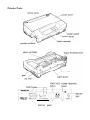


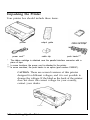
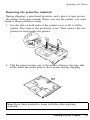
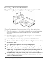
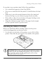
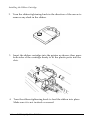


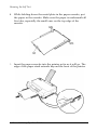


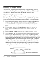
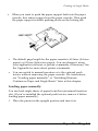

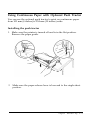
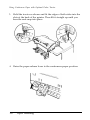
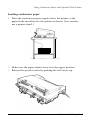

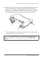
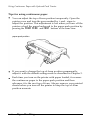


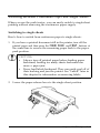
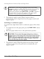
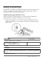

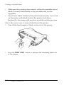
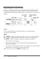
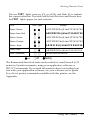
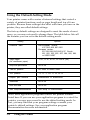
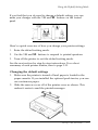
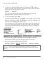
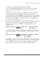
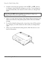

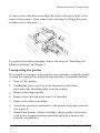


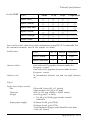


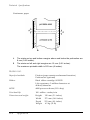

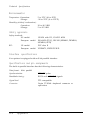
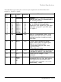
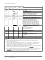
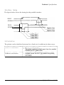
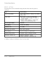
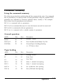
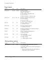
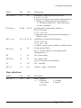

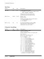
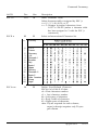
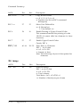
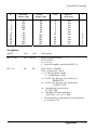
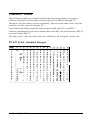
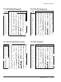
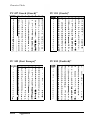

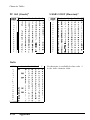
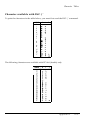


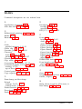
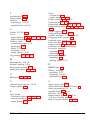
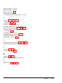

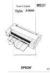

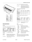

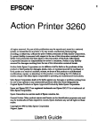
![Hire And Sales Catalogue V4.40 [april2013].](http://vs1.manualzilla.com/store/data/005975062_1-8950e43f7cbe305f577dc550ee5fbd1b-150x150.png)