1
Where to Get Help
Customer support and service for Epson products are provided by a
network of authorized Epson dealers and service centers throughout
the United States. Epson America provides product information and
toll-free support to its dealers and service centers.
Epson is confident that this policy will provide you with the
assistance you need. For service center and technical support
referrals, please call our Consumer Information number:
1-800-922-8911.
Options and Supplies
To locate or purchase ActionPrinter™ accessories or supplies, please
call 1-800-873-7766.
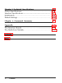
Contents
Introduction
1
About This Guide
2
Chapter 1 Setting Up the Printer
Unpacking the Printer ................................................
Choosing a Place for the Printer ..................................
Assembling the Printer ...............................................
Testing the Printer ....................................................
Connecting the Printer to Your Computer .....................
Printer Selection Menus .............................................
1-1
1-2
1-5
1-7
1-13
1-19
1-21
Chapter 2 Paper Handling
Using Single Sheets . . . . . . . . . . . . . . . . . . . . . . . . . . . . . . . . . . . . . . . . . . . . . . . . . . .
Using Continuous Paper . . . . . . . . . . . . . . . . . . . . . . . . . . . . . . . . . . . . . . . . . . . . .
Printing on Special Paper . . . . . . . . . . . . . . . . . . . . . . . . . . . . . . . . . . . . . . . . . . .
2-1
2-2
2-8
2-20
Chapter 3 Using the Printer
Operating the Control Panel .......................................
DIP Switches ...........................................................
Selecting Typestyles ...................................................
Selecting an International Character Set ........................
Choosing a Character Table ........................................
3-1
3-2
3-5
3-11
3-14
3-16
4-1
Chapter 4 Troubleshooting and Maintenance
Problems and Solutions . . . . . . . . . . . . . . . . . . . . . . . . . . . . . . . . . . . . . . . . . . . . . . 4-2
Cleaning the Printer . . . . . . . . . . . . . . . . . . . . . . . . . . . . . . . . . . . . . . . . . . . . . . . . . . 4-6
Replacing the Ribbon.. . . . . . . . . . . . . . . . . . . . . . . . . . . . . . . . . . . . . . . . . . . . . . . . 4-8
Transporting the Printer.. . . . . . . . . . . . . . . . . . . . . . . . . . . . . . . . . . . . . . . . . . . . 4-11
Contents iii
Chapter 5 Technical Specifications
Printer Specifications .................................................
Interface Specifications ...............................................
Initialization .............................................................
Default Settings ........................................................
5-1
5-2
5-7
5-11
5-12
Chapter 6 Command Summary
6-1
A-1
Appendix
The Interface Boards . . . . . . . . . . . . . . . . . . . .............................. A-2
The Multi-Font Module . . . . . . . . . . . . . . . . . . . . . . . . . . . . . . . . . . . . . . . . . . . . . A-14
Glossary
Index
iv
Contents
Introduction
The ActionPrinter™ L-1000 is an advanced 24-pin impact dot
matrix printer combining a compact design and high performance
with a wide range of features.
Features
In addition to the high-quality printing and ease of operation you
have come to expect from Epson® printers, your printer offers the
following:
Draft mode with fast printing of up to 180 characters per second
in 12 cpi (12 characters per inch).
Two built-in Letter Quality fonts (Roman and Sans Serif) for
producing high-quality documents.
A convenient control panel design that allows for direct
selection of fonts.
Fourteen international character sets, a legal set, italics, and the
Epson Extended Graphics set.
Easy paper handling, featuring automatic single-sheet loading.
Compatibility with the Epson ESC/P® commands used by other
Epson Letter Quality printers.
Introduction 1
About This Guide
This user’s guide provides fully illustrated, step-by-step instructions
for setting up and operating your printer.
Finding your way around
Chapter 1 contains information on unpacking, setting up,
testing, and connecting the printer. Be sure to read and follow
the instructions in this chapter first.
Chapters 2 and 3 include important information on paper
handling and general printer operation. This information is
necessary for the day-to-day operation of your printer.
Other chapters contain information on general maintenance,
specifications, and printer commands. There is also a glossary of
printer terms and an index.
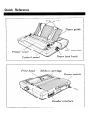
At the back of this manual is a Quick Reference card.
Conventions used in this guide
WARNINGS: must be followed carefully to avoid damage
to your printer and computer.
CAUTIONS: should be followed carefully to ensure that
your printer operates correctly.
Notes: contain important information and useful tips on the
operation of your printer.
2
About This Guide
Chapter 1
Setting Up the Printer
Unpacking the Printer ................................................ 1-2
Removing the pull tractor ........................................ 1-3
Choosing a Place for the Printer .................................. 1-5
Assembling the Printer.. .............................................
Installing the paper feed knob ..................................
Installing the ribbon cartridge ...................................
Attaching the paper guide ........................................
1-7
1-8
1-11
Testing the Printer ....................................................
Plugging in the printer ............................................
Loading a sheet of paper .........................................
Running the self test ...............................................
1-13
1-13
1-14
1-16
1-7
Connecting the Printer to Your Computer ..................... 1-19
The parallel interface .............................................. 1-19
Printer Selection Menus ............................................. 1-21
Choosing from a menu ........................................... 1-21
Setting Up the Printer
1-1
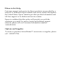
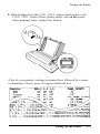
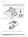
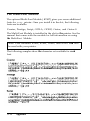
Unpacking the Printer
As you unpack the printer, check that you have all the parts shown
below and that none have been damaged during transportation.
Note: You’ll find the paper feed knob in a piece of the foam
packing. Also, in some locations, the power cable may be
attached to the printer.
1-2
Setting Up the Printer
Unpacking the Printer
After removing the parts, store the packaging materials in case you
ever need to transport your printer.
CAUTION: There are several different versions of the
printer designed for different electrical standards. The
power supply type is shown on the label on the back of
the printer. If it does not show the correct voltage for
your country, contact your dealer. It is not possible to
adjust the printer for use on another voltage.
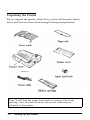
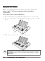
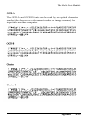
Removing the pull tractor
By removing the pull tractor now, you will be prepared to perform
the printer’s self test later. Follow these steps to remove the pull
tractor:
1. Raise the tractor cover to the upright position. Then lift the
cover up and off.
Note: Remove the packaging material inserted between both sides
of the tractor unit and the tractor cover. Be sure to store this
material with the other packaging materials in case you ever need
to transport the printer.
Setting Up the Printer
1-3
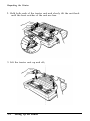
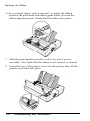
Unpacking the Printer
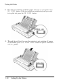
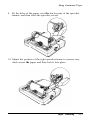
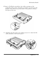
2. Hold both ends of the tractor unit and slowly tilt the unit back
until the front notches of the unit are free.
3. Lift the tractor unit up and off.;
1-4
Setting Up the Printer
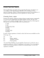
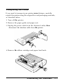
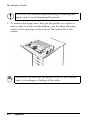
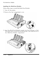
Choosing a Place for the Printer
When you select a location for your printer, keep the following in
mind:
l
l
l
l
Place the printer on a flat, stable surface.
Place the printer close enough to the computer for its cable to
reach.
Leave adequate room around the printer to allow for easy
operation and maintenance.
Use a grounded outlet; do not use an adapter plug.
The illustration below shows a good printer location.
Setting Up the Printer
1-5
Choosing a Place for the Printer
Note: If you plan to use a printer stand, make sure it meets the
following requirements:
l
l
l
l
The stand must support at least 30 lb or 14 kg (twice the
weight of the printer).
The stand must not tilt the printer more than 15 degrees from
horizontal. With a cut sheet feeder, the stand must keep the
printer level.
If the paper supply is below the printer stand, make sure that
the paper cannot catch on the underside of the stand or on
the stand supports.
Make sure that the power cord and the interface cable do not
interfere with paper feeding. If possible, secure them to a
printer stand support.
WARNING:
l
l
l
l
1-6
Avoid locations that are subject to direct sunlight,
excessive heat, moisture, or dust.
Avoid using electrical outlets that are controlled by
wall switches or automatic timers. Accidental
disruption of power can wipe out information both in
your computer’s memory and in your printer’s
memory.
Avoid using outlets on the same circuit with large
motors or other appliances that might disturb the
power supply.
Keep the entire computer system away from potential
sources of interference such as loudspeakers or the
base units of cordless telephones.
Setting Up the Printer
Assembling the Printer
To assemble the printer, you need only do the following:
l
Install the paper feed knob.
l
Install the ribbon cartridge.
l
Attach the paper guide.
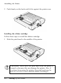
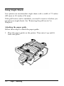
Installing the paper feed knob
The first step in setting up the printer is to install the paper feed
knob. You use this knob to manually feed paper in the printer when
the printer is turned off.
You’ll find the paper feed knob packed in an indentation in the
white foam packing material.
1. Insert the knob into the hole on the printer’s side and rotate it
until it slips onto the six-sided shaft.
Setting Up the Printer
1-7
Assembling the Printer
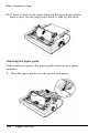
2. Push firmly on the knob until it fits against the printer case.
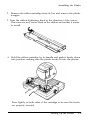
Installing the ribbon cartridge
Follow these steps to install the ribbon cartridge.
1. Slide the print head to the middle of the printer.
CAUTION: Never move the print head while the printer is
turned on because this can damage the printer. Also, if
you have been using the printer, the print head may be
hot; let it cool for a few minutes before touching it.
1-8
Setting Up the Printer
Assembling the Printer
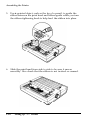
2. Remove the ribbon cartridge from its box and remove the plastic
wrapper.
3. Turn the ribbon-tightening knob in the direction of the arrow.
This removes any excess slack in the ribbon and makes it easier
to install.
4. Hold the ribbon cartridge by its handle and push it firmly down
into position, making sure the plastic hooks fit into the printer.
Press lightly on both sides of the cartridge to be sure the hooks
are properly inserted.
Setting Up the Printer
1-9
Assembling the Printer
5. Use a pointed object, such as the tip of a pencil, to guide the
ribbon between the print head and ribbon guide while you turn
the ribbon-tightening knob to help feed the-ribbon into place.
6. Slide the print head from side to side to be sure it moves
smoothly. Also check that the ribbon is not twisted or creased.
1-10
Setting Up the Printer
Assembling the Printer
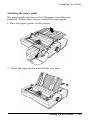
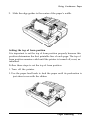
Attaching the paper guide
The paper guide functions to feed the paper smoothly and
efficiently. Follow these steps to install the paper guide:
1. Place the paper guide on the printer.
2. Raise the paper guide until it locks into place.
Setting Up the Printer
1-11
Assembling the Printer
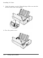
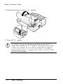
3. Attach the printer cover by fitting the legs of the cover into the
notches at the front of the printer.
4. Close the printer cover.
1-12
Setting Up the Printer
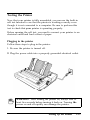
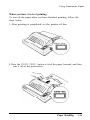
Testing the Printer
Now that your printer is fully assembled, you can use the built-in
self test function to see that the printer is working correctly even
though it is not connected to a computer. Be sure to perform this
test to check that your printer is operating properly.
Before running the self test, you need to connect your printer to an
electrical outlet and load a sheet of paper.
Plugging in the printer
Follow these steps to plug in the printer:
1. Be sure the printer is turned off.
2. Plug the power cable into a properly grounded electrical outlet.
WARNING: After turning the printer off, always wait at
least five seconds before turning it back on. Turning the
power on and off rapidly can damage the printer.
Setting Up the Printer
1-13
Testing the Printer
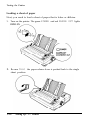
Loading a sheet of paper
Next, you need to load a sheet of paper that is letter or A4 size.
1. Turn on the printer. The green
POWER and red PAPER OUT lights
2. Be sure that the paper release lever is pushed back to the single
sheet position.
1-14
Setting Up the Printer
Testing the Printer
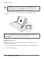
3. Move the left edge guide so it locks in place next to the guide
mark.
4. Adjust the right edge guide to match the width of your paper.
Next, slide a sheet down between the edge guides until it meets
resistance.
Setting Up the Printer
1-15
Testing the Printer
WARNING: Never run the self test using paper that is
narrower than 8¼ inches (210 mm or A4 size) because
then the print head prints directly onto the platen.
5. Press the AUTO LOAD button once to automatically load the
paper.
Note: If the platen turns without loading the paper, remove the
paper and re-insert it more firmly; then press the AUTO LOAD
button again.
Running the self test
The self test can be run in draft mode or Letter Quality mode.
Follow the steps below:
1. Be sure you have loaded a sheet of paper, as described above.
2. Turn off the printer.
1-16
Setting Up the Printer
Testing the Printer
3. While holding down the LINE FEED button (draft mode) or the
FORM FEED button (Letter Quality mode), turn on the printer.
After printing starts, release the button.
A list of your printer’s settings is printed first, followed by a series
of characters. Here is part of a typical draft self test:
Setting Up the Printer
1-17
Testing the Printer
4. The self test continues until the paper runs out or you press the
ON LINE button. If the test results are satisfactory and you wish
to stop the test, press the ON LINE button.
5. To end the self test, be sure the printer is not printing. If paper
is still loaded, press the
off the printer.
1-18
FORM FEED button to eject it. Then turn
Setting Up the Printer
Connecting the Printer to Your Computer
If the self test printed correctly and your printouts looked like the
ones shown, you are now ready to connect your printer to the
computer. If the self test did not print correctly, see “Where to Get
Help” on the inside front cover of this guide.
The printer has a built-in parallel interface. If you have a suitable
shielded cable, you should be able to connect your printer
immediately. If you are unsure whether your computer has a
parallel interface, see your computer’s operating manual.
The parallel interface
Connect the parallel interface cable as described below:
1. Be sure both the printer and computer are turned off.
2. Plug the cable connector securely into the printer.
Setting Up the Printer
1-19
Connecting the Printer to Your Computer
3. Squeeze the wire clips together until they lock in place on either
side of the connector.
Note: If your cable has a ground wire, connect it to the ground
connector beneath the interface connector.
4. Plug the other end of the cable into the computer. (If there is a
ground wire at the computer end of the cable, attach it to the
ground connector at the back of the computer.)
1-20
Setting Up the Printer
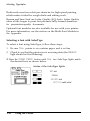
Printer Selection Menus
Most application programs let you specify the type of printer you
are using so that the program can take full advantage of the
printer’s features. Many of these programs provide an installation or
setup section that presents a list of printers to choose from.
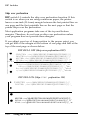
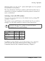
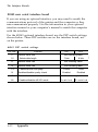
Choosing from a menu
Because the family of Epson printers shares a great many commands,
you can use an application program even if it does not list your
printer on its printer selection menu. Choose from the following list
(the printers are listed in the order of preference):
L-1000
L-750
LQ-850/950/1050
LQ-500
LQ-2550
LQ-800/1000
LQ-1500
If none of these printers is listed, select the first one available on the
following list.
EX
FX
LX
Rx
MX
Epson printer
Standard printer
Draft printer
To use all the features of your printer, however, it is best to use a
program with one of the LQ printers on its menu. If your program
does not list these printers, contact the manufacturer to see if an
update is available.
Setting Up the Printer
1-21
Printer Selection Menus
1-22
Setting Up the Printer
Chapter 2
Paper Handling
Using Single Sheets ...................................................
Attaching the paper guide ........................................
Loading paper .......................................................
Reloading during printing ........................................
2-2
2-2
2-4
Using Continuous Paper .............................................
Installing the pull tractor .........................................
Positioning your continuous paper supply ..................
Loading continuous paper ........................................
Attaching the paper guide ........................................
Setting the top of form position.. ..............................
When you have finished printing ..............................
2-8
2-8
2-7
2-11
2-11
2-16
2-17
2-19
Printing on Special Paper ........................................... 2-20
The paper thickness lever ........................................ 2-20
Using multi-part forms ............................................ 2-22
Paper Handling 2-1
Using Single Sheets
Your printer can accommodate single sheets with a width of 7.2 inches
(182 mm) to 8.5 inches (216 mm).
If the pull tractor unit is installed, you need to remove it before you
can print on single sheets. See “Removing the pull tractor” in
Chapter 1.
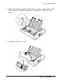
Attaching the paper guide
Follow these steps to attach the paper guide:
1. Place the paper guide on the printer. Then raise it up until it
locks into place.
2-2
Paper Handling
Using Single Sheets
2. Slide the left edge guide until it locks in place at the guide mark.
Next, adjust the right edge guide to match the width of your
paper.
3.
Attach the printer cover.
Paper Handling 2-3
Using Single Sheets
Loading paper
Follow these steps to load paper in the printer:
1. Push the paper release lever back to the single-sheet position.
2. Turn on the printer. The POWER and PAPER
on.
2-4
Paper Handling
OUT lights should be
Using Single Sheets
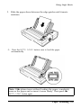
3. Slide the paper down between the edge guides until it meets
resistance.
4. Press the AUTO LOAD button once to load the paper
automatically.
Note: If the platen turns without loading the paper, completely
remove the paper and re-insert it more firmly. Then press the
AUTO LOAD button again.
Paper Handling 2-5
Using Single Sheets
5. Press the ON
LINE button to set the printer on line.
To eject the paper, set the printer off line (by pressing the
button) and then press the FORM FEED button.
ON LINE
CAUTION: Never advance the paper using the paper feed
knob while the printer is turned on.
2-6
Paper Handling
Using Single Sheets
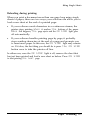
Reloading during printing
When you print a document more than one page long using single
sheets of paper, there are two ways your software can allow you to
load a new sheet at the end of a printed page:
l
l
If your software sends characters in a continuous stream, the
printer stops printing when it reaches the bottom of the paper.
When this happens, the page ejects and the ON LINE light goes
off automatically.
If your software handles printing page by page, it probably
stops sending characters at the end of a page and prompts you
to insert more paper. In this case, the ON LINE light may remain
on. If it does, the first thing you should do is press the ON LINE
button once to take the printer off line.
In either case, once the ON LINE light is off, remove the sheet that
has just been printed and load a new sheet as before. Press ON LINE
to start printing the next page.
Paper Handling 2-7
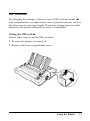
Using Continuous Paper
To print on continuous paper, you need to install the pull tractor
unit. With the pull tractor installed, you can print on continuous
paper with a width of 4 inches (101 mm) to 10 inches (254 mm).
If the pull tractor is already installed, skip to “Positioning your
continuous paper supply” later in this chapter.
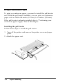
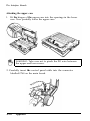
Installing the pull tractor
Follow these steps to install the pull tractor:
1. Turn off the printer and remove the printer cover and paper
guide.
2. Attach the paper rest.
2-8
Paper Handling
Using Continuous Paper
3. Pull the paper release lever forward to the continuous paper
position.
4. Open the slot cover for the tractor unit.
Paper Handling 2-9
Using Continuous Paper
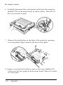
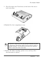
5. Fit the rear notches of the tractor unit over the rear mounting
pins of the printer.
6.
Press the tractor unit forward until its front notches lock onto
the front mounting pins of the printer.
2-10
Paper Handling
Using Continuous Paper
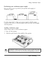
Positioning your continuous paper supply
Here are three ways to position your printer and supply of
continuous paper:
It is also important to align your paper supply with the paper
loaded in the tractor so that the paper feeds smoothly and straight
into the printer.
Loading continuous paper
Follow these steps to load continuous paper.
1. Turn off the printer.
2. Slide the print head to the middle of the printer.
WARNING: If the printer has been used recently, the print
head may be hot. Let it cool before attempting to move it.
Paper Handling
2-11
Using Continuous Paper
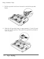
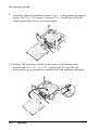
3.
Pull the sprocket lock levers forward to unlock the sprocket
frames.
4. Slide the left sprocket frame to approximately 1/2 inch (12 mm)
from the far left position, Then push the sprocket lever back to
lock it in place.
2-12
Paper Handling
Using Continuous Paper
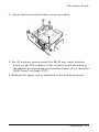
5. Slide the right sprocket frame to match the width of your paper,
but do not lock it.
6. Position the paper support midway between the two sprocket
frames.
Paper Handling
2-13
Using Continuous Paper
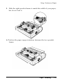
7. Open both sprocket covers.
8. Be sure your paper has a clean, straight edge and then insert the
paper into the printer until it emerges between the platen and
the ribbon guide. Pull it up to the sprocket frames.
2-14
Paper Handling
Using Continuous Paper
9. Fit the holes of the paper over the tractor pins of the sprocket
frames, and then close the sprocket covers.
10. Adjust the position of the right sprocket frame to remove any
slack across the paper and then lock it into place.
Paper Handling
2-15
Using Continuous Paper
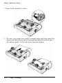
11. If there is slack in the paper between the print head and the
tractor unit, use the paper feed knob to take up the slack.
Attaching the paper guide
With continuous paper, the paper guide functions as a paper
separator.
1. Place the paper guide over the printer and paper.
2-16
Paper Handling
Using Continuous Paper
2. Slide the edge guides to the center of the paper’s width.
Setting the top of form position
It is important to set the top of form position properly because this
position determines the first printable line of each page: The top of
form position remains valid until the printer is turned off, reset, or
initialized.
Follow these steps to set the top of form position.
1. Turn off the printer.
2. Use the paper feed knob to feed the paper until its perforation is
just about even with the ribbon.
Paper Handling
2-17
Using Continuous Paper
3. Attach the tractor cover to the printer.
4. Turn on the printer.
CAUTION: If you use the paper feed knob to feed
the
paper after turning on the printer, the printer loses track
of the set position. If you wish to retain the set top of
form position, be sure to use the LINE FEED or FORM FEED
button to feed paper.
2-18
Paper Handling
Using Continuous Paper
When you have finished printing
To tear off the paper after you have finished printing, follow the
steps below:
1. After printing is completed, set the printer off line.
2. Press the
FORM FEED button to feed the paper forward, and then
tear it off at the perforation.
Paper Handling
2-19
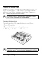
Printing on Special Paper
In addition to printing on single sheets and continuous paper, your
printer can also print on a wide variety of paper types, such as
multi-part forms. Before printing on special types of paper, you
need to change the paper thickness setting.
WARNING: Always return the lever to position 2 when
you go back to printing on ordinary paper.
The paper thickness lever
Change the position of the paper thickness lever as follows:
1. Turn off the printer.
2. Remove the tractor cover or the printer cover.
3. Slide the print head to the middle of the printer.
WARNING: If the printer has been used recently, the print
head may be hot. Let it cool before attempting to move it.
2-20
Paper Handling
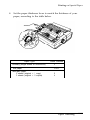
Printing on Special Paper
4. Set the paper thickness lever to match the thickness of your
paper, according to the table below.
Paper Type
Lever Position
Ordinary (single sheets or continuous)
2
Thin paper
2 or 1
Multi-part paper
2 sheets (original + 1 copy)
3 sheets (original + 2 copies)
3
4
Paper Handling
2-21
Printing on Special Paper
5. Attach the tractor cover or printer cover.
Using multi-part forms
With the pull tractor unit installed, your printer can print on
continuous multi-part forms. You can use multi-part forms up to
three sheets thick including the original. Be sure you set the paper
thickness lever to the proper position using the table on the
previous page.
WARNING: Do not use multi-part forms with the single-
sheet feeding system.
Except for the paper thickness lever setting, you load multi-part
paper the same way as continuous paper. For details, see the section
on loading continuous paper in this chapter. Pay special attention to
setting the top of form position.
WARNING: When printing multi-part forms, be sure the
printing does not exceed the printable range of your
forms.
2-22
Paper Handling
Chapter 3
Using the Printer
Operating the Control Panel .......................................
Lights ..................................................................
Buttons ................................................................
Other control panel features .....................................
3-2
3-2
3-3
3-4
DIP Switches ........................................................... 3-5
Setting the DIP switches .......................................... 3-5
DIP switch functions .............................................. 3-7
Selecting Typestyles ...................................................
Built-in character fonts ............................................
Selecting a font with SelecType ................................
Selecting a font with DIP switches ............................
3-11
3-11
3-12
3-13
Selecting an International Character Set ........................ 3-14
Choosing a Character Table ........................................ 3-16
Using the Printer 3 - 1
Operating the Control Panel
The buttons on the control panel let you control many of the
printer settings. The control panel also has indicator lights so you
can check the current status of the printer’s settings.
Lights
POWER:
On when the power switch is on and power is
supplied.
READY:
On when the printer is ready to accept data. This
light flickers during printing.
PAPER OUT:
On when the printer is out of paper.
3-2
Using the Printer
Operating the Control Panel
ON LINE:
On when the printer can receive and print data from
SelecType:
The two SelecType lights indicate which font is
currently selected as indicated by the labels next to
each font name.
the computer. If this light flickers, the print head is
overheated. In this case, the printer waits until the
print head cools and then resumes printing.
:
DRAFT selected
: ROMAN selected
: SANS SERIFselected
: SLOT selected
When draft is selected, neither light is on. When
Roman is selected, the left light is on. When Sans
Serif is selected, the right light is on. When you are
using an optional font module font, both lights are
on.
Buttons
ON LINE:
This button controls the printer’s on line/off line
status. When the printer is on line, the ON LINE light
is on and the printer can receive and print data from
the computer.
FORM FEED:
When the printer is off line, press this button to eject
a single sheet of paper or advance continuous paper
to the top of the next page. When the printer is on
line, press this button to select the character font. See
the section in this chapter on selecting a font with
SelecType.
LINE FEED/
AUTO LOAD:
When the printer is off line, press this button to feed
the paper one line, or hold it down to feed paper
continuously. After inserting a single sheet while the
PAPER OUT light is on, press this button to
automatically load the paper.
Using the Printer
3-3
Operating the Control Panel
Other control panel features
The control panel also gives you access to several special functions.
Self test:
By holding down the LINE FEED button (for draft
mode) or the FORM FEED button (for Letter Quality
mode) while you turn on the printer, you can start
the printer’s self test. The self test printout lets you
check the current DIP switch settings and operating
status of the printer.
LINE FEED:
FORM FEED:
Draft mode
Letter Quality mode
See the section on testing the printer in Chapter 1 for
more information.
Data dump:
3-4
By holding down both the LINE FEED and FORM FEED
buttons while you turn on the printer, you turn on
the data dump mode. This feature allows advanced
users to find the cause of communication problems
between the printer and the software.
Using the Printer
DIP Switches
By changing the settings of the two sets of DIP switches inside the
font compartment, you can control various printer features, such as
the character set and page length. These new settings become valid
whenever the printer is turned on, reset, or initialized.
Setting the DIP switches
Follow these steps to set the DIP switches:
1. Be sure the printer is turned off.
2. Remove the font compartment cover.
Using the Printer
3-5
DIP Switches
3. Use a pointed instrument, such as the tip of a pen, to move the
switch to either the on or the off position. The tables on the
following pages give the DIP switch functions for each setting.
4. Reattach the font compartment cover.
The new settings become valid when you turn on the printer.
3-6
Using the Printer
DIP Switches
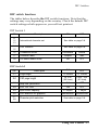
DIP switch functions
The tables below describe the DIP switch functions. Note that the
settings may vary depending on the country. Check the default DIP
switch settings which appear on your self test printout.
DIP Switch 1
OFF
SW
Description
1-1
1-2
1-3
International character set
See table on page 3-8.
1-4
1-5
Font selection
See table on page 3-8.
1-6
Condensed mode
1-7
Character table
1-8
Cut sheet feeder mode
ON
Condensed
Normal
Graphic
Italic
ON
OFF
ON
OFF
DIP Switch 2
Description
SW
2-1
Page length
12 inches
11 inches
2-2
CSF page length
A4 size
Letter size
(65 lines)
(61 lines)
2-3
Skip over perforation
ON
OFF
2-4
Auto line feed
ON
OFF
2-5
Input buffer capacity
8 kbytes
1 kbyte
2-6
Print direction for graphics
2-7
2-8
Character pitch selection
Bidirectional Unidirectional
See table on page 3-8.
Using the Printer 3-7
DIP Switches
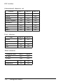
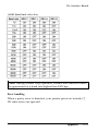
International character set
SW1-1
SW1-2
SW1-3
USA
ON
ON
ON
France
ON
ON
OFF
Germany
ON
OFF
ON
United Kingdom
ON
OFF
OFF
Denmark 1
OFF
ON
ON
Sweden
OFF
ON
OFF
Italy
Spain 1
OFF
OFF
ON
OFF
OFF
OFF
SW1-4
SW1-5
Roman
OFF
OFF
Sans Serif
ON
OFF
Slot
OFF
ON
Draft
ON
ON
Country
Font selection
Font
Pitch selection
SW2-7
SW2-8
10 pitch
Character pitch
OFF
OFF
12 pitch
ON
OFF
15 pitch
OFF
ON
Proportional
ON
ON
3-8
Using the Printer
DIP Switches
Auto line feed
When auto line feed is on (DIP switch 2-4 on), each carriage return
code (CR) is automatically accompanied by the line feed code (LF).
Input buffer capacity
The input buffer stores data from your computer. If you want to
free your computer for other tasks while the printer prints, change
the setting to 8 Kbytes (DIP switch 2-5 on). Before defining userdefined characters, however, be sure to set the switch to 1 Kbyte
(off).
Print direction for graphics
The printer ordinarily prints text bidirectionally for speed and prints
graphics characters unidirectionally for precise vertical alignment.
You can, however, change text printing to unidirectional with the
software command ESC U1. If DIP switch 2-6 is on, you can
change graphics character printing to bidirectional with ESC U0. If
DIP switch 2-6 is off, graphics character printing is unidirectional
whether or not ESC U0 is used.
Page length
DIP switch 2-1 lets you select a page length of 11 inches (27.94 cm)
or 12 inches (30.48 cm). If you are using paper that is 12 inches
long, you can set this switch on. For 11-inch paper the factory
setting is off.
Using the Printer
3-9
DIP Switches
Skip over perforation
DIP switch 2-3 controls the skip over perforation function. If this
switch is on when you are using continuous paper, the printer
leaves a one-inch (25.4 mm) margin between the last printed line on
one page and the first printable line on the next page so that the
printer skips over the perforation.
Most application programs take care of the top and bottom
margins. Therefore, do not turn on skip over perforation unless
your program does not provide these margins.
If you adjust your top of form position to the proper point, you
can get half of the margin at the bottom of one page and half at the
top of the next page as shown below.
DIP SW2-3 OFF (Skip over perforation OFF)
23456789: ;<=>?@ABCDEFGHIJKLMNOPQRSTUVWXYZ[\]
3456789:;<=>?@ABCDEFGHIJKLMNOPQRSTUVWXYZ[\]^
456789:;<=>?@ABCDEFGHIJKLMNOPQRSTUVWXYZ[\]^_
56789:;<=>?@ABCDEFGHIJKLMNOPQRSTUVWXYZ[\]^'_
6789:;<=>?@ABCDEFGHIJKLMNOPQRSTUVWXYZ[\]^_'a
789:;<=>?@ABCDEFGHIJKLMNOPQRSTUVWXYZ[\l^_at
89:;<=>?@ABCDEFGHIJKLMNOPQRSTUVWXYZ[\l]^_'abc
9:;<=>?@ABCDEFGHIJKLMNOPQRSTUVWXYZ[\]^_'abcd
:;<=>?@ABCDEFGHIJKLMNOPQRSTUVWXYZ[\]^_'abcde
DIP SW2-3 ON (Skip over perforation ON)
l 23456789 :;<=>?@ABCDEFGHIJKLMNOPQRSTUVWXYZ[\]'
3456789: ;<=>?@ABCDEFGHIJKLMNOPQRSTUVWXYZ[\]^_
l
456789:;<=>?@ABCDEFGHIJKLMNOPQRSTUVWXYZ[\]^_
56789:;<=>?@ABCDEFGHIJKLMNOPQRSTUVWXYZ[\]^_'a
6789:;<=>?@ABCDEFGHJIKLMNOPQRSTUVWXYZ[\]^_'at
3-10
Using the Printer
Selecting Typestyles
Your printer can produce a wide range of typestyles by using
different character fonts, pitches, widths, and other enhancements.
You can select the character font using a software command, the
SelecType feature on your control panel, or by setting DIP
switches.
Built-in character fonts
Your printer has three built-in character fonts:
DRAFT
!”#$%&'()*+,-./0123456789:;<=>?@ABCDEFGHIJK
LMNOPQRSTUVWXYZ [\]^_’ a b c d e f g h i j k l m n o p q r s t u v
w x y z [ | ]~
W e ’ v e just seen your excellent ad for
m i n i a t u r e z e b r a s in a recent back issue of
T r a d e r ' s t i m e s . What is the price schedule
for quantities over one gross?
ROMAN
!“#$%&‘()*+,-./0123456789:;<=>?@ABCDEFGHIJK
LMNOPQRSTUVWXYZ[\]^-'abcdefghijklmnopqrstuv
~
wxyz[|]
We've just seen your excellent ad for
miniature zebras in a recent back issue of
Trader's Times. What is the price schedule
for quantities over one gross?
SANS SERIF
! " # $ % & ‘ ( ) * + , - ./0123456789:;<=>?O@BCDEFGHIJK
LMNOPQRSTUVWXYZ[\]^-’ a b c d e f g h i j k l m n o p q r s t u v
w x y z [ | ]~
We’ve just seen your excellent ad for
miniature zebras in a recent back issue of
Trader’s Times. What is the price schedule
for quantities over one gross?
Using the Printer
3-11
Selecting Typestyles
Draft mode uses fewer dots per character for high-speed printing,
which makes it ideal for rough drafts and editing work.
Roman and Sans Serif are Letter Quality (LQ) fonts. Letter Quality
takes a little longer to print, but produces fully-formed characters
for presentation-quality documents.
Optional font modules are also available for use with your printer.
For more information, see the section on the Multi-Font Module in
the Appendix.
Selecting a font with SelecType
To select a font using SelecType, follow these steps:
1. Be sure
the printer is on, contains paper, and is on line.
2. Check to see that the printer is not receiving data (the READY
light should not be flickering).
3. Press the FORM FEED button until the two SelecType lights match
the desired font, as shown below.
Status of the SelecType lights
DRAFT selected
ROMAN selected
SANS SERIF selected
SLOT (font module) selected
3-12
Using the Printer
Selecting Typestyles
SelecType skips over the SLOT option (both lights on) if an optional
font module is not installed.
The font selected by SelecType remains valid until another font is
selected by a software command or until the printer is turned off,
reset, or initialized.
Selecting a font with DIP switches
You can set your favorite font as the default font by setting DIP
switches 1-4 and 1-5.
The printer comes with Roman as the default font. If you wish to
change it, set the DIP switches as shown in the table below.
CAUTION: Be sure
the printer is turned off before
changing any DIP switch settings.
Font
SW1-4
SW1-5
Roman
OFF
OFF
Sans Serif
ON
OFF
Slot
OFF
ON
Draft
ON
ON
In addition to font selection, you can also change the character
pitch and add other print enhancements by using software
commands listed in the Command Summary, Chapter 6.
Using the Printer
3-13
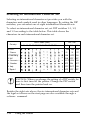
Selecting an International Character Set
Selecting an international character set provides you with the
characters and symbols used in other languages. By setting the DIP
switches, you can select one of eight international character sets.
To select an international character set, set DIP switches 1-1, 1-2,
and 1-3 according to the table below. This table shows the
characters in each international character set.
Country
ASCII code (hex)
23 24 40 5B 5C 5D 5E 60 7B 7C 7D 7E
DIP SW
1-1
1-2
1-3
0 USA
ON
ON
ON
1 France
ON
ON
OFF
2 Germany
ON
3 UK
ON OFF OFF
OFF ON
4 Denmark I
OFF ON ON
5 Sweden
OFF
ON
OFF
6 Italy
OFF OFF ON
7 Spain I
OFF OFF OFF
CAUTION: When you change the setting of a DIP switch, be
sure to first turn off the printer. Change the DIP switch
and then turn the printer back on.
Besides the eight sets above, the six international character sets and
the legal set shown on the next page are also available through a
software command.
3-14
Using the Printer
Selecting an International Character Set
Country
ASCII code (hex)
23
24
40
5B
5C
5D
5E
60
7B
7C
7D
7E
8 Japan
9 Norway
10 Denmark II
11 Spain II
12 Latin America
13 Korea
64 Legal
Using the Printer
3-15
Choosing a Character Table
DIP switch 1-7 selects the italics character table or the Epson
Extended Graphics character table. The Epson Extended Graphics
table contains international accented characters, Greek characters,
mathematical symbols, and character graphics for printing lines,
comers, and shaded areas.
If you have an IBM ® or compatible computer, select Epson
Extended Graphics by setting DIP switch 1-7 on. You can then print
both text and the character graphics that are displayed on your
screen. Also you can still print italics using the ESC 4 command.
Samples of italics and Epson Extended Graphics are shown below.
Italics
! "#$%&'()*+, -. /0123456789:;<=>?@ABCDEFG
HIJKLMNOPQRSTUVWXYZ[\]^_'abcdefghijklmno
~
pqrstuvwxyz{|}
Epson Extended Graphics
CAUTION: When you change the setting of a DIP switch,
be sure to first turn off the printer. Change the DIP
switch and then turn the printer back on.
3-16
Using the Printer
Chapter 4
Troubleshooting and Maintenance
Problems and Solutions ..............................................
The printer does not print .......................................
The printout is spaced incorrectly .............................
The printout is faint or uneven .................................
The printer stops printing ........................................
Single sheets do not feed properly .............................
Continuous paper does not feed properly ...................
The printout is not what you expect ..........................
4-2
4-2
4-3
4-3
4-4
4-4
4-5
4-5
Cleaning the Printer . . . . . . . . . . . . . . . . . . . . . . . . . . . . . . . . . . . . . . . . . . . . . . . . . . 4-6
Replacing the Ribbon . . . . . . . . . . . . . . . . . . . . . . . . . . . . . . . . . . . . . . . . . . . . . . . . . 4-8
Transporting the Printer . . . . . . . . . . . . . . . . . . . . . . . . . . . . . . . . . . . . . . . . . . . . . 4-11
Troubleshooting and Maintenance
4-1
Problems and Solutions
This chapter discusses problems you may encounter and their likely
solutions.
This section lists possible problems and likely solutions. For
additional information, see “Where to Get Help” on the inside front
cover of this guide.
The printer does not print
l
l
l
l
Be sure that the printer is turned on and the POWER light is on.
If the printer is turned on but the POWER light is not on, check
to see that the printer is fully plugged in and that the electrical
outlet is also turned on.
Be sure that the ON
LINE button.
LINE light is on. If it is not on, press the ON
Be sure that the printer is connected to the computer. Check
both ends of the cable between the printer and the computer.
Be sure that the printer is not out of paper. (The
light should be off.)
PAPER OUT
If the printer still does not print, disconnect the printer from the
computer and try the self test described in Chapter 1. If the self test
works properly, the printer is working, and the problem probably
lies in the computer, the software, or the cable. If the self test does
not work, contact the store where you purchased your printer or
call the Epson toll-free number.
4-2
Troubleshooting and Maintenance
Problems and Solutions
The printout is spaced incorrectly
Text is printed all on one line, or the printer is inserting extra blank
lines between lines of text.
l
If all the text is printed on the same line, no line feed signal is
being sent at the end of each line of text. Turn DIP switch 2-4
on.
l
l
If the printer is inserting extra blank lines between lines of text,
extra line feed signals are being sent. Turn DIP switch 2-4 off.
If the printer inserts extra blank lines even after turning DIP
switch 2-4 off, you may need a different cable which disables
the AUTO FEED XT signal of your interface.
The printout is faint or uneven
The ribbon may not be properly installed. See the section on
ribbon installation in Chapter 1.
The ribbon may be worn out. See the section on replacing the
ribbon later in this chapter.
The paper thickness lever may be in the wrong position. See the
section on the paper thickness lever in Chapter 2.
The print head may be worn out. This is especially likely if
parts of printed characters are missing. Contact an Authorized
Epson Dealer to have the head replaced. Never attempt to
replace the head yourself because other parts of the printer
should be checked at the same time.
Troubleshooting and Maintenance 4-3
Problems and Solutions
The printer stops printing
l
l
l
l
l
The printer may be out of paper. Check the paper supply.
The paper may be jammed. Remove the jammed paper and
reload.
The ribbon may be jammed. See the section on replacing the
ribbon later in this chapter.
If the READY light is off and the ON LINE light is flickering, the
printer has stopped to allow the print head to cool. Printing
resumes soon; you do not have to do anything to restart it.
If the printer stops, the beeper sounds, and the ON LINE light
does not flicker, turn the printer off and then turn it back on
and try to print again. If the printer beeps again and does not
print, take it to a qualified service person.
Single sheets do not feed properly
l
l
l
l
4-4
The position of the paper release lever may be wrong. Push it
back to the single-sheet position.
The paper may be too large or too small. See the printer’s paper
specifications in Chapter 5.
The paper guide may not be installed properly. See
on installing the paper guide in Chapter 2.
the section
The cut sheet feeder mode may be selected by the DIP switch.
See the section on setting DIP switches in Chapter 3.
Troubleshooting and Maintenance
Problems and Solutions
Continuous paper does not feed properly
The position of the paper release lever may be wrong. Pull it
forward to the continuous paper position.
The paper may not be mounted on the sprockets correctly. See
that the sprocket holes of the paper fit correctly over the
sprockets.
The paper guide may not be installed properly. See the section
on continuous paper in Chapter 2.
The paper supply may be stacked too far from the printer or
not aligned with the tractor. Also, there may be some obstacle
in the way of the paper or something on top of the paper
supply. See Chapter 2 for instructions on the proper placement
of the paper supply.
The printout is not what you expect
The wrong international character set may be selected. See the
section on international character sets in Chapter 3.
The wrong character table (italics or Epson Extended Graphics)
may be selected. See the section on character tables in Chapter 3.
The font, pitch, or size may not be selected properly. See that
your software is correctly set up for your printer.
Your application program may be changing the SelecType
settings. Use the program’s setup (or installation) procedure to
remove the codes that interfere with your SelecType settings.
Another solution is to use the printer control codes for your
application program instead of SelecType to control your
printing. The manual for your program can tell you how to
change the printing style.
Troubleshooting and Maintenance
4-5
Cleaning the Printer
To keep your printer operating at its best, you should clean it
thoroughly several times a year.
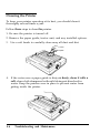
Follow these steps to clean the printer.
1. Be sure the printer is turned off.
2. Remove the paper guide, tractor unit, and any installed options.
3. Use a soft brush to carefully clear away all dust and dirt.
4. If the outer case or paper guide is dirty or dusty, clean it with a
soft, clean cloth dampened with mild detergent dissolved in
water. Keep the printer cover in place to prevent water from
getting inside the printer.
4-6
Troubleshooting and Maintenance
Cleaning the Printer
WARNING:
l
Never use alcohols or thinners to clean the printer;
these chemicals can damage the components as well as
the case.
l
l
l
Be careful not to get water on the printer mechanism
or electronic components.
Do not use a hard or abrasive brush.
Do not spray the inside of the printer with lubricants;
unsuitable oils can damage the mechanism. Contact
your Authorized Epson Dealer if lubrication is needed.
Troubleshooting and Maintenance
4-7
Replacing the Ribbon
When your printing becomes too faint you need to replace the
ribbon. The # 7753 Epson replacement ribbon cartridge is
recommended.
Follow these steps to replace the ribbon:
1. Be sure the printer is turned off and printer cover is removed.
2. To remove the ribbon cartridge, lift it straight up and out of the
printer.
3. Slide the print head to the middle of the printer.
WARNING: If the printer has been used recently, the print
head may be hot. Let it cool before attempting to replace
the ribbon.
4-8
Troubleshooting and Maintenance
Replacing the Ribbon
4. To remove excess slack in the new ribbon, turn the ribbontightening knob in the direction of the arrow.
5. Push the new ribbon cartridge firmly into position, making sure
the plastic hooks fit into the printer.
Note: Press lightly on both sides of the cartridge to be sure the
hooks are properly inserted.
Troubleshooting and Maintenance 4-9
Replacing the Ribbon
6. Use a pointed object, such as a pencil, to guide the ribbon
between the print head and ribbon guide while you turn the
ribbon-tightening knob to help feed-the ribbon into place.
7.
Slide the print head from side to side to be sure it moves
smoothly. Also check that the ribbon is not twisted or creased.
8. Insert the legs of the printer cover into the printer, then tilt the
printer cover back into place.
4-10
Troubleshooting and Maintenance
Transporting the Printer
If you need to transport your printer some distance, carefully
repack the printer using the original box and packaging materials,
as described below.
1. Turn off the printer.
2. Remove the paper guide and paper rest.
3. Unplug the power cable from the electrical outlet; then
disconnect the interface cable from the printer.
4. Remove the ribbon cartridge and paper feed knob.
Troubleshooting and Maintenance
4-11
Transporting the Printer
5. If you have removed the pull tractor and the tractor cover,
replace them now according to the instructions in Chapter 2.
WARNING: Never hold the printer by the font
compartment cover-even if you are only carrying the
printer a short distance. This cover could come off and
cause you to drop the printer.
4-12
Troubleshooting and Maintenance
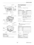
Chapter 5
Technical Specifications
Printer Specifications .................................................
Printing ................................................................
Paper ...................................................................
Mechanical ...........................................................
Electrical ..............................................................
Environmental .......................................................
5-2
5-2
5-3
5-5
5-5
5-6
Interface Specifications . . . . . . . . . . . . . . . . . . . . . . . . . . . . . . . . . . . . . . . . . . . . . . . 5-7
Initialization . . . . . . . . . . . . . . . . . . . . . . . . . . . . . . . . . . . . . . . . . . . . . . . . . . . . . . . . . . . . . 5-11
Default Settings . . . . . . . . . . . . . . . . . . . . . . . . . . . . . . . . . . . . . . . . . . . . . . . . . . . . . . . . 5-12
Technical Specifications 5-1
Printer Specifications
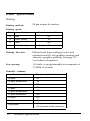
Printing
Printing method:
24-pin impact dot matrix
Printing speed:
Pitch
Quality
10
draft
10
Letter Quality
12
draft
12
Letter Quality
Characters/second/line
150
50
180
60
Printing direction:
Bidirectional logic-seeking for text and
unidirectional for dot graphics printing and
character graphics printing. See page 3-9
for further information.
Line spacing:
1/6 inch, or programmable in increments of
1/180th of an inch
Printable columns:
Character pitch
Maximum printed characters
10 pitch
80
10 pitch double-wide
40
10 pitch condensed
137
12 pitch
96
12 pitch double-wide
48
12 pitch condensed
160
15 pitch
120
15 pitch double-wide
Proportional
5-2
60
68 (maximum width character)
160 (minimum width character)
Technical Specifications
Printer Specifications
1 Kbyte or 8 Kbytes (DIP switch selectable)
Buffer:
Character fonts:
Font
Available Pitches
(characters per inch)
Epson Draft
10, 12, 15
Epson Roman
10, 12, 15, proportional
Epson Sans Serif
10, 12, 15, proportional
Courier (optional)
10, 12, 15
Prestige (optional)
10, 12, 15
Script (optional)
10, 12, 15
OCR-B (optional)
10
OCR-A (optional)
10
Orator (optional)
10
Orator-S (optional)
10
Character tables:
96 standard ASCII characters
14 international character sets and a legal
set
Epson Extended Graphics characters
Paper
Paper feed methods:
Paper width:
Friction
Single-bin cut sheet feeder (optional)
Pull tractor
Single sheets
7.2 to 10.1 inches (182 to 257 mm)
Continuous
4.0 to 10.0 inches (101 to 254 mm)
Paper length:
Single sheets
7.2 to 14.3 inches (182 to 364 mm)
Technical Specifications 5-3
Printer Specifications
Printable area:
3 mm (0.12")
or more
9 mm (0.35")
or more
101 to 242 mm (4.0 to 9.5”) paper width
13 mm (0.51”) or more on both sides
13.5 mm (0.53“) or more
254 mm (10") paper width
Left side : 26 mm (1.02”) or more
Right side : 24 mm (0.94“) or more
* This distance is 27 mm (1.06 inches) if the paper width is 257 mm
(10.1 inches).
Paper feed speed:
Paper thickness:
Approx. 100 ms/line at l/6-inch line
spacing with intermittent feeding;
2.2 inches/s with continuous feeding.
Single sheets
0.0025 to 0.004 inches (0.065 to 0.1 m m )
Continuous
0.0025 to 0.01 inches (0.065 to 0.25 mm)
Number of copies:
5-4
With continuous multi-part paper only;
one original plus up to two copies.
Maximum thickness: 0.01 inches (0.25 mm)
Technical Specifications
Printer Specifications
Mechanical
Ribbon:
Cartridge ribbon, available in black only
( # 7753).
Do not use ribbons for 9-pin printers.
Life expectancy (in Letter Quality
characters, at 48 dots/character): 2 million
MCBF:
For all components excluding print head:
3 million lines
MTBF:
4000 power on hours
Print head life:
200 million strokes per wire
Dimensions and weight; Height:
Width:
Depth:
Weight:
139 mm (5.5 inches)
390 mm (15.3 inches)
320 mm (12.6 inches)
7 Kg (15 lb)
Electrical
Voltage:
120 VAC ±10% (120 V model)
220 VAC ±10% (220 V model)
240 VAC ±10% (240 V model)
Power consumption:
120 Watts maximum
Frequency:
49.5 to 50.5 Hz (50 Hz version)
59.5 to 60.5 Hz (60 Hz version)
Insulation resistance:
10
Dielectric strength
(between AC line
and chassis):
between AC power line and chassis
120 V model:
AC 1.0 kV (rms), 1 minute
AC 1.2 kV (rms), 1 second
220/240 V model:
AC 1.25 kV (rms), 1 minute
AC 1.5 kV (rms), 1 second
Technical Specifications 5-5
Printer Specifications
Environmental
Temperature:
Operation: 41°F to 95°F (5°C to 35°C)
-22°F to 140°F ( -30°C to 60°C)
Storage:
Humidity:
Operation: 10% to 80% without condensation
5% to 85% without condensation
Storage:
Shock:
Operation: Up to 1 G within 1ms
Up to 2 G within 1ms
Storage:
Vibration:
Operation: Up to 0.25 G at up to 55 Hz
Up to 0.50 G at up to 55 Hz
Storage:
5-6
Technical Specifications
Interface Specifications
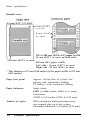
Your printer is equipped with a parallel interface.
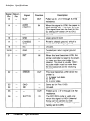
Pin assignments for the parallel interface
Connector pin assignments and a description of their respective
interface signals are shown in the following table.
signal Return
Pin
Pin
Signal
Direction
Description
1
19
STROBE
IN
STROBE pulse to read data. Pulse
width must be more than 0.5
microseconds at the receiving
terminal.
2
3
4
5
6
7
8
9
20
21
22
23
24
25
26
27
DATA 1
DATA 2
DATA 3
DATA 4
DATA 5
DATA 6
DATA 7
DATA 8
IN
IN
IN
IN
IN
IN
IN
IN
These signals represent information
of the 1st to 8th bits of parallel data,
respectively. Each signal is at HIGH
level when data is logical 1 and
LOW when it is logical 0.
10
28
ACKNLG
OUT
About an 11-microsecond pulse.
LOW indicates that data has been
received and that the printer is ready
to accept more data.
11
29
BUSY
OUT
A HIGH signal indicates that the
printer cannot receive data. The
signal goes HIGH in the following
cases:
1) During data entry (ea. char. time)
2) During printing
3) When off line
4) During printer-error state
12
30
PE
OUT
A HIGH signal indicates that the
printer is out of paper.
Technical Specifications 5-7
Interface Specifications
5-8
Technical Specifications
Interface Specifications
Note:
1. The column heading “Direction” refers to the direction of
signal flow as viewed from the printer.
2. “Return” denotes the twisted-pair return, to be connected at
signal ground level. For the interface wiring, be sure to use a
twisted-pair cable for each signal and to complete the
connection on the return side.
3. All interface conditions are based on TTL level. Both the rise
and the fall times of each signal must be less than 0.2
microseconds.
4. Data transfer must be carried out by observing the ACKNLG
or BUSY signal. (Data transfer to this printer can be carried
out only after receipt of the ACKNLG signal or when the
level of the BUSY signal is LOW.)
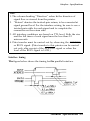
Interface timing
The figure below shows the timing for the parallel interface.
Technical Specifications 5-9
Interface Specifications
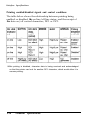
Printing enabled/disabled signals and control conditions
The table below shows the relationship between printing being
enabled or disabled, the on line/off line status, and the receipt of
the data on/off control characters, DC1 or DC3.
*
While printing is disabled, character data is being received and acknowledged
so that the printer can look for another DC1 character, which would allow it to
resume printing.
5-10
Technical Specifications
Initialization
There are three ways that the printer can be initialized (returned to
a fixed set of conditions).
Hardware initialization
1. The power is turned on.
2. The printer receives an INIT signal at the parallel
interface (pin 31 goes LOW).
Software initialization
3. Software sends the ESC @ (Initialize the printer)
command.
These three kinds of initialization have slightly different effects. In
particular, ESC @ resets the font to the current SelecType setting;
the other two methods reset the typestyle according to the default
settings selected by the DIP switches within the font compartment.
Also, ESC @ does not initialize the printer mechanism, clear the
input data buffer, or clear the user-defined character set.
Technical Specifications
5-11
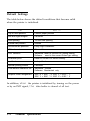
Default Settings
The table below shows the default conditions that become valid
when the printer is initialized.
Item
Reset to:
Top of form position
Current paper position
Left and right margins
Cancelled
Line spacing
1/6-inch line spacing
Vertical tab position
Cleared
Horizontal tab positions
Every eight characters
VFU channel
Channel 0
Font selection
Hardware: reset to current DIP switch setting.
Software: reset to the current SelecType setting.
Character pitch
Reset to current DIP switch setting.
Justification
Left justification
Special printing effects
Cancelled
User-defined character set
Hardware: cleared
Software: Deselected only
Graphic mode assignment
ESC K = ESC * 0, ESC L = ESC * 1,
ESC Y = ESC * 2, ESC Z = ESC * 3
In addition, when the printer is initialized by turning on the power
or by an INIT signal, the data buffer is cleared of all text.
5-12
Technical Specifications
Chapter 6
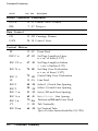
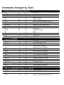
Command Summary
This summary contains all the commands used by the printer. If a
command has no parameters, it is merely listed. If it has parameters,
they are explained. The parameters are indicated by lowercase
italicized letters, usually n. The examples below show how the
parameters are indicated.
ESC @ is a command with no parameters.
ESC U l/0 is a command that uses 1 to turn the feature on and 0 to
turn it off.
ESC $ n1 n2 is a command with two parameters.
ESC D nn is a command with a variable number of parameters.
ASCII
Dec. Hex.
Description
Printer Operation
ESC@
64 40
Initialize Printer
DC1
17 11
Select Printer
DC3
19 13
Deselect Printer
DEL
127 7F Delete Character
ESC <
60 3C
Select Unidirectional Mode (one line)
ESC U 1/0
85 55 Turn Unidirectional Mode On/Off
ESCEMn
25 19
Control Cut Sheet Feeder Mode
4: Turns mode on
R: Ejects a sheet
0: Turns mode off
Note: For the ESC EM command the variables are the characters “0" (48 decimal
or 30 hex) and "4" (52 decimal or 34 hex). Do not use 1 decimal, 01 hex, 4 decimal,
or 04 hex.
ESC=
61 3D
Set MSB to 0
ESC>
6 2 3E
Set MSB to 1
Command Summary 6-1
Command Summary
Dec. Hex.
ASCII
Description
Printer Operation (continued)
ESC#
35 23 Cancel MSB Control
7 07 Beeper
BEL
Data Control
CR
13 0D Carriage Return
CAN
24 18 Cancel Line
Vertical Motion
FF
12 0C
Form Feed
ESC C n
67 43
Set Page Length in Lines
n = no. of lines (1-127)
ESC C0 n
67 43
Set Page Length in Inches
n = no. of inches (1-22)
ESC N n
78 4E
Set Skip Over Perforation
n = no. of lines (1-127)
ESC 0
79 4F
Cancel Skip Over Perforation
LF
10 0A
Line Feed
ESC 0
48 30
Select 1 /8-inch Line Spacing
ESC 2
50 32
Select 1/6-inch Line Spacing
ESC 3 n
51
Set n/180-inch Line Spacing
ESC A n
65 41
Set n/60-inch Line Spacing
ESC J n
74 4A
Perform n/180-inch Line Feed
VT
11 0B
Tab Vertically
ESC B nn
66 42
Set Vertical Tabs
Up to 16 tabs; last n should be 0 (1-255)
6-2
33
Command Summary
Command Summary
ASCII
Dec. Hex.
Description
Vertical Motion
ESC b nn
98 62
Set Vertical Tabs in Channels
Same as ESC B except the first n selects a
channel for tabs.
ESC / n
47 2F Select Vertical Tab Channel
n = the vertical tab channel (0-7)
Horizontal Motion
ESC l n
ESC Q n
BS
108 6C
81
51
8 08
Set Left Margin
n = left margin column
Set Right Margin
n = right margin column
Backspace
ESC $ n1 n2 36 24
Set Absolute Print Position
Specifies print position from the left
margin in 1/60-inch units
Total units = n1 + (n2 x 256)
ESC \ nl n2
Set Relative Print Position
Moves current print position in units of
1/120 inch for draft and 1/180 for LQ
Total units = n1 + (n2 x 256)
HT
ESC D nn
92 5C
9 09
68 44
Tab Horizontally
Set Horizontal Tabs
Up to 32 tabs (1-255) entered in ascending
order
Terminated by 0
Command Summary 6-3
Command Summary
ASCII
Dec. Hex.
Description
Overall Printing Style
ESC x n
120 78
Select Letter Quality or Draft
1: Letter Quality
0: Draft
ESC k n
107 6B
Select Typestyle Family
(Typestyles 2-8
5: OCR-B
0: Roman
available
only if
1: Sans Serif 6: OCR-A
the Multi-Font
7: Orator
2: Courier
8: Orator-S Module is
3: Prestige
installed)
4: Script
ESC ! n
33 21
Master Select
To find the value of n add together the
numbers of the typestyles you want to
combine from the list below:
10 pitch: 0 decimal, 00hex; 12 pitch: 1,01;
proportional: 2,02; condensed: 4,04;
emphasized: 8,08; double-strike: 16,10;
double-wide: 32,20; italics: 64,40;
underline: 128,80
Print Size and Character Width
ESC P
80 50
Select 10 CPI
ESC M
77 4D
Select 12 CPI
ESC g
103 67
Select 15 CPI
E S C p1 / 0
112
Turn Proportional Mode On/Off
70
SI
15 OF
Select Condensed Mode
ESC SI
15 OF
Select Condensed Mode
DC2
18
Cancel Condensed Mode
SO
14 0E
6-4
12
Select Double-wide Mode (one line)
Command Summary
Command Summary
ASCII
Dec. Hex.
Description
Print Size and Character Width (continued)
ESC SO
14 0E
ESC W 1/0
87 57 Turn Double-wide Mode On/Off
DC4
20 14 Cancel Double-wide Mode (one line)
ESC w 1/0
Select Double-wide Mode (one line)
119 77 Turn Double-high Mode On/Off
Print Enhancement
ESC E
69 45
Select Emphasized Mode
ESC F
70 46
Cancel Emphasized Mode
ESC G
71 47
Select Double-strike Mode
ESC H
72 48
Cancel Double-strike Mode
ESC S0
83 53
Select Superscript Mode
ESC S1
83 53
Select Subscript Mode
ESC T
84 54
Cancel Superscript/Subscript Mode
ESC (-nn
40 28
Select Score
ESC(-301n1n2
n1 = 1: Underline
n1 = 2: Strikethrough
n1 = 3: Overscore
n2 = 0: Cancel score line selected by n1
n2 = 1: Single continuous line
n2 = 2: Double continuous line
n2 = 5: Single broken line
n2 = 6: Double broken line
ESC - 1/0
45 2D
Turn Underline Mode On/Off
Command Summary 6-5
Command Summary
Dec. Hex.
ASCII
Description
Print Enhancement (continued)
ESC 4
52 34 Select Italic Mode
ESC 5
53 35 Cancel Italic Mode
ESC q n
113 71 Select Character Style
0: Normal style
1: Outline
2: Shadow
3: Outline with shadow
Word Processing
ESC a n
97 61 Select Justification
0: Left justification
1: Centering
2: Right justification
3: Full justification
ESC SP n
32 20 Set Intercharacter Space
n= number of units of space added to the
space between characters (1-127)
Units are 1/120 inch (draft) and 1/180 inch
(LQ and proportional)
Character Tables
ESC t n
6-6
116 74 Select Character Tables
Selects character table for codes 128-255
0: Italic
1: Extended Graphics
2: Re-maps download characters from
0-127 to 128-255
Command Summary
Command Summary
ASCII
Dec. Hex.
Description
Character Tables (continued)
ESC R n
82 52
Select an International Character Set
0: USA 1: France 2: Germany 3:UK
4: Denmark 5: Sweden 6: Italy 7: Spain
8: Japan 9: Norway 10: Denmark II
11: Spain II 12: Latin America 13: Korea
64: Legal
User-defined Characters
ESC & nn
38 26
Define User-defined Characters
ESC & 0 n1 n2 d0 d1 d2 data
n1 = code for first character; n2 = code for
last character; d0 = left space of character;
d1 = Body width of character; d2 = right
space of character
data: 3 bytes required for each column;
super/subscripts require only 2 bytes per
column
Copy ROM to RAM
n= font family
0: Roman
(Fonts in font cartridges
1: Sans Serif can also be copied)
ESC :0 n 0
58 3A
ESC % n
37 25
Select User-defined Set
0: Normal set
1: User-defined set
ESC 6
54 36
Enable Printable Characters
With Extended Graphics this command
enables the printing of codes 128-159
ESC 7
55 37
Enable Upper Control Codes
Cancels ESC 6
Command Summary 6-7
Command Summary
ASCII
Dec. Hex.
Description
Graphics
ESC K n1 n2
75 4B
Select Single-density Graphics Mode
ESC L n1 n2
76 4C Select Double-density Graphics Mode
ESC Y n1 n2 89 59 Select High-speed Double-density
ESC Z n1 n2
90 5A Select Quadruple-density Graphics
ESC * m n1 n2 42 2A
ESC K,L,Y, and Z each select an 8-pin
mode
Total columns = n1 + (n2 x 256)
Select Graphics Mode
Total columns = n1 + (n2 x 256)
Option
Single-density
Double-density
High-speed double-density*
Quadruple-density*
CRT I
CRT II
Single-density
Double-density
CRT III
Triple-density
Hex-density*
Pins
m
Horiz. dots/inch
a
a
0
1
8
2
a
a
a
3
4
6
60
120
120
240
40
24
24
24
24
24
32
33
38
39
40
* Adjacent dots cannot be printed in this mode.
ESC ? s m
6-8
63 3F Reassign Graphics Mode
s = K,L,Y, or Z
m = mode (0-6)
Command Summary
90
60
120
90
180
360
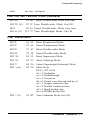
Appendix
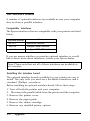
The Interface Boards.. ...............................................
Compatible interface .............................................
Installing the interface board ...................................
#8143 new serial interface board .............................
A-2
A-2
A-2
A-12
The Multi-Font Module ............................................. A-14
Installing the Multi-Font Module .............................. A-16
Selecting the Multi-Font Module .............................. A-17
Appendix A - 1
The Interface Boards
A number of optional interfaces are available in case your computer
does not have a parallel interface.
Compatible interfaces
The Epson interfaces that are compatible with your printer are listed
below.
Name
Interface number
#8143
New serial interface
#8148
Intelligent serial interface
#8165
Intelligent IEEE-488 interface
If you are unsure whether you need an optional interface or would
like to know more about interfaces, contact your Epson dealer.
Note: Please note that not all of these interfaces are available in
all countries.
Installing the interface board
The optional interface boards available for your printer are easy to
install. The only tools you need are a flat-blade screwdriver and a
crosshead (Phillips) screwdriver.
Before installing an optional interface board, follow these steps:
1. Turn off both the printer and your computer.
2. Disconnect the parallel cable from the printer and the computer.
3. Remove the printer cover.
4. Remove the paper guide.
5. Remove the ribbon cartridge.
6. Remove any installed printer options.
A-2
Appendix
The Interface Boards
Removing the upper case
WARNING: High voltages are present inside the printer
when the power is on. Do not attempt to remove the
upper case unless the printer is turned off and the power
cord is unplugged.
Also, try not to touch contacts on the circuit board of the
printer because many of the components can be destroyed
by the static electricity present in your body.
1. Unplug the power cable from the electrical outlet.
2. Remove the font compartment cover.
Appendix A - 3
The Interface Boards
CAUTION: Use caution when removing or attaching the
upper case to avoid damaging the printer.
3. To remove the upper case, first put the printer on a table or
desk so that its front extends slightly over the edge, allowing
access to the openings on the front of the underside of the
printer.
WARNING: Be sure that the printer is not so far forward
that it is in danger of falling off the table.
A-4
Appendix
The Interface Boards
4. Insert a flat-blade screwdriver into either opening on the
underside of the printer. Push the screwdriver up and press the
handle of the driver toward the back of the printer to release
the clips on the case.
5. Partially raise the upper case, taking care not to strain the flat
cable attached to the control panel.
Appendix A-5
The Interface Boards
6. Carefully disconnect the control panel cable from the connector
labelled CN4 on the main board, as shown below. Then lift off
the cover and set it aside.
7. Remove the shield plate on the back of the printer by pressing
in on the plastic clips located at the back of the plate.
8. Using a cross-head screwdriver, remove the screw labelled CG
(shown on the next page) from the main board. Then set it aside
in a safe place.
A-6
Appendix
The Interface Boards
Note: Two screws are labelled CG. Be sure to remove the one
indicated in the illustration below.
Installing the board
There are two basic types of interface board designs-the frame
ground (FG) wire is attached for one type and not attached for the
other. This difference does not affect the operation of the interface
in any way.
1. If the interface board comes with an FG (frame ground) wire
that is not already attached to the board, attach the wire as
shown below on the left.
FG wire not attached
FG wire attached
Appendix A-7
The Interface Boards
2. Carefully place the interface board next to the printer as shown
below. Use the CG screw to connect the round end of the FG
(frame ground) wire to the main board.
3. Holding the interface board level, rotate it clockwise into
position and attach it to the main board. Be sure that the
connector pins are properly inserted into the mating connector.
A-8
Appendix
The interface Boards
4. Secure the board with the three screws provided.
5. For all interface boards except the #8143 new serial interface
board, set the DIP switches on the interface board according to
the manual accompanying your interface board. (If you have the
#8143 board, see page A-12.)
6. Reattach the upper case as described in the following section.
Appendix A-9
The Interface Boards
Attaching the upper case
1. Fit the hinges of the upper case into the openings in the lower
case. Now partially lower the upper case.
WARNING: Take care not to pinch the FG wire between
the upper and lower cases.
2. Carefully insert the control panel cable into the connector
labelled CN4 on the main board.
A-10
Appendix
The Interface Boards
3. Close the upper case. Press down on the front of the case to
lock it into place.
4. Reattach the font compartment cover.
WARNING: When you use the optional interface, be sure
to disconnect the printer cable from the printer’s built-in
parallel interface. You should never leave two interface
cables connected at the same time.
5. Replace the ribbon cartridge, printer cover, and any other
necessary parts or options.
Appendix
A-11
The Interface Boards
#8143 new serial interface board
If you are using an optional interface, you may need to match the
communications protocol of the printer and the computer so they
can communicate properly. Use the information in your optional
interface manual or your computer’s manual to match the computer
with the interface.
For the #8143 optional interface board, use the DIP switch settings
shown below. These DIP switches are on the interface board, not
on the printer.
#8143 DIP switch settings
DIP SW
1-1
1-2
Function
Selects baud rate
Selects data length
ON
OFF
See following table.
7 bits
8 bits
1-3
Selects baud rate
See following table.
1-4
Selects baud rate
See following table.
1-5
Selects EVEN ODD parity
1-6
Enables/disables parity check
1-7
Selects baud rate
1-8
A-12
Enables/disables #8143 mode
Appendix
EVEN
ODD
Enabled
Disabled
See following table.
Enabled
Disabled
I
The Interface Boards
#8143 baud rate selection
Note: During current loop operation, normal data transfer cannot
be guaranteed at a baud rate higher than 1200 bps.
Error handling
When a parity error is detected, your printer prints an asterisk (*).
All other errors are ignored.
Appendix
A-13
The Multi-Font Module
The optional Multi-Font Module ( #7407) gives you seven additional
fonts for your printer. Once you install it in the slot, the following
fonts are available:
Courier, Prestige, Script, OCR-A, OCR-B, Orator, and Orator-S.
The Multi-Font Module is installed in the slot in the printer. See the
manual that comes with the module for full information on using
the Multi-Font Module.
Note: Font modules #7400, #7401, #7402, and #7403 can also
be used with your printer.
The following samples show the character set available for each
font.
A-14
Appendix
The Multi-Font Module
OCR-A
The OCR-A and OCR-B fonts can be read by an optical character
reader (also known as a document reader or image scanner) for
input into another computer.
Appendix
A-15
The Multi-Font Module
Installing the Multi-Font Module
Follow these steps to install the Multi-Font Module:
1. Turn off the printer.
2. Remove the font compartment cover.
3. Insert the Multi-Font Module securely into the connector so that
the small arrow on the font module points to the small arrow in
the Multi-Font Module compartment.
A-16
Appendix
The Multi-Font Module
4. Replace the compartment cover.
Selecting the Multi-Font Module
You can select the Multi-Font Module by using the SelecType panel
or by setting two DIP switches located inside the font
compartment.
To select the font using SelecType:
1. Turn on the printer and set it on line.
2. Press the FORM FEED button until both SelecType lights are on.
This selects the Multi-Font Module.
When you select a font using SelecType, it remains in use until the
printer is turned off, reset, or initialized.
Appendix
A-17
The Multi-Font Module
A-18
Appendix
Glossary
Note that these definitions apply specifically to printers.
application program
A program that helps you carry out a particular task, such as word
processing or financial planning.
ASCII
American Standard Code for Information Interchange. A standardized
coding system for assigning numerical codes to letters and symbols.
baud rate
A measure of the speed of data transmission. Usually equivalent to
bits per second.
bidirectional printing
Printing in which the print head goes from left to right only on
every other line. On the other lines, it goes from right to left. This
increases the speed of printing because the head prints in both
directions.
bit
A binary digit (0 or 1), which is the smallest unit of information
used by a printer or computer. See also number systems.
byte
A unit of information consisting of eight bits.
condensed
Printing in which each character is approximately 60% of the width
of standard characters. Useful for fitting wide tables or spreadsheets
onto the paper.
Glossary
GL-1
continuous paper
Paper which has sprocket-feed holes on each side, is perforated
between pages, and is supplied in a folded stack. Also called fanfold
paper.
control code
Besides the codes for printable characters, the ASCII standard also
includes 33 other codes which are called control codes. These
control codes perform such functions as sounding the beeper and
performing a carriage return or line feed.
cut sheet feeder (CSF)
An optional, detachable device which automatically feeds single
sheets of paper into the printer.
default
A value or setting that takes effect when the equipment is turned
on, reset, or initialized.
DIP switches
Small switches in a printer that control various printer functions
and set the default status of the printer when it is turned on or
initialized. DIP stands for Dual In-line Package.
dot matrix
A method of printing in which each letter or symbol is formed by a
pattern (matrix) of individual dots.
double-high printing
Printing in which each character is twice as high as normal.
GL-2
Glossary
double-strike printing
A way of producing bolder characters. Each character is printed
twice; the second time, the dots are printed slightly below the
original dots. Can only be used in draft mode.
double-wide printing
A print width in which each character is twice as wide as normal
characters.
draft
One of two print qualities available on your printer. Draft uses a
minimum number of dots per character for high-speed printing. See
also Letter Quality.
emphasized printing
A way of producing darker characters. Each character is printed
twice, with the second slightly to the right of the first.
Epson Extended Graphics
The Epson Extended Graphics character table contains international
accented characters, Greek characters and character graphics for
printing lines, comers, and shaded areas.
ESC/P
Abbreviation for Epson Standard Code for Printers. This system of
commands gives you software control of your printer from your
computer. It is standard for all Epson printers and supported by
most application software for personal computers.
font
A font is a style of type designated by a family name.
font modules
Options that plug into your printer to add character fonts available
in Letter Quality mode.
Glossary
GL-3
form feed
A control code and a panel button
next top of form.
that advances the paper to the
interface
The connection between the computer and the printer. A parallel
interface transmits data one character or code at a time, and a serial
interface transmits data one bit at a time.
italic
A typestyle in which the characters slant. This sentence is italicized.
Letter Quality (LQ)
One of two print qualities available on your printer. Letter Quality
reduces the print speed and increases the number of dots per
character to increase the print quality. Draft uses a minimum
number of dots per character for high-speed printing.
line feed
A control code and a panel button that advances
space.
the paper one line
on line
When the printer is on line, it is in communication with the
computer connected to it.
parallel interface
See interface.
parity
Parity is a method for a computer and printer to check the
reliability of data transmission.
pitch
Indicates the number of characters per inch (cpi).
GL-4
Glossary
platen
The black roller that provides a backing for the printing.
print quality
Your printer has two types of print quality: draft and Letter
Quality. Draft is for high-speed, draft quality jobs; Letter Quality is
for final, polished documents.
proportional printing
Printing in which the width of the character varies from character
to character. For example, a capital W receives much more space
than a lower case i. The result looks more like a typeset book than
a typewritten draft.
RAM
Random Access Memory. The portion of the printer’s memory used
as a buffer and for storing user-defined characters. All data stored
in RAM is lost when the printer is turned off.
self test
A method of checking the operation of the printer. When the self
test is run, the printer prints out its current DIP switch settings and
the characters that are stored in its ROM.
Glossary
GL-5
GL-6
Glossary
Index
Command descriptions are not indexed here. For information on a specific
command, see Chapter 6.
A
Auto line feed, 3-7, 3-9
Auto-load button, 1-16, 2-5, 3-3
B
Double-wide mode, 5-2
Draft font, 3-3, 3-8, 3-11—13, 5-3
Draft/line feed button, 1-17, 2-18,
3-3
Draft mode, 3-4, 3-7, 5-2
Buttons, control panel, 3-2-3
E
C
Edge guides, 1-15, 2-3, 2-5, 2-17
Epson Extended Graphics, 3-16, 5-3
Character pitch, 3-7—8, 5-2
Character tables, 3-7, 3-16, 5-3
Cleaning printer, 4-6—7
Command summary, 6-1—8
Condensed mode, 3-7, 5-2
Connecting printer, 1-19—20
Continuous-feed paper, 2-8—19
loading, 2-11—16, 4-5
top of form, 2-17—18
Control panel, 3-2—4
buttons, 3-2—3
lights, 3-3
Courier font, 5-3, A-14
Cut sheet feeder mode, 3-7
D
Data dump, 3-4
Default settings, 5-12
DIP switches
functions, 3-7—8, 3-14
setting, 3-5—6
F
Fonts
courier, 5-3, A-14
draft, 3-3, 3-8, 3-11—12, 5-3
OCR-A, 5-3, A-15
OCR-B, 5-3, A-15
orator, 5-3, A-15
orator-s, 5-3, A-15
prestige, 5-3, A-14
roman, 3-3, 3-8, 3-11—13, 5-3
sans serif, 3-3, 3-8, 3-11—13, 5-3
script, A-14
selecting, 3-3, 3-7—8, 3-11-13,
5-12
Form feed button, 1-17—18, 2-6,
2-18, 3-3, 3-12
Index
1
I
Initialization, 5-11
Input buffer, 3-7—9
Interface boards, optional, A-2—13
Interface specifications, 5-7—9
International character sets, 3-7—8,
3-14—15
Italic mode, 3-7
L
Letter quality mode, 3-4, 5-2
Line feed button, 1-17, 2-18, 3-3
Line spacing, 5-2, 5-12
Loading paper
continuous, 2-11—16, 4-5
single-sheet, 1-14—16, 2-4—7,
4-4
M
Multi-font module, A-14—17
Multi-part forms, 2-20—22
O
OCR fonts, 5-3, A-15
On line light, 3-3, 4-4
On/off line button, 2-6, 3-3
Orator fonts, 5-3, A-15
P
Page length, 3-7—9
Paper
loading, 2-4—7, 2-11—16,
4-4—5
multi-part forms, 2-20—22
specifications, 5-3
top of form, 2-17—18
2
Index
Paper feed knob, 1-2, 1-7—8
Paper guide, 1-2
attaching, 1-11—12, 2-2—3,
2-16—17
continuous-feed paper, 2-16—17
single-sheet paper, 2-2—3
Paper out light, 2-4, 3-2—3
Paper release lever, 1-14, 2-4, 2-9
Paper rest, 1-2, 2-8
Paper thickness lever, 2-20—21
Parallel interface
connecting, 1-19—20
specifications, 5-7—9
Pitches, 3-7—8, 5-2, 5-12
Power light, 2-4, 3-2
Prestige font, 5-3, A-14
Printable area, 5-4
Print direction, 3-7, 3-9, 5-2
Printer
assembling, 1-7—12
cleaning, 4-6—7
cover, 1-2, 1-12, 2-3, 2-8
default settings, 5-12
specifications, 5-1—12
testing, 1-13—18
transporting, 4-11
unpacking, 1-2—4
voltage, 1-3
Print head, 1-8, 2-11, 4-3, 4-8
Print speed, 5-2
Problems, see Troubleshooting
Proportional pitch, 3-8, 5-2
Pull tractor
removing, 1-3
installing, 2-8—10
R
U
Ready light, 3-2, 4-4
Ribbon cartridge, 1-2
installing, 1-8-10
replacing, 4-8-10
specifications, 5-5
Roman font, 3-3, 3-8, 3-11-13,
Unpacking printer, 1 - 2 - 4
User-defined characters, 5-12
V
Voltage, 1-3, 5-5
5-3
S
Sans serif font, 3-3, 3-8, 3-11-13,
5-3
Script font, 5-3, A-4
SelecType, 3-12-13, 4-5, A-17
SelecType light, 3-3
Self test, 1-16-18, 3-4
Single-sheet paper, 2-1-7
loading, 2-4-7, 4-4
Skip over perforation, 3-7, 3-10
Special printing effects, 5-12
Specifications, 5-1-12
T
Technical specifications, 5-1-12
Testing printer, 1-13-18
Top of form, 2-17-18, 5-12
Tractor cover, 1-2-3, 2-18
Tractor unit
installing, 2-8-10
removing, 1-3-4
Tractor unit slot cover, 2-9
Transporting printer, 4-11
Troubleshooting, 4-1-12
Typestyles, 3-11-13, see also
Fonts
Index
3
Quick Reference
Commands Arranged by Topic
ASCII
Dec.
Hex.
ESC @
64
40
Initialize Printer
DC1
17
11
Select Printer
DC3
DEL
19
127
13
7F
Deselect Printer
ESC <
60
3C
Select Unidirectional Mode (one line)
ESC U l/O
ESC EM n
85
55
Turn Unidirectional Mode On/Off
25
19
Control Cut Sheet Feeder Mode
ESC =
61
3D
ESC >
62
3E
Set MSB to 0
Set MSB to 1
ESC #
35
23
Cancel MS6 Control
BEL
CR
7
13
07
Beeper
0D
Carriage Return
CAN
24
18
Cancel Line
FF
12
0C
Form Feed
ESC C n
67
43
Set Page Length in Lines
ESC C 0 n
67
78
43
4E
Set Page Length in Inches
ESC N n
ESC O
LF
79
4F
10
0A
ESC 0
48
30
Cancel Skip Over Perforation
Line Feed
Select 1/8-inch Line Spacing
ESC 2
50
32
Select 1/6-inch Line Spacing
ESC 3 n
51
33
Set n/180-inch Line Spacing
ESC A n
ESC J n
VT
65
74
41
4A
Set n/60-inch Line Spacing
11
0B
Tab Vertically
ESC B nn
66
42
Set Vertical Tabs
ESC b nn
62
Set Vertical Tabs in Channels
ESC / n
98
47
2F
Select Vertical Tab Channel
ESC a n
ESC SP n
97
32
61
20
Select Justification
ESC t n
116
74
Select Character Tables
ESC R n
82
52
Select an International Character Set
Description
Delete Character
Set Skip Over Perforation
Perform n/180-inch Line Feed
Set Intercharacter Space
ASCII
Dec.
Hex.
ESC I n
108
81
6C
51
ESC Q n
Description
Set Left Margin
Set Right Margin
BS
ESC $ n1 n2
8
08
Backspace
36
24
Set Absolute Print Position
ESC \ n1 n2
92
SC
Set Relative Print Position
9
09
Tab Horizontally
ESC D nn
68
44
Set Horizontal Tabs
HT
ESC x n
120
78
Select Letter Quality or Draft
ESC k n
107
6B
Select Typestyle Family
ESC ! n
33
21
Master Select
ESC P
80
50
Select 10 CPI
ESC M
77
4D
Select 12 CPI
103
112
67
Select 15 CPI
70
Turn Proportional Mode On/Off
SI
15
OF
Select Condensed Mode
ESC SI
15
OF
DC2
18
14
12
Select Condensed Mode
Cancel Condensed Mode
0E
Select Double-wide Mode (one line)
14
0E
Select Double-wide Mode (one line)
ESC W 1/0
a7
57
Turn Double-wide Mode On/Off
DC4
20
14
Cancel Double-wide Mode (one line)
119
77
Turn Double-high Mode On/off
ESC g
ESC p 1/0
SO
ESC SO
ESC w 1/O
ESC E
69
45
Select Emphasized Mode
ESC F
70
46
Cancel Emphasized Mode
ESC G
ESC H
71
47
Select Double-strike Mode
72
48
Cancel Double-strike Mode
ESC S 0
ESC S 1
83
53
Select Superscript Mode
83
53
Select Subscript Mode
ESC T
84
54
Cancel Superscript/Subscript Mode
ESC ( - nn
ESC-1/0
40
28
Select Score
45
2D
Turn Underline Mode On/Off
ESC 4
ESC 5
52
34
53
35
Select Italic Mode
Cancel Italic Mode
113
71
Select Character Style
ESC q n
Dec.
Hex.
ESC & nn
ESC: 0 n 0
38
26
Description
Define User-defined Characters
58
3A
Copy ROM to RAM
ESC % n
25
Select User-defined Set
ESC 6
37
54
36
Enable Printable Characters
ESC 7
55
37
Enable Upper Control Codes
ESC K n1 n2
75
4B
Select Single-density Graphics Mode
ASCII
ESC L n1 n2
76
4C
Select Double-density Graphics Mode
ESC Y n1 n2
89
59
Select High-speed Double-density
ESC Z n1 n2
90
5A
Select Quadruple-density Graphics
ESC * m n1 n2
42
2A
Select Graphics Mode
ESC ? s m
63
3F
Reassign Graphics Mode
OFF
Switch
1-1
Descrlption
ON
International character set
See table on page 3-8
1-2
1-3
"
"
"
"
"
"
"
"
1-4
1-5
Font selection
See table on page 3-8
"
"
"
"
Normal
1-6
1-7
Condensed mode
Condensed
Character table
Graphic
Italic
1-8
Cut sheet feeder mode
ON
OFF
Switch
2-1
Description
ON
OFF
Page length
12 inches
11 inches
2-2
2-3
CSF page length
Skip over perforation
A4 size
ON
Letter size
OFF
2-4
Auto line feed
ON
OFF
2-5
Input buffer capacity
Print direction for graphics
8 Kbytes
Bidirectional
1 Kbytes
Unidirectional
Character pitch selection
*
See table on page 3-8
* I
2-6
2-7
2-8
E
FCC COMPLIANCE STATEMENT FOR AMERICAN USERS
This equipment has been tested and found to comply with the limits for a class B digital
device, pursuant to Part 15 of the FCC Rules. These limits are designed to provide
reasonable protection against harmful interference in a residential installation. This
equipment generates, uses and can radiate radio frequency energy and, if not installed and
used in accordance with the instructions, may cause harmful interference to radio or
television reception, which can be determined by turning the equipment off and on. The
user is encouraged to try to correct the interference by one or more of the following
measures:
l
l
l
l
Reorient or relocate the receiving antenna
Increase the separation between the equipment and receiver
Connect the equipment into an outlet on a circuit different from that to which the
receiver is connected
Consult the dealer or an experienced radio/TV technician for help.
WARNING
The connection of a non-shielded printer interface cable to this printer will invalidate the
FCC Certification of this device and may cause interference levels which exceed the limits
established by the FCC for this equipment. If this equipment has more than one interface
connector, do not leave cables connected to unused interfaces.
All rights reserved. No part of this publication may be reproduced, stored in a retrieval
system, or transmitted, in any form or by any means, mechanical, photocopying, recording,
or otherwise, without the prior written permission of Epson America, Inc. No patent
liability is assumed with respect to the use of the information contained herein. While
every precaution has been taken in the preparation of this book, Epson America, Inc.
assumes no responsibility for errors or omissions. Neither is any liability assumed for
damages resulting from the use of the information contained herein.
Epson America, Inc. shall not be liable against any damages or problems arising from the use
of any options other than those designated as Original Epson Products by Seiko Epson
Corporation.
ActionPrinter is a trademark of Epson America, Inc.
Centronics is a registered trademark of Centronics Data Computer Corporation.
Epson and Epson ESC/P are registered trademarks of Seiko Epson Corporation.
IBM is a registered trademark of International Business Machines Corporation.
Copyright © 1990 by Epson America, Inc.
Torrance, California
EPSON AMERICA, INC.
2780 Lomita Boulevard
Torrance, California 90505
L-1000 KEY FEATURES:
n
Fast Print Speeds
n Letter Quality Output
n Tractor and Friction Feed
n
Four Built-In Letter Quality Fonts
n
Graphics Capability
n
Front Panel Control Operation
n
Quiet Printing
n
Perfect Companion Product for
all MS-DOS@ Computers and
Application Software
n
One-Year Limited Warranty
Printed in Japan 90.02-18.1
DIP Switch 1
Switch
Description
ON
OFF
1-1
1-2
International character set
See the table below
Font selection
See the table below
1-3
1-4
1-5
1-6
Condensed mode on/off
1-7
Character table
1-8
Cut sheet feeder mode on/off
Condensed
Normal
Graphics
Italics
ON
OFF
DIP Switch 2
Switch
Description
ON
OFF
2-1
Page length
12 inches
11 inches
2-2
CSF page length
A4 size
(65 lines)
Letter size
(61 lines)
OFF
2-3
Skip over perforation
ON
2-4
Auto Line Feed
ON
OFF
2-5
Input buffer capacity
8 Kbytes
1 Kbyte
2-6
Print direction for graphics*
Bidirect.
Unidirect.
2-7
Character pitch
2-8
l
See the table below
Unidirectional printing of graphics can be selected by using ESC U1 when SW2-6
is on.
International character set selection
SW1-1
SW1-2
ON
SW1-3
ON
ON
ON
OFF
ON
OFF
ON
France
Germany
ON
OFF
OFF
OFF
U.K.
ON
ON
Denmark 1
OFF
OFF
ON
OFF
Sweden
OFF
Italy
OFF
OFF
ON
OFF
ON
Font selection
SW1-4
SW1-5
OFF
OFF
ON
OFF
OFF
ON
ON
ON
Font
Roman
Sans Serif
Slot
Draft
Country
U.S.A.
Spain 1
Character pitch
SW2-7
SW2-8
Character pitch
OFF
OFF
10 CPI
ON
OFF
12 CPI
OFF
ON
15 CPI
ON
ON
Proportional
Commands Arranged by Topic
The following control codes are listed briefly for quick reference. For a more detailed
explanation, see the page reference in Chapter 9. Variables are not included in this quick
reference due to their complexity. For those codes that contain variables, such as ESC Q n for
setting the right margin, see Chapter 9.
Printer Operation/Data Control
Code
Hex
Function
Dec
ESC @
Page
9-9
6 4
4 0
DC1
17
11
Initialize Printer
Select Printer
DC3
1 9
13
Deselect Printer
9-10
9-9
DEL
127
7F
Delete Character
9-10
ESC <
60
3C
Select Unidirectional Mode (one line)
9-10
ESC U
85
55
Turn Unidirectional Mode On/Off
9-11
ESC EM
ESC =
25
19
Turn Cut Sheet Feeder On/Off
9-11
61
3D
Set MSB to 0
9-12
ESC >
6 2
3E
Set MSB to 1
9-12
ESC #
35
23
BEL
7
07
Cancel MSB Control
Beeper
9-12
CR
13
0D
Carriage Return
9-13
CAN
2 4
18
Cancel Line
9-13
9-12
Vertical Motion/Horizontal Motion
9-14
FF
12
0C
Form Feed
ESC C
67
43
Select Page Length in Lines
9-14
ESC C 0
67
43
Select Page Length in Inches
9-14
ESC N
78
4E
Set Skip Over Perforation
9-15
ESC o
79
4F
Cancel Skip Over Perforation
9-15
LF
10
0A
Line Feed
9-15
ESC 0
48
30
Select 1/8-inch Line Spacing
9-16
ESC 2
50
32
Select 1/6-inch Line Spacing
9-16
ESC 3
51
33
Select n/180-inch Line Spacing
9-16
65
41
Select n/60-inch Line Spacing
9-17
74
4A
Perform n/180-inch Line Feed
9-17
11
0B
Tab Vertically
9-17
Select Vertical Tabs
9-18
ESC A
ESC J
VT
ESC B
66
42
ESC b
98
62
Select Vertical Tabs In Channels
9-18
ESC /
47
2F
Select Vertical Tab Channel
9-18
ESC I
ESC Q
108
6C
9-19
81
51
Set Left Margin
Set Right Margin
BS
8
08
Backspace
9-20
9-20
9-19
ESC $
3 6
24
Set Absolute Print Position
ESC \
92
5C
Set Relative Print Position
9-21
HT
9
09
Tab Horizontally
9-21
ESC D
68
44
Set Horizontal Tabs
9-22