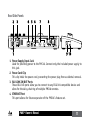
1
PMC
16
P e r s o n a l M o n i t o r C o n t ro l l e r
Owner’s Manual
ELECTROMAGNETIC COMPATIBILITY
This device complies with part 15 of the FCC Rules and
the Product Specifications noted on the Declaration
of Conformity. Operation is subject to the following
two conditions:
These symbols are internationally accepted symbols that warn of potential
hazards with electrical products. The lightning flash means that there are
dangerous voltages present within the unit. The exclamation point indicates that it is necessary for the user to refer to the owner’s manual.
These symbols warn that there are no user serviceable parts inside the
unit. Do not open the unit. Do not attempt to service the unit yourself.
Refer all servicing to qualified personnel. Opening the chassis for any
reason will void the manufacturer’s warranty. Do no get the unit wet. If
liquid is spilled on the unit, shut it off immediately and take it to a dealer
for service.
• this device may not cause harmful
interference, and
• this device must accept any interference received,
including interference that may cause undesired
operation.
Operation of this unit within significant
electromagnetic fields should be avoided.
• use only shielded interconnecting cables.
Disconnect the unit during storms to prevent damage.
If you want to dispose this product, do not mix it with general household waste. There is a
separate collection system for used electronic products in accordance with legislation that
requires proper treatment, recovery and recycling.
Private household in the 25 member states of the EU, in Switzerland and Norway may return their used
electronic products free of charge to designated collection facilities or to a retailer (if you purchase a similar
new one).
For Countries not mentioned above, please contact your local authorities for a correct method of disposal.
By doing so you will ensure that your disposed product undergoes the necessary treatment, recovery and
recycling and thus prevent potential negative effects on the environment and human health.
Warning
For your protection, read the following:
Important Safety Instructions
1. Read these instructions.
2. Keep these instructions.
3. Heed all warnings.
4. Do not use this apparatus near water.
5. Clean only with dry cloth.
6. Do not block any ventilation openings. Install in accordance with the manufacturer’s instructions.
7. Do not install near any heat sources such as radiators,
heat registers, stoves, or other apparatus (including
amplifiers) that produce heat.
8. Protect the power cord from being walked on or
pinched particularly at plugs, convenience receptacles,
and the point where they exit from the apparatus.
9. Unplug this apparatus during lightning storms or when
unused for long periods of time.
10. No user serviceable parts inside. Refer all servicing to
qualified service personnel. Servicing is required when
the apparatus has been damaged in any way, such as
power-supply cord or plug is damaged, liquid has been
spilled or objects have fallen into the apparatus, the
apparatus has been exposed to rain or moisture, does
not operate normally, or has been dropped.
11. WARNING: To reduce the risk of fire or electric
shock, do not expose this apparatus to rain or moisture.
12. Refer to labels on the unit, including bottom cover, or
other markings and pertinent information.
DECLARATION OF CONFORMITY
Manufacturer’s Name:
Manufacturer’s Address:
dbx
8760 S. Sandy Parkway
Sandy, Utah 84070, USA
declares that the product:
Product name:
Product option:
dbx PMC16
all (requires Class II power adapter that conforms to the requirements of EN60065, EN60742, or equivalent.)
conforms to the following Product Specifications:
Safety:
IEC 60065 -01+Amd 1
EMC:
EN 55022:2006
EN 55024:1998
FCC Part 15
Supplementary Information:
The product herewith complies with the requirements of the:
Low Voltage Directive 2006/95/EC
EMC Directive 2004/108/EC.
RoHS Directive 2002/95/EC
WEEE Directive 2002/96/EC
EC Regulation 278/2009
With regard to Directive 2005/32/EC and EC Regulation 1275/2008 of 17 December 2008, this product is designed, produced, and classified as Professional Audio Equipment and thus is exempt from this Directive.
Roger Johnsen
Director, Engineering
Signal Processing
8760 S. Sandy Parkway Sandy, Utah 84070, USA
Date: August 29, 2012
European Contact: Your local dbx Sales and Service Office or
Harman Signal Processing
8760 South Sandy Parkway
Sandy, Utah
84070 USA
Ph: (801) 566-8800
Fax: (801) 568-7583
Support/Service Contact
If you require technical support, contact dbx Technical Support. Be prepared to accurately describe
the problem. Know the serial number of your device–this is printed on a sticker attached to the
chassis. If you have not already taken the time to fill out your warranty registration card and send it
in, please do so now. You may also register online at www.dbxpro.com.
Before you return a product to the factory for service, we recommend you refer to the manual. Make
sure you have correctly followed installation steps and operation procedures. For further technical
assistance or service, please contact our Technical Support Department at (801) 568-7660 or visit
www.dbxpro.com. If you need to return a product to the factory for service, YOU MUST FIRST
CONTACT TECHNICAL SUPPORT TO OBTAIN A RETURN AUTHORIZATION NUMBER.
NO RETURNED PRODUCTS WILL BE ACCEPTED AT THE FACTORY WITHOUT A RETURN AUTHORIZATION
NUMBER.
Please refer to the Warranty information on the following page, which extends to the first end-user.
After expiration of the warranty, a reasonable charge will be made for parts, labor, and packing if you
choose to use the factory service facility. In all cases, you are responsible for transportation charges
to the factory. dbx will pay return shipping if the unit is still under warranty.
Use the original packing material if it is available. Mark the package with the name of the shipper
and with these words in red: DELICATE INSTRUMENT, FRAGILE! Insure the package properly. Ship
prepaid, NOT COLLECT. DO NOT SHIP PARCEL POST.
Warranty
1. The warranty registration card that accompanies this product must be mailed within 30 days after
purchase date to validate this warranty. You can also register online at www.dbxpro.com. Proof-ofpurchase is considered to be the responsibility of the consumer. A copy of the original purchase
receipt must be provided for any warranty service.
2. dbx warrants this product, when purchased new from an authorized U.S. dbx dealer and used solely
within the U.S., to be free from defects in materials and workmanship under normal use and service.
This warranty is valid to the original purchaser only and is non-transferable.
3. dbx liability under this warranty is limited to repairing or, at our discretion, replacing defective
materials that show evidence of defect, provided the product is returned to dbx WITH RETURN
AUTHORIZATION from the factory, where all parts and labor will be covered up to a period of two
years. A Return Authorization number must first be obtained from dbx. The company shall not be
liable for any consequential damage as a result of the product’s use in any circuit or assembly.
4. dbx reserves the right to make changes in design or make additions to or improvements upon this
product without incurring any obligation to install the same additions or improvements on products
previously manufactured.
5. The foregoing is in lieu of all other warranties, expressed or implied, and dbx neither assumes nor
authorizes any person to assume on its behalf any obligation or liability in connection with the sale
of this product. In no event shall dbx or its dealers be liable for special or consequential damages or
from any delay in the performance of this warranty due to causes beyond their control.
Table of Contents
Introduction ������������������������������������������������������������� 1
Philosophy ���������������������������������������������������������������� 2
Features ��������������������������������������������������������������������� 4
Package Contents ������������������������������������������������������ 5
Quick Start ���������������������������������������������������������������� 6
Panel Descriptions ���������������������������������������������������� 8
Top Panel���������������������������������������������������������������� 8
Rear/Side Panels�����������������������������������������������������11
Mic Stand Mounting Instructions ��������������������������� 13
Making Connections–Cabling ���������������������������������� 14
Power��������������������������������������������������������������������14
Analog Outputs�������������������������������������������������������14
Headphone Outputs�������������������������������������������������14
BLU link����������������������������������������������������������������15
Applications ������������������������������������������������������������ 16
Personal Monitoring w/dbx TR1616����������������������������16
Personal Monitoring w/BSS Audio Soundweb London
System������������������������������������������������������������������18
16 x 16 Digital Snake w/Personal Monitoring���������������20
32 x 32 Digital Snake w/Personal Monitoring���������������22
The LCD Display �������������������������������������������������������� 24
Introduction To The Meters Page�������������������������������24
Setup Mode–The Setup Wizard & Setup Menus ���������� 26
Setup Mode Introduction������������������������������������������26
The Setup Wizard����������������������������������������������������27
Setup Wizard Options�����������������������������������������������28
The Setup Menus�����������������������������������������������������30
Setup Menu Options �����������������������������������������������31
TOC
Live Mode–The PMC16 Monitor mixer ����������������������� 36
Live Mode Introduction��������������������������������������������36
Using Multi-Select���������������������������������������������������39
Using Groups����������������������������������������������������������40
Adjusting Channel Levels������������������������������������������41
Adjusting Channel Pans��������������������������������������������42
Adjusting Effect Sends���������������������������������������������43
Using The Solo Function�������������������������������������������44
Using The Mute Function������������������������������������������45
Using The Clear Function������������������������������������������46
Using The Global Trim Function���������������������������������47
The Top Panel Knobs ������������������������������������������������ 48
REVERB������������������������������������������������������������������48
LOW����������������������������������������������������������������������48
HIGH���������������������������������������������������������������������48
MASTER�����������������������������������������������������������������48
Presets ��������������������������������������������������������������������� 49
Storing & Recalling Presets���������������������������������������50
Factory Reset ����������������������������������������������������������� 52
Firmware Updates ���������������������������������������������������� 53
Block Diagram ��������������������������������������������������������� 54
Dimensions �������������������������������������������������������������� 56
Specifications ���������������������������������������������������������� 57
PMC16 Owner’s Manual
Introduction
Thank you for choosing the dbx© PMC16 personal monitor controller. The PMC16 is a digital
remote control providing a cost effective and powerful personal monitoring solution.
Whether using headphones, in-ear monitors, powered monitors, or traditional wedge
monitors, the PMC16 allows performing musicians to control their own personalized stage
monitor mix with ease.
Using BLU link, the PMC16 is capable of receiving up to 16 channels of high-end digital
audio via CAT5e cable. The PMC16 comprises a 16 channel monitor mixer section with full
control of levels, panning, effect send levels, muting, and soloing.
The PMC16’s output processing section includes: stereo width control, wedge monitor
compensation, high and low master EQ, master level control, and dbx limiting. Built-in
Lexicon© courtesy reverb rounds out the all-star processing power of the PMC16.
With a Setup Wizard for ease of configuration, full 16 channel monitor mixer level
metering, channel grouping, 16 preset locations for future recall of configurations and
mixes, and an intuitive yet powerful user interface, PMC16 gives you the power to dial in
YOUR mix exactly as YOU want it, in real time.
PMC16 Owner’s Manual
1
Philosophy
The PMC16 is a digital remote control consisting of a monitor mixer, a reverb effect
processor, and a global processing and output section. This creates an audio chain akin
to a traditional live sound monitoring system and puts it in the hands of the on-stage
musician, allowing each on-stage musician to tailor their own personalized mix and allow
the system engineer to focus on the front of house mix.
The PMC16 has two modes of operation: Setup Mode and Live Mode. Setup Mode refers to
the Setup Wizard and Setup Menus which are visible when the WIZARD button is pressed.
This mode is used by the system engineer to initially create the “configuration” and set
global options. Live Mode is the mode which refers to normal operation and consists of all
parameters pertaining to the “mix”. When the on-stage musician is editing their mix, they
are doing so in Live Mode. Live Mode consists of four pages, they are: the Meters page,
the Levels page, the Pan page, and the Effects page. Using these four pages allows each
musician to create their own unique mix by adjusting each instrument’s gain, placement
in the stereo field, and front to back spacial placement, using reverb. Channel muting and
soloing are available to help each musician focus on channels which require attention or
channels which should be eliminated from the mix.
The PMC16’s Setup Wizard assists the system engineer during setup and allows for quick,
easy configuration of the PMC16. The PMC16’s Live Mode of operation was designed to
provide a fast, intuitive navigational experience, so musicians new to the PMC16 can start
using the system immediately.
2
PMC16 Owner’s Manual
The PMC16 receives audio via the BLU link audio over Ethernet protocol. When assigning
BLU link audio channels to the PMC16, each PMC16 input channel can be assigned any
available BLU link channel on the network. This allows the system engineer to send any
BLU link audio channels on the network to any PMC16, so each musician receives the
channels of audio they require to create their mix.
The output processing in the PMC16 was designed to provide the best listening experience
possible. Stereo width control allows the system engineer to optimize the outputs for
wedge monitors, headphones, or in-ear monitoring. Stereo width is completely variable,
allowing for normal stereo operation, full mono collapse of the stereo image for mono
wedge monitors, hyper-stereo for use with headphones or stereo in-ear monitors, or
anything in between. Lexicon® courtesy reverb is provided to help the mix really come
to life!
The PMC16 was designed to provide all the outputs necessary for almost any application.
Two XLR outputs are available for connecting to amplifiers and powered wedge monitors.
Two 1/4” outputs allow for connection to any balanced or unbalanced line level device,
such as in-ear transmitters or recording devices. The 1/4” and 1/8” headphone outputs
ensure you won’t be stuck with headphones that aren’t compatible.
The on-board USB, DSC, and Ethernet ports allow the PMC16 to be built upon and exciting
new features to be added in the future, ensuring the PMC16 is prepared for what lies
ahead.
PMC16 Owner’s Manual
3
Features
•
•
•
•
•
•
•
•
•
•
•
•
•
•
•
•
4
16 Channel Monitor Mixer With Level, Pan, Mute, Solo, & Reverb Send Control
16 Preset Locations For Mix & Configuration Recall
LCD Display With 16 Channel Metering
Lexicon© Courtesy Reverb
dbx PeakStopPlus™ Limiting
Global High & Low EQ
Global Master Level Control
Global Stereo Width Control
BLU link High Bandwidth, Fault Tolerant Digital Audio Bus
XLR & 1/4” Stereo Or Mono Outputs
1/8” & 1/4” Headphone Outputs
Setup Wizard
Supports 48 kHz & 96 kHz Sampling Rates
Channel Linking, Grouping, & Multi-Select Capabilities
Supports Up To 60 PMC16s On A Single BLU link Ring
Built-In Sturdy Mic Stand Mount
PMC16 Owner’s Manual
Package Contents
The PMC16 was packaged with extreme care. Please take a moment to ensure the items
listed below were received and that no damage to contents has occurred.
• PMC16 Personal Monitor Controller
• Power Supply
• Manual
PMC16 Owner’s Manual
5
Quick Start
Configuration
1. Mount the PMC16 to a mic stand, if desired.
2. If connecting to a wedge monitor, turn off the power to the amplifier or powered
monitor.
3. Ensure the PMC16’s <MASTER> level control is turned all the way down (fully
counterclockwise).
4. Using the appropriate output connector, connect the PMC16 to the desired
monitoring device (i.e. headphones, in-ear monitor transmitter, amplifier, or
powered wedge monitor).
5. Connect the BLU link output of the sending BLU link device to the PMC16’s BLU
LINK IN port.
6. Connect the BLU LINK OUT port of the PMC16 to the next BLU link device in the
ring.
7. Connect the included power supply to the PMC16’s power input jack and the other
end to an available AC outlet.
8. Run the PMC16’s Setup Wizard by pressing the <WIZARD> button. Ensure “Setup”
Wizard” is selected on the display then press the <DATA> encoder to begin the
Wizard. Select the “RUN ALL SETUP ITEMS” option and press the <DATA> encoder.
9. Follow the on-screen instructions and select the appropriate options for your
system configuration.
6
PMC16 Owner’s Manual
10. When prompted, store the configuration to a preset. Follow the on-screen
instructions to name the preset and select a location in which to store the preset.
11. Once the Wizard is complete, press the <PRESET> button to return to Live mode.
12. Apply power to your amplifier or powered monitor.
13. Send signal to the PMC16 (signal presence can be verified on the PMC16’s LCD
display which displays all input level meters on the Meters page).
14. Slowly raise the PMC16’s <MASTER> level control to the initial desired listening
level.
Operation
15. Use the mute and solo functions to help create your mix, bringing channels into
focus using SOLO or eliminating channels from the mix using MUTE.
16. Adjust channel levels by using the <LEVELS> button, <CHANNEL SELECT> buttons,
and the <DATA> encoder.
17. Adjust channel pans by using the <PAN> button, <CHANNEL SELECT> buttons, and
the <DATA> encoder.
18. Turn the <REVERB> control to adjust how much overall reverb you would like in
the mix. If you would like to further adjust each channel’s reverb effect send level,
press the <EFFECTS> button and use the <CHANNEL SELECT> buttons for selecting
channels. Turn the <DATA> encoder to edit the selected effect send level(s).
19. If desired, save the mix to a preset by pressing the <PRESET> button and following
the on-screen instructions.
PMC16 Owner’s Manual
7
Panel Descriptions
Top Panel
1
2
3
4
5
6 7
8
9
10
11
12
1. LCD Display
This LCD display shows input metering, menus, pages, and parameters and is used
during configuration and operation.
2. DATA Encoder
The DATA encoder is used for navigating menus, on-screen option selection, and
parameter editing.
8
PMC16 Owner’s Manual
3. BACK Button
This button navigates back one page when navigating menus. This button also
navigates back to the Meters page when pressed multiple times (depending upon
how deep you are nested within a menu).
4. Function Buttons
• WIZARD Button–Pressing this button allows access to the PMC16 Setup Wizard
and Setup Menus for initially configuring the PMC16.
• GROUP Button–Toggles the Group function on and off.
• PRESET Button–Pressing this button allows for the storing or recalling of a
preset.
• LEVEL Button–Enters the Level page for adjusting each channel’s level.
• PAN Button–Enters the Pan page for adjusting each channel’s pan setting.
• EFFECTS Button–Enters the Effects page for adjusting each channel’s effect
send level.
5. REVERB Knob
This control allows for quick adjustment of the reverb’s return level, which adjusts
the overall reverb level.
6. LOW Knob
This control allows for quick adjustment of the low band shelving filter. This control
affects all outputs and is used to control the low-end frequencies of the mix.
PMC16 Owner’s Manual
9
7. HIGH Knob
This control allows for quick adjustment of the high band shelving filter. This
control affects all outputs and is used to control the high-end frequencies of the
mix.
8. MASTER Knob
This control allows for quick adjustment of the master output level. This control
affects all outputs and is pre-limiter.
9. Master Level Meter
This 4-segment LED meter displays the output signal level. The four LEDs represent
-30 dBu, 0 dBu, +10 dBu, and +17 dBu (3 dB below the clip point).
10. Channel Monitor Buttons
• CLEAR Button–Used to quickly clear all muted or soloed channels.
• SOLO Button–Used to solo channels or channel groups.
• MUTE Button–Used to mute channels or channel groups.
11. Scribble Strip
Use a non-permanent marker on this strip to label each channel.
12. Channel Select Buttons (1-16)
Allows for the selection of channels or channel groups for editing levels, pans,
effect sends, mutes, or solos. Dual LEDs on each button indicate channel selection
(top LED=green), solo state (bottom LED=amber), and mute state (bottom
LED=red).
10
PMC16 Owner’s Manual
Rear/Side Panels
2
3
4 5 6
7
8
9 10
1
1. Power Supply Input Jack
Used for providing power to the PMC16. Connect only the included power supply to
this jack.
2. Power Cord Clip
This clip holds the power cord, preventing the power plug from accidental removal.
3. BLU LINK IN/OUT Ports
These BLU link ports allow you to connect to any BLU link compatible device and
allow for the daisy chaining of multiple PMC16 remotes.
4. ETHERNET Port
This port allows for future expansion of the PMC16’s feature set.
PMC16 Owner’s Manual
11
5. DSC Input Port
This port allows for future expansion of the PMC16’s feature set.
6. USB Port
This Mini USB port is used for updating the PMC16’s firmware.
7. 1/4” Outputs
Connect these balanced outputs to any balanced or unbalanced line level device,
such as an in-ear transmitter or recording device.
8. XLR Outputs
Connect these balanced outputs to an amplifier or powered wedge monitor.
9. 1/4” Headphone Output
Connect this output to headphones which have a 1/4” headphone plug.
10. 1/8” Headphone Output
Connect this output to headphones which have a 1/8” mini headphone plug.
12
PMC16 Owner’s Manual
Mic Stand Mounting Instructions
To install the PMC16 to a mic stand:
1. Align the mounting hole on the bottom of the PMC16’s chassis to the threads
on the top of the mic stand.
2. Carefully turn the PMC16 clockwise to begin threading the PMC16 to the mic
stand, ensuring the threads are properly aligned. Be careful not to crossthread the threads or overtighten.
Note: The threaded mounting hole in the bottom of the PMC16 chassis is compatible
with 5/8” (1.6 cm) mic stand mounts.
PMC16 Owner’s Manual
13
Making Connections–Cabling
Power
Use only the included power supply for supplying power to the PMC16. A power supply
with the incorrect specifications may cause damage to the device. See “Specifications” for
further information on this power supply.
Analog Outputs
The 1/4” and XLR analog outputs provide
balanced audio connections. If connecting
to unbalanced equipment, use the 1/4”
outputs. The wiring conventions of these
connectors are shown to the right.
1/4”
XLR
Tip
Hot
Pin 1
Ground
Ring
Cold
Pin 2
Hot
Sleeve
Ground
Pin 3
Cold
The 1/4” and XLR output jacks can be used simultaneously as long as the
combined parallel load equals 400 Ω or greater.
Note:
Headphone Outputs
The 1/8” and 1/4” headphone outputs each have an impedance of 50 Ω. It is recommended
that headphones connected to these jacks have an impedance rating of 50 Ω or greater.
Note: The 1/8” and 1/4” headphone jacks are paralleled. Both connections can be used
simultaneously as long as the combined parallel load equals 50 Ω or greater.
14
PMC16 Owner’s Manual
BLU link
BLU link is a proprietary point to point networking protocol that requires CAT5e or better
cable. The BLU link ports are auto sensing, so you can use either a straight through
cable (same termination on both ends) or crossover cable between them. The maximum
allowable cable length of a single BLU link connection is 100 m (328 ft). By connecting
the last BLU link device in the ring, back to the first BLU link device in the ring, BLU
link’s built-in fault tolerance feature can be utilized. Any of the CAT5e cables shown in
the below table can be used when making BLU link connections.
TIA/EIA 568A
Straight Through
RJ-45
(8-Position)
TIA/EIA 568B
Straight Through
RJ-45
(8-Position)
1
1
Gr/Wh
Wh/Or
1
1
Wh/Or
Wh/Gr
1
Orange
2
2
Gr
Or
2
2
Or
Gr
2
3
White / Green
3
3
Wh/Or
Gr/Wh
3
3
Wh/Gr
Wh/Or
3
4
Blue
4
Bl
Wh/Br
4
Bl
Wh/Br
4
5
White / Blue
5
Wh/Bl
Br
5
Wh/Bl
Br
5
6
Green
6
Or
Gr
6
Gr
Or
6
7
White / Brown
7
7
Wh/Br
Bl
7
7
Wh/Br
Bl
7
8
Brown
8
8 Br
Wh/Bl
8
8 Br
Wh/Bl
8
RJ-45
(8-Position)
1
1
White / Orange
Green
2
2
3
White / Orange
3
4
Blue
5
White / Blue
6
Orange
7
White / Brown
8
Brown
White / Green
2
4
5
6
7
8
TIA/EIA 568B
Crossover
RJ-45
(8-Position)
RJ-45
(8-Position)
1
TIA/EIA 568A
Crossover
4
5
6
RJ-45
(8-Position)
4
5
6
RJ-45
(8-Position)
RJ-45
(8-Position)
For more information on BLU link, please visit www.dbxpro.com.
PMC16 Owner’s Manual
15
Applications
Personal Monitoring w/dbx TR1616
FRONT OF HOUSE
Mixer
Outputs
1
Receive Bank:
Transmit
Bank:11
Transmit
Bank:
1
Receive
Bank:
N/A
01
01
<--BLU link LOOP IN
BLU link LOOP OUT-->
TR1616
16
PMC16 Owner’s Manual
STAGE
<--To TR1616 LOOP IN
BLU link-->
Power Supply
PMC16 Owner’s Manual
BLU link OUT-->
RX: 1
PMC16
PMC16
PMC16
Power Supply
Powered
Wedge Monitor
IN
RX: 1
OUT
RX: 1
OUT
IN-->
BLU link
Powered
Wedge Monitor
IN
Powered
Wedge Monitor
BLU link-->
Power Supply
Legend
BLU link Connection
Analog Connection
17
Personal Monitoring w/BSS Audio Soundweb London System
BSS SOUNDWEB LONDON SYSTEM
<--BLU link IN
BLU link
OUT
BLU link
BLU-800
OUT
BLU-800
IN
Receive Bank: 1
Transmit Bank: 1
IN
BLU-800
18
BLU link OUT to PMC16 BLU link IN-->
PMC16 Owner’s Manual
STAGE
<--To BLU-800 BLU link IN
BLU link OUT-->
PMC16
PMC16
PMC16
BLU link-->
Power Supply
Powered
Wedge Monitor
IN
OUT
OUT
IN-->
BLU link
Powered
Wedge Monitor
IN
Powered
Wedge Monitor
Power Supply
PMC16 Owner’s Manual
BLU link-->
Power Supply
Legend
BLU link Connection
Analog Connection
19
FRONT OF HOUSE
1
From Instruments
On Stage
Transmit Bank: 1
Receive Bank: 2
01
SNAKE OUT-->
02
<--SNAKE IN
TR1616
20
PMC16 Owner’s Manual
BLU link to SNAKE IN (100 m/328 ft. max)
Mixer
Outputs
BLU link from SNAKE OUT (100 m/328 ft. max)
16 x 16 Digital Snake w/Personal Monitoring
STAGE
TR1616
2
<--SNAKE OUT
02
Transmit Bank: 2
Receive Bank: 1
01
<--BLU link LOOP IN
BLU link LOOP OUT to IN-->
Instruments
Powered
Wedge Monitor
Powered
Wedge Monitor
IN
OUT
OUT
RX: 1 or 2
IN
Instrument
Instrument
RX: 1 or 2
Powered
Wedge Monitor
Instrument
RX: 1 or 2
PMC16
PMC16
PMC16
BLU link-->
BLU link OUT to LOOP IN-->
SNAKE IN-->
BLU link-->
Legend
BLU link Connection
BLU link Snake Connection
Power Supply
Power Supply
PMC16 Owner’s Manual
Power Supply
Analog Connection
21
FRONT OF HOUSE
1
From Instruments
On Stage
Transmit Bank: 1
Receive Bank: 3
TR1616
01
03
From Instruments
On Stage
2
Transmit Bank: 2
Receive Bank: 4
02
04
TR1616
<--BLU link LOOP OUT to LOOP IN
BLU link LOOP OUT to LOOP IN-->
22
PMC16 Owner’s Manual
BLU link to SNAKE IN (100 m/328 ft. max)
Mixer
Outputs
BLU link from SNAKE OUT (100 m/328 ft. max)
32 x 32 Digital Snake w/Personal Monitoring
STAGE
BLU link LOOP OUT to LOOP IN
TR1616
Transmit Bank: 3
Receive Bank: 1
4
01
Powered
Wedge Monitor
Powered
Wedge Monitor
Powered
Wedge Monitor
Instrument
Instrument
RX: 1
OUT
OUT
RX: 1
02
Instruments
IN
BLU link LOOP OUT to IN-->
Instruments
04
Transmit Bank: 4
Receive Bank: 2
BLU link-->
RX: 1
PMC16
PMC16
PMC16
Instrument
BLU link-->
BLU link OUT to LOOP IN-->
3
<--SNAKE OUT
TR1616
03
IN
SNAKE IN-->
Legend
BLU link Connection
BLU link Snake Connection
Power Supply
Power Supply
PMC16 Owner’s Manual
Power Supply
Analog Connection
23
The LCD Display
Introduction To The Meters Page
The Meters page is the first page displayed on the LCD display after boot up and is
considered the “Home Page” of the PMC16. This page displays input level meters for all 16
input channels, offers details about which preset is currently loaded, and shows BLU link
cable connection status, BLU link network sample rate, and BLU link clock sync status.
1
24
2
3
1
Preset1
4
48k
I
O
PMC16 Owner’s Manual
5
6
1. Meters
These meters display input level for all 16 channels.
2. Preset Number
Displays the number of the currently loaded preset.
3. Preset Name
Displays the name of the currently loaded preset.
4. BLU link Sample Rate & Clock Sync Status
Displays the sample rate of the PMC16 and BLU link network. The Lock icon shows
when BLU link clock sync has been established (icon locked) and when clock sync
has not been established (icon unlocked). BLU link clock sync must be made before
audio can pass.
NOTE:
The PMC16 will automatically slave to the BLU link network sample rate.
5. BLU link Input Cable Connection Status
This icon shows whether or not a valid cable connection has been established at
the BLU LINK IN port.
6. BLU link Output Cable Connection Status
This icon shows whether or not a valid cable connection has been established at
the BLU LINK OUT port.
PMC16 Owner’s Manual
25
Setup Mode–The Setup Wizard & Setup Menus
Setup Mode Introduction
Setup Mode allows the system engineer to initially configure the PMC16 and consists of
the Setup Wizard and Setup Menus. It is accessed by pressing the <WIZARD> button.
Typically, the system engineer would run through the Setup Wizard first, in order to
select routing of BLU link audio channels to the PMC16, link stereo channels, name input
channels, create and name groups, and optimize outputs for the type of monitoring
system used.
Once configuration is complete, using the Setup Wizard, the system engineer will be
prompted to save the preset which contains the configuration created by the Setup Wizard.
If desired, the system engineer can then enter the Setup Menus to manually tweak the
configuration and set global system parameters. The edited preset can then be updated
(or re-stored). The PMC16 is now in Live Mode and ready for use by the on-stage musician.
26
PMC16 Owner’s Manual
The Setup Wizard
The Setup Wizard allows for quick and easy configuration of the PMC16.
To enter and navigate the Setup Wizard:
1. Press the <WIZARD> button.
2. Ensure “SETUP WIZARD” is selected in the LCD display. If it is not, turn the
<DATA> encoder to select it.
3. Press the <DATA> encoder to enter the Setup Wizard.
4. Once in the Setup Wizard, turning the <DATA> encoder allows you to select
available options on the display and pressing the <DATA> encoder allows you
to proceed with your selected option. Pressing the <BACK> button allows you
to back up one page in the navigational hierarchy.
5. Once all options have been set, according to the application, the Setup Wizard
will complete and prompt you to store the configuration to a preset. Simply
follow the on-screen instructions to store the preset.
6. Once the Setup Wizard is complete and the preset stored, press the <WIZARD>
button to return to Live mode.
NOTE:
To cancel and exit the Setup Wizard at any time, press the <WIZARD> button.
PMC16 Owner’s Manual
27
Setup Wizard Options
When using the Setup Wizard, the system engineer can either run through the entire
Setup Wizard or run through individual Wizard options. Typically, the “RUN ALL SETUP
ITEMS” option would be used to initially create a configuration. The other options would
be used when creating a new configuration with only minor changes, such as changing the
Reverb Type or Input Setup. The Setup Wizard consists of the following options:
RUN ALL SETUP ITEMS
This option allows you to run through the entire Setup Wizard, which consists of all
Setup Wizard options listed below. Use this option to initially configure the PMC16. When
selecting this option, you will receive a prompt allowing you to select which mixer settings
(i.e. levels, pans, and effect send levels) you would like to start with. The options are:
• CURRENT SETTINGS–Select this option to retain the mixer level, pan, and
effect send level settings of the currently loaded preset.
• DEFAULT SETTINGS–Select this option to set all mixer settings to the defaults,
which are: levels=0 dB, pans=center, and effect send levels=-6 dB.
• PRESET–Select this option to load the mixer level, pan, and effect send level
settings from another stored preset.
INPUT SETUP
This option allows you to route the desired BLU link channels to the PMC16’s inputs.
When selecting this option, you will receive a prompt allowing you to select between the
following options:
• TR1616–Select this option when all BLU link channels being fed to the PMC16’s
inputs will be coming from a single TR1616.
28
PMC16 Owner’s Manual
• OTHER–Select this option when you wish to independently route BLU link
channels to the PMC16 or select a range of consecutive BLU link channels for
routing to the PMC16.
CHANNEL SETUP
This option allows you to stereo link and name input channels.
GROUP SETUP
This option allows you to assign channels to groups and name groups.
REVERB SETUP
This option allows you to select the reverb type.
OUTPUT SETUP
This option allows you to select what type of monitoring device will be connected to the
PMC16 and whether you require a stereo or mono output configuration. This allows the
PMC16 to optimize its outputs for the application.
PMC16 Owner’s Manual
29
The Setup Menus
The Setup Menus allow the system engineer to manually edit individual elements of the
configuration and set global parameters and functions.
To enter and navigate the Setup Menus:
1. Press the <WIZARD> button.
2. Ensure “MENU” is selected in the LCD display. If it is not, turn the <DATA>
encoder to select it.
3. Press the <DATA> encoder to view the Setup Menus.
4. Turn the <DATA> encoder to select a Setup Menu.
5. Press the <DATA> encoder to view the selected Setup Menu.
6. Pressing the <DATA> encoder allows you to select on-screen options. Once an
on-screen option or parameter has been selected for editing, turn the <DATA>
encoder to change the value of the selected option or parameter.
7. Use the <BACK> button to navigate backwards and perform any other
necessary edits within the Setup Menus.
8. To exit the Setup Menus, press the <WIZARD> button.
30
PMC16 Owner’s Manual
Setup Menu Options
Many of the Setup menus contain parameters which are automatically set after running
and completing the Setup Wizard. These menus allow the system engineer to make manual
adjustments to the configuration and set the global parameters which dictate how the
PMC16 operates.
CHANNEL NAMES
This menu allows you to name each input channel. Names can be edited manually or
selected from a list. To manually name a channel, use the <DATA> encoder to select the
channel then follow the on-screen instructions. When finished, scroll to “Next” then press
the <DATA> encoder.
BLULINK CHANNEL ROUTING
This menu allows the system engineer to route the desired BLU link audio channels
to each of the PMC16’s inputs. Any available BLU link channel on the network can be
assigned to any of the PMC16’s inputs. Each PMC16 on the network is independently
assignable, allowing for unique combinations of channel assignments with each PMC16.
Note: BLU link channels 1-256 are available at 48 kHz and channels 1-128 are available
at 96 kHz.
STEREO LINKS
This menu allows for linking of adjacent channels (i.e. 1&2, 3&4, 5&6, 7&8, etc.).
Linking channels works well for instruments which contain a stereo signal and
are traditionally panned hard left and right, such as a drum machine or keyboard.
Note:
When channels are stereo linked, the channels’ pan behavior becomes a spread
PMC16 Owner’s Manual
31
control, providing variable control ranging from normal stereo to mono summed. Because
of this, a stereo linked channel pair cannot be mono summed and then panned left or
right of center.
GROUP NAMES
This menu allows you to name each group. Names can be edited manually or selected
from a list. To manually name a group, use the <DATA> encoder to select the group then
follow the on-screen instructions. When finished, scroll to “Next” then press the <DATA>
encoder.
GROUP ASSIGNMENTS
Groups are designed to allow the end user to manipulate multiple channels in unison. To
assign channels to groups, select the desired group by turning the <DATA> encoder then
press the <CHANNEL SELECT> button for each channel you wish to add to the group. The
top channel status LED on the Channel Select button will light green for each channel
added to the selected group. Repeat if you have other channels which require grouping.
NOTE: Channels can only be assigned to one group. When assigning groups, the top
channel status LED on the Channel Select button will light red for any channel which is
already assigned to another group.
REVERB TYPE
The PMC16’s reverb offers 5 Lexicon® reverb types. The available options in this menu are:
ROOM, SMALL PLATE, LARGE PLATE, SMALL HALL, and LARGE HALL. The wet/dry parameter
is fixed at 100% since the reverb is configured as a send/return effect in the signal path.
The overall amount of reverb effect can be adjusted using the REVERB control on the
PMC16’s top panel.
32
PMC16 Owner’s Manual
STEREO WIDTH
The Stereo Width parameter is automatically set when running and completing the Setup
Wizard. It can also be manually adjusted by the system engineer and can be used to create
a “hyper-stereo” image when monitoring with headphones or stereo in-ear monitors.
Stereo Width can also be used to mono sum outputs for use with mono wedge monitors or
in-ear monitors. The Stereo Width parameter affects all outputs.
LIMITER
The limiter provides speaker and hearing protection. This menu allows the system engineer
to manually adjust the Limiter Threshold. The Limiter Threshold parameter determines the
level at which limiting will begin to occur.
When configuring the PMC16 in the Setup Wizard, the limiter may be set automatically,
depending upon the options selected. Only adjust the limiter threshold manually if you
are sure you want to change the setting or if you need to calibrate the limiter for speaker
protection.
The PMC16’s limiter utilizes PeakStopPlus™ limiting, which is a two stage limiter. The
first stage of PeakStopPlus limiting is the Instantaneous Transient Clamp, which clamps
the signal with a soft logarithmic clamp function. This logarithmic function ensures that
the signal will not exceed the level set by the “Overshoot” parameter by more than the
overshoot amount. The PMC16’s “Overshoot” parameter is fixed at 6 dB. The second stage
is a unique program limiter featuring Intelligent Predictive Limiting. Its function is to
monitor the input signal and intelligently predict the amount of gain reduction required
to keep the output signal below the ceiling set by the Instantaneous Transient Clamp.
PMC16 Owner’s Manual
33
The limiter’s attack and release characteristics are program dependent, adapting to the
envelope as it changes. This provides a limiter which is very easy to set, yet offers very
musical results when used as intended.
Note: Since the PeakStopPlus™ limiter is a fail-safe limiter, it must come after the
MASTER output gain control in the signal path. This means that the limiter may act as a
“volume governor” if the limiter threshold is set too low and the MASTER volume set too
high. If this condition is met, a “pumping” or “breathing” artifact may be introduced,
causing an undesirable listening experience. To alleviate this condition, you must either
reduce the MASTER volume control or raise the limiter threshold. It is recommended
to lower the MASTER volume control if the undesirable artifacts can be eliminated and
the desired listening level maintained. If lowering the MASTER volume control does
not alleviate the problem, the limiter threshold must be raised. Only raise the limiter
threshold if the next device in the signal chain does not run the risk of being overdriven
or in-ear/headphone monitoring levels do not run the risk of getting too loud, potentially
causing hearing damage.
OUTPUT TYPE
This menu allows the system engineer to optimize the PMC16’s outputs for the type of
monitoring device used. The available options are: HEADPHONES, IN-EAR MONITORS, and
SPEAKER OR WEDGE. When the “SPEAKER OR WEDGE” option is selected, the PMC16’s
output compensation feature is activated. This feature helps protect wedge monitors from
woofer over excursion.
34
PMC16 Owner’s Manual
UTILITY
This menu allows the system engineer to set global parameters. The available options are:
• LCD CONTRAST: Adjusts the brightness of the LCD display.
• TIME OUT: When operating in Live Mode, this feature automatically returns
to the Meters page after a pre-determined time of inactivity. Time Out can be
configured in 1 minute increments (up to 10 minutes) or disabled.
INFO
This page displays the PMC16’s currently installed firmware version and IP address.
PMC16 Owner’s Manual
35
Live Mode–The PMC16 Monitor mixer
Live Mode Introduction
Live Mode is the normal operating mode of the PMC16 and is the mode in which the onstage musician (or end user) will be in when editing their monitor mix. Live Mode consists
of the four pages within the PMC16’s monitor mixer section, which are: the Meters page,
the Levels page, the Pan page, and the Effects page. These pages are shown in the
following pages of this manual.
When in Live Mode, the navigation and functionality of the PMC16 has been optimized to
provide extremely fast access to the PMC16’s monitor mixer parameters and fast selection
of channels for editing. This is accomplished by effectively creating Groups and using the
Multi-Select feature of the PMC16 (see “Using Multi-Select”). This workflow allows the
user to create their mix extremely efficiently and intuitively.
Mute and solo functions allow the user to focus on specific channels or remove unwanted
elements from the mix.
36
PMC16 Owner’s Manual
The PMC16 monitor mixer consists of the following four pages:
METERS PAGE
1
Preset1
48k
I
O
This is the first page visible on the
PMC16’s LCD display after boot up.
The Meters page allows you to see
the input level meters for all 16
input channels. The Meters page can
be accessed by pressing the <BACK>
button until the Meters page is
displayed.
LEVELS PAGE
MIXER
LEVELS
PMC16 Owner’s Manual
The Levels page allows you to adjust
each channel’s level. The Levels
page can be accessed by pressing
the <LEVEL> button. It can also be
accessed by pressing any <CHANNEL
SELECT> button from the Meters
page.
37
PAN PAGE
R
PAN
L
The Pan page allows you to adjust
each channel’s pan setting. The Pan
page can be accessed by pressing
the <PAN> button.
EFFECTS PAGE
EFFECT
LEVELS
38
The Effects page allows you to adjust
each channel’s effect send level. The
Effects page can be accessed by
pressing the <EFFECTS> button.
PMC16 Owner’s Manual
Using Multi-Select
The PMC16’s operation was designed to provide an efficient workflow. There is a feature
which was designed to allow the user to perform tasks on multiple channels as quickly
as possible. This feature is referred to as “Multi-Select”. Multi-Select is used during Live
Mode operation and allows for quick selection of multiple channels and/or groups for
multi-channel muting, soloing, or editing of channel levels, pans, or effect send levels.
To use Multi-Select:
1. Press and hold the <CHANNEL SELECT> button for the first channel or group
you would like to select.
2. With the first selected channel’s <CHANNEL SELECT> button still held down,
press and release the <CHANNEL SELECT> button for each additional channel
or group you would like to add to the multi-selection then release the
<CHANNEL SELECT> button which you have been holding.
3. Press the button for the desired function to edit (i.e. <LEVELS>, <MUTE>,
<PAN>, etc.).
4. Turn the <DATA> encoder to adjust the parameters for the selected channels/
groups respectively.
5. Press any <CHANNEL SELECT> button to dissolve the multi-selection.
Note: Relative values are retained unless a channel’s level, pan, or effect send level is
pushed beyond the maximum allowed value or below the minimum allowed value.
PMC16 Owner’s Manual
39
Using Groups
Groups are configured in Setup Mode and can be used to group multiple channels together,
allowing them to be controlled in unison. Pressing the <GROUP> button when in Live
Mode toggles the Group function on and off. When the Group function is enabled, the
GROUP button’s LED will light.
Groups are typically used to combine multiple channels of a single instrument or a stereo
pair which you want to retain individual control over. For example, you may want to group
two guitars together in order to give the end user the power to control the guitar channels
individually (GROUP button disabled) or as a stereo pair (GROUP button enabled). If these
guitar channels were stereo linked during setup, individual control of the two guitar
channels would not be possible by the end user.
Another example would be drums, which may consist of 8 channels: “Kick”, “Snare”, “Tom
1”, “Tom 2”, “Tom 3”, “Left Overhead”, “Right Overhead”, and “Hi-Hat”. By creating a
drum group during PMC16 configuration, all 8 drum channels can be assigned to a group.
With the Group button disabled, the musician monitoring through the PMC16 can adjust
the individual drum channels to create their initial drum mix. Once the individual monitor
mixer parameters have been set for each channel within the drum group, the user can
then enable the Group function to edit the drum channels’ parameters “as a whole”,
leaving the relationship between the respective drum channels’ parameters intact.
Note: When Group is enabled, it is possible to select multiple groups or select a
combination of groups and individual channels using the “Multi-Select” feature. When
Group is enabled, adjustment of stereo linked pan settings within a group is not supported.
40
PMC16 Owner’s Manual
Adjusting Channel Levels
The Levels page allows you to adjust each channel’s level.
To adjust a channel’s Level:
1. Press the <LEVEL> button. You should now be in the Level Edit page,
indicated by the LEVEL button LED lighting.
2. Select the channel(s) and/or group(s) which you would like to edit, using the
<CHANNEL SELECT> button(s) (the LED on the top of the selected Channel
Select button(s) will light green, indicating your selection).
3. Turn the <DATA> encoder to adjust the levels of all selected channels.
4. Repeat steps 2-3 to adjust the level(s) of any other channel(s).
To enable the Group function and adjust the levels of all
channels within a group respectively, press the <GROUP> button then perform the above
steps.
Activating Groups:
PMC16 Owner’s Manual
41
Adjusting Channel Pans
The Pan page allows you to adjust each channel’s pan setting.
To adjust a channel’s pan:
1. Press the <PAN> button. You should now be in the Pan Edit page, indicated by
the PAN button LED lighting.
2. Select the channel(s) and/or group(s) which you would like to edit, using the
<CHANNEL SELECT> button(s) (the LED on the top of the selected Channel
Select button(s) will light green, indicating your selection).
3. Turn the <DATA> encoder to adjust the selected channels’ pan settings.
4. Repeat steps 2-3 to adjust the pan(s) of any other channel(s).
Activating Groups: To enable the Group function to adjust the pans of all channels
within a group respectively, press the <GROUP> button then perform the above steps.
Note: When Group is enabled, adjustment of stereo linked pan settings within a group
is not supported.
42
PMC16 Owner’s Manual
Adjusting Effect Sends
The Effects page allows you to adjust each channel’s effect send level.
To adjust a channel’s effect send level:
1. Press the <EFFECTS> button. You should now be in the Effects Edit page,
indicated by the EFFECTS button LED lighting.
2. Select the channel(s) and/or group(s) which you would like to edit, using the
<CHANNEL SELECT> button(s) (the LED on the top of the selected Channel
Select button(s) will light green, indicating your selection).
3. Turn the <DATA> encoder to adjust the effect send levels of all selected
channels.
4. Repeat steps 2-3 to adjust the effect send level(s) of any other channel(s).
Activating Groups: To enable the Group function to adjust the effect send levels
of all channels within a group respectively, press the <GROUP> button then perform the
above steps.
PMC16 Owner’s Manual
43
Using The Solo Function
Soloing channels allows the user to focus on specific channels for editing. Solo states
are global and are not stored to presets. They are, however, retained after a power cycle.
To solo/unsolo channels:
1. Select the channel(s) and/or group(s) which you would like to solo, using the
<CHANNEL SELECT> button(s) (the LED on the top of the selected Channel
Select button(s) will light green, indicating your selection).
2. Press the <SOLO> button to solo the selected channel(s). The Status LED
on the bottom of the selected Channel Select button(s) will light amber,
indicating the channel is soloed.
3. Repeat steps 1-2 to solo additional channels, if necessary.
4. To unsolo channels, press the <CHANNEL SELECT> button(s) for the
channel(s) in which you would like to unsolo, then press the <SOLO> button.
To unsolo all channels quickly, use the Clear function.
Activating Groups: To enable the Group function and solo/unsolo all channels
within a group, press the <GROUP> button then perform the above steps.
Note: Multiple channels can be selected for soloing using the PMC16’s Multi-Select
feature (see “Using Multi-Select”). Conversely, the <SOLO> button can also be pressed
and held, allowing multiple channels to be quickly soloed using the channel’s <CHANNEL
SELECT> buttons.
44
PMC16 Owner’s Manual
Using The Mute Function
Muting channels allows the user to eliminate channels from the mix which they do not
want to hear. Mute states are global and are not stored to presets. They are, however,
retained after a power cycle.
To mute/unmute channels:
1. Select the channel(s) and/or group(s) which you would like to mute, using the
<CHANNEL SELECT> button(s) (the LED on the top of the selected Channel
Select button(s) will light green, indicating your selection).
2. Press the <MUTE> button to mute the selected channel(s). The Status LED on
the bottom of the selected Channel Select button(s) will light red, indicating
the channel is muted.
3. Repeat steps 1-2 to mute additional channels, if necessary.
4. To unmute channels, press the <CHANNEL SELECT> button(s) for the
channel(s) in which you would like to unmute, then press the <MUTE> button.
To unmute all channels quickly, use the Clear function.
Activating Groups: To enable the Group function and mute/unmute all channels
within a group, press the <GROUP> button then perform the above steps.
Note: Multiple channels can be selected for muting using the PMC16’s Multi-Select
feature (see “Using Multi-Select”). Conversely, the <MUTE> button can also be pressed
and held, allowing multiple channels to be quickly muted using the channel’s <CHANNEL
SELECT> buttons.
PMC16 Owner’s Manual
45
Using The Clear Function
The clear function allows all active mutes or solos to be cleared very quickly.
To clear all soloed channels:
1. Press the <CLEAR> button. The CLEAR, SOLO, and MUTE button LEDs will begin
flashing, indicating the clear function is ready to be performed.
2. Press the <SOLO> button to clear all soloed channels.
To clear all muted channels:
1. Press the <CLEAR> button. The CLEAR, SOLO, and MUTE button LEDs will begin
flashing, indicating the clear function is ready to be performed.
2. Press the <MUTE> button to clear all muted channels.
46
PMC16 Owner’s Manual
Using The Global Trim Function
The Global Trim function allows you to adjust the levels of all 16 channels in unison, while
retaining the level relationship between the channels. This is a very handy feature and
can be a tremendous time saver.
For example, let’s say you just completed your mix, but have just realized you’re not
hearing enough of the bass guitar. And let’s say the bass guitar’s channel level has been
maxed out. How can you turn up the bass guitar’s channel level if it’s maxed out? This
is a perfect scenario for using Global Trim. If this were to happen, Global Trim could be
used to lower all channel levels respectively. The bass guitar channel level could then be
raised, making it audible in the mix. If needed, the MASTER level control could then be
raised to make-up for the gain lost when lowering all channel gains.
To enable and disable Global Trim:
1. Press and hold the <LEVEL> button.
2. With the <LEVEL> button still held down, turn the <DATA> encoder to adjust
all channel levels respectively.
3. Release the <LEVEL> button to exit the Global Trim function.
Note: Relative values are retained unless a channel’s level parameter is pushed beyond
the maximum allowed value or below the minimum allowed value. Because of this, caution
should be taken to ensure you do not “undo” your mix. However, this feature can also be
used to quickly “zero-out” your mix levels by lowering the Global Trim level until all levels
are at the minimum value and then bringing the Global trim level back up.
PMC16 Owner’s Manual
47
The Top Panel Knobs
The four knobs on the top panel of the PMC16 provide quick access to the following PMC16
global parameters:
REVERB
This control allows for quick adjustment of the reverb’s return level, which affects the
overall reverb level. This control has a range of -120 dB to +6 dB and the knob’s twelve
o’clock position represents approximately -10 dB.
LOW
This control affects all outputs and is used to control the low-end frequencies of the
overall mix. The filter adjusted by this control is a low band shelving filter. This control
has a range of +/- 12 dB and the knob’s twelve o’clock position represents 0 dB.
HIGH
This control affects all outputs and is used to control the high-end frequencies of the
overall mix. The filter adjusted by this control is a high band shelving filter. This control
has a range of +/- 12 dB and the knob’s twelve o’clock position represents 0 dB.
MASTER
This control allows for quick adjustment of the master output level. This control affects all
outputs and is pre-limiter. This control has a range of -120 dBu to +6 dBu and the knob’s
twelve o’clock position represents approximately -10 dBu.
48
PMC16 Owner’s Manual
Presets
Presets allow for the storing of the “configuration” and the “mix”. All parameters which
are set after running the Setup Wizard and/or altered in the Setup Menus are the settings
which consist of the “configuration”. The “mix” parameters consist of the parameters set
by the end user when creating their mix (i.e. channel pans, channel levels, and channel
effect send levels). Up to 16 presets can be stored in the PMC16. Mute and solo states
are also not stored to presets (however, mute and solo states are retained after a power
cycle).
The following configuration options and parameters are stored to presets:
•
•
•
•
•
•
Channel Names
BLU link Channel Routing
Stereo Links
Group Names
Group Assignments
Reverb Type
PMC16 Owner’s Manual
•
•
•
•
•
•
Stereo Width
Limiter Threshold
Output Type
Channel Levels
Channel Pans
Channel Effect Send Levels
49
There are 3 options available when entering the Presets Menu. They are:
• OVERWRITE CURRENT PRESET–Use this option to quickly update the currently
loaded preset with any edits which have been made, storing the preset with the
same preset name and to the same preset location.
• STORE–Use this option to store the preset with a different preset name and/or
to change the preset location.
• RECALL–Use this option to recall a preset from memory.
Storing & Recalling Presets
NOTE: Press the <PRESET> button or repeatedly press the <BACK> button at any time
during the following procedures to cancel the operation and return to Live mode.
To overwrite the current preset:
1. Press the <PRESET> button.
2. Ensure the “OVERWRITE CURRENT PRESET” option is highlighted then press the
<DATA> encoder to select it.
3. Press the <DATA> encoder to verify that you would like to overwrite the
currently loaded preset.
4. The preset has now been overwritten.
50
PMC16 Owner’s Manual
To store a preset:
1. Press the <PRESET> button.
2. Turn the <DATA> encoder to highlight the “STORE” option then press the
<DATA> encoder to select it.
3. Follow the on-screen instructions to rename the preset.
4. Select “NEXT” on the LCD display then press the <DATA> encoder.
5. Select the desired preset location by either turning then pressing the <DATA>
encoder or by pressing the <CHANNEL SELECT> button that represents the
preset location you would like to store the preset to (i.e. button 1 for preset
1, button 2 for preset 2, etc.).
6. The preset has now been stored.
To recall a preset:
1. Press the <PRESET> button.
2. Turn the <DATA> encoder to highlight the “RECALL” option then press the
<DATA> encoder to select it.
3. Select the desired preset by either turning then pressing the <DATA> encoder
or by pressing the <CHANNEL SELECT> button that represents the preset you
would like to recall (i.e. button 1 for preset 1, button 2 for preset 2, etc.).
4. The preset has now been recalled.
PMC16 Owner’s Manual
51
Factory Reset
The PMC16 provides a factory reset function for resetting all parameters within the device
back to the factory default state.
WARNING! Performing the factory reset will permanently delete all stored user presets
from the PMC16.
To perform the Factory Reset procedure:
1. Press and hold the <PRESET> button while applying power to the PMC16. Wait
for the prompt to appear in the LCD display which instructs you to release the
<PRESET> button. Release the <PRESET> button.
2. Follow the on-screen instructions, pressing the <WIZARD> button to proceed
with the reset procedure or the <PRESET> button to cancel the operation.
52
PMC16 Owner’s Manual
Firmware Updates
The PMC16’s installed firmware version can be found on the bottom of the LCD display
during boot up or in the “INFO” Setup Menu. The firmware in the PMC16 is updatable via
the Mini USB port. Available firmware updates can be downloaded from www.dbxpro.com.
The Firmware Updater application for the PMC16 requires a Windows® PC.
To perform a firmware update:
1. Download the Firmware Updater application from www.dbxpro.com.
2. Follow the on-screen instructions to install the Firmware Updater application.
3. Launch the Firmware Updater application.
4. Follow the on-screen instructions to complete the firmware update procedure.
PMC16 Owner’s Manual
53
Block Diagram
54
PMC16 Owner’s Manual
PMC16 Owner’s Manual
55
Dimensions
9.742
.880
1.293
2.594
4.590
11.332
2.098
56
PMC16 Owner’s Manual
4.808
Specifications
Audio Performance
Frequency Response: Dynamic Range: THD+N: Crosstalk: BLU link Digital Audio Bus
Bit-Depth: Sample Rate: Connectors: Maximum Cable Length: Maximum Number of Nodes: Latency Per Node: Analog Outputs (XLR & 1/4”)
Maximum Output Level: Output Impedance: Headphone Outputs (1/8” & 1/4”)
Power/Impedance: Power
Adapter: Power Consumption:
Power Requirements: Weight/Dimensions
Product Weight:
Power Supply Weight:
Dimensions: +0/-0.2 dB 20 Hz – 20 kHz (Measured at 0 dBu output level)
>108 dB unweighted 22 Hz – 22 kHz bandwidth
>112 dB A-weighted
<.005% 20 Hz – 20 kHz (Measured at 0 dBu output level)
<97 dB 20 Hz – 20 kHz
24-bit
48 kHz or 96 kHz
2 x RJ45 Ethernet connectors
100 m/328 ft between devices (Category 5e cable)
60
4/Fs [0.08 ms @ 48 kHz, 0.04 ms @ 96 kHz]
20 dBu
40 Ω
900 mW per channel at 50 Ω (1/8” and 1/4” jacks are in parallel)
PS0920DC-01 (100-240 V AC, 50/60 Hz)
18 W
9 V DC 2.0 A
2.26 lb (1.03 kg)
0.31 lb (0.14 kg)
2 1/8” (H) x 11 5/16” (W) x 4 13/16” (D)
5.4 cm (H) x 28.7 cm (W) x 12.2 cm (D)
8760 South Sandy Parkway
Sandy, Utah 84070
PH (801) 566-8800
FAX (801) 566-7005
http://www.dbxpro.com
dbx® is a registered trademark
of Harman
Copyright - Harman
PMC16 Owner’s Manual 5035728-A
Printed in Malaysia