1
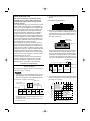
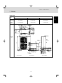
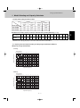
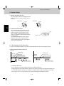
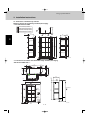
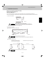
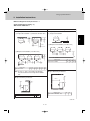
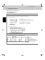
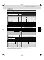
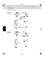
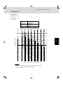
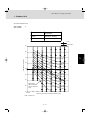
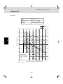
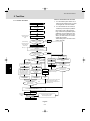
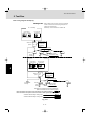
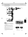
Design of Mini Multiset
4. Electrical Wiring
4-3. Wiring System Diagram
Indoor
unit (No. 1)
L
Power supply
220-240V 50Hz N
Outdoor unit
INV unit
1
3
Ground
Remote
controller
WHT 1
BLK 2
B
Power supply
220–240V-1N
50Hz
Ground
1
2
U2
D
L
N
C
U1
Ground
1
1
2
A
L
N
2
2
Ground
C
Indoor
unit (No. 2)
L
Power supply
220-240V 50Hz N
1
2
2
3
Ground
Remote
controller
WHT 1
BLK 2
B
U1
U2
D
1
1
2
2
Ground
C
Indoor
unit (No. 3)
Group control:
L
Power supply
220-240V 50Hz N
1
2
3
Ground
B
E
U1
U2
1
2
Ground
C
Indoor
unit (No. n)
L
Power supply
220-240V 50Hz N
1
2
3
Ground
Remote
controller
WHT 1
BLK 2
B
U1
U2
D
7P terminal board
1
1
2
2
Ground
NOTE
(1) Refer to Section 4-2. “Recommended Wire Length
and Wire Diameter for Power Supply System” for the
explanation of “A,” “B,” “C,” “D,” and “E,” in the above
diagram.
-- Type
(2) The basic connection diagram of the indoor unit
shows the 7P terminal board, so the terminal boards
in your equipment may differ from the diagram.
(3) Refrigerant Circuit (R.C.) address should be set
before turning the power on.
8P terminal board
1
(4) Regarding the R.C. address setting, refer to page 40
of the Installation Instructions. Auto. address setting
can be executed by remote controller automatically.
Refer to page 41~45 of the Installation Instructions.
2 - 34
U1 U2 R1 R2
Remote
Inter-unit
control wiring controller
1(L) 2(N)
Power
supply
2
U1
1(L)2(N)
Power
supply
U2
R1
5P terminal board
R2
R1 R2
Remote
controller
U1 U2
Inter-unit
control wiring
FC-ADS-SD-ASS-ACS
1
2
3
4
5
1(L)2(N) 4 5
Power
Inter-unit
supply control wiring
AWS Type