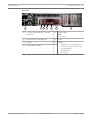
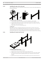
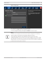
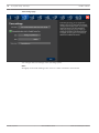
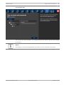
1
DIVAR IP 7000 2U
DIP-7080-00N, DIP-7082-8HD, DIP-7083-8HD
en
Quick Installation Guide
DIVAR IP 7000 2U
Table of Contents | en
3
Table of contents
1
Safety precautions
4
1.1
General safety precautions
4
1.2
Electrical safety precautions
5
1.3
ESD precautions
6
1.4
Operating precautions
6
1.5
Important notices
7
1.6
FCC and ICES compliance
7
2
System overview
3
System setup - hardware
10
3.1
Introduction
10
3.2
Unpacking the system
10
3.3
Preparing for setup
10
3.3.1
Choosing a setup location
10
3.3.2
Rack precautions
11
3.3.3
General system precautions
11
3.3.4
Rack mounting considerations
11
3.4
Rack mounting instructions
12
3.4.1
Separating the sections of the rack rails
12
3.4.2
Installing the inner rails
13
3.4.3
Installing the outer rails to the rack
14
3.4.4
Installing the chassis into the rack
14
3.4.5
Installing the chassis into a Telco rack
15
3.5
Turning on the system
15
4
System setup - first steps
16
4.1
Introduction
16
4.2
Setup instruction
16
4.3
Starting the application
16
4.4
Using Bosch VMS Configuration Wizard
17
4.5
Using Bosch VMS Configuration Client
28
4.5.1
Assigning device IP addresses
28
4.5.2
Adding additional licenses
29
4.6
Using Bosch VMS Operator Client
29
5
Additional documentation and client software
31
Bosch Sicherheitssysteme GmbH
8
Quick Installation Guide
2014.01 | V3 | DOC
4
en | Safety precautions
DIVAR IP 7000 2U
Safety precautions
1
Observe the safety precautions in this chapter.
1.1
General safety precautions
Follow these rules to ensure general safety:
–
Keep the area around the system clean and free of clutter.
–
Place the chassis top cover and any system components that have been removed away
from the system or on a table so that they won't accidentally be stepped on.
–
While working on the system, do not wear loose clothing such as neckties and
unbuttoned shirt sleeves, which can come into contact with electrical circuits or be
pulled into a cooling fan.
–
Remove any jewelry or metal objects from your body, which are excellent metal
conductors that can create short circuits and harm you if they come into contact with
printed circuit boards or areas where power is present.
–
After accessing the inside of the system, close the system back up and secure it to the
rack unit after ensuring that all connections have been made.
–
The system is heavy when fully loaded. When lifting the system, two people at either end
should lift slowly with their feet spread out to distribute the weight. Always keep your
back straight and lift with your legs.
Warning!
Interruption of mains supply:
!
Voltage is applied as soon as the mains plug is inserted into the mains socket.
However, for devices with a mains switch, the device is only ready for operation when the
mains switch (ON/OFF) is in the ON position. When the mains plug is pulled out of the
socket, the supply of power to the device is completely interrupted.
Warning!
Removing the housing:
!
To avoid electric shock, the housing must only be removed by qualified service personnel.
Before removing the housing, the plug must always be removed from the mains socket and
remain disconnected while the housing is removed. Servicing must only be carried out by
qualified service personnel. The user must not carry out any repairs.
Warning!
Power cable and AC adapter:
!
When installing the product, use the provided or designated connection cables, power cables
and AC adaptors. Using any other cables and adaptors could cause a malfunction or a fire.
Electrical Appliance and Material Safety Law prohibits the use of UL or CSA-certified cables
(that have UL/CSA shown on the code) for any other electrical devices.
2014.01 | V3 | DOC
Quick Installation Guide
Bosch Sicherheitssysteme GmbH
DIVAR IP 7000 2U
Safety precautions | en
5
Warning!
Lithium battery:
Batteries that have been inserted wrongly can cause an explosion. Always replace empty
!
batteries with batteries of the same type or a similar type recommended by the manufacturer.
Handle used batteries carefully. Do not damage the battery in any way. A damaged battery
may release hazardous materials into the environment.
Dispose of empty batteries according to the manufacturer's instructions.
Warning!
!
Handling of lead solder materials used in this product may expose you to lead, a chemical
known to the State of California to cause birth defects and other reproductive harm.
Notice!
Electrostatically sensitive device:
To avoid electrostatic discharges, the CMOS/MOSFET protection measures must be carried
out correctly.
When handling electrostatically sensitive printed circuits, grounded anti-static wrist bands
must be worn and the ESD safety precautions observed.
Notice!
Installation should only be carried out by qualified customer service personnel in accordance
with the applicable electrical regulations.
Disposal
Your Bosch product has been developed and manufactured using highquality materials and components that can be reused.
This symbol means that electronic and electrical devices that have reached
the end of their working life must be disposed of separately from
household waste.
In the EU, separate collecting systems are already in place for used
electrical and electronic products. Please dispose of these devices at your
local communal waste collection point or at a recycling center.
1.2
Electrical safety precautions
Basic electrical safety precautions should be followed to protect you from harm and the
system from damage:
–
Be aware of the locations of the power on/off switch on the chassis as well as the room's
emergency power-off switch, disconnection switch or electrical outlet. If an electrical
accident occurs, you can then quickly remove power from the system.
–
Do not work alone when working with high voltage components.
–
Power should always be disconnected from the system when removing or installing main
system components, such as the motherboard or memory modules. When disconnecting
power, you should first turn off the system and then unplug the power cords from all the
power supply modules in the system.
–
When working around exposed electrical circuits, another person who is familiar with the
power-off controls should be nearby to switch off the power if necessary.
Bosch Sicherheitssysteme GmbH
Quick Installation Guide
2014.01 | V3 | DOC
6
en | Safety precautions
–
DIVAR IP 7000 2U
Use only one hand when working with powered-on electrical equipment. This is to avoid
making a complete circuit, which will cause electrical shock. Use extreme caution when
using metal tools, which can easily damage any electrical components or circuit boards
they come into contact with.
–
The power supply power cords must include a grounding plug and must be plugged into
grounded electrical outlets. The unit has more than one power supply cord. Disconnect
both power supply cords before servicing to avoid electrical shock.
–
Mainboard replaceable soldered-in fuses: Self-resetting PTC (Positive Temperature
Coefficient) fuses on the mainboard must be replaced by trained service technicians only.
The new fuse must be the same or equivalent as the one replaced. Contact technical
support for details and support.
Caution!
Mainboard Battery: There is a danger of explosion if the onboard battery is installed upside
!
down, which will reverse its polarities. This battery must be replaced only with the same or
an equivalent type recommended by the manufacturer (CR2032). Dispose of used batteries
according to the manufacturer's instructions.
Caution!
!
DVD-ROM Laser: This system comes without a DVD-ROM drive but if added: To prevent direct
exposure to the laser beam and hazardous radiation exposure, do not open the enclosure or
use the unit in any unconventional way.
1.3
ESD precautions
Electrostatic Discharge (ESD) is generated by two objects with different electrical charges
coming into contact with each other. An electrical discharge is created to neutralize this
difference, which can damage electronic components and printed circuit boards. The
following measures are generally sufficient to neutralize this difference before contact is made
to protect your equipment from ESD:
–
Do not use mats designed to decrease electrostatic discharge as protection from
electrical shock. Instead, use rubber mats that have been specifically designed as
electrical insulators.
–
Use a grounded wrist strap designed to prevent static discharge.
–
Keep all components and printed circuit boards (PCBs) in their antistatic bags until ready
for use.
–
–
Touch a grounded metal object before removing the board from the antistatic bag.
Do not let components or printed circuit boards come into contact with your clothing,
which may retain a charge even if you are wearing a wrist strap.
–
Handle a board by its edges only. Do not touch its components, peripheral chips, memory
modules or contacts.
–
When handling chips or modules, avoid touching their pins.
–
Put the mainboard and peripherals back into their antistatic bags when not in use.
–
For grounding purposes, make sure your computer chassis provides excellent
conductivity between the power supply, the case, the mounting fasteners and the
mainboard.
1.4
Operating precautions
The chassis cover must be in place when the system is operating to assure proper cooling. Out
of warranty damage to the system can occur if this practice is not strictly followed.
2014.01 | V3 | DOC
Quick Installation Guide
Bosch Sicherheitssysteme GmbH
DIVAR IP 7000 2U
Safety precautions | en
7
Note:
Please handle used batteries carefully. Do not damage the battery in any way. A damaged
battery may release hazardous materials into the environment. Do not discard a used battery
in the garbage or a public landfill. Please comply with the regulations set up by your local
hazardous waste management agency to dispose of your used battery properly.
1.5
Important notices
Accessories - Do not place this unit on an unstable stand, tripod, bracket,
or mount. The unit may fall, causing serious injury and/or serious damage to
the unit. Use only with the cart, stand, tripod, bracket, or table specified by
the manufacturer. When a cart is used, use caution and care when moving
the cart/apparatus combination to avoid injury from tip-over. Quick stops,
excessive force, or uneven surfaces may cause the cart/unit combination to
overturn. Mount the unit per the manufacturer's instructions.
1.6
FCC and ICES compliance
(only for U.S.A. and Canada)
This equipment has been tested and found to comply with the limits for a Class A digital
device pursuant to Part 15 of the FCC Rules. These limits are designed to provide reasonable
protection against harmful interference when the equipment is operated in a commercial
environment. This equipment generates, uses, and can radiate radio frequency energy and, if
not installed and used in accordance with the manufacturer’s instruction manual, may cause
harmful interference with radio communications. Operation of this equipment in a residential
area is likely to cause harmful interference, in which case you will be required to correct the
interference at your own expense.
Bosch Sicherheitssysteme GmbH
Quick Installation Guide
2014.01 | V3 | DOC
8
en | System overview
2
DIVAR IP 7000 2U
System overview
DIVAR IP 7000 is an affordable, simple and reliable all-in-one recording, viewing and
management solution for network surveillance systems of up to 64 channels (with 32 channels
pre-licensed). Running the full Bosch VMS (Video Management System) solution and powered
by Bosch VRM (Video Recording Manager) software, the DIVAR IP 7000 is an intelligent IP
storage device that eliminates the need for separate NVR (Network Video Recorder) server and
storage hardware.
The 2U rack mount unit combines advanced management and state-of-the-art recording
management into a single cost-effective, plug and play IP recording appliance for IT-minded
customers which are seeking for a state-of-the-art “second generation” NVR recording
solution.
DIVAR IP 7000 features:
–
Instant real time access to video
View high quality HD video despite low or limited bandwidth connections. Dynamic
Transcoding technology ensures that you can view your video immediately — anytime,
anywhere.
–
Easy installation
DIVAR IP 7000 2U features wizard based set-up and centralized configuration to reduce
installation times. All components are pre-installed and pre-configured. Simply connect to
the network and turn on the unit — DIVAR IP 7000 2U starts recording straight out of the
box.
–
Access to Bosch VMS
After starting the system, immediate access to the Bosch VMS management application is
offered by a customized user interface. The ability to use one central user interface for
configuration and operation management reduces installation and training requirements,
and helps to keep ongoing system management costs low.
Front view:
2
1
2014.01 | V3 | DOC
3
4
1
Power Failure
5
Power
2
Overheat/Fan Fail
6
Reset
3
NIC1/NIC2
7
Power on/off
4
HDD
Quick Installation Guide
5
6
7
Bosch Sicherheitssysteme GmbH
DIVAR IP 7000 2U
System overview | en
9
Rear view:
2
1
1
3
4
5
2x mains connection 100 – 240 VAC,
7
6
5
50 - 60 Hz
Monitor (VGA)
Note:
Do not use!
2
2x PS/2 (mouse and keyboard)
6
2x NIC
3
2x USB
7
Slots for:
4
Serial interface COM1
–
1x graphic card (1x Display Port,
1x DVI) – DVI port must be used
for configuration
Bosch Sicherheitssysteme GmbH
Quick Installation Guide
–
1x sound card
–
2x USB 2.0
2014.01 | V3 | DOC
10
en | System setup - hardware
DIVAR IP 7000 2U
3
System setup - hardware
3.1
Introduction
Scope of delivery:
–
DIVAR IP 7000 – 8-bay system, fully equipped with 8 hard drives (DIP-7082-8HD)
–
In addition to the system itself, the following items should have been shipped along with
each system
3.2
–
One rackmount kit
–
One AC power cable for each power supply in the system
–
This quick install guide
Unpacking the system
You should inspect the box the chassis was shipped in and note if it was damaged in any way.
If the chassis itself shows damage, file a damage claim with the carrier who delivered it and
notify the respective Bosch RMA desk.
You will also need it placed near at least one grounded power outlet.
Due to the weight of the system: After opening the top of the shipping box, one person should
stand at either end and lift the disk array out together.
Be sure to read the safety precautions.
3.3
Preparing for setup
The box the system is shipped in includes a rack mount kit, which you will need to install the
system into the rack.
Follow the steps in the order given to complete the installation process in a minimum amount
of time. Read this section before you begin the installation procedure outlined in the sections
that follow.
3.3.1
Choosing a setup location
–
Situate the system in a clean, dust-free area that is well ventilated. Avoid areas where
heat, electrical noise and electromagnetic fields are generated. Place the system near a
grounded power outlet.
–
Leave approximately 25 inches clearance in front of the rack to be able to open the front
door completely.
–
Leave approximately 30 inches of clearance in the back of the rack to allow for sufficient
airflow and ease in servicing.
–
Install the system only in a Restricted Access Location (dedicated equipment rooms,
service closets and the like).
Notice!
This product is not suitable for use with visual display work place devices acccording to §2 of
the the German Ordinance for Work with Visual Display Units.
2014.01 | V3 | DOC
Quick Installation Guide
Bosch Sicherheitssysteme GmbH
DIVAR IP 7000 2U
3.3.2
System setup - hardware | en
11
Rack precautions
Warning!
!
To prevent bodily injury when mounting or servicing this unit in a rack, you must take special
precautions to ensure that the system remains stable. The following guidelines are provided
to ensure your safety:
–
Ensure that the leveling jacks on the bottom of the rack are fully extended to the floor
with the full weight of the rack resting on them.
–
In single rack installations, attach stabilizers to the rack.
–
If the rack is provided with stabilizing devices, install the stabilizers before mounting or
servicing the unit in the rack.
–
This unit should be mounted at the bottom of the rack if it is the only unit in the rack.
–
When mounting this unit in a partially filled rack, load the rack from the bottom to the top
with the heaviest component at the bottom of the rack.
–
In multiple rack installations, couple the racks together.
–
Always make sure the rack is stable before extending a component from the rack.
–
Extend only one component at a time - extending two or more simultaneously may cause
the rack to become unstable.
3.3.3
General system precautions
–
Review the electrical and general safety precautions that came with the components you
are adding to your chassis.
–
Determine the placement of each component in the rack before installing the rails.
–
Install the heaviest components on the bottom of the rack first, and then work up.
–
Use a regulating uninterruptible power supply (UPS) to protect the system from power
surges, voltage spikes if you want to keep your system operating in case of a power
failure.
–
Allow the SATA hard drives and power supply modules to cool before touching them.
–
Always keep the rack’s front door and all panels and components on the system closed
when not servicing to maintain proper cooling.
See also:
–
Safety precautions, page 4
3.3.4
Rack mounting considerations
Ambient operating temperature
If installed in a closed or multi-unit rack assembly, the ambient operating temperature of the
rack environment may be greater than the ambient temperature of the room. Therefore,
consideration should be given to installing the equipment in an environment compatible with
the manufacturer’s maximum rated ambient temperature (Tmra).
Reduced airflow
Equipment should be mounted into a rack so that the amount of airflow required for safe
operation is not compromised.
Mechanical loading
Equipment should be mounted into a rack so that a hazardous condition does not arise due to
uneven mechanical loading.
Bosch Sicherheitssysteme GmbH
Quick Installation Guide
2014.01 | V3 | DOC
12
en | System setup - hardware
DIVAR IP 7000 2U
Circuit overloading
Consideration should be given to the connection of the equipment to the power supply
circuitry and the effect that any possible overloading of circuits might have on overcurrent
protection and power supply wiring. Appropriate consideration of equipment nameplate
ratings should be used when addressing this concern.
Reliable ground
A reliable ground must be maintained at all times. To ensure this, the rack itself should be
grounded. Particular attention should be given to power supply connections other than the
direct connections to the branch circuit (i.e. the use of power strips, etc.).
3.4
Rack mounting instructions
This section provides information on installing the chassis into a rack unit. There are a variety
of rack units on the market, which may mean the assembly procedure will differ slightly. You
should also refer to the installation instructions that came with the rack unit you are using.
Notice!
This rail will fit a rack between 26" and 33.5" deep.
3.4.1
Separating the sections of the rack rails
The chassis package includes two rail assemblies in the rack mounting kit. Each assembly
consists of two sections:
–
an inner fixed chassis rail that secures directly to the chassis
–
an outer fixed rack rail that secures directly to the rack itself.
To separate the inner and outer rails:
1. Locate the rail assembly in the chassis packaging.
2.
2014.01 | V3 | DOC
Extend the rail assembly by pulling it outward.
Quick Installation Guide
Bosch Sicherheitssysteme GmbH
DIVAR IP 7000 2U
3.4.2
System setup - hardware | en
3.
Press the quick-release tab.
4.
Separate the inner rail extension from the outer rail assembly.
13
Installing the inner rails
The chassis includes a set of inner rails in two sections: inner rails and inner rail extensions.
The inner rails are pre-attached to the chassis, and do not interfere with normal use of the
chassis if you decide not to use a server rack. The inner rail extension is attached to the inner
rail to mount the chassis in the rack.
3
1
2
To install the inner rails:
1. Place the inner rail extensions on the side of the chassis aligning the hooks of the chassis
with the rail extension holes. Make sure the extension faces "outward" just like the preattached inner rail.
2.
Slide the extension toward the front of the chassis.
3.
Secure the chassis with 2 screws as illustrated.
4.
Repeat steps for the other inner rail extension.
Bosch Sicherheitssysteme GmbH
Quick Installation Guide
2014.01 | V3 | DOC
14
en | System setup - hardware
3.4.3
DIVAR IP 7000 2U
Installing the outer rails to the rack
Outer rails attach to the rack and hold the chassis in place. The outer rails extend between 30
inches and 33 inches.
3
1
2
To install the outer rails to the rack:
1. Secure the back end of the outer rail to the rack, using the screws provided.
2.
Press the button where the two outer rails are joined to retract the smaller outer rail.
3.
Hang the hooks of the rails onto the rack holes and if desired, use screws to secure the
front of the outer rail onto the rack.
4.
Repeat steps 1-3 for the remaining outer rail.
Locking Tabs
Both chassis rails have a locking tab, which serves two functions. The first is to lock the
system into place when installed and pushed fully into the rack, which is its normal position.
Secondly, these tabs also lock the system in place when fully extended from the rack. This
prevents the system from coming completely out of the rack when you pull it out for servicing.
3.4.4
Installing the chassis into the rack
To install the chassis into a rack:
1. Extend the outer rails as illustrated above.
2.
Align the inner rails of the chassis with the outer rails on the rack.
3.
Slide the inner rails into the outer rails, keeping the pressure even on both sides. When
the chassis has been pushed completely into the rack, it should click into the locked
position.
4.
2014.01 | V3 | DOC
Optional screws may be used to secure the to hold the front of the chassis to the rack.
Quick Installation Guide
Bosch Sicherheitssysteme GmbH
DIVAR IP 7000 2U
System setup - hardware | en
15
Warning!
!
Do not pick up the unit with the front handles. The handles are designed to pull the system
from a rack only.
Warning!
Stability hazard
!
Before sliding the unit out for servicing make sure that the rack stabilizing mechanism is in
place, or the rack is bolted to the floor. Failure to stabilize the rack can cause the rack to tip
over.
See also:
Rack precautions, page 11
3.4.5
Installing the chassis into a Telco rack
To install the chassis into a Telco type rack, use two L-shaped brackets on either side of the
chassis (four in total). First, determine how far the chassis will extend out the front of the
rack. Larger chassis should be positioned to balance the weight between front and back. If a
bezel is included on the chassis, remove it. Then attach the two front brackets to each side of
the chassis, then the two rear brackets positioned with just enough space to accommodate
the width of the Telco rack. Finish by sliding the chassis into the rack and tightening the
brackets to the rack.
3.5
Turning on the system
The last thing to be done is to provide input power to the system.
To turn on the system:
1. Plug the power cord from the power supply unit into a high-quality power strip that offers
protection from electrical noise and power surges. We recommended using an
uninterruptible power supply (UPS).
2.
Press the power button on the control panel to turn on the system.
Bosch Sicherheitssysteme GmbH
Quick Installation Guide
2014.01 | V3 | DOC
16
en | System setup - first steps
4
DIVAR IP 7000 2U
System setup - first steps
The following installation directive provides information on Installation and Configuration.
DIVAR IP systems are based on Windows Server 2008 R2 operating system.
This chapter is valid for DIVAR IP models that come with pre-installed hard drives. Empty units
start into the DOM recovery menu on first start. The recovery process and the RAID setup are
described in the installation manual.
See also:
–
Additional documentation and client software, page 31
4.1
Introduction
DIVAR IP systems are shipped with a pre-installed Configuration Wizard from factory.
4.2
Setup instruction
All DIVAR IP systems are preconfigured with a default IP address and with default iSCSI
settings.
–
IP Address: 192.168.0.200
–
Subnet mask: 255.255.255.0
Observe the following:
–
DIVAR IP needs to have an active network link during installation. Make sure that the
network switch you are connecting to is powered on.
–
The default IP address must not be occupied by any other device in the network. Make
sure that the default IP addresses of existing DIVAR IP systems in the network are
changed before adding another DIVAR IP.
–
Determine whether the initial installation is on a DHCP network. If not then you must
assign valid IP addresses to the video devices. Consult the local IT administrator to obtain
a valid IP address range to be used with DIVAR IP and associated devices.
–
The default iSCSI settings are optimized for use with Bosch VMS/VRM.
User with administrator rights:
–
User: BVRAdmin
–
Password: WSS4Bosch
Notice!
We strongly recommend not changing the user settings. Changing the user settings can result
in malfunctioning of the system.
4.3
Starting the application
DIVAR IP system is ready to go out of the box. The application provides a simple to install and
intuitive to use solution for network surveillance systems.
To start the application:
1. Connect the unit and the cameras to the network.
2.
Turn on the unit.
The Windows Server 2008 R2 setup process starts.
3.
Select the appropriate language for the installation, then click Next.
4.
In the Country or region, Time and currency and Keyboard layout lists, click the
appropriate item, then click Next.
The Microsoft Software License Terms and the EULA (End User License Agreement) are
displayed.
2014.01 | V3 | DOC
Quick Installation Guide
Bosch Sicherheitssysteme GmbH
DIVAR IP 7000 2U
System setup - first steps | en
17
5.
Accept the license terms, then click Start. Windows restarts.
6.
After restart is finished, press CTR+ALT+DELETE. The Windows logon page is displayed.
7.
Enter the default password WSS4Bosch.
8.
After entering the password, a message is displayed that you must change the password
before logging on the first time. To confirm, click OK.
9.
Change the password.
A series of scripts perform important setup tasks. This can take several minutes. Do not
turn off the computer.
The Bosch VMS default screen is displayed.
Note: In case of password loss a system recovery must be performed as described in the
installation manual. The configuration must be done from scratch or must be imported.
10. On the Bosch VMS default screen, double-click the Bosch VMS Wizard icon
to start
the Configuration Wizard.
The Welcome page is displayed.
11. Configure the system using the Configuration Wizard.
Notice!
If the IP addresses of devices that should be added don’t fall within the same IP range as the
DIVAR IP we recommend using the Bosch VMS Configuration Client. In all other cases use the
Configuration Wizard.
Notice!
To perform administrative tasks, the BVRAdmin account can be entered when Bosch VMS
default screen is displayed. To do so, press CTRL+ALT+DEL, then hold down SHIFT while
clicking the Switch User option and keep SHIFT pressed for about five seconds.
Notice!
We strongly recommend not changing any operating system settings. Changing operating
system settings can result in malfunctioning of the system.
See also:
–
Using Bosch VMS Configuration Wizard, page 17
4.4
–
Using Bosch VMS Configuration Client, page 28
–
Additional documentation and client software, page 31
Using Bosch VMS Configuration Wizard
Intended use for Configuration Wizard is the quick and easy configuration of a smaller system.
Configuration Wizard helps you to achieve a configured system including VRM, iSCSI system,
cameras, recording profiles and user groups.
User groups and their permissions are configured automatically. You can add or remove users
and set passwords.
Configuration Wizard can access Management Server only on the local computer.
You can save an activated configuration for backup purposes and import this configuration
later. You can change this imported configuration after import.
Configuration Wizard adds the local VRM automatically.
Restrictions:
The following tasks cannot be done with the Configuration Wizard. Use Bosch VMS
Configuration Client instead.
Bosch Sicherheitssysteme GmbH
Quick Installation Guide
2014.01 | V3 | DOC
18
en | System setup - first steps
DIVAR IP 7000 2U
–
adding additional license packages
–
adjusting schedules
–
configuring systems with no or multiple VRM
–
configuring external storage devices
–
adding Video Streaming Gateway
–
all advanced configurations beyond a basic setup (maps or alarms, for example)
For these tasks refer to the Bosch VMS manual (see Additional documentation and client
software, page 31).
To achieve a quick configuration using the Configuration Wizard:
1.
On the Bosch VMS default screen, double-click the Bosch VMS Wizard icon. The
Welcome page is displayed.
2.
Run-through the following pages of the wizard.
Welcome page
4
2014.01 | V3 | DOC
Click Next button to continue.
Quick Installation Guide
Bosch Sicherheitssysteme GmbH
DIVAR IP 7000 2U
System setup - first steps | en
19
Network settings page
You configure the network settings of the operating system.
As soon as you click Next button, the settings are activated.
If you have changed any setting on this page, click Reboot to restart the system.
Notice!
If a DHCP server is employed in the network for the dynamic assignment of IP addresses,
activate acceptance of IP addresses automatically assigned to the device.
Certain applications (VRM, Bosch Video Management System, Bosch Video Client,
Configuration Manager) use the IP address for the unique assignment of the device. If using
these applications, the DHCP server must support the fixed assignment between IP address
and MAC address, and must be appropriately set up so that, once an IP address is assigned, it
is retained each time the system is rebooted.
Bosch Sicherheitssysteme GmbH
Quick Installation Guide
2014.01 | V3 | DOC
20
en | System setup - first steps
DIVAR IP 7000 2U
Time settings page
You configure the time settings of the operating system.
Note:
We highly recommend defining a time server in a video surveillance environment.
2014.01 | V3 | DOC
Quick Installation Guide
Bosch Sicherheitssysteme GmbH
DIVAR IP 7000 2U
System setup - first steps | en
21
Video settings page
This page displays the devices and services that are included in the latest saved configuration.
You can import a configuration.
Note:
If the wizard fails in this step, close the wizard and start it again.
Bosch Sicherheitssysteme GmbH
Quick Installation Guide
2014.01 | V3 | DOC
22
en | System setup - first steps
DIVAR IP 7000 2U
Device selection page
Note:
The scan for devices can take a time. You can cancel the scan. All devices that were already
scanned, are displayed in the table.
This page displays all video devices that are not included in the latest saved configuration.
Deselect the devices that should not be added to the configuration, then click Next.
2014.01 | V3 | DOC
Quick Installation Guide
Bosch Sicherheitssysteme GmbH
DIVAR IP 7000 2U
System setup - first steps | en
23
Device authentication page
This page is used to authenticate at video devices protected by password. For easy
authentication with the same password for multiple devices you can use the clipboard (CTRL
+C, CTRL+V):
4
Select a row with a successfully authenticated device (green lock is displayed), press
CTRL+C, select multiple rows displaying a red lock and press CTRL+V).
Password check is performed automatically, when you do not enter a further character in the
password field for a few seconds or you click outside the password field.
Bosch Sicherheitssysteme GmbH
Quick Installation Guide
2014.01 | V3 | DOC
24
en | System setup - first steps
DIVAR IP 7000 2U
Recording profile page
For different profile assignments to different cameras you must execute Configuration Wizard
multiple times.
Note:
Before selecting a recording profile observe the following:
–
Recording profile details
All video devices use the default recording profile details.
To change these use the Bosch VMS Configuration Client.
–
Stream quality settings
All video devices use the default settings for Stream 1 to record.
To change these use the Bosch VMS Configuration Client.
–
2014.01 | V3 | DOC
Schedule
Quick Installation Guide
Bosch Sicherheitssysteme GmbH
DIVAR IP 7000 2U
System setup - first steps | en
25
The default schedule is used for all recording profiles.
The Day schedule is active from 8 a.m. until 6 p.m., Monday through Friday.
The Night schedule is active from 6 p.m. until 8 a.m., Monday through Friday.
The Weekend schedule is active 24 hours a day for Saturday and Sunday.
To change the schedule use the Bosch VMS Configuration Client.
Bosch Sicherheitssysteme GmbH
Quick Installation Guide
2014.01 | V3 | DOC
26
en | System setup - first steps
DIVAR IP 7000 2U
Add storage page
This page allows the addition of additional iSCSI storage devices
For limitations, refer to the datasheet available in the online catalog.
Notice!
If the wizard stops and the message appears, that the internal iSCSI storage is not ready for
recording because the LUNs are not formatted, you must format the LUNs using Bosch VMS
Configuration Client.
To format the LUNs, see Bosch VMS Configuration Manual, Chapter Formatting a LUN.
2014.01 | V3 | DOC
Quick Installation Guide
Bosch Sicherheitssysteme GmbH
DIVAR IP 7000 2U
System setup - first steps | en
27
User accounts page
You can add users and passwords. Use Configuration Client to add user groups and to change
permissions.
Notice!
We strongly recommend using password protection for all users defined in the system.
Bosch Sicherheitssysteme GmbH
Quick Installation Guide
2014.01 | V3 | DOC
28
en | System setup - first steps
DIVAR IP 7000 2U
Finish configuration page
This page is used for providing a global default password for all devices that are not currently
protected by a password.
After clicking Save and activate the configuration is activated.
After successful activation the Activate Configuration page is displayed again. Now you can
store a backup of the configuration if desired: Click Save backup copy.
Notice!
We recommend saving the configuration after each change on an external storage media, for
example, USB drive. After recovering the system you can import this backup copy.
4.5
4.5.1
Using Bosch VMS Configuration Client
Assigning device IP addresses
If the IP addresses of devices that should be added do not fall within the same IP range as the
DIVAR IP, we recommend using the Bosch VMS Configuration Client.
To assign device IP addresses:
1.
On the Bosch VMS default screen, double-click the Configuration Client icon
to
change device network settings. The application starts.
2.
Enter the following, then click OK.
User name: admin
Password: no password required (if not set with the wizard)
Connection: 127.0.0.1
3.
On the Hardware menu, click Initial Device Scan.
The application performs a network scan for all defaulted devices.
4.
To assign all devices at once, click Select All, then right-click the selected devices, then
click SetIP Addresses. The Set IP Addresses dialog box is displayed.
2014.01 | V3 | DOC
Quick Installation Guide
Bosch Sicherheitssysteme GmbH
DIVAR IP 7000 2U
System setup - first steps | en
29
Note:
It is also possible to configure the devices individually with specific IP addresses based
on MAC address.
5.
Enter the starting IP address for the address range you want to use, click the Calculate
6.
To restart the devices, click OK.
7.
Close Configuration Client .
tab, then click OK.
4.5.2
Adding additional licenses
You can add additional licenses using Configuration Client.
To activate the software:
1.
2.
Start Configuration Client.
On the Tools menu, click License Manager....
The License Manager dialog box is displayed.
3.
Click to check the boxes for the software package, the features, and the expansions that
you want to activate. For the expansions, enter the number of licenses.
If you have received a Bundle Information file, click Import Bundle Info to import it.
4.
Click Activate.
The License Activation dialog box is displayed.
5.
Write down the computer signature or copy and paste it into a text file.
6.
On a computer with Internet access, enter the following URL into your browser:
https://activation.boschsecurity.com
If you do not have an account to access the Bosch License Activation Center, either
create a new account (recommended) or click the link to activate a new license without
logging on. If you create an account and log on before activating, the License Manager
keeps track of your activations. You can then review this at any time.
Follow the instructions to obtain the License Activation Key.
7.
Return to the Bosch VMS software. In the License Activation dialog box, type the License
Activation Key obtained from the License Manager and click Activate.
The software package is activated.
4.6
Using Bosch VMS Operator Client
Use Bosch VMS Operator Client to verify the live, recording and playback functionality of
DIVAR IP.
To verify live image functionality in the Operator Client
1.
On the Bosch VMS default screen, double-click the Operator Client icon
. The
application starts.
2.
Enter the following and click OK.
User name: admin
Password: no password required (if not set with the wizard)
Connection: 127.0.0.1
3.
Click the live image icon. The Logical Tree with the cameras is displayed.
4.
Select a camera and drag it to an image window. The image of the camera is displayed if
the camera is assigned correctly.
Note:
Cameras in the image window with a red dot in the camera’s icon are viewed live.
To verify recording functionality in the Operator Client
4 Cameras in the Logical Tree with a red dot in the camera’s icon are recording.
Bosch Sicherheitssysteme GmbH
Quick Installation Guide
2014.01 | V3 | DOC
30
en | System setup - first steps
DIVAR IP 7000 2U
To verify playback functionality in the Operator Client
4 The time line moves if the a camera is viewed in playback mode.
To perform further functionalities refer to the Bosch VMS manual.
Performance overview live
4CIF
Number of software
2.5 Mbit
5 Mbit
10 Mbit
20
13
9
monitors
720p
Number of software
2.5 Mbit
5 Mbit
10 Mbit
14
11
6
monitors
1080p
Number of software
2.5 Mbit
5 Mbit
10 Mbit
8
6
5
monitors
References to the manual are described in Additional documentation and client software, page
31.
2014.01 | V3 | DOC
Quick Installation Guide
Bosch Sicherheitssysteme GmbH
DIVAR IP 7000 2U
5
Additional documentation and client software | en
31
Additional documentation and client software
Documentation for Bosch Security System products can be found as follows:
4 www.boschsecurity.com > select your region and your country > select Product Catalog >
start a search for your product > select the product in the search results to show the
existing documents.
And on the following network share:
4
\\<IP address of DIVAR IP>\sources
Bosch Sicherheitssysteme GmbH
Quick Installation Guide
2014.01 | V3 | DOC
Bosch Sicherheitssysteme GmbH
Robert-Bosch-Ring 5
85630 Grasbrunn
Germany
www.boschsecurity.com
© Bosch Sicherheitssysteme GmbH, 2014