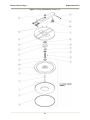
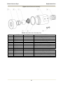
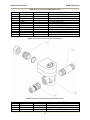
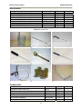
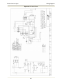
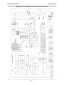
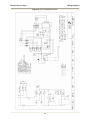
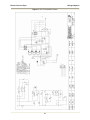
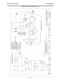
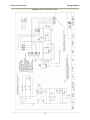
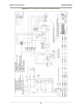
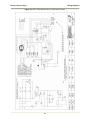
1
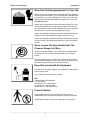
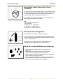
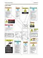
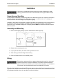
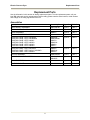
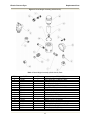
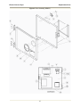
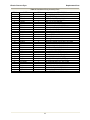
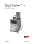
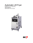
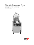
Electric Pressure Fryer
MODELS LPF, LPF-F, & LPF-FC
Service Manual
Serial Numbers 126660 and higher
Warranty Information
LIMITED ONE YEAR WARRANTY
BKI (The "Company") warrants to the original purchaser that at time of shipment from the Company
factory, this equipment will be free from defect in materials and workmanship. Written notice of a claim
under this warranty must be received by the Company within ONE YEAR from the date of installation, but
no longer than ONE YEAR AND THREE MONTHS from date of shipment from the factory. Defective
conditions caused by abnormal use or misuse, lack of or improper maintenance, damage by third parties,
alterations by unauthorized personnel, acts of God, failure to follow installation and/or operating
instructions, or any other events beyond the reasonable control of the Company will NOT be covered
under this warranty. The obligation of the Company under this warranty shall be limited to repairing or
replacing (at the option of the Company) any part, with the exception of lamps, fuses, and glass (which
are not covered under warranty), which is found defective in the reasonable opinion of the Company. Any
part found defective by the Company will be repaired or replaced without charge F.O.B. factory,
Simpsonville, South Carolina or F.O.B. authorized BKI Distributor. The Company and/or its authorized
representatives will assume the normal replacement labor expense for the defective part for the period of
the warranty as stated above, excluding travel and/or other expenses incidental to the replacement of the
defective part, where replacement work is performed during standard business hours and not subject to
overtime, holiday rates, and/or any additional fees. IN NO EVENT SHALL THE COMPANY BE LIABLE
FOR LOSS OF USE, LOSS OF REVENUE OR LOSS OF PRODUCT OR PROFIT OR FOR INDIRECT
OR CONSEQUENTIAL DAMAGES INCLUDING BUT NOT LIMITED TO, FOOD SPOILAGE OR
PRODUCT LOSS. WARRANTY DOES NOT COVER GLASS BREAKAGE. THE ABOVE WARRANTY IS
EXCLUSIVE AND ALL OTHER WARRANTIES, EXPRESS OR IMPLIED, ARE EXCLUDED INCLUDING
THE IMPLIED WARRANTIES OF MERCHANTABILITY AND FITNESS FOR A PARTICULAR
PURPOSE.
REPLACEMENT PARTS
Any appliance replacement part, with the exception of lamps, fuses, and glass, which proves to be
defective in material or workmanship within ninety (90) days of installation will be replaced without charge
F.O.B. Factory, Simpsonville, SC or F.O.B. authorized BKI Distributor. The user shall have the
responsibility and expense of removing and returning the defective part to the Company as well as the
cost of reinstalling the replacement or repaired part.
Electric Pressure Fryer
Table of Contents
Table of Contents
Table of Contents........................................................................................................................................ 1
Introduction ................................................................................................................................................. 2
Safety Precautions.................................................................................................................................... 2
Safety Signs and Messages................................................................................................................. 2
Specific Precautions ............................................................................................................................. 3
Equipotential ground plane .............................................................................................................. 3
Full Disconnection............................................................................................................................ 3
Safe Work Practices ............................................................................................................................. 4
Safety Labels........................................................................................................................................ 8
Installation ................................................................................................................................................... 9
Unpacking and Handling........................................................................................................................... 9
Assembly and Mounting ........................................................................................................................... 9
Wiring........................................................................................................................................................ 9
Initial Test and Adjustment ..................................................................................................................... 10
Replacement Parts.................................................................................................................................... 11
Assemblies.............................................................................................................................................. 11
Accessories............................................................................................................................................. 31
Components............................................................................................................................................ 31
Wiring Diagrams........................................................................................................................................ 34
Notes .......................................................................................................................................................... 47
1
Electric Pressure Fryer
Introduction
Introduction
The LPF Pressure Fryer is compact, attractive and functional in design. It is constructed of a stainless
steel fryer pot for cleaning ease. Exclusive BKI patented features and safety devices offer flexibility,
efficiency and reliability plus PERFECTION IN PRESSURE FRYING!
The BKI name and trademark on this unit assures you of the finest in design and engineering -- that it has
been built with care and dedication -- using the best materials available. Attention to the operating
instructions regarding proper installation, operation, and maintenance will result in long lasting
dependability to insure the highest profitable return on your investment.
PLEASE READ THIS ENTIRE MANUAL BEFORE OPERATING THE UNIT. If
you have any questions, please contact your BKI Distributor. If they are unable to
answer your questions, contact the BKI Technical Service Department, toll free:
1-800-927-6887. Outside the U.S., call 1-864-963-3471.
Safety Precautions
Always follow recommended safety precautions listed in this manual. Below is the safety alert symbol.
When you see this symbol on your equipment, be alert to the potential for personal injury or property
damage.
Safety Signs and Messages
The following Safety signs and messages are placed in this manual to provide instructions and identify
specific areas where potential hazards exist and special precautions should be taken. Know and
understand the meaning of these instructions, signs, and messages. Damage to the equipment, death or
serious injury to you or other persons may result if these messages are not followed.
This message indicates an imminently hazardous situation which, if not avoided,
will result in death or serious injury.
This message indicates a potentially hazardous situation, which, if not avoided,
could result in death or serious injury.
This message indicates a potentially hazardous situation, which, if not avoided,
may result in minor or moderate injury. It may also be used to alert against
unsafe practices.
This message is used when special information, instructions or identification are
required relating to procedures, equipment, tools, capacities and other special
data.
2
Electric Pressure Fryer
Introduction
Specific Precautions
Lids for LPF Pressure Fryers manufactured prior to May 27, 1980 (or units with
serial numbers lower than 3613) could be manually opened while under pressure
resulting in serious injury or death. If you have one of these units, please contact
the BKI Technical Services Department toll-free at 1-800-927-6887 for urgent
update information.
Risk of fire exists if the oil level drops below 5mm of the maximum oil level.
Use of oil/shortening older than the manufacturers recommendations for life of
the oil is prone to surge boiling and flash fires. Follow the oil manufacturers
guidelines for the life cycle of oil/shortening.
Do not open the drain valve or the fill valve while the fryer is under pressure.
Serious burns may result.
Follow instructions regarding effects of surge boiling of over-wet foods and
proper load size.
For non-European models, this unit incorporates components that contain
Mercury. The use of Mercury relays is an industry standard.
Equipotential ground plane
When a high current flows through a conductor, differences in potential appear
between the conductor and nearby metallic surfaces near the appliance. As a
result, sparks may be produced between the appliance and surrounding metal
surfaces. These sparks could cause serious injury, damage, or fire.
BKI provides an Equipotential ground terminal for the connection of a bonding
conductor after the installation of the appliance per lEC60417-1. This terminal is
located on the inside of the Power Entry Supply box near the Earth connection
and is marked with this symbol.
Full Disconnection
In accordance with Local and/or National wiring codes, the installer must provide
a means of full disconnection under over voltage Category III conditions. An IEC
approved cord and plug combination will meet this requirement.
Units not provided with a cord and plug do not meet this requirement. In
accordance with Local and/or National wiring codes, the installer must provide
the means of full disconnection.
The fryer is designed to hold a maximum of 48lbs (21.8KG) of oil/shortening.
3
Electric Pressure Fryer
Introduction
Safe Work Practices
Noncombustible Floors Only
Make sure your floor is noncombustible. Do not operate your fryer
on floors that are wood, carpeted or have rubber mats.
•
Placing your fryer on a combustible floor could cause a fire.
Serious injury could result.
•
Examples of noncombustible floors where you can safely
place your fryer are concrete, tile, and ceramic.
Keep The Area Around Your Fryer
Uncluttered
Make sure to keep the area around your fryer clear of any
obstacles.
Serious injury can occur if you trip or fall near the fryer. You could
be burned by hot shortening that splashes out of the fryer or by
falling against the hot metal of the fryer.
Keep The Floor Around Your Fryer Clean Of
Shortening
Make sure to keep the floor around your fryer clean of shortening
and other liquids.
Serious injury can occur if you slip near your fryer. You could be
burned by hot shortening that splashes out of the fryer or by falling
against the hot metal of the fryer.
Keep The Lid Closed When The Fryer Is Not
In Use
Hot shortening can splash if someone moves the fryer or bumps
into it. Serious injury can occur if hot shortening splashes out of the
fryer.
Do not lean, sit or stand on the fryer or perform any maintenance or
cleaning duties while the fryer or the shortening is hot. You could
be burned.
Keep The Casters Locked
To avoid spilling shortening, keep the casters locked. If any
shortening spills near your fryer, clean it up immediately.
4
Electric Pressure Fryer
Introduction
Do Not Overfill The Fryer With Shortening
Hot shortening and steam may escape and burn you if you put too
much shortening in the fryer. Fill the fryer to approximately one inch
below the fill marks that are inside the fryer pot. Heat the
shortening. If needed, carefully add more shortening to bring the
level to the fill marks.
Do Not Let Any Water Get Into The Fryer
Always remove excess moisture from food before placing it into the
fryer basket. Water will cause the hot shortening to spatter. You
could be burned.
Do Not Overload The Basket With Food
Hot shortening and steam may escape and burn you if you place
too much food in the basket.
Always Make Sure The Lid Hook Is Latched
When Closing The Fryer
To make sure the lid hook is latched properly, press down the lid
until the hook snaps shut. Hot shortening and steam can escape if
the lid hook is not latched properly. You could be burned.
Keep Away From The Vent
Hot steam escapes from the vent continuously when you are using
your fryer. You could be burned if you get too close to the vent.
Seal The Safety Valve Properly
To seal the safety valve, lift the arm on the side of the valve. Then
release it. The valve should snap closed. Hot steam can escape
from the valve and you could be burned if you do not seal the valve
properly.
Always Tighten The Spin Handle When
Closing The Fryer
Hot shortening and steam can escape if you do not tighten the spin
handle properly. You could be burned. Line up the orange knobs on
the fryer lid handle and the front hook when tightening.
Do Not Over-Tighten The Spin Handle
You could damage the fryer.
5
Electric Pressure Fryer
Introduction
Wear Safe Clothing Appropriate To Your Job
Always wear your insulated mitts when handling the fryer basket or
touch any hot metal surfaces. You received a pair of insulated mitts
with your fryer. If you lose or damage your mitts, you can buy new
ones at your local restaurant equipment supply store or from your
local BKI Distributor.
Always wear non-skid shoes when working around the fryer or any
other equipment that uses shortening. Never wear loose clothing
such as neckties or scarves while operating your fryer. Keep loose
hair tied back or in a hair net while operating your fryer.
Always wear appropriate personal protection equipment during the
filtering process to guard against possible injury from hot oil.
Always wear appropriate personal protection equipment during the
boil-out process to guard against possible injury from hot cleaning
solution.
Never Loosen The Spin Handle Until The
Pressure Gauge Is At Zero
Steam may escape suddenly if you loosen the spin handle before
the gauge is at zero. If steam escapes suddenly, you could be
burned.
After the pressure gauge is at zero, wait 5 seconds. Then loosen
the spin handle slowly to open the lid of the fryer. By doing this, the
steam will escape slowly and you will not be burned.
Keep this manual with the Equipment
This manual is an important part of your equipment. Always keep it
near for easy access.
If you need to replace this manual, contact:
BKI
Technical Services Department
P.O. Box 80400
Simpsonville, S.C. 29680-0400
Or call toll free: 1-800-927-6887
Outside the U.S., call 864-963-3471
Protect Children
Keep children away from this equipment. Children may not
understand that this equipment is dangerous for them and others.
NEVER allow children to play near or operate your equipment.
6
Electric Pressure Fryer
Introduction
Keep Safety Labels Clean and in Good
Condition
Do not remove or cover any safety labels on your equipment. Keep
all safety labels clean and in good condition. Replace any damaged
or missing safety labels. Refer to the Safety Labels section for
illustration and location of safety labels on this unit.
If you need a new safety label, obtain the number of the specific
label illustrated on page 8, then contact:
BKI
Technical Services Department
P.O. Box 80400
Simpsonville, S.C. 29680-0400
Or call toll free: 1-800-927-6887
Outside the U.S., call 864-963-3471
Be Prepared for Emergencies
Be prepared for fires, injuries, or other emergencies.
Keep a first aid kit and a fire extinguisher near the equipment. You
must use a 40-pound Type BC fire extinguisher and keep it within
25 feet of your equipment.
Keep emergency numbers for doctors, ambulance services,
hospitals, and the fire department near your telephone.
Know your responsibilities as an Employer
• Make certain your employees know how to operate the
equipment.
• Make certain your employees are aware of the safety
precautions on the equipment and in this manual.
• Make certain that you have thoroughly trained your employees
about operating the equipment safely.
• Make certain the equipment is in proper working condition. If you
make unauthorized modifications to the equipment, you will
reduce the function and safety of the equipment.
7
Electric Pressure Fryer
Introduction
Safety Labels
8
Electric Pressure Fryer
Installation
Installation
Serious injury, equipment damage or death could result if attempting to install
this fryer yourself. Ensure that an authorized BKI service agent installs the fryer.
Unpacking and Handling
It is the owners’ responsibility to file all freight claims with the delivering truck line. Inspect all cartons and
crates for damage as soon as they arrive. If damage to cartons or crates is found, or if a shortage is
found, note this on the bill of lading (all copies) prior to signing.
If damage is found when the equipment is opened, immediately call the delivering truck line and follow up
the call with a written report indicating concealed damage to your shipment. Ask for an immediate
inspection of your concealed damage item. Packaging material MUST be retained to show the inspector
from the truck line.
Assembly and Mounting
1. Remove the shipping packing clip from underneath the dead weight cap.
2. Replace the dead weight and cover.
3. If your fryer has casters, lock them so the fryer does not move.
4. Clean the fryer pot before filling with shortening.
5. Place the DRAIN handle in the CLOSED position
Wiring
Electrocution, equipment failure or property damage could result if an unlicensed
electrician performs the electrical installation. Ensure that a licensed electrician
perform the electrical installation in accordance with local codes, or in the absence
of local codes, with the National Electrical Code, ANSI NFPA 70-20XX.
This unit, when installed by an authorized BKI service agent, must be wired for use in accordance with all
applicable local, state, and federal codes. For specific electrical requirements and connections refer to the
wiring diagram attached to the unit or provided in the Service Manual.
9
Electric Pressure Fryer
Installation
Initial Test and Adjustment
1. Fill pot with shortening to about one inch below the mark.
Risk of fire exists if the oil level drops below the minimum oil level. The level of oil
within the pot must not fall below 5mm of the maximum oil level.
Use of oil/shortening older than the manufacturers recommendations for life of
the oil is prone to surge boiling and flash fires. Follow the oil manufacturers
guidelines for lifecycle of oil/shortening.
Overfilling the fryer pot with shortening could lead to serious injury. Ensure that
the fryer pot is filled with shortening only to the fill mark when shortening is hot.
Do not use any shortening other than what is specified in this manual and do not
overfill the fryer pot.
The fryer has a maximum temperature setting of 375º F/190º C (for LPF and
LPF-F) or 390º F/200º C (for LPF-FC). Do not use oil/shortening with a flashpoint
less than 554º F (290º C)
Use only high-quality shortening that has low moisture content, a high smoke
point and no additives.
2. Place the FILTER/OFF/FRY switch to the FRY position. The shortening should begin to heat and
begin to reach the fill mark inside the pot. Add more shortening as required to reach the fill mark.
Refer to the troubleshooting section if this does not occur.
10
Electric Pressure Fryer
Replacement Parts
Replacement Parts
Use the information in this section to identify replacement parts. To order replacement parts, call your
local BKI sales and service representative. Before calling, please note the serial number, model number
and voltage on the rating tag affixed to the unit.
Assemblies
Description
Assembly #
Figure #
Table #
DEAD WEIGHT ASSEMBLY
AN19104100
Figure 1
Table 1
DRAIN VALVE & PLUGS
SB1999S
Figure 2
Table 2
DOOR ASSEMBLY
SB8615
Figure 3
Table 3
DRAIN/MOTOR/PIPING ASSEMBLY
N/A
Figure 4
Table 4
CONTROL PANEL LPF-F 220/380/50
CONTROL PANEL LPF-F 220/380/60/3
CONTROL PANEL LPF-F 240/60/1
CONTROL PANEL LPF-F 240/50/3
CONTROL PANEL LPF-F 240/60/3
CONTROL PANEL LPF-F 208/60/3
SB8789A
AN86205400
SB8778
SB8650A
SB8654
SB8771
Figure 5
Table 5
CONTROL PANEL LPFFC 208 240/3
CONTROL PANEL LPFFC 240/415 220/380/3
CONTROL PANEL LPFFC 208/60/1
SB8754
SB8754A
SB8783
Figure 6
Table 6
LID/TOP ASSEMBLY
AN8620560S
Figure 7
Table 7
QUICK DISCONNECT ASSEMBLY
AB86200700
SB1997S
Figure 8
Table 8
OIL VAT ASSEMBLY
AN86202800
Figure 9
Table 9
SOLENOID VALVE
AN19104300
Figure 10
Table 10
11
Electric Pressure Fryer
Replacement Parts
Figure 1. Dead Weight Assembly (AN19104100)
Table 1. Dead Weight Assembly (AN19104100) Parts
ITEM #
1
2
3
4
5
6
7
8
9
10
11
12
13
14
15
16
17
18
PART #
FT0395
FT0396
O0001
O0002
PV0001
FT0066
FT0235
FT0190
FT0084
FT0069
FT0068
FT0067
FT0234
F0065
C0657
B0969
W0201
G0064
QTY
1
1
1
1
1
1
1
1
1
1
1
1
1
1
1
1
1
1
DESCRIPTION
PIPE, POPOFF VALVE BAFF BOX
PIPE, DEAD WT TO BAFFLE BOX
ORIFICE, SS
GASKET, O-RING #2-222
VALVE, POP SAFETY 1321148
ELL, REDUCER 3/4 X 1/2 90 DEG
NIPPLE, 1/2 X C SS
ELL, STREET 1/4 90 DEG CP
COUPLING, BRASS 1/4
FERRULE, #12-TZ-SS
CONNECTOR, 12-8 FZ-SS
BUSHING, C110JO 3/4 X 1/2 CP
NIPPLE, 1/4 X 1 1/2 SS 304
NUT, 12BZ-SS-C
COVER, DEAD WEIGHT VALVE LPF
BODY, DEAD WEIGHT VALVE LPF
WEIGHT, VALVE LPF 12#
GAUGE, PRESSURE 30 PSI
12
Electric Pressure Fryer
Replacement Parts
Figure 2. Drain Valve & Plugs (SB1999S)
13
Electric Pressure Fryer
Replacement Parts
Table 2. Drain Valve & Plugs (SB1999S) Parts
ITEM #
1
2
PART #
MB19101000
FT0243
QTY
1
2
DESCRIPTION
DRAIN VALVE REPLACEMENT
PLUG, 3/8" SQ HEAD PIPE
14
Electric Pressure Fryer
Replacement Parts
Figure 3. Door Assembly (SB8615)
15
Electric Pressure Fryer
Replacement Parts
Table 3. Door Assembly (SB8615) Parts
ITEM #
1
2
3
4
5
6
7
8
9
10
11
12
13
14
15
16
PART #
F0083
FKMA402
H0010
N0059
N0165
N0527
N0175
N0176
P0022
RIV172
SB8635
SCR008
SCR383
WLPFA096
N0153
H0009
QTY
2
1
2
1
1
1
1
1
1
4
1
6
2
1
1
1
DESCRIPTION
THREAD INSERT 10-24 STEEL
BRACKET, BRUSH HOLDER FKM/LPF
HINGE, LH PIN HALF
DECAL, SMALL BRUSH/
DECAL, NOTICE LOST MANUAL
DECAL, SAFETY INSTR FRYERS
DECAL, SLIPPING ADMONITIONS
DECAL, INSTR & SAFETY MANUAL
HANDLE, PULL SS P60-1010
RIVET, 1/8 X 1/4 CS PLT POP
DOOR MAGNET WELD, LPF
SCREW, 10 X 1/2 PHIL TRUSS HD
SCREW, 10-24 X 1/2" PHIL TRUSS HD
DOOR, LPF CORNERS WELDED
DECAL, LPF WARNING ACME SCREW
HINGE, DOOR, RH, PIN SIDE FRY.DOORS
16
Electric Pressure Fryer
Replacement Parts
Figure 4. Drain/Motor/Piping Assembly
17
Electric Pressure Fryer
Replacement Parts
Table 4. Drain/Motor/Piping Assembly Parts
ITEM #
1
2
3
4
5
6
7
8
9
10
11
12
13
14
15
16
17
18
19
20
21
22
23
24
25
26
27
28
29
30
31
32
PART #
D0060
FT0044
FT0412
SB1314
FT0538
FT0507
FT0536
FT0543
TU0206
TU0205
M0053
F0254
F0255
F0253
SP0014
SP0034
NUT253
FT0022
LZ0130
S0054
LPFFA093
N0277
SCR194
H0214
C0672
SCR006
LPFFA092
C0668
P0081
B0851
ALFFA039
FT0132
QTY
1
1
2
1
1
1
3
1
1
1
1
2
1
1
2
2
2
1
1
1
1
1
2
1
1
3
1
1
1
1
1
1
DESCRIPTION
VALVE,DRAIN SS BALL&PLT.CAR.STEM
ELL, STREET 3/8 90 DEG BLACK
NIPPLE, 3/8 NPT X 1 1/2 SCH 40
BALL VALVE ASSY, FRYERS
TEE, 1/2 X 1/2 X 3/8 BLK
CONNECTOR, MALE 10FBU-S NKL PLTD
COUPLING, 5/8 45¦ FLARE TO
DRAIN VALVE BRACKET, FRYERS
TUBING, 29" 1/2" ID
TUBING, 12" 1/2" ID
MOTOR, LEESON LESS CORD/PUMP
PIN, COTTER HAIRPIN #213
PIN, CLEVIS 3/16 X 1-1/4
PIN, CLEVIS 3/16 X 1 3/4
SPACER, ALUM .5 X .125
SPACER, DRAIN VALVE BRKT FRYERS
NUT, 6-32 S/S 18-8 NYLON
PLUG, HOLE 3/8" LONG PRONG
SWITCH,ACT. COVER FKMA247
SWITCH, MICRO BZ-2RW822-A2
HANDLE PLATE LPF-F #48
DECAL, HANDLE PLATE ALF LPF
SCREW, 6-32 X 1 SL RD HD MS
HANDLE, DRAIN VALVE LPF
COVER, DRAIN HANDLE RED
SCREW, 8 X 1/2 PHIL PAN HEAD
ACTIVATOR ROD, FILL LPF-F #48
COVER, FILL HANDLE BLACK
PLUG, F-H4F4-7-7 QUIK DISCONN
BUSHING, BLK HEX REDUCING
TUBE, VALVE TO COUPLING
ELL, STREET 1/2 90 DEG BLACK
18
Electric Pressure Fryer
Replacement Parts
Figure 5. Control Panel LPF/LPF-F
19
Electric Pressure Fryer
Replacement Parts
Table 5. Control Panel LPF/LPF-F Parts
ITEM #
1
2
3
4
PART #
F0097
FH0001
F0154
F0158
QTY
2
2
2
1
5
6
7
F0342
FT0080
FT0277
1
2
1
8
9
10
11
12
13
K0040
LPFA172
N0423
PL0004
R0134
R0148
1
1
1
1
3
1
14
15
16
17
18
19
R0150
S0104
SB8728
T0036
T0075
TI0032
1
1
1
1
1
1
DESCRIPTION
FUSE, 15A 300V SC15 TIME DELAY
FUSE HOLDER, 15A 300V HPF-EE
BUSHING, BLK 1-3/16 HEYCO SNAP
BUSHING, BLK 1/2 HEYCO SNAP (for AN86205400, SB8654,
SB8754, SB8754A, SB8783, SB8789A)
CLAMP, CABLE 3/16" (for SB8650A, SB8771)
CONNECTOR, BOX #7483 1"
PLUG, HOLE 7/8" (1/2" CONDUIT) (for SB8650A, SB8754,
SB8771, SB8783)
KNOB, S/S STRAT T0075 (for LPF and LPF-F)
RELAY SUPPORT PANEL
DECAL, CONTROL PANEL LPF (for LPF and LPF-F)
PILOT LIGHT, ROUND 250V (for LPF and LPF-F)
RELAY, MERCURY MDI 60NO220A
RELAY, 3POLE 50A 208/240V (for AN86205400, SB8650A,
SB8654, SB8754, SB8754A, SB8771, SB8789A)
RELAY, 4 POLE 208-240 60 HZ (for SB8778, SB8783)
SWITCH, RKR DPDT 15A 250V LAMP
CTL PNL WELD (for LPF and LPF-F)
THERMOSTAT, HI LIMIT 540 DEG
THERMOSTAT, SOLID STATE FRYER (for LPF and LPF-F)
TIMER, 230V DIGITAL 4 BUTTON
20
Electric Pressure Fryer
Replacement Parts
Figure 6. Control Panel LPF-FC
21
Electric Pressure Fryer
Replacement Parts
Table 6. Control Panel LPF-FC Parts
ITEM #
1
PART #
CP0039
QTY
1
2
3
4
5
6
F0097
FH0001
F0154
FT0080
FT0277
2
2
1
2
1
7
8
9
10
11
LPFA172
N0408
R0044
R0134
R0148
1
1
2
3
1
12
13
14
15
16
17
18
R0150
S0104
SB8752
T0036
TB0025-3
TB0025-4
W0054
1
1
1
1
1
1
1
DESCRIPTION
CONTROLLER, VFD LESS HARNESS (for SB8754,
SB8754A, SB8783)
FUSE, 15A 300V SC15 TIME DELAY
FUSE HOLDER, 15A 300V HPF-EE
BUSHING, BLK 1-3/16 HEYCO SNAP
CONNECTOR, BOX #7483 1"
PLUG, HOLE 7/8" (1/2" CONDUIT) (for SB8650A, SB8754,
SB8771, SB8783)
RELAY SUPPORT PANEL
DECAL, LPFFC CTL PNL NEW LOGO (for LPF-FC)
RELAY, X-40, SGL FRYER (for LPF-FC)
RELAY, MERCURY MDI 60NO220A
RELAY, 3POLE 50A 208/240V (for AN86205400, SB8650A,
SB8654, SB8754, SB8754A, SB8771, SB8789A)
RELAY, 4 POLE 208-240 60 HZ (for SB8778, SB8783)
SWITCH, RKR DPDT 15A 250V LAMP
CTL PNL WELD (for LPF-FC)
THERMOSTAT, HI LIMIT 540 DEG
TERM BLOCK, 203SPSE (for LPF-FC)
TERM BLOCK, 204SPSE (for LPF-FC)
TRANSFORMER ASSY 240V (for LPF-FC)
22
Electric Pressure Fryer
Replacement Parts
Figure 7. Lid/Top (AN8620560S), Sheet 1 of 4
23
Electric Pressure Fryer
Replacement Parts
Figure 7. Lid/Top (AN8620560S), Sheet 2 of 4
24
Electric Pressure Fryer
Replacement Parts
Figure 7. Lid/Top (AN8620560S), Sheet 3 of 4
25
Electric Pressure Fryer
Replacement Parts
Figure 7. Lid/Top (AN8620560S), Sheet 4 of 4
26
Electric Pressure Fryer
Replacement Parts
Table 7. Lid/Top (AN8620560S) Parts
ITEM #
Figure 7 (sheet 1)
Figure 7 (sheet 2)
1
2
3
4
Figure 7 (sheet 3)
1
2
3
4
5
6
7
8
9
10
11
12
13
14
15
16
Figure 7 (sheet 4)
1
2
3
4
5
6
7
8
9
10
11
12
13
14
15
16
17
18
19
20
21
22
23
PART #
AN8620560S
H0157
FT0332
K0003
K0020
K0043
AB86203700
A0120
H0155
P0094
H0024
K0043
N0160
NUT128
S0091
SCR122
SCR259
TB0020
H0156
WSH045
WSH102
FT0407
F0026
SB8792S
F0353
G0026
S0155
B0857
P0116
FK0009
C0675
F0107
FKMA016
FKMA152
FKMA201
FT0049
N0153
N0345
SCR383
SCR176
SCR178
TB0021
TC0003
TC0005
TS0010
S0090
LZ0107
QTY
1
3
2
1
1
1
1
1
1
1
1
1
2
1
2
2
1
2
2
2
1
1
1
1
1
1
1
1
1
1
1
1
1
1
2
1
1
2
2
4
1
1
1
1
1
1
DESCRIPTION
LID/TOP
HANDLE, SPIN FOR FRYERS
STUD, 5.5” TIGHTEN DN HN
KNOB, BLACK #85C
HUB, TIGHTEN DOWN
KNOB, ORANGE
ARM ASSY, LPF
ARM COMPLETE
HANDLE, BLK DELRIN
PIN, HOOK
HOOK, LID 1018 ALLOY
KNOB, ORANGE
DECAL, WARNING BEFORE USING
NUT, 5/16-18 SS 18-8 CAP
SPRING, HOOK
SCREW, 1/4-20 X 1/2 FLAT HD
SCREW, 1/4-20 X 1/2 PHIL RD HD
BUSHING, BRONZE 1"
HANDLE SIDE FOR H0155
WASHER, 5/16 LOCK ZINC PLTD
WASHER, 1/4 INT LOCK
PLUG, HOLE 3/8" SHORT PRONG
ROLL PIN, 5/32 X 3/4
LID LOCKING ASSY W/INSERT LPF
PIN, LOCKING
GASKET, LPF LID BONDED SILICON
SPRING, LOCKING PIN W/LID INSERT
BUSHING, BRONZE 3/8X9/16X5/8
LID INSERT, LPF
LID, CASTING W/LOCKING DEVICE
LID COVER AND ARM GUIDE LPF
LOCK KEY PIN, FRYERS
PIN, HINGE
KEY, TIGHTEN DOWN SCREW
PLATE, TIGHTEN DOWN LPF
COLLAR, 1/2" SET BRIGHT
DECAL, LPF WARNING ACME SCREW
DECAL, HOOK LID INSTRUCTIONS
SCREW, 10-24 X 1/2" PHIL TRUSS HD
SCREW, 8-32 X 3/8 SLOT BINDING
SCREW, 5/16-18 X 1 FLAT HD
TIGHTEN DOWN BASE COLD ROLLED
COLLAR, THREADED SHAFT
COLLAR, LOCKING RING
SCREW, TIGHTEN DOWN
SPRING, TORSION RED LPF
PLATE, LID FOR LOCKING DEVICE
27
Electric Pressure Fryer
Replacement Parts
Figure 8. Quick Disconnect Assembly
Table 8. Quick Disconnect Assembly Parts
ITEM #
1
2
3
4
5
6
7
8
1
2
3
5
6
7
PART #
AB86200700
B0996
FT0429
FT0500
FT0536
O0013
O0014
S0138
SCR453
SB1997S
B0996
FT0429
FT0500
O0013
O0014
S0138
QTY
DESCRIPTION
1
1
1
1
2
1
1
2
BALL, 11/16" STEEL BEARING
QUICK DISCONNECT, PUMP SIDE
QUICK DISCONNECT, VAT SIDE
COUPLING, 5/8 45¦ FLARE TO
O-RING, FLUOROCARBON V680-70
O-RING, PARKER #2-124 LARGE
SPRING, FOR QUICK DISCONNECT
SCREW, #10 24X3/8" WASHERED
1
1
1
2
1
1
BALL, 11/16" STEEL BEARING
QUICK DISCONNECT, PUMP SIDE
QUICK DISCONNECT, VAT SIDE
O-RING, FLUOROCARBON V680-70
O-RING, PARKER #2-124 LARGE
SPRING, FOR QUICK DISCONNECT
28
Electric Pressure Fryer
Replacement Parts
Figure 9. Oil Vat Assembly (AN86202800)
29
Electric Pressure Fryer
Replacement Parts
Table 9. Oil Vat Assembly (AN86202800) Parts
ITEM #
1
2
3
4
5
6
7
8
9
10
11
12
PART #
SB1991
O0013
WB86202700
SB7659
FS0003
FS0002
FS0001
FC0004
WB32112600
FB86202502
N0395
SB2306
QTY
1
1
1
1
1
1
1
1
1
1
1
1
DESCRIPTION
QUIK DISCONNECT BRACKET WELDMENT
O-RING, FLUOROCARBON V680-70
FILTER TUBING/DISCONN ALF LGF LPF
FILTER SCREEN FITTING SPOTWELD
FILTER SCREEN, TOP
FILTER SCREEN, INTERCEPTOR
FILTER SCREEN, BOTTOM
NUT SCREEN RETAINING LPF-F &
FILTER VAT WELD ALF LPF LGF
COVER, FILTER VAT LPF ALF
DECAL, VAT COVER SAFETY WARN
S/S CRUMB BASKET WELD, FKF
Figure 10. Solenoid Valve Assembly (AN19104300)
Table 10. Solenoid Valve Assembly (AN19104300) Parts
ITEM #
1
2
3
4
PART #
FT0249
FT0396
SV0001
FT0563
QTY
1
1
1
1
30
DESCRIPTION
CONNECTOR, 3/8 STR FLEX LIQUIDTITE
PIPE, DEAD WT TO BAFFLE BOX
VALVE, SOLENOID HV-214-761-2 240V
FITTING, COMPRESSION ¾”
Electric Pressure Fryer
Replacement Parts
Accessories
Description
BASKET, LPF USES LIFT HANDLE
BRUSH, DRAIN (LONG WHITE)
BRUSH, L TIPPED 40152
BRUSH, LONG #5702
BRUSH, POT SCRUBBER, WHITE
BRUSH, SHORT #6175
FILTER HOSE, FEMALE SOCKET
INSULATED MITT 13"
HANDLE, TEE STYLE LIFT
Accessory #
B0111B
B0075
B0063
B0051
B0049
B0052
SB2332
G0052
H0151
Figure #
Figure 11
Figure 11
Figure 11
Figure 11
Figure 11
Figure 11
Figure 11
Figure 11
Figure 11
Item #
1
2
3
4
5
6
7
8
9
Figure 11. Accessories
1
2
3
4
5
6
7
8
9
Components
Description
ARM ADJUSTABLE STOP /LPF
SCREW, 1/4-20 X 1 HEX CAP GR 5
NUT, 1/4-20 HEX HEAVY ZINC PLT
SCREW, 10-24 X 1 HEX HD
BAFFLE BOX ASSEMBLY
BRACKET, CALROD ALFFA060
Component #
A0101
SCR060
NUT053
SCR276
AN19102800
LZ0010
31
Figure #
Figure 12
Figure 12
Figure 12
Figure 12
Figure 12
Figure 12
Item #
1
2
3
4
5
6
Electric Pressure Fryer
Replacement Parts
Description
BRACKET BACK PLATE, ALFFA061
SCREW, 10-24 X 3/4 HEX HD
CALROD, 208V 4500W LPF (W)
CALROD, 240V 4500W LPF (W)
NUT, 5/8-18 HEX
WASHER, TEFLON-FRYER CALROD
WASHER, 5/8 INT TOOTH LOCK
CASTER, 2470-DIK-075-R05/22
CASTER, 2477-DIK-075-R05/22
CLAMP, HOSE #6207 #4
FILTER, LPF-F 13.5 X 20.5
OUTLET BOX, (ON LPF ONLY FOR POWERING FKF)
SEMI AUTOMATIC HOSE ASSEMBLY (LPF only)
SLIDE, UHMW U-SHAPE .5 X 1/8ID
STRIKER PLATE (DOOR CATCH)
FILTER BAG CLIP FI0007
PROBE ASSEMBLY KIT, COMPUTER
THERMISTER PROBE/FTGS ASSEMBLY
Component #
LZ0011
SCR426
C0292
C0294
NUT237
FT0059
WSH107
C0409
C0410
HF0009
FI0007
SB1953
SB1990
S0106
FKMA167
ST0015
SB1938
SB7656
Figure 12. Components
1
2
3
4
5
6
7
8
9
32
Figure #
Figure 12
Figure 12
Figure 12
Item #
7
8
9
Figure 12
Figure 12
Figure 12
Figure 12
Figure 12
Figure 12
Figure 12
Figure 12
Figure 12
Figure 12
Figure 12
Figure 12
Figure 12
Figure 12
10
11
12
13
14
15
16
17
18
19
20
21
22
23
Electric Pressure Fryer
Replacement Parts
10
11
12
13
14
15
16
17
18
19
20
21
22
23
33
Electric Pressure Fryer
Wiring Diagrams
Wiring Diagrams
Refer to the table below to find the wiring diagram associated with your unit.
Wiring Diagram
Diagram #
Figure #
Page #
LPF 220V/380V/3 Phase or 240V/415V/3 Phase
SB862907
Figure 13
35
LPF 208V/3 Phase
SB862911
Figure 14
36
LPF-F 208V/60HZ/1 or 3 Phase 240V/60HZ/1 or 3 Phase
SB862910
Figure 15
37
LPF-F 208V/60HZ/3 Phase
SB862908
Figure 16
38
LPF-F 220V/380V/3 Phase
SB862914
Figure 17
39
LPF-F 220V/50HZ/1 Phase
SB862912
Figure 18
40
LPF-F 240V/50HZ/3 Phase
SB862913
Figure 19
41
LPF-F 240V/60HZ/3 Phase
SB862909
Figure 20
42
LPF-FC 208V/3 Phase or 240V/3 Phase
LPFE1032
Figure 21
43
LPF-FC 208V/60HZ/1 Phase
LPFE1039
Figure 22
44
LPF-FC 240V/415V/3 Phase or 220V/380V/3 Phase
LPFE1048
Figure 23
45
LPF-F 220V/380V/3 Phase or 240V/415V/3 Phase
SB862905
Figure 24
46
34
Electric Pressure Fryer
Wiring Diagrams
Figure 13. LPF 220V/380V/3 Phase or 240V/415V/3 Phase
35
Electric Pressure Fryer
Wiring Diagrams
Figure 14. LPF 208V/3 Phase
36
Electric Pressure Fryer
Wiring Diagrams
Figure 15. LPF-F 208V/60HZ/1 or 3 Phase 240V/60HZ/1 or 3 Phase
37
Electric Pressure Fryer
Wiring Diagrams
Figure 16. LPF-F 208V/60HZ/3 Phase
38
Electric Pressure Fryer
Wiring Diagrams
Figure 17. LPF-F 220V/380V/3 Phase
39
Electric Pressure Fryer
Wiring Diagrams
Figure 18. LPF-F 220V/50HZ/1 Phase
40
Electric Pressure Fryer
Wiring Diagrams
Figure 19. LPF-F 240V/50HZ/3 Phase
41
Electric Pressure Fryer
Wiring Diagrams
Figure 20. LPF-F 240V/60HZ/3 Phase
42
Electric Pressure Fryer
Wiring Diagrams
Figure 21. LPF-FC 208V/3 Phase or 240V/3 Phase
43
Electric Pressure Fryer
Wiring Diagrams
Figure 22. LPF-FC 208V/60HZ/1 Phase
44
Electric Pressure Fryer
Wiring Diagrams
Figure 23. LPF-FC 240V/415V/3 Phase or 220V/380V/3 Phase
45
Electric Pressure Fryer
Wiring Diagrams
Figure 24. LPF-F 220V/380V/3 Phase or 240V/415V/3 Phase
46
Electric Pressure Fryer
Notes
Notes
47
Electric Pressure Fryer
Notes
48
Electric Pressure Fryer
Notes
49
P.O. Box 80400, Simpsonville, S.C. 29680-0400, USA
http://www.bkideas.com
Made and printed in the U.S.A
LI0804/0807