1
January 2001/ version 1.4
WMOi3 Integrated Modem
4.1.3 Serial link
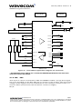
A serial link interface is available complying with V24 protocol signalling but not
with V28 (electrical interface) due to a 2.8 Volts interface. TX, RTS and DTR can be
either 5V or 3V.
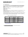
The signals are Tx data (CT103/TX), Rx data (CT104/RX), Request To Send
(CT105/RTS), Clear To Send (CT106/CTS), Data Terminal Ready (CT108-2/DTR)
and Data Set Ready (CT107/DSR).
The set of RS232 signals can be required for GSM DATA services application. The
2 additional signals are Data Carrier Detect (CT109/DCD) and Ring Indicator
(CT125/RI).
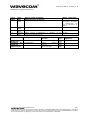
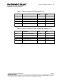
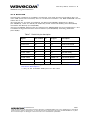
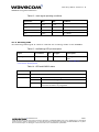
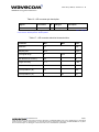
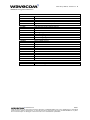
Table 7 : Serial Link pin description
Signal
Pin number I/O
I/O type*
Description
CT103 / TX
25
I
CMOS
Transmit serial data
CT104 / RX
28
O
1X
Receive serial data
CT105 / RTS
30
I
CMOS
Ready To Send
CT106 / CTS
13
O
1X
Clear To Send
CT107 / DSR
27
O
1X
Data Set Ready
CT108-2 / DTR
29
I
CMOS
Data Terminal Ready
CT109 / DCD
5
O
CMOS / 2X
Data Carrier Detect
CT125 / RI
9
O
CMOS / 2X
Ring Indicator
CT102/GND
21,24…**
Ground
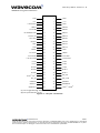
*See Table 3 “operating conditions” in subdivision 4.1.1The 50-pin
connector description
** Any of the available GND pins can be used
25/61
confidential ©
This document is the sole and exclusive property of WAVECOM. Not to be distributed or divulged
without prior written agreement. Ce document est la propriété exlcusive de WAVECOM. Il ne peut
être communiqué ou divulgué à des tiers sans son autorisation préalable.