1
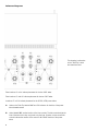
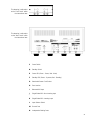
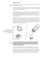
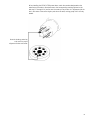
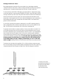
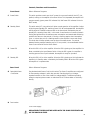
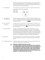
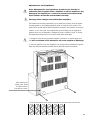
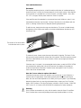
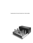
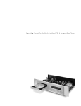
Operating Manual for the Sonic Frontiers Power 3 Amplifiers
Operating Manual for the Sonic Frontiers Power 3 Amplifiers
We at Sonic Frontiers hope you will derive many years of listening pleasure with your
new Power 3 Amplifiers. This Operating Manual contains important information regarding the operation and care of these Amplifiers. Be sure to read this manual carefully and
follow these instructions in order to keep them performing and sounding their best.
Please contact Sonic Frontiers if you have any questions - a Customer Service Representative will be pleased to assist you.
Contents
Unpacking................................................................................................................1
Quick Setup..............................................................................................................2
Reference Diagrams ..................................................................................................3
Installing the Tubes ....................................................................................................5
Biasing of the Power Tubes.........................................................................................7
Controls, Functions and Connections...........................................................................8
Adjustment for Load Impedance...............................................................................10
Care and Maintenance............................................................................................12
Troubleshooting.......................................................................................................13
Warranty................................................................................................................14
Specifications..........................................................................................................15
This symbol is intended to alert the
user to the presence of uninsulated
“dangerous voltage” within the
p ro d u c t ’s enclosure that may be of
sufficient magnitude to constitute
a risk of electric shock to persons.
This symbol is intended to alert the
user to the presence of important
operating and maintenance (servicing)
instructions in the literature accompanying the appliance.
Sonic Frontiers Inc. can be reached at:
2790 Brighton Road, Oakville, Ontario, Canada L6H 5T4
Tel: (905) 829-3838 Fax: (905) 829-3033
E-Mail: [email protected] WWW: http: //www.sonicfrontiers.com
10/96 SKU#56800
Unpacking
At this point we can assume that you have successfully opened the box flaps and found
this manual. These boxes were designed to ensure the safe transport of the amplifiers,
Sonic Frontiers strongly recommends the storage of these boxes in a safe, dry place. In
the event that the amplifiers may have to be shipped in the future, the original boxes are
the best means for the protection and safety of the Power 3s during transportation.
You may want to enlist a friend’s help to remove the amplifiers from the boxes, the
weight can make this awkward (hint: the back of the chassis is the heavy end). Here is a
chart listing what you will find in the box:
Power 3
(per mono channel)
Tube Complement:
8-6550C or KT88
4-6922
2-5687
Slot Screwdriver
1
Phillips Screwdriver
1
Biasing Tool
1
Power Cord
1
Pearl Tube Coolers
(with O rings)
2
Cotton Gloves
1 pair
Extra Fuse
2
Amplifier
1
Tube Cover
1
Warranty Card
1
Operating Manual
1
When unpacking the Power 3 Mono Amplifiers be sure to keep tubes grouped with the
amplifier of the same box.
If after your inspection of the contents there is a discrepancy, contact your dealer or
Sonic Frontiers immediately.
1
Quick Setup
At this point we urge you to read and understand this manual in its entirety. But if you
desire immediate action and have skill and/or past experience with tube hardware, follow these steps.
1. Place the amp on a hard flat surface that will not impede airflow under the amplifier’s
chassis (carpeting or area rugs are NOT acceptable as hard surfaces).
2. Ensure the Power 3s are in Mute mode (this selector switch is on the rear of the
chassis). When disconnecting and connecting cable, placing the amplifier in Mute is an
excellent practice.
3. Tube bias was set at the factory prior to shipment. Tubes are also marked for their corresponding socket location. Carefully inspect each and install appropriately. Check
Installing the Tubes and Biasing of the Power Tubes (a must read) for further
clarification.
4. Connect your preamplifier’s left and right balanced or single-ended outputs to the left
and right inputs of the mono amplifiers.
5. Connect the speakers to the positive (+) red and negative (-) black output binding
post. Note: It is not recommended to operate any tube amplifier without
its speaker load connected.
6. Select the input for use via the selector switch: XLR-Balanced, Single-Ended NonInverting, Single-Ended Inverting .
7. Power up your system turning the power amplifiers on last ensuring that both green
LEDs are on (no Standby or Mute activation). Allow 5 minutes of warm up and then play
some music.
2
Reference Diagrams
This drawing is referred to
as the “Tube Top” within
the instructional text.
Tube locations V1 to V4 indicate placement for the four 6922 tubes.
Tube locations V5 and V6 indicate placement for the two 5687 tubes.
Locations V7 to V14 indicate placement for the 6550C/KT88 power tubes.
A
Holes on the Tube Top labeled “A” are LED indicators for the bias of the power
tubes situated nearest.
B
Holes labeled “B” are the location of the bias controls. The bias controls adjust the
bias of the tube which they are joined to by the lines. Direction arrows around the
controls indicate the rotation of the control to INCREASE the bias of the power
tubes.
3
This drawing is referred to
as the “Front Panel” within
the instructional text.
This drawing is referred to
as the “Rear Panel” within
the instructional text.
C
Power Switch
D
Standby Switch
E
Power LED (Green - Power; Red - Mute)
F
Standby LED (Green - Operate; Red - Standby)
G
Detachable Power Cord Socket
H
Fuse Location
I
Balanced XLR Input
J
Single-Ended RCA Non-Inverting Input
K
Single-Ended RCA Inverting Input
L
Input Selector Switch
M
Ground Post
N
Loudspeaker Binding Posts
4
Installing the Tubes
Be sure the amplifier is OFF (Power Switch Out) before installing any tubes or when any
of the tube sockets are empty.
Wearing the cotton gloves provided with the amplifier when handling tubes will prevent
skin oils from depositing on the glass surface of the tubes. The oils could cause the tubes
to become “gassy” and fail prematurely.
Inspecting the tube boxes that come with the amplifiers (when setting up the Power 3 be
sure to keep tubes with the amplifier they were packed with), you will notice that the
boxes and power tubes themselves are labeled to corresponding sockets also labeled on
the tube surface. See Reference Diagrams for further clarification. Insert each tube in the
corresponding socket.
Starting with the 9 pin small signal tubes (the 6922s and 5687s), pay extra attention to
the tube pins and socket holes for these tubes. You will notice an open space where an
imaginary tenth pin or hole would be. This is for proper tube alignment. Be sure pins are
in line with holes when installing tubes. Gently rock the tube into the socket until the tube
is firmly seated. The 6922 tubes are inserted into sockets designated V1 to V4 and the
5687 tubes are inserted into sockets V5 and V6.
Note the larger space
between two of the pins and
holes for proper alignment of
tube and socket.
DO NOT PLACE 6922 TUBES IN A 5687 SOCKET OR A 5687 TUBE IN
A SOCKET DESIGNATED FOR A 6922 TUBE. THIS COULD RESULT IN
DAMAGE TO THE TUBE, AMPLIFIER (OR BOTH) THAT WOULD NOT BE
COVERED UNDER WARRANTY.
The 5687 tube is designed to run very hot. In its implementation in the Power 3, it is
being used at 1/3 its ratings. Even at this rating, the 5687 still gets hot and therefore,
the 2 Pearl ™ Tube coolers should be installed over the 5687 tubes. The chassis has been
designed with larger holes to accommodate these essential devices to keep these tubes
“comfortable” and allow efficient operation. Just slide the coolers over the already
installed tubes and add the rubber O rings around the coolers to clamp them in place.
5
When installing the 6550C/KT88 power tubes, match the numbers designated on the
metal base of the tube or the tube boxes to the corresponding markings printed on the
tube top (V7 through V14) and be sure the center pin key locator is in alignment with the
slot in the center of the socket. Again push down the tube, rocking gently until it is firmly
seated.
Note the locating center key
and notch for proper
alignment of tube and socket.
6
Biasing of the Power Tubes
Bias voltage applied to the grids of the power tubes in the output stage should be
checked from time to time (once a month) to keep these tubes operating at the optimum
operating point. A properly biased power tube will have a longer, happier life.
To check the bias of the 6550C/KT88 tubes, place the amplifier in mute with the power
on and the amplifier in operate mode (STANDBY LED Green; Power LED Red-for MUTE).
Looking at the tube top, take note of the power tube location and the bias LED below the
surface of the chassis next to each tube. Also note the printed line that leads to each
power tube. At the opposite end of this line is the bias adjustment for each power tube, a
small slotted metal shaft, again located below the chassis surface. See reference diagrams for further clarification.
If a bias LED is glowing red the tube is overbiased; if a bias LED is glowing green the
tube is underbiased, both conditions cause undue wear and/or are not optimal for the
tube. The LED should not be glowing at all for the proper operating bias.
To properly bias the tubes is a simple procedure. For the power tubes on the left (V7 to
V10) insert the biasing driver into the slot head of the bias adjustment control and turn
the driver to adjust the control counterclockwise so the LED is green. Turn the adjustment
back clockwise until the LED begins to dim. At this point; through careful adjustment,
continue slowly turning the bias control, stopping the moment the LED goes out. No light
from the LED indicates a properly biased tube. For the most accurate biasing, the
biasing controls should always be rotated from the LED emitting green
to the LED emitting no light, stopping immediately, as soon as the LED
emits no light. Repeat procedure on the next tube until all tubes are properly biased.
For tubes on the right side of the amplifier (V11 to V14) the biasing controls are opposite. Turn the biasing controls clockwise initially to decrease bias so the LED is green and
counterclockwise until the LED goes out. Refer to the Tube Top diagram for direction.
A cutaway of the tube
top showing the location of
the biasing controls below
the tube top surface
and the biasing driver.
7
Controls, Functions and Connections
Front Panel
Refer to Reference Diagrams.
C
Power Switch
This switch provides control over the AC power from your wall outlet. When OFF (out
position) nothing on the amplifier is functional. When ON (depressed) the amplifier will
operate normally (green power LED indicates ON; Red Power LED indicates ON but in
MUTE mode).
D
Standby Switch
This switch when OFF (out position) will allow normal operation of the amplifier (indicated by the green Standby LED, assuming Power ON). When depressed ON the amplifier
will be placed in STANDBY mode and will not be operational (indicated by the red
standby LED, assuming Power ON). In this mode, a small amount of current will remain
flowing through the tubes, this reduces power consumption and extends tube life during
periodic short term non-use periods (i.e. during a listening session when interruptions
occur, or a short time prior to a listening session so the amplifier is warm and ready).
This mode also will keep optimal warm up times of the tubes shorter. For periods
between listening sessions extending over a 12 hour period, it is recommended that the
Power 3s are turned off via the Power Switch.
E
Power LED
When this LED is off, so is the amplifier. When the LED is glowing red, the amplifier is in
Mute, controlled by the Input Selector Switch. When the LED is green, the amplifier is
receiving power and an input is selected, the amplifier is ready for operation.
F
Standby LED
When this LED is off, so is the amplifier. When the LED is glowing red, this indicates the
amplifier is in Standby mode, controlled by the Standby Switch. When the LED is green
the amplifier is in operate mode.
Rear Panel
Refer to Reference Diagrams.
G Detachable Power
Cord Socket
H
Fuse Location
Plug the detachable Power Cord into this socket. The Power 3 amplifiers are configured
for the operating voltages in which they are sold. See shipping box or Voltage/
Impedance sticker on rear of the chassis for voltage settings. If a different operating
voltage is required, please contact an authorized Sonic Frontiers dealer or the factory
directly.
This socket/holder houses a 7 amp slo-blo fuse for countries with AC supplies
rated between 110-120V or a 3.5 amp slo-blo fuse for countries operating on
a 220-240V supply.
REPLACEMENT FUSES MUST BE RATED WITH THE SAME SPECIFICATIONS
AS THE ORIGINAL FUSE.
8
Damage due to bypassing the fuse or due to replacement of a fuse of higher ratings will
not be covered under the warranty. To access the fuse, insert the slotted screwdriver,
pushing to compress the internal spring and turn counterclockwise to unlock the housing.
The spring will then eject the fuse and the housing.
I
Balanced XLR Input
These inputs accept an XLR balanced connection from the preamp’s balanced outputs.
Note: The XLR pin configurations are as follows:
Pin#1- Ground
Pin#2- Positive
Pin#3- Negative
J
Single Ended RCA
Non-Inverting Input
These inputs accept an input signal from a single-ended output of a preamp or source
that is in ....absolute phase or are used if it is desired to maintain the phase of the signal
from the preamp. Simply explained, this input does not invert the phase of the output signal relative to its input.
K
Single Ended RCA
Inverting Input
These inputs accept an input signal from a single-ended output of a preamp or source
that is 180°out of phase relative to the original signal and correction for this configuration is desired. The input on the Power 3 does invert the phase of the output signal, relative to the input signal.
L
Input Selector Switch
This switch must be rotated to the desired position to select the desired input, XLR
Balanced, RCA Single-Ended Non-Inverting (+) or Inverting (-) for normal operation. In
the MUTE position, this control allows for BIASING CONTROL of the power tubes and
for safe cable swapping without shutting down the amplifier. When in the MUTE position
the front panel Power LED will turn RED. Note: This position is purposely positioned at 12
o’clock so it can be easily determined when access is obscured. The front panel Power
LED will also turn red if this switch has selected an input which has no connection.
M Ground Post
This post is offered for use when a ground connection is required (i.e. when amplifier’s
function is being tested by a technician). It has no use for day-to-day audio related
operation.
N Loudspeaker Binding Posts
These posts are used to connect the amplifiers to the speakers; positive terminal to positive terminal, negative terminal to negative terminal.
WARNING: AMPLIFIER OUTPUT IS BALANCED.
CARE MUST BE TAKEN TO ENSURE THE AMPLIFIER IS NOT CONNECTED
TO LOUDSPEAKERS (CERTAIN SUBWOOFERS) OR LOUDSPEAKER SWITCHBOXES THAT HAVE A COMMON GROUND. CONSULT YOUR DEALER OR
SONIC FRONTIERS DIRECTLY FOR FURTHER CLARIFICATION REGARDING
CONNECTIONS TO ITEMS IN THESE UNIQUE CASES. DAMAGE TO THE
AMPLIFIER OR CONNECTED EQUIPMENT WILL NOT BE COVERED UNDER
WARRANTY IF THESE WARNINGS ARE IGNORED.
9
Adjustment for Load Impedance
Note: Adjustment for load impedance should only be done by an
authorized Sonic Frontiers dealer, distributor or service technician. Any
damage to the amplifier as a result of a person(s) not authorized by
Sonic Frontiers will not be covered under warranty.
Warning: Lethal voltages exist within these amplifiers.
The speaker load handling capabilities of your amplifier was factory set to the impedance designated on the Voltage/Impedance sticker on the back of the chassis. In the
event that you should require different impedance operation, the amplifier can be set to
handle 2, 4 or 8 ohm loads. Some experimenting of this setting may be required for
speakers which vary considerable in impedance across a frequency range. To change
the output setting have your Sonic Frontiers’ dealer follow these steps:
1. Unplug all connections to the power amplifiers, namely the AC power supply cord
and wait a minimum of 20 minutes for all power supplies to discharge.
2. Place the amplifier on the rear handles so it is upright and the underside is exposed.
Using the Phillips screwdriver provided unscrew the bottom panel and remove.
After removing the
bottom cover, locate
the terminal block
in the left rear corner.
3. Look for the terminal block under the transformer housings which looks like this:
10
4.Using the slot screwdriver provided with the amp, deal with one connection at a time,
loosening off the tap screws of the first spade lug connection and tightening to the
desired tap. The final connections should resemble these renderings:
8 Ohm Impedance Connections
FRONT OF
THE AMPLIFIER
4 Ohm Impedance Connections
FRONT OF
THE AMPLIFIER
2 Ohm Impedance Connection
FRONT OF
THE AMPLIFIER
5. Repeat for each channel.
6. Ensure all 12 screws per terminal block are tightened so there is no chance of them
vibrating loose.
7. Replace the bottom cover and all external connections.
11
Care and Maintenance
Placement
The amplifiers must be placed on a hard flat surface with plenty of unobstructed space
around the Power 3 to allow for free movement of air for proper cooling. If the amplifier
is to be placed on a carpeted floor, a Wood, Ceramic, Concrete, Marble... tile or slab
18” x 22” (or larger) must be place under each Power 3 Amplifier.
If the amplifiers are left unattended or are exposed near small children or pets, it is recommended that the tube cover be used. Cooling of the tubes is not as effective with the
cover on, although it does allow for adequate operating temperatures.
To add the cover, simply place the cage over the tube top. The cover is locked through
the tightening of the large screw heads on the sides located between the tube top and
transformer case.
The location of the screw which
locks the tube cover in place.
To remove the cover, loosen screws that were indicated for fastening. The Power 3’s fastening screw is spring loaded for release after it is loosened. Then while applying a small
amount of outward tension at the screw locations, lift the cover straight up and away
from the tubes.
If the tube cover is not used, it is recommended that the tubes, namely the 6550C/KT88s
are protected from settling dust in NON-USE periods. Dust settling on the tubes can
cause heat impairment of the tubes. Therefore, when the amplifier is NOT IN USE, a
cloth or dust cover should be used.
How do I know when to replace the tubes?
If the tubes lack power to drive your speakers, are hard to bias or won’t hold bias, it
could be time for replacements. Power tubes generally wear faster then small signal
tubes, but how much faster depends on how often you run your system. If you need help
determining these factors or sourcing replacement tubes, contact your Sonic Frontiers
dealer, Sonic Frontiers or The Parts Connection (a division of Sonic Frontiers, 1-800-7690747 in the U.S. or Canada, (905) 829-5858 for elsewhere) for further assistance.
Cleaning
Sonic Frontiers recommends only a dry cloth be used to clean the Power 3 Amplifiers.
Sonic Frontiers does not warranty damage done through liquids spilled on circuitry.
12
Troubleshooting
If at any time the amplifiers should fail to work, follow these steps:
1. Check that all tubes are fully seated in their proper sockets.
2. Check all connections at the rear panel.
3. Check that the amplifier is not in MUTE mode.
4. Check that the proper input is selected via the Selector Switch.
5. Check that the amplifiers are in POWER ON mode and NOT in STANDBY mode.
6. Check other equipment and connections to that equipment in your system, from speakers to source.
7. Check that no fuses are blown in all equipment and/or breaker switches in the home.
If this checklist fails to be fruitful, contact your dealer or Sonic Frontiers directly.
Servicing
If the amplifier ever requires servicing in or outside of the warranty limitations, contact
your Sonic Frontiers dealer or Sonic Frontiers directly.
Break-in Time
As with all audio electronic products, the ultimate sonic character of the Power 3 will not
be realized until and unless the unit receives a minimum of approximately 70 hours of
signal break-in time (i.e. the Power 3 is on and outputting a signal).
Safety Instructions
1. Water and Moisture - This product should not be used near water. To prevent fire or
shock hazard, do not expose this product to rain or moisture.
2. Heat - This product should be situated away from heat sources such as radiators, heat
registers, stoves, or other appliances which produce heat.
3. Power Sources - This product should be connected to an AC power source of the
proper rated voltage. The original shipping container will stipulate the AC voltage this
unit can operate with correctly.
4. Servicing - Do not open this product for any reason. No user serviceable parts inside.
Refer servicing to an authorized service technician.
5. Non-Use Periods - The power cord of this product should be unplugged from the outlet when left unused for an extended period of time.
6. Do not remove the top or bottom covers while the unit is “on”, or connected to an AC
power source. Cover screws could fall through the ventilation slots and cause electrical
damage to the amplifier.
13
Warranty
Disclaimer of Liability
Under no circumstances does Sonic Frontiers, Inc. assume liability or responsibility for
injury or damages sustained in the use or operation of this equipment or for damages to
any other equipment connected to it. Sonic Frontiers, Inc. reserves the right to make
design changes or improvements without the obligation to revise prior versions. All specifications are subject to change without notice.
Limited Five Year Warranty
Sonic Frontiers, Inc. warrants to the purchaser that each amplifier is free of manufacturing defects for a period of five (5) years from the date of purchase. This five (5) year limited non-transferable warranty excludes all vacuum tubes, which we warrant for a period
of twelve (12) months. To receive this warranty, the original purchaser must complete and
mail to Sonic Frontiers, within thirty (30) days from the date of purchase, the enclosed
Warranty Registration Card. Sonic Frontiers, Inc. will then validate the warranty to the
original purchaser. This warranty is subject to the following conditions and limitations:
1. Warranty applies only to the original purchaser.
2. This warranty is void and inapplicable if the product has been handled other than in
accordance with the instructions in this Owner’s Manual, abused or misused, damaged
by accident or neglect or in being transported, or the defect is due to the product being
tampered with, modified or repaired by anyone other than Sonic Frontiers, Inc. or
an authorized Sonic Frontiers repair depot.
3. Warranty does not cover normal maintenance.
4. Sonic Frontiers, Inc. shall not be responsible in any way for consequential or indirect
damages or liabilities resulting from the use and operation of the product covered herein
or resulting from any breach of this warranty or any implied warranty relating to said
product.
During this period, Sonic Frontiers, Inc. will repair or replace any defective components
free of charge. A Return Authorization Number (RA Number) is required before
any product is returned to our factory for any reason. This number must be visible on the
exterior of the shipping containers for Sonic Frontiers to accept the return.
Units shipped to us without a Return Authorization Number or without a visible RA
Number on the exterior of the shipping containers will be returned to the sender, freight
collect.
Units to be repaired by Sonic Frontiers, Inc. must be sent shipping and insurance prepaid by the original purchaser in the original packing material. A returned product
should be accompanied by a written description of the defect. Repaired units will be
returned by Sonic Frontiers, Inc. shipping and insurance prepaid.
All other warranties or conditions either written or implied are void.
Note: In foreign markets (anywhere outside of Canada and the USA), the warranty is supplied by the authorized International Distributor. Exact terms and conditions may vary.
14
Specifications
Note: Power ratings based on a 117 VAC power line input. All specifications are made
on the 8 ohm taps, utilizing an 8 ohm load unless otherwise specified.
Power Output:
SMPTE Intermodulation
Distortion:
220 watts continuous at 8, 4 and 2 ohms from 20 Hz to 20 kHz with less than 1% total
harmonic distortion terminated with rated load (typically <0.5% @ 220 watts 1 kHz)
Actual power output available at clipping (defined as <1% THD) approximately 240
watts RMS
<1% 20 Hz to 20 kHz @ 220 watts output
Power Bandwidth:
15 Hz to 60 kHz (-0.5 dB points)
5 Hz to 120 kHz (-3 dB points)
Frequency Response:
5 Hz to 75 kHz @ 1 watt (-0.5 dB points)
2 Hz to 150 kHz @ 1 watt (-3 dB points)
Input Sensitivity
(for 220 watt output):
2.2V RMS balanced for 220 watts output
2.2V RMS single-ended (inverting or non-inverting)
Input Impedance:
200K ohms balanced
100K ohms single-ended (inverting or non-inverting)
Damping Factor:
>50 (determined using the IHF method from RS-490)
Output Impedance:
0.25 ohms at 1 kHz
Negative Voltage Feedback:
18 dB
Hum and Noise:
approximately 400 microvolts of wideband, unweighted noise @ the 8 ohm taps,
input muted; -110 dB below a 220 watt output
Rise Time:
2.8 microseconds
Slew Rate:
19 volts/microsecond
Power Requirements:
110-120 VAC 60 Hz (220-240 VAC); 580VA at rated output, 650VA maximum
and 375VA with no signal input
Tube Complement
(per mono amp):
8 (4 matched pair) x 6550C or KT88 - power output; 4 x 6922 - input/driver; 2 x 5687
high voltage driver
Dimensions (per mono amp):
18” (46 cm) W x 22” (56 cm) D x 9” (23 cm ) H
Weight (approx.):
100 lbs (45 kg) net each (unpacked)
Warranty:
5 year parts & labor; 1 year on the tubes
Sonic Frontiers continually strives to improve their products; specifications are
subject to change without notice.
15