1
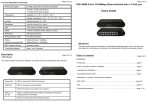
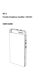
PM-16 Personal Monitoring System User Guide www.elitecoreaudio.com [email protected] 920 South D Street Fort Smith, AR 72901 855-276-2673 i Elite Core PM-16 User Guide Important Safety Instructions WARNING: To ensure a long healthy life for you and your new PM-16 System, please read these instructions before proceeding. Water and moisture Do not expose the equipment to rain or moisture or use in damp or wet conditions. Do not place containers of liquids on surfaces where liquid may spill into any openings. Ventilation Please make certain that the units have proper ventilation. Heat and Vibration Do not locate the equipment in a place subject to excessive heat or direct sunlight. Locate the equipment away from any source which produces excessive heat or vibration. Installation Install and connect the equipment in accordance with the instructions printed in this User Guide. Prevent Damage To prevent damage to the controls and cosmetics avoid placing heavy objects on the control surface, scratching the surface with sharp objects, or rough handling and vibration. Environment Protect from excessive dirt, dust, heat and vibration when operating and storing. Avoid tobacco ash, smoke, drinks spillage, and exposure to rain and moisture. If the equipment or its power supply becomes wet, switch off the power immediately. Allow to dry out thoroughly before using again. Cleaning Avoid the use of chemicals, abrasives or solvents. The control surface is best cleaned with a soft brush and dry lint-free cloth. The faders, switches and potentiometers are lubricated for life. The use of electrical lubricants on these parts is not recommended. The fader and potentiometer knobs may be removed for cleaning with a warm soapy solution. Rinse and allow it to dry fully before refitting them. Protect Your Hearing! To avoid damage to your hearing, do not operate your Elite Core Personal Monitor System at excessively high volume. Continued exposure to high volume sound can cause frequency selective or wide range hearing loss. Consult the User Guide for recommended settings. ii Elite Core PM-16 User Guide Limited One Year Warranty This product was manufactured in the USA by Elite Core Audio and is warranted to be free from defects in materials or workmanship for a period of one year from the date of purchase by the original owner. To ensure a high level of performance and reliability for which this equipment has been designed and manufactured, please read this User Guide before operating. If a component fails, notify and return the defective unit to Elite Core Audio or its authorized representative as soon as possible. Repairs are covered under warranty subject to the following conditions: 1. The equipment has been installed and operated in accordance with the instructions in this User Guide. 2. The equipment has not been subject to misuse (intended or accidental), neglect, or alteration. 3. Any previous service or repair has been carried out by Elite Core Audio or its authorized agent. 4. The defective unit is to be returned (shipping prepaid) to Elite Core Audio with proof of purchase. Please contact Elite Core Audio to request an RMA number. 5. Pack the unit(s) being returned carefully to avoid shipping damage. FCC Class A Radio Frequency Interference Statement This product has been tested and found to comply with the limits for a Class A digital device pursuant to Part 15 of the FCC Rules. These limits are designed to provide reasonable protection against harmful interference when the equipment is operated in a commercial environment. This product generates, uses, and can radiate radio frequency energy and, if not installed and used in accordance with the manufacturer’s instruction manual, may cause harmful interference with radio communications. Operation of this product in a residential area is likely to cause harmful interference, in which case you will be required to correct the interference at your own expense. This device complies with Part 15 of the FCC Rules. Operation is subject to the following two conditions: 1. This device may not cause harmful interference. 2. This device must accept any interference received, including interference that may cause undesired operation. These limits are designed to provide reasonable protection against harmful interference in a non-residential installation. However, there is no guarantee that interference will not occur in a particular installation. If this equipment does cause harmful interference with radio or television reception, which can be determined by turning the equipment off and on, you are encouraged to try to correct the interference by one or more of the following measures: 1. Reorient or relocate the antenna of the radio/television receiver. 2. Increase the separation between this equipment and the radio/television receiver. 3. Plug the equipment into a different outlet so that the equipment and the radio/television receiver are on different power mains branch circuits. 4. Consult a representative of Elite Core Audio or an experienced radio/television technician for additional suggestions. iii Table of Contents Important Safety Instructions ............................................................................................. ii Limited One Year Warranty ................................................................................................ iii FCC Class A Radio Frequency Interference Statement ............................................... iii PM-16 System Overview ...........................................................................................................7 IM-16 Input Module .....................................................................................................................9 IN Connectors ...........................................................................................................................9 THRU Connectors ....................................................................................................................9 TRS Send/Return ..................................................................................................................9 Multichannel Record Output...............................................................................................9 System Expansion ................................................................................................................9 NETWORK Connector ..........................................................................................................10 SIG and CLIP LEDs.................................................................................................................10 POWER Inlet ............................................................................................................................10 DM-8 Distribution Module ......................................................................................................11 PM-16 Personal Mixer ..............................................................................................................13 Channel Controls ...................................................................................................................13 LEVEL .................................................................................................................................13 PAN ....................................................................................................................................13 SIG ......................................................................................................................................13 Master Controls ......................................................................................................................14 MASTER Level ....................................................................................................................14 COMPRESSION Level.........................................................................................................14 Graphic EQ Sliders .............................................................................................................14 AMBIENCE Level................................................................................................................14 LEDs ...................................................................................................................................14 Rear Panel .................................................................................................................................15 v Elite Core PM-16 User Guide PM-16 System Connections ..................................................................................................17 Standard PM-16 Personal Monitoring System with One DM-8 ..............................17 System with One DM-8 and More than Eight PM-16s ...............................................17 PM-16 System Without a DM-8 .........................................................................................18 System with Additional DM-8s ..........................................................................................18 Using LINE OUT .....................................................................................................................18 PM-16 System Specifications ..............................................................................................19 vi Elite Core PM-16 User Guide PM-16 System Overview Welcome to the Elite Core PM-16 Personal Monitoring System. You have just obtained one of the best sounding and elaborately featured monitoring systems available at any price. We know you'll be happy with the PM-16 system. If you have any comments or questions, please get in touch with us. We like to get feedback from and interact with our users: • Web www.elitecoreaudio.com • Email [email protected] • Telephone 855-276-2673 The PM-16 Personal Monitoring System consists of three components: • IM-16 Input Module • DM-8 Distribution Module • PM-16 Personal Mixer IM-16 Input Module The IM-16 Input Module is a 16-channel A/D interface between a console (via channel inserts, direct outputs, aux sends), and the DM-8 Distribution Module or PM-16 Personal Mixer. Figure 1 IM-16 Input Module DM-8 Distribution Module The DM-8 Distribution Module routes 16 digital audio channels from the IM-16 to the PM-16 Personal Mixers. One DM-8 can power eight PM-16s. Figure 2 DM-8 Distribution Module 7 Elite Core PM-16 User Guide PM-16 Personal Mixer The PM-16 Personal Mixer has: • 16 channels, each with a LEVEL and PAN knob. • MASTER level, COMPRESSION, and three-band graphic EQ. • AMBIENCE level that blends in sound captured by the built-in mic. Figure 3 PM-16 Personal Mixer We recommend using a DM-8 Distribution Module to deliver AC power and audio to the PM-16s but it is not required. See PM-16 System Connections on page 17 to learn how to connect the PM-16 with or without a DM-8. 8 Elite Core PM-16 User Guide IM-16 Input Module The IM-16 Input Module is a 16-channel A/D interface between the mixing console and the DM-8 Distribution Module or PM-16 Personal Mixer. Figure 4 IM-16 Input Module IN Connectors Route the console’s channel inserts, direct outputs, and/or aux sends to the ¼-in IN 1–16 connectors. THRU Connectors The THRU 1–16 connectors are provided to route the individual analog audio channels elsewhere. TRS Send/Return Some console’s have a TRS send/return jack that requires a return signal to function properly. This can be easily solved using a Y-cable wired so one side is ¼-in TRS, male. The other side splits into two ¼-in TS plugs, both male, wired as follows: • TS#1 carries the console’s T and ground. • TS#2 carries the console’s R and ground. Typical mixers connect T to IN and R to THRU but check your console’s wiring diagram to confirm. Multichannel Record Output Route the 16 analog inputs to a recorder or interface. This can be very useful in solving routing issues in systems with limited patching. System Expansion Route the analog inputs to another IM-16 or even another manufacturer’s input module. Many installations have an existing monitoring system, but have chosen the PM-16 to expand their infrastructure. The THRU connectors make this cross-product integration possible. See System with Additional DM-8s on page 18 for other ways to expand a PM-16 system. 9 Elite Core PM-16 User Guide NETWORK Connector Connect a standard CAT5E cable from the IM-16’s RJ-45 NETWORK connector to the PoE x1 input on the DM-8 or NETWORK IN on the PM-16. See PM-16 System Connections to learn how to interconnect all PM-16 System components. SIG and CLIP LEDs Each channel has two front panel LEDs: • SIG lights green to indicate a signal within normal operating range. • CLIP lights red to indicate the signal is within 3 dB of clipping. Adjust the console’s outputs to the IM-16 so each channel’s SIG LED lights green. POWER Inlet To power up the IM-16, connect the 18 VAC 8.3 mA power supply (provided) to the POWER inlet. There is no on/off switch. 10 Elite Core PM-16 User Guide DM-8 Distribution Module One DM-8 Distribution Module can deliver power and audio to eight PM-16 Personal Mixers. Since the DM-8 delivers power over the CAT5E cable, its PM-16s do not need a power supply. Figure 5 DM-8 Distribution Module front panel (top), and rear panel (below) The front panel has the following LEDs and connectors: • Power: The LED on the far left lights red when the power supply is connected to the DM-8 and an AC power source. • PoE: These eight LEDs (one per Ethernet connection) light yellow to indicate that the PM-16 connected to that output is receiving power from the DM-8. • LINK/ACT: These eight LEDs (one per Ethernet port) light green to indicate audio activity. • G9: The left Ethernet connector receives input from IM-16; the right connector is not an Ethernet connector and is reserved for future use. • PoE1x–PoE8x: Outputs for up to eight PM-16 Personal Mixers The rear panel of the DM-8 has the following: • Power: This switch powers the DM-8 on and off. • 48 VDC IN: Connect the 48 VDC 2.5 mA power supply to this inlet and an AC power source. Make sure the Power switch is off before connecting the power supply! See PM-16 System Connections to learn how to interconnect your system. 11 Elite Core PM-16 User Guide 12 Elite Core PM-16 User Guide PM-16 Personal Mixer The PM-16 Personal Mixer has: • 16 channels, each with a LEVEL and PAN knob. • MASTER level, COMPRESSION, and three-band graphic EQ. • AMBIENCE level blends in ambient sounds from the built-in mic. Figure 6 PM-16 Personal Mixer Channel Controls LEVEL The LEVEL knob controls the channel volume. Use this in conjunction with the MASTER knob to set the mix and overall listening level. The gain varies over a wide range to accommodate soft and loud instruments. We recommend keeping the channel LEVEL controls lower than the MASTER level. See the SIG section below to avoid clipping the channel input. PAN PAN sets the channel’s left/right balance. This allows each PM-16 Personal Mixer to set not only its own mix but unique stereo assignments as well. SIG The SIG LED lights green to indicate a normal input signal level and red when 3 dB from clipping. 13 Elite Core PM-16 User Guide Master Controls MASTER Level The MASTER knob sets the overall level sent to the headphone output and LINE OUT connectors. If both headphones and the monitors are connected, set the appropriate headphone level first then adjust the monitor amp to be compatible. NOTE: Always check the listening level before putting on headphones. We recommend keeping the channel LEVEL controls lower than the MASTER. COMPRESSION Level Turning the COMPRESSION knob clockwise increases the compression ratio. The output automatically compensates for gain reduction. The signal is not compressed when the knob is turned fully counterclockwise. Graphic EQ Sliders Lo, Mid, and Hi frequency bands can be boosted or cut 12 dB. Center the sliders to the detented position for a flat response. AMBIENCE Level The AMBIENCE knob sets the PM-16’s built-in mic level. The AMBIENCE mic can reduce the isolated feeling some musicians experience when using IEMs because they can hear: • the “room sound;” • conversation not spoken into a mic; • instruments playing in the room but not present in the mix. LEDs The two columns of LEDs to the left of the MASTER level knob indicate the post-EQ stereo output level. If either red clip LED lights, we recommend reducing your output level to preserve headroom. The clip LED lights 3 dB below actual clipping. The red LED to the right of the output LEDs lights when the PM-16 is connected to a power source, either from the DM-8 or its own power supply. 14 Elite Core PM-16 User Guide Rear Panel The rear panel has the following connections: • LEFT and RIGHT ¼-in LINE OUT • RJ-45 NETWORK IN and OUT • Stereo ¼-in Output Compatible with headphones, earbuds, custom IEMs, or our optional EC-WBP wired body pack • DC POWER inlet Figure 7 PM-16 Rear Panel See PM-16 System Connections to learn how to interconnect the PM-16 components. 15 Elite Core PM-16 User Guide 16 Elite Core PM-16 User Guide PM-16 System Connections The PM-16 Personal Monitoring devices use standard CAT5E cables, and work with the Neutrik™ Ethercon connector for added protection and stability. We recommend a maximum cable length of 500 ft (150 m). All PM-16 systems must use an IM-16 Input Module and one or more PM-16 Personal Mixers. We recommend using the DM-8 Distribution Module to deliver audio and power to the PM-16s, but it is not required (see below). The DM-8 can power up to eight PM-16s using the Power-Over-Ethernet (PoE) convention. Each system described below first requires interfacing the console’s channel inserts, direct outputs, and/or aux sends to the IM-16 Input Module’s IN connectors. Standard PM-16 Personal Monitoring System with One DM-8 To interconnect a standard PM-16 System: 1. Connect a CAT5E cable between the IM-16’s NETWORK and the DM-8’s left G9 connectors. 2. Connect a CAT5E cable between the DM-8’s PoE 1x Ethernet and the first PM-16’s NETWORK IN connectors. 3. Increment the DM-8’s output (i.e., PoE 2x, PoE 3x, etc.), and repeat step 2 until all PM-16s are connected. See below if more than eight PM-16s are required. System with One DM-8 and More than Eight PM-16s If your system requires more than eight PM-16s and you do not have a second DM-8: 1. Follow the directions above to connect a standard PM-16 Personal Monitoring System with eight PM-16 Mixers. 2. Connect a CAT5E cable between a NETWORK OUT on any PM-16 Mixer connected to the DM-8, and PM-16 Mixer #9’s NETWORK IN connectors. 3. Repeat step 2 for additional PM-16 Mixers. 4. Connect a power supply for each additional PM-16 Mixer that is not connected to the DM-8. 17 Elite Core PM-16 User Guide PM-16 System Without a DM-8 A PM-16 can receive audio directly from the IM-16 Input Module and pass it to other PM-16s. However, each PM-16 must use its own power supply. To connect PM-16s without a DM-8: 1. Connect a CAT5E cable between the IM-16 Input Module’s NETWORK and the PM-16 #1’s NETWORK IN connectors. 2. Connect a CAT5E cable between PM-16 #1’s NETWORK OUT to the PM-16 #2’s NETWORK IN. 3. Repeat step 2 until all PM-16s are daisy-chained together. There is no limit on the number of PM-16s if all use their own power supply. System with Additional DM-8s If more than eight PM-16s are required, DM-8s can be daisy-chained together: 1. Follow the directions above to connect a standard PM-16 Personal Monitoring System with one DM-8, but connect only seven PM-16 Mixers from DM-8 #1. 2. Connect a CAT5E cable between DM-8 #1’s PoE 8x output and DM-8 #2’s left G9 input. 3. Connect additional PM-16s to DM-8 #2. 4. If more than 15 PM-16s are required, repeat step 2 to connect DM-8 #2’s PoE 8x output to DM8 #3’s left G9 input. There is no limit to the number of DM-8s that can be daisy-chained together. Each PM-16 connected to a DM-8 does not require its own power supply. Using LINE OUT The ¼-in TRS LINE OUT connectors can route the PM-16’s stereo output to powered speakers/monitors, wireless IEM systems, amps or other line level devices. If the headphone output and LINE OUT are used simultaneously, set the headphone level first, then attenuate the powered speakers and/or amps. 18 Elite Core PM-16 User Guide PM-16 System Specifications Output impedance balanced Output Noise Level -76 dB Headphone Output Impedance 25 Line Out Impedance 50 Frequency Response 25 Hz to 20 kHz, ±3 dB Crosstalk -70 dB (400 Hz to 16 kHz) Distortion 0.08% Signal to Noise Ratio 66 dB (22 Hz - 22 kHz) Latency < 0.878 ms (measured from analog input to analog output) Grounding Headphone: sleeve of TRS jack is grounded to the PM-16 chassis Line Out: sleeve of line out jacks are grounded to the PM-16 chassis Chassis: Chassis ground connected to local power input Dimensions and Weight PM-16: IM-16: DM-8: H = 3.5”; D = 6.25”; H = 1.75”; D = 6.25”; H = 1.75”; D = 3.75”; W = 11.5”; W = 19.0”; W = 6.0” Weight = 4.15 lb Weight = 5.90 lb Weight = 1.05 lb PM-16 Headphone Output Level Z () 600 480 360 300 180 120 32 16 8 4 Vrms (V) 2.12 2.11 2.11 2.10 2.09 2.09 1.96 1.96 1.79 0.98 Vpp (V) 6.00 5.97 5.97 5.94 5.91 5.83 5.55 5.55 5.05 2.77 Irms (mA) 3.5 4.3 5.8 6.9 11.4 16.9 59.8 116 225 246 Ipp (mA) 9.8 12.3 16.3 19.5 32.2 47.8 169.3 328.1 636.4 695.8 7 9 12 14 24 35 117 228 402 241 21 26 34 41 67 98 0.332 0.644 1.1 0.7 Prms (mW) Ppp (mW) 19