1
Installation Instructions
for the MX934i
Multiplex PIR Intrusion Detector
1.0
• Current Draw:
2-Wire:
LED Off:
In Alarm; LED On:
4-Wire:
LED Off:
In Alarm; LED On:
• Standby Power:
• Coverage:
Broad (standard):
Barrier (optional):
Long Range (optional):
• Sensitivity:
• Tamper:
• Temperature:
• Control Panel:
Requirements:
• Options:
Mounting
Connects directly to the Multiplex Bus
of the Control Panel and optionally to
an auxillary 12 VDC source.
Avoid
Moisture
Moving objects
<350 μA draw on Mux Bus.
2 mA draw on Mux Bus.
<350 μA draw on Mux Bus.
0 mA draw on Aux. power.
<350 μA draw on Mux Bus.
3 mA draw on Aux. power.
There is no internal standby battery.
Connect to DC power sources capable
of supplying standby power if primary
power fails. For each hour of standby
time needed, 350 μAh are required.
For UL Listed Requirements, four
hours (1400 μAh) minimum are
required.
35 ft. by 35 ft. (10.7 m by 10.7 m)
35 ft. by 10 ft. (10.7 m by 3.1 m)
70 ft. by 10 ft. (21.4 m by 3.1 m)
Selectable for Standard, Intermediate,
or High.
A tamper condition is signaled through
the Multiplex Bus and displays at the
keypads.
The
storage
and
operating
temperature range is -20°F to +120°F
(-29°C to +49°C). For UL Listed
Requirements, the temperature range
is +32°F to +120°F (0°C to +49°C).
DS7400, DS7400X, or DS7400Xi
control panel with a DS7430 or
DS7436 multiplex expansion module.
The DS7400 and DS7400X require
ROM version 1.07 or greater. 9000
Series Control/Communicators with
D8125MUX Module installed.
B335 Low Profile Swivel Mount
Bracket, B338 Ceiling Mount Bracket,
OMB93-3* Barrier Mirror, OMLR93-3*
Long Range Mirror.
*Shipped in packages of three.
Misalignment of the detector when using an optional
mounting bracket may reduce range and increase dead
zones.
• Reading Bosch Security Systems, Inc. Product Date Codes
For Product Date Code information, refer to the Bosch Security
Systems, Inc. Web site at: http://www.boschsecurity.com/
datecodes/
NOTE:
Control Panel Programming
Refer to the multiplex programming section of your Control Panel
Reference Guide for information on programming multiplex zones
for this device.
3.0
Specifications
• Input Power:
2.0
Mounting Outdoors
Direct or
reflected
sunlight
Hot or cold air
directed onto
sensor
Pets or animals
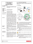
Address Switches
O 1
N
2
3
4
5
6
7
T-Strip
1
2
8
- + B- B+
Tamper Switch
Program
Plugs
Thinwall
Knockout
for
Wiring
Circuit Board Retainer Tabs
2
2
3
LED
Mirror Tracks
H
I
ON
S
OFF
2
1
Location of major items - Circuit Board
1 = Corner 2 = Surface 3 = Bracket
Rear enclosure and mounting holes
The mounting surface should be solid and vibration free.
IMPORTANT
• Select a location that is most likely to intercept an intruder moving
across the coverage pattern. The recommended mounting height
range is 6.5 ft. to 8.5 ft. (2 m to 2.6 m).
• Remove the cover. Insert a thin flathead screwdriver into the
notch at the bottom of the cover and pry up.
• Remove the circuit board/mirror unit from the enclosure. Push
the board/mirror unit toward the top of the enclosure until it clears
its four retainer tabs, then lift it out.
• Open the knock-out wire entrance and route the wiring through.
3.1
Surface or Corner Mounting
• Open two holes for surface or corner mounting.
• Mark the location for the mounting screws. Use the enclosure
as a template. Pre-start the mounting screws.
• Securely attach the detector.
• Replace the circuit board/mirror unit.
• Select the Vertical Angle.
Mirror Information: The mirror is adjustable from +1° to -18° vertically
by sliding the mirror forward or back and ±10° horizontally by
rocking the mirror side to side. To change the mirror, just pull it out
from its resting grooves.
NOTE: Excessive handling of the mirror surfaces may lead to
performance degradation.
- The following chart will help you set the correct Vertical
Angle based on the mounting height, mirror type, and
desired range.
Mounting
Height
Broad
20 (6) 35 (10)
5.2
Sensitivity Mode
Barrier
Long Range
20 (6) 35 (10) 40 (12) 70 (20)
6.5 (2.0)
-10°
-6°
-6°
-4°
-5°
-3°
7.5 (2.3)
-12°
-8°
-8°
-6°
-7°
-5°
8.5 (2.6)
-14°
-10°
-12°
-8°
-9°
-5°
HIGH
INTERMEDIATE
H
Height and desired Range listed in feet (meters)
- The angle adjust markings are on the mirror. Slide the mirror
forward or back until the angle hash marks are in-line with
the markers on each side of the frame.
+2
0
-8
-16
Mirror
4.0
Wiring
POWER
• Connect wiring as shown.
O 1
N
2
3
4
5
6
7
- + B- B+
IN IN IN IN
Configuring Detector
5.1
LED Operation Jumper
STANDARD
Address Switch Settings
BUS
IMPORTANT
NOTE: Do not coil excess wiring inside unit.
• Seal the Wire Entrance using the foam plug provided.
Terminal Descriptions
• 1 (-) and 2 (+): Connect to the AUX Power of the control panel.
This connection is only required if LED operation (other than
during the walk test) is required. Use no smaller than #22 AWG
(0.8 mm) wire between the detector and the control panel.
• 3 (B-) and 4 (B+): Connect to the Multiplex Bus of the control
panel. Use no smaller than #22 AWG (0.8 mm) wire between
the detector and the control panel.
5.0
OFF
• Set the address switch settings (see page 3) before connecting
the MX934i to the multiplex bus.
8
- + B- B+
1 2 3 4
ON
• Standard Sensitivity: Recommended setting for maximum false
alarm immunity. Tolerates environment extremes on this setting.
Not recommended for Long Range or Barrier type patterns. The
detector is shipped in Standard Sensitivity mode.
• Intermediate Sensitivity: Recommended setting for any location
where an intruder is expected to cover only a small portion of the
protected area. Tolerates normal environments on this setting.
This setting will improve your intruder catch performance.
• High Sensitivity: Fast response to intruder signals. For use in
quiet environments where thermal and illumination transients
are not anticipated.
6.0
Only apply power after all connections have been made
and inspected.
AUX
MUX
I
S
No two devices may be set to the same address. Having
two or more units set to the same address may prevent
fault detection or cause multiplex bus failure.
O 1
N
2
3
4
5
6
7
8
- + B- B+
O 1
N
2
3
4
5
6
7
8
• You can find the Address Switch Settings using the chart on
page 3, or by calculating the decimal number of the address.
LED ON
LED OFF
H
I
S
O
N
1
2
3
4
128 64 32 16
5
6
7
8
8
4
2
1
ON
Binary Switch Values (Point 17 shown)
OFF
Zone (Point) Addresses 001 through 008 are reserved for
"on board" points on the DS7400(Xi) Series control panels.
• ON:
• OFF:
Allows the LED to operate when activated by alarm.
The LED will not operate on alarm.
If the detector is powered by the MUX Bus only, the LED
is for Walk Test purposes only. Disable the LED when
Walk Testing is complete. To disable the LED, place the
jumper in the OFF position. If the detector has AUX
Power supplied, the LED operation may be left ON during
normal use.
Page 2
IMPORTANT
Do not set any multiplex devices for Addresses 001-008 when
using a DS7400(Xi) Series control panel.
© 2011 Bosch Security Systems, Inc.
MX934i Installation Instructions
ZONE
(POINT)
ADDRESS
= SWITCH ON
(CLOSED)
SWITCH NUMBER
ZONE
(POINT)
ADDRESS
1 2 3 4 5 6 7 8
001
002
003
004
005
006
007
008
009
010
011
012
013
014
015
016
017
018
019
020
021
022
023
024
025
026
027
028
029
030
031
032
033
034
035
036
037
038
039
040
041
042
043
044
045
046
047
048
049
050
051
052
053
054
055
056
057
058
059
060
061
062
063
064
MX934i Installation Instructions
= SWITCH ON
(CLOSED)
SWITCH NUMBER
ZONE
(POINT)
ADDRESS
1 2 3 4 5 6 7 8
065
066
067
068
069
070
071
072
073
074
075
076
077
078
079
080
081
082
083
084
085
086
087
088
089
090
091
092
093
094
095
096
097
098
099
100
101
102
103
104
105
106
107
108
109
110
111
112
113
114
115
116
117
118
119
120
121
122
123
124
125
126
127
128
= SWITCH ON
(CLOSED)
SWITCH NUMBER
ZONE
(POINT)
ADDRESS
1 2 3 4 5 6 7 8
129
130
131
132
133
134
135
136
137
138
139
140
141
142
143
144
145
146
147
148
149
150
151
152
153
154
155
156
157
158
159
160
161
162
163
164
165
166
167
168
169
170
171
172
173
174
175
176
177
178
179
180
181
182
183
184
185
186
187
188
189
190
191
192
© 2011 Bosch Security Systems, Inc.
= SWITCH ON
(CLOSED)
SWITCH NUMBER
1 2 3 4 5 6 7 8
193
194
195
196
197
198
199
200
201
202
203
204
205
206
207
208
209
210
211
212
213
214
215
216
217
218
219
220
221
222
223
224
225
226
227
228
229
230
231
232
233
234
235
236
237
238
239
240
241
242
243
244
245
246
247
248
249
250
251
252
253
254
255
Page 3
7.0
Setup and Walk Testing
8.0
Before walk testing, the system should be fully wired,
powered, and programmed.
IMPORTANT
• Configure LED Operation Jumper to LED ON.
• Replace the front cover.
9.0
•
•
•
Coverage Patterns
• Refer to the mirror module and pattern drawings for masking
information.
• Before masking, be sure the chosen mirror surface is the correct
one. When removing masking, remember, many adhesives will
either destroy the mirror’s surface or leave residue behind to
reduce coverage performance.
• This product is factory assembled with the look down zones (O,
P, and Q) masked out. If you wish to use these zones, simply
remove the masking tape from the lens.
To Remove Mask,
All testing must be performed with the
front cover in place.
Wait at least two minutes (with no motion in the
coverage area) for the detector to setup.
Walk test across the coverage pattern.
The edge of the coverage is determined by
activation of the LED.
Walk test the unit from both directions to determine the
boundaries.
NOTE:
•
Maintenance
Consult your Control Panel’s User's Guide for the procedure on
performing a zone test. Performing a zone test on a regular basis
assures an alarm output prior to arming the system.
peel back tab
On 2-wire systems, configure the LED to OFF when
finished with walk tests.
IMPORTANT
Broad Coverage
Top View
18
0 Meters
J
10
B
A
O
P
Q
F
e
e0
t
Mirror Segment
to Pattern Reference
C
K
L
M
O PQ
M
e
0 et
r
s
E
G
N
18
A B C DE FG H I
5
D
J
+2
0
-8
-16
J K L MN
F
I
H
0 Feet
K L M N
5
35
+2
0
-8
-16
A B C DE FG H I
Side View
F 10
e
e 5
t 0
0 Meter
10
0 Feet
35
O-Q
3
0
M
e
t
e
r
s
View of Front
Polished Surface
A-I
J-N
Mirror adjusted to -6°
F
e
e
t
0 Meters
5
K I
G
0
H
L J
5
Mirror Segment
to Pattern Reference
Barrier Coverage
Top View
A
C
E
F
D
10
1.5 M
0
B
1.5
35
0 Feet
K L
e
t
e
r
s
+2
E
Side View
F
e
e
t
10
5
0
0 Meter
10
3
0
35
0 Feet
K-L I-J G-H
E-F
C-D
M
e
t
e
r
s
5
F
e
e
t
F
e
e
t
10
20
Mirror Segment
to Pattern Reference
1.5 M
0
70
20
Side View
0 Meters
1.5
3
5
0
0 Feet
E
70
D
C
B
Mirror adjusted to -2°
© 2011 Bosch Security Systems, Inc.
130 Perinton Parkway, Fairport, New York 14450
www.boschsecurity.com
B
View of Front
Polished Surface
Long Range Coverage
Top View
0 Feet
F
D
A
0
5
C
A-B
Mirror adjusted to -5°
0 Meters
+2
0
-8
-16
I
J
G H
0
-8
-16
A
0
e
t
e
r
s
C
+2
0
-8
-16
E D
B
+2
0
-8
-16
M
e
t
e
r
s
A
View of Front
Polished Surface
3/11
MX934i Installation Instructions
P/N: F01U071219-07 Page 4