1
AlarmNet
7845GSM/7845GSMCN
Digital Cellular Communicator
Installation and Setup Guide
Requires
Compass Version
1.5.8.54A (or higher)
for GSM
Downloading
K14184V1 11/06 Rev. A
WWW.DIYALARMFORUM.COM
WWW.DIYALARMFORUM.COM
WWW.DIYALARMFORUM.COM
WWW.DIYALARMFORUM.COM
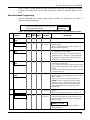
Table of Contents
• • • • • • • • • • • • • • • • • • • • • • • • • • • • • • • • • • • • • • • • • • • • • • • • •
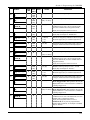
SECTION 1: General Information ........................................................................................................... 1-1
System Overview .......................................................................................................................................................1-1
Introduction.........................................................................................................................................................1-1
General Information............................................................................................................................................1-1
System Features .........................................................................................................................................................1-1
Modes of Operation ............................................................................................................................................1-1
ECP Mode....................................................................................................................................................1-1
Zone Trigger Mode......................................................................................................................................1-2
4204 Mode and Two-4204 Mode ................................................................................................................1-2
Module Supervision Features..............................................................................................................................1-2
Antenna...............................................................................................................................................................1-3
Specifications .............................................................................................................................................................1-3
Mechanical..........................................................................................................................................................1-3
Electrical .............................................................................................................................................................1-3
RF .......................................................................................................................................................................1-3
Environmental.....................................................................................................................................................1-3
SECTION 2: Mounting and Wiring.......................................................................................................... 2-1
Mounting the 7845GSM ............................................................................................................................................2-1
Wiring the 7845GSM.................................................................................................................................................2-2
Wiring for ECP, 4204 and Two-4204 Modes .....................................................................................................2-2
Wiring for Zone Trigger Mode ...........................................................................................................................2-3
Wiring for Module Fault Relay...........................................................................................................................2-4
Power Connections and Options ................................................................................................................................2-5
Backup Battery Connection ................................................................................................................................2-5
Initial Power-Up Sequence .................................................................................................................................2-6
SECTION 3: Programming the 7845GSM .............................................................................................. 3-1
General Information...................................................................................................................................................3-1
Using the AlarmNet Direct website ....................................................................................................................3-1
Using a 7720P Programming Tool......................................................................................................................3-2
Using the Control Panel Programming Mode .....................................................................................................3-2
Programming Conventions .................................................................................................................................3-3
ECP Mode Programming ...........................................................................................................................................3-3
ECP Status Codes ...............................................................................................................................................3-7
Alternative Modes (Zone Trigger, 4204 and Two-4204)...........................................................................................3-7
Zone Trigger Mode .............................................................................................................................................3-7
4204 Emulation Mode.........................................................................................................................................3-8
4204 Emulation Mode Options ...........................................................................................................................3-8
Alternative Mode Programming ................................................................................................................................3-9
WWW.DIYALARMFORUM.COM
WWW.DIYALARMFORUM.COM
i
7845GSM/7845GSMCN Installation and Setup Guide
Exiting Programming Mode.....................................................................................................................................3-16
Setting Factory Defaults ...................................................................................................................................3-16
SECTION 4: Registration .......................................................................................................................... 4-1
Registering the 7845GSM..........................................................................................................................................4-1
Registering through AlarmNet Direct Website...................................................................................................4-1
Using the Tamper Switch....................................................................................................................................4-2
Using the Programming Tool..............................................................................................................................4-2
Replacing an existing module using the programming tool................................................................................4-3
Register by Phone ...............................................................................................................................................4-4
SECTION 5: Programmer Keyboard Commands................................................................................. 5-1
Programmer Keyboard Commands............................................................................................................................5-1
Module Identification Displays...........................................................................................................................5-1
GSM Status Displays ..........................................................................................................................................5-2
System Status Displays .......................................................................................................................................5-2
SECTION 6: Appendices ............................................................................................................................ 6-1
Appendix A: Summary of LED Operation ................................................................................................................6-1
7845GSM Status Display Operation...................................................................................................................6-1
Signal Strength (RSSI) / Mode and Status LEDs................................................................................................6-3
Mode and Status Indicator Switch ......................................................................................................................6-3
Appendix B: Central Station Messages......................................................................................................................6-4
Appendix C: GSM Downloading...............................................................................................................................6-5
General Information............................................................................................................................................6-5
Direct Wire Setup ...............................................................................................................................................6-5
Appendix D: Glossary................................................................................................................................................6-6
Summary of Connections Diagram…………………………………………………………..……….Inside Back Cover
ii
WWW.DIYALARMFORUM.COM
WWW.DIYALARMFORUM.COM
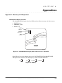
S E C T I O N
1
General Information
• • • • • • • • • • • • • • • • • • • • • • • • • • • • • • • • • • • • • • • • • • • • • • • • •
In This Section
♦ Specifications
♦ System Overview
♦ System Features
• • • • • • • • • • • • • • • • • • • • • • • • • • • • • • • • • • • • • • • • • • • • • • • • •
System Overview
Introduction
Congratulations on your purchase of Honeywell's 7845GSM/7845GSMCN Digital Cellular
Communicator (henceforth referred to as 7845GSM). It represents the latest and most
innovative communication technology for the security industry and uses the most
sophisticated encryption to ensure the highest level of security for your customer.
In addition to alarm reporting, the 7845GSM provides upload/downloading capability of
Honeywell's control panel data via the AlarmNet-G network, using GSM (Global System for
Mobile) technology.
The 7845GSM module requires an AlarmNet–I account. For new installations, please obtain the
account information from the central station prior to programming this module. For replacement
installations, the AlarmNet-I account is created automatically when the module is registered (based on
the existing "C Series" account).
General Information
Honeywell's 7845GSM Cellular Communicator transmits signals to the AlarmNet-G network
(GSM cellular network, which uses GPRS to complete these transmissions) and forwards
them to your central station. If your current Central Station is capable of receiving signals
from AlarmNet central stations, they are capable of receiving signals from the 7845GSM.
If the GPRS network is unavailable, the 7845GSM will attempt to send the transmission via
SMS (Short Message Service).
System Features
Basic features of the 7845GSM include:
• Quick connection to compatible Honeywell series control panels
• Simple programming using a 7720P programming tool
• Reports fire, burg, and status messages via wireless network
• Allows uploading and downloading of control panel data via the wireless network.
Modes of Operation
The 7845GSM provides four modes of operation so it can be used with various types of
control panels, as summarized below:
ECP Mode
• This mode is for use with Honeywell controls that support LRR-ECP communication
• The module connects to the control’s keypad terminals and provides 2-way communication
with the control using ECP messaging
WWW.DIYALARMFORUM.COM
WWW.DIYALARMFORUM.COM
1-1
7845GSM/7845GSMCN Installation and Setup Guide
• The control treats the module as a Long Range Radio (LRR) device, so program the control
accordingly, including setting the module’s proper LRR device address
• Reports are sent in Contact ID format
• The module also supports two hardwire zone trigger inputs (zones 6 and 7)
Zone Trigger Mode
• This mode is for use with controls that do not support LRR-ECP communication nor 4204
Relay Modules
• The module provides six input zones
• Each zone can be configured for +V, -V, or EOLR triggering
• Each zone can be programmed for inverted operation, delayed reporting, and restoral
reporting
• Zone 1 input can distinguish between pulsed and steady signals and report fire or
burglary alarms respectively
• Zone 1 can also be programmed to report Lynx panic (if used with Lynx control)
• Reports are sent in ADEMCO High-Speed format
4204 Mode and Two-4204 Mode
• This mode is for use with Honeywell controls that do not support LRR-ECP
communication, but that do support 4204 Relay Modules
• The module connects to the control’s keypad terminals
• The control treats the module as 4204 Relay Module(s), so program the control
accordingly, including setting the module’s proper 4204 device address
• 4204 mode provides up to four zone inputs, plus two optional trigger zones, depending on
options programmed
• Two-4204 mode provides up to eight zone inputs, depending on options programmed
• Each 4204 zone can be programmed for delayed reporting and restoral reporting
• Reports are sent in ADEMCO High-Speed format
Module Supervision Features
The 7845GSM provides the following types of supervision and module fault detection:
• Network communication failure: In the event the AlarmNet network does not hear a
supervisory message from the module within a specified time (“Supervision” option, 24
hours, 30 days, or none), AlarmNet notifies the central station of a communication failure.
• Communication path failure: In the event the module detects a communication path
failure, the control panel can be notified of a trouble condition with the module after a
specified time has elapsed (“GSM Flt Time” option, 00-99 minutes).
• Fault output: Terminal 11 can serve as a fail-safe trigger for module fault conditions.
If used, the fault relay will trip when the following conditions occur: tamper*, power loss*,
low battery*, battery charger fault*, loss of network connectivity*, the device is not
registered and the device is remotely disabled by AlarmNet.
*Alarm reporting for the noted condition must be enabled for it to trigger the fault relay.
• Primary power loss and low battery conditions (“Pwr Loss Rpt,” “Low Bat Rpt” options).
• Cover tamper condition (“Tamper Rpt” option).
1-2
WWW.DIYALARMFORUM.COM
WWW.DIYALARMFORUM.COM
Section 1: General Information
Antenna
The 7845GSM comes equipped with an internal antenna. This feature provides additional
security to the installation by making the device tamper resistant.
AMPS antennas, such as the 7825-OC antenna, cannot be used with this product.
Specifications
Mechanical
Dimensions: 8.4" x 8.0" x 1.5"
Weight: 2.4 lbs., with battery
Electrical
Input Power: 9VAC, 15VA transformer, Honeywell part number 1332/1332CN in Canada
(included)
Backup Battery: 6V, 3.1AH, Honeywell part number K14139, (included)
Current Drain: 35mA average standby, 500mA peak transmit
Fault Relay Output: Open collector, 12VDC, .25W max.
Input Trigger Levels: (V+) 2V – 13V
(V-) 0V – 1V
RF
Transceiver Type: Tri-Band GSM/GPRS Class 10
Modulation: GMSK
Antenna: Internal GSM quad-band antenna 1.3 dBi gain
Transmission
Frequency
Transmit
Power
Receive
Frequency
Sensitivity
(MHz)
(dBm)
(MHz)
(dBm)
GSM 850
824-849
33
869-894
GSM 1800
1710-1785
33
GSM 1900
1850-1910
33
Band
Receive
Number
of
Channels
Channel
Spacing
Duplex
Separation
(MHz)
(kHz)
-107
124
200
45
1805-1880
-106
374
200
95
1930-1990
-105.5
299
200
80
Environmental
Operating temperature: -20º to +55ºC
Storage temperature: -40º to +70ºC
Humidity: 0 to 90% relative humidity, non-condensing
Altitude: to 10,000 ft. operating, to 40,000 ft. storage
1-3
WWW.DIYALARMFORUM.COM
WWW.DIYALARMFORUM.COM
7845GSM/7845GSMCN Installation and Setup Guide
1-4
WWW.DIYALARMFORUM.COM
WWW.DIYALARMFORUM.COM
S E C T I O N
2
Mounting and Wiring
• • • • • • • • • • • • • • • • • • • • • • • • • • • • • • • • • • • • • • • • • • • • • • • • •
In This Section
♦ Power Connections and Options
♦ Mounting the 7845GSM
♦ Wiring the 7845GSM
• • • • • • • • • • • • • • • • • • • • • • • • • • • • • • • • • • • • • • • • • • • • • • • • •
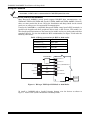
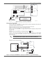
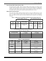
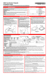
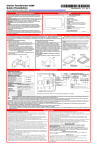
Mounting the 7845GSM
The 7845GSM must be mounted indoors. To mount the 7845GSM, see Figure 1 and
complete the following steps:
1.
Unpack the 7845GSM and detach the case back by pushing up into the two tabs located
at the bottom of the 7845GSM with the blade of a screwdriver while pulling the case
back and case front apart.
2.
Temporarily connect the 7845GSM to the AC transformer, supplied.
3.
Choose the installation site with the best signal strength by observing the signal
strength (RSSI) bar graph (refer to Section 6 for information about signal strength and
status indications). Signal strength should be within 3-5 bars. The best signal strength
is usually found at the highest point in the building, near a window. Unplug the
transformer.
3 BARS MIN.
R
Y
Y
G
G
G
7845i-GSM-025-V0
4.
Locate the case back over the mounting surface such that the opening in the case back
is aligned with the wire/cable access opening (in the mounting surface) while passing
the wires/cable through the opening in the case back, or through the removable
knockouts located on the bottom of the back cover.
5.
Secure the case back to the mounting surface using four screws (supplied).
6.
When all wiring is completed, attach the case front of the 7845GSM to the case back.
Attach the top of the 7845GSM first then press the bottom section inward until it snaps
into place. Secure bottom using cover securing screw (supplied) as shown below,
(required for UL installations).
MOUNTING
SCREW (4)
(TYP)
CASE
BACK
INTERNAL
ANTENNA
WALL OR
MOUNTING
SURFACE
OPTIONAL WIRING
KNOCKOUT
NA
NA
FO
R
EX
OH
TER
AN
L
TEN
ON
LY
CX
MM
M,
50
P
7720
!
T
USE
POR
VICE
R
SER
MME
NE
GRA
PHO
LED
PRO
IT
TELE
NSM
FOR
TRA
NOT
9
-
16.5
FOR
ER:
KUP
VAC BAC
Hr
6
24
MC5
W
CASE
FRONT
AHr
POW
Y267
3.1
IC:
ARY
6V.
Y:
E
PRIM
C56
TER
HER
GIPM
ID:
BAT
C
TX
MA
LAB
RX
EL
FCC
GSM
GPPS
WEB
MODE 2
MODE 1
RSSI
l
el
yw
ne
Ho
OPTIONAL WIRING
KNOCKOUTS
TAB
TAB
COVER SECURING SCREW
7845GSM-015-V0
Figure 1. Mounting the 7845GSM
WWW.DIYALARMFORUM.COM
WWW.DIYALARMFORUM.COM
2-1
7845GSM/7845GSMCN Installation and Setup Guide
Wiring the 7845GSM
Unshielded, 22 AWG cable is recommended for 7845GSM power/data wires.
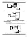
Wiring for ECP, 4204 and Two-4204 Modes
Most Honeywell ADEMCO control panels support LRR-ECP data communication, (e.g.,
VISTA-10P, VISTA-15P, VISTA-20P, LynxR-I, VISTA-128BP and VISTA-128FBP). However,
there are some panels that do not. Check the Installation and Setup Guide for the control
panel you are using to see if it supports ECP communication.
Connect the 7845GSM to a compatible Honeywell VISTA control panel's ECP terminals, in
parallel with keypads and other peripheral devices such as RF receiver, VIP module, etc.
Wire length/gauge limitations are the same for the module as they are for keypads and other
peripheral devices. To wire the module for ECP or 4204 modes, see Figure 2 and make the
following connections:
Table 1. Wiring connections for ECP or 4204 modes
7845GSM
Control
Terminal 3 V+
+12 V Aux
Terminal 4 GND
Ground
Terminal 5 Data In
Data Out
Terminal 6 Data Out
Data In
TRANSFORMER
+12 V AUX
RED
GND
BLK
DATA OUT
YEL
DATA IN
GRN
TB1
1
AC INPUT 1
2
AC INPUT 2
3
ECP (+) VOLTAGE INPUT
4
GND
5
ECP DATA IN
6
ECP DATA OUT
J1
BATTERY
K14139
VISTA CONTROL PANEL
7845GSM
7845GSM-009-V0
Figure 2. Wiring a VISTA for ECP Mode or 4204 Modes
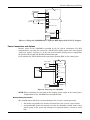
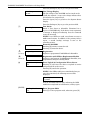
To install a 7845GSM with a LynxR-I Security System, wire the devices as shown in
Figure 3. Refer to the LynxR-I Installation and Setup Guide.
2-2
WWW.DIYALARMFORUM.COM
WWW.DIYALARMFORUM.COM
Section 2: Mounting and Wiring
TB1
1
2
BLK
GRN
YEL
RED
RED
4-WIRE CABLE (N4632-4)
BLK
YEL
GND
DATA IN
NC
+12 VDC
DATA OUT
GRN
4
3
ECP (+) VOLTAGE INPUT
4
GND
5
Z1/Z2 OR DATA IN
6
Z3 OR DATA OUT
LRR/IP COMMUNICATIONS PORT
7845GSM
LYNXR-I CONTROL PANEL
LYNX
STANDARD
CAPACITY
BATTERY
LYNX
(OPTIONAL)
SUPER HIGH
REQUIRED FOR
CAPACITY
24-HR BACKUP
BATTERY
NOTE
DO NOT CONNECT THE 7845GSM BACKUP BATTERY
OR TRANSFORMER
WHEN USING WITH LYNXR-I
7845GSM-028-V0
Figure 3. Wiring a LynxR-I for ECP Mode
Wiring for Zone Trigger Mode
To trip a zone on the 7845GSM in V+ trigger mode, the positive triggering voltage from the
control panel must be within 2.0V-14.5V.
Trigger levels above this range may cause permanent damage to the unit.
Trigger levels below this range result in unreliable operation.
To trip a zone on the 7845GSM in V- trigger mode, the negative triggering voltage must be
less than 1.0V.
NOTE: LynxR and LynxR-EN have a designated trigger for V+ trigger.
Connect a wire from the triggering source (bell output, voltage trigger, etc.) of the control
panel to the zone input of the module, and connect a common ground between the module
and control panel.
UL
The configurations shown in Figures 4 and 5 have not been evaluated by UL.
Examples of zone connections follow:
TB1
1
AC INPUT 1
2
AC INPUT 2
+12 V AUX
3
ECP (+) VOLTAGE INPUT
GND
4
GND
BELL (+)
5
ZONE INPUT Z1/Z2
BELL ( )
CONTROL PANEL
( )
J1
(+)
7845GSM
BATTERY
K14139
7845GSM-012-V0
TRANSFORMER
Figure 4. Wiring the 7845GSM Zone 1 Input for a Positive (+) Triggered Bell Output
WWW.DIYALARMFORUM.COM
WWW.DIYALARMFORUM.COM
2-3
7845GSM/7845GSMCN Installation and Setup Guide
TRANSFORMER
TB1
1
AC INPUT 1
2
AC INPUT 2
+12 V AUX
3
ECP (+) VOLTAGE INPUT
GND
4
GND
BELL (+)
5
ZONE INPUT Z1/Z2
BELL ( )
(+)
( )
J1
7845GSM-013-V0
CONTROL PANEL
7845GSM
BATTERY
K14139
Figure 5. Wiring the 7845GSM Zone 1 Input for a Ground (-) Triggered Bell Output
TRANSFORMER
TB1
1
AC INPUT 1
2
AC INPUT 2
4
GND
5
ZONE INPUT Z1/Z2
9
LRR / AAV
TRIGGER
2K EOL
RESISTOR
8
LYNXR/LYNXR-EN
CONTROL PANEL
J1
7845GSM
BATTERY
K14139
7845-GSM-021-V0
Figure 6. Wiring the 7845GSM Zone 1 Input to a LynxR Trigger Output
Wiring for Module Fault Relay
You may wire and program the module's fault output trigger for fail-safe mode (see the
question "FLT REL ON Y/N").
To sense a module fault at the control panel, make connections as shown in Figure 7,
including the proper EOL resistor required by the control.
TRANSFORMER
TB1
1
AC INPUT 1
2
AC INPUT 2
3
ECP (+) VOLTAGE INPUT
GND
4
GND
ZONE IN (+)
5
Z1/ Z2 or DATA IN
12V AUX
2K EOL
RESISTOR
6
11 RAD FLT
CONTROL PANEL
J1
7845GSM
BATTERY
K14139
7845GSM-007-V0
Figure 7. Wiring the 7845GSM to Trip a Control Panel Zone for Normally Closed Fault
2-4
WWW.DIYALARMFORUM.COM
WWW.DIYALARMFORUM.COM
Section 2: Mounting and Wiring
TB1
TRANSFORMER
2K EOL
RESISTOR
1
AC
2
AC
3
ECP (+) VOLTAGE INPUT
4
GND
5
ZONE INPUT Z1/Z2
N.O.
N.C.
J1
7845GSM
BATTERY
K14139
7845-GSM-030-V0
Figure 8. Wiring the 7845GSM Zone 1 Input for EOL Supervised N.O./N.C. Triggers
Power Connections and Options
Primary power for the 7845GSM is provided by the AC plug-in transformer. For ECP
communication, you must also connect the +12VDC AUX voltage output of the control panel
(9.6V-13.8V typical) (see Figure 9). In the case of the LynxR-I, primary power is supplied by
the LynxR-I unit through the IP/LRR communication port.
In all installations, TB1-4 GND must be connected to ground (GND) on the control panel.
TRANSFORMER
TB1
1
AC INPUT 1
2
AC INPUT 2
12V AUX
3
ECP (+) VOLTAGE
GND
4
GND
5
Z1/ Z2 or DATA IN
11 RAD FLT
CONTROL PANEL
BATTERY
K14139
7845GSM
7845GSM-008-V0
J1
Figure 9. Powering the 7845GSM
NOTE: When calculating the total load on the auxiliary power output of the control panel,
budget 10mA for the 7845GSM when using ECP mode.
Backup Battery Connection
The included battery (K14139) is used for backup in the event of a system power loss.
•
The battery can provide over 24 hours of system life in the event of a power failure.
•
A programmable power loss message can alert the AlarmNet Control Center when
system power is lost (power loss messages are reported within 1-3 hours of actual
loss).
WWW.DIYALARMFORUM.COM
WWW.DIYALARMFORUM.COM
2-5
7845GSM/7845GSMCN Installation and Setup Guide
•
The module transmits a low-battery message (programmable) when the battery
reaches 5.7V ±5%, indicating subsequent message may not be transmitted.
•
The system shuts down when the battery reaches 5.1V, and radio transmissions are
no longer possible.
•
If system power is restored before the module shuts down, a power restore message is
sent within 1-3 hours after power is restored, and the battery is recharged using the
7845GSM’s built-in battery charger. If system power is restored after the 7845GSM
has shut down, a power-on reset condition exists, the module initializes itself and the
battery will recharge.
Install the battery as follows, and refer to the Summary of Connections diagram at the end of
this document.
1. Place the battery inside the case back.
2. Snap the right side of the battery clip onto the inside of the case back and secure the
left side with the screw provided.
1. Do not plug the battery in until after you have powered-up the 7845GSM.
2. If using a LynxR-I, do not connect the module's backup battery. The LynxR-I backup
battery will supply backup power in the event of a power outage.
Initial Power-Up Sequence
Before connecting power, check that the following have been completed:
1. If using ECP Mode, terminal block TB1 V+ and GND terminals are connected to the
control panel’s auxiliary power output: 12VDC nominal.
2. Plug in the transformer (or other main power source). Initially, all 7845GSM
programming options are set to the factory default settings.
3. Connect the red and black battery cables to the battery terminals. Connect battery cable
to connector J1.
4. Power up the control panel.
2-6
WWW.DIYALARMFORUM.COM
WWW.DIYALARMFORUM.COM
S E C T I O N
3
Programming the 7845GSM
• • • • • • • • • • • • • • • • • • • • • • • • • • • • • • • • • • • • • • • • • • • • • • • • •
In This Section
♦ General Information
♦ ECP Mode Programming
♦ Alternative Modes (Zone Trigger, 4204 and
♦ Alternative Mode Programming
♦ Exiting Programming Mode
Two-4204)
• • • • • • • • • • • • • • • • • • • • • • • • • • • • • • • • • • • • • • • • • • • • • • • • •
General Information
The 7845GSM is designed to deliver alarms via the GSM network to an AlarmNet central
station when it is registered with a valid AlarmNet account.
The 7845GSM module requires an AlarmNet–I account. For new installations, please obtain the
account information from the central station prior to programming this module. For replacement
installations, the AlarmNet-I account is created automatically when the module is registered (based on
the existing "C Series" account).
You can program a 7845GSM by one of the following methods:
• Through the AlarmNet Direct website
• Through use of a 7720P Programming Tool
• Through a programming mode in the control panel on panels that support this option
(e.g., VISTA-128BP and FBP)
Using the AlarmNet Direct website
To program the module via the website (if you are already signed up for this service), go to:
https://services.alarmnet.com/AlarmNetDirect/userlogin.aspx
If you are not signed up for this service, click on “Dealer Sign-Up.
Log in and follow the on-screen prompts.
Please have the following information available when programming the module:
1. Primary City ID (two-digit number)
2. Primary Central Station ID (two-digit hexadecimal number)
3. Primary Subscriber ID (four-digit number)
4. MAC ID and MAC CRC number (located on the outside of box and on label inside
module) or MIN number of the device you are replacing
5. Mode of operation of existing module if replacing a "C" series radio.
After programming is complete, you must transfer the data to the module and the module
must be registered. Refer to Section 4: Registration, for further instructions.
WWW.DIYALARMFORUM.COM
WWW.DIYALARMFORUM.COM
3-1
7845GSM/7845GSMCN Installation and Setup Guide
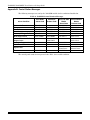
Using a 7720P Programming Tool
Connect the 7720P Programming Tool as shown below. The 7845GSM powers the 7720P
Programming Tool via the programming jack, and automatically senses the presence of the
7720P when it is plugged in.
Xmit
Shift
7720 PROGRAMMING TOOL
A
BS / ESC
B
1
/
3
E
F
6
5
T
S
X
8
7
Shift
C
2
D
4
N /Y
Space
9
Enter
0
#
INTERNAL
ANTENNA
LEDs
7720P
PROGRAMMING
JACK
M1
M0
RSS
I
IBS
GPRS
RSSI / MODE AND
STATUS LEDs
TB1
MODE AND STATUS
INDICATOR SWITCH
TAMPER
SWITCH
J1
BATTERY
CONNECTOR
7845GSM-005-V1
Figure 10. Cable Connections
Each key of the 7720P has two possible functions: a normal function and a Shift function.
To perform a normal key function, simply press the desired key.
To perform a Shift function, press the [shift] key, and then press the appropriate key.
The prompts in this document reflect use of the 7720P Programming Tool. Table 2 below lists
each normal and shift key function.
Table 2. 7720P Normal and Shift Key (shift LED lit) Functions
KEY
BS/ESC
↓/↑
N/Y
SHIFT
1/A
2/B
3/C
4/D
5/E
6/F
7/S
8/T
9/X
SPACE
0
#/ENTER
NORMAL KEY FUNCTION
[BS]: Press to delete entry
SHIFT KEY FUNCTION
[ESC]: Press to quit program mode; also can reset
programming defaults*
[↓]: Scroll down programming
[↑]: Scroll up programming
[N]: Press for "NO" answer
[Y]: Press SHIFT-Y for "YES" answer
Press before pressing a SHIFT key function. Will light SHIFT LED. LED goes out once a key
is pressed. Press again for each SHIFT function desired.
[1]: For entering the number 1
[A]: For entering letter A
[2]: For entering the number 2
[B]: For entering letter B
[3]: For entering the number 3
[C]: For entering letter C
[4]: For entering the number 4
[D]: For entering letter D
[5]: For entering the number 5
[E]: For entering letter E
[6]: For entering the number 6
[F]: For entering letter F
[7]: For entering the number 7
[S]: For entering letter S
[8]: For entering the number 8
[T]: For entering letter T
[9]: For entering the number 9
[X]: For entering letter X
[SPACE]: For scrolling option list
No SHIFT function
[0]: For entering the number 0
No SHIFT function
[#/ENTER]: Starts programming mode;
No SHIFT function
Press to accept entries
*Active only when the "Exit Programming Mode" prompt is displayed.
Using the Control Panel Programming Mode
Some control panels support programming of the 7845GSM through the control panel
programming mode (e.g., Vista-128BP). If programming through the control panel, only
the ECP Mode programming options are available. The "mode" questions will not be
displayed, and the mode cannot be changed. For a description of key functions on the
3-2
WWW.DIYALARMFORUM.COM
WWW.DIYALARMFORUM.COM
Section 3: Programming the 7845GSM
control panel keypad, and how they map to the 7720P Programming tool, refer to the
control panel's Programming Guide.
Programming Conventions
Programming is accomplished by answering a series of prompts (questions). Most prompts
require only a [Y]es or [N]o response, while others require a numerical response (ID
numbers, etc.).
The current value is displayed on the second line in parentheses ( ). A "?" indicates an
invalid entry.
Use the [ENTER] key to accept the current entry and proceed to the next prompt. If the
entered value is invalid, pressing [ENTER] re-displays the prompt; the next prompt is not
displayed until a valid answer is entered.
Use the up/down arrow keys to scroll through the programming questions without changing
any values. Press the [ESC] key to go to the end of the list of questions.
ECP Mode Programming
The 7845GSM supports ECP messaging to communicate with the control panel. LRRenabled control panels send Contact ID format alarms to the 7845GSM directly on the 4-wire
console bus. Not all control panels support the LRR interface on ECP, so be sure to check the
Installation and Setup Guide of the control panel to see if it supports this feature.
Refer to Table 3 for ECP Mode programming and follow the prompts.
Press the [ENTER] key to begin programming.
NOTE: The central station can remotely block access to local
device programming. If this has been done, the
following prompt appears:
Access to Prog
Mode Denied
NOTE: The default programming values for ECP mode are listed in the prompts below.
Table 3: Programming a 7845GSM for ECP mode only.
PROMPTS
ENTRY
OPTIONS
[Y], [N]
DESCRIPTION
Enters programming mode.
1
Strt Prog Mode?
(Y/N)_
2
Enter Password
[0-9, A-F, N,
S, T, X, Y]
If a password has been previously assigned, this
prompt appears.
Enter a 4-digit password (0-9, A-F, N, S, T, X, Y).
The next prompt appears.
3
Program 7845?
(Y/N)_
[Y], [N]
4
Create Password?
(Y/N)_
[Y], [N]
5
Change Password?
[Y], [N]
To begin programming the module, press [Y] and go to
Prompt 9: "Device Mode."
To create a password if none has been assigned, press
[N] and go to Prompt 4: "Create Password."
To change an existing password, press [N] and go to
Prompt 5: "Change Password."
Passwords can be used to protect account and
programming information.
If no password has been assigned, this prompt appears
after pressing [N] at the "Program 7845?" prompt.
If a password is desired, press [Y] and go to Prompt 6:
"Enter Password."
If a password has already been assigned, this prompt
appears after pressing [N] at the "Program 7845?"
prompt.
Press [Y] if you want to change the password.
NOTE: To clear an existing password, without
entering a new one, answer [Y] to the "Change
Password?" prompt, then press the [Enter] key when
prompted for the new password and its confirmation.
(Y/N)_
WWW.DIYALARMFORUM.COM
WWW.DIYALARMFORUM.COM
3-3
7845GSM/7845GSMCN Installation and Setup Guide
PROMPTS
ENTRY
6
Enter Password
OPTIONS
[0-9, A-F, N,
S, T, X, Y]
7
Verify Password
[0-9, A-F, N,
S, T, X, Y]
DESCRIPTION
This prompt is displayed if [Y] was pressed in Prompt 4
or 5.
Enter a 4-digit password (0-9, A-F, N, S, T, X, Y).
Re-enter the password as confirmation.
If the password doesn't match the first entry, the
following is displayed followed by the "Exit Prog.
Mode?" prompt:
Verify Not OK
PSWD not created
8
9
Exit Prog. Mode?
(Y/N)_
[Y], [N]
Device Mode
(ECP)_
• ECP
• Zone Trig.
• 4204 Emu
• Two 4204s
[ESC]
Otherwise, the "Exit Prog. Mode?" prompt is displayed
directly.
Exits program mode.
Press [N] to go back to Prompt 3.
Press [ESC] to load factory defaults.
Refer to the Exiting Programming Mode paragraph in
this section.
Press the [space] key to scroll through the modes of
operation. Press [ENTER] to select ECP mode.
See Table 5 if programming other modes.
Important Information Regarding Primary and Secondary Accounts (Questions 10-16)
Account information is provided by the central station administrator. If the control supports secondary account
reporting, you will need secondary account information. The City ID, CS ID or Subscriber ID of the secondary
account must differ from that of the primary account.
3-4
10
Primary City ID
(??)_
[01-99]
Enter the 2-digit primary city ID, 01-99 (decimal).
11
Primary CS ID
(???)
[01-FE]
Enter the 2-digit primary central station ID number,
01-FE (HEX).
12
Primary Sub ID
(????)
[0001-9999]
Enter the 4-digit subscriber account number, 00019999 (decimal).
13
En. 2
(N)_
[Y], [N]
Applicable only if control supports Central Station #1
and #2 Category Enable reporting for the LRR device
(e.g., VISTA-128BP, FA1660C, etc.).
Used if reporting to a second central station is desired.
If [N], go to Prompt 17: "Device Address."
14
2 City ID
(??)_
[01-99]
Enter the 2-digit secondary city ID, 01-99 (decimal).
15
2 CS ID
(??)_
[01-FE]
Enter the 2-digit second central station's ID number,
01-FE (HEX).
16
2 Sub ID
(????)_
[0001-9999]
Enter the 4-digit subscriber account number for the
second central station, 0001-9999.
17
Device Address
(03)_
[01-30]
In ECP mode, the 7845GSM communicates with the
panel as a Long Range Radio (LRR) device. Enter the
appropriate ECP device address. For VISTA-10 and
VISTA-20 series control panels, use address 03. For
other controls, see the control panel’s Installation and
Setup Guide.
NOTES:
1. When programming the control, enable the LRR
output.
2. The device address must be unique from the
"Direct Wire Addr" entered in Prompt 19.
nd
CS Y/N
nd
nd
nd
WWW.DIYALARMFORUM.COM
WWW.DIYALARMFORUM.COM
Section 3: Programming the 7845GSM
PROMPTS
ENTRY
OPTIONS
DESCRIPTION
Applies only to VISTA-128BP/250BP and FBP Series
controls.
Enables Direct Wire Downloading over GSM.
If [N], skip to Prompt 20: "Supervision."
18
Enable DW Y/N
(N)_
[Y], [N]
19
Direct Wire Addr
(28)_
[01-30]
When using Direct Wire downloading, the 7845GSM
communicates with the panel as an alpha keypad to
initiate the direct wire download session. Enter the
appropriate device address.
NOTES:
1. This address must also be programmed as an
alpha keypad in the control panel (Device
Programming Mode). DO NOT connect an actual
keypad (or any other device) assigned to this
address.
2. This address must be unique from the "Device
Address" entered in Prompt 17.
20
Supervision
(24 Hours)_
• 30 Day
• 24 Hour
• None
The AlarmNet network must hear at least one
supervisory message from the module during this
supervision period; otherwise, AlarmNet notifies the
central station that a communication failure has
occurred. (If the supervision period is changed after
registration, you must re-register the module.)
Press the [space] key to scroll through choices.
21
22
Old Alarm Time
(10 Minutes)_
GSM Flt Time
(60 mins)_
•10 Minutes
• 15 Minutes
• 30 Minutes
• 1 Hour
• 2 Hours
• 4 Hours
• 8 Hours
• 12 Hours
• 24 Hours
The old alarm time sets how long an undeliverable
alarm is retried for delivery to the central station. If
the message is not validated, it is retried until the old
alarm time is reached or the message is validated.
[01-99]
In the event the module detects a communication path
failure, enter the time delay (in minutes) before the
module notifies the control panel with a trouble
message (and trips the Fault Output if used; (terminal
11) see next prompt). The control panel can then notify
the central station.
[00] = not used
Press the [space] key to scroll through choices.
UL NOTE: Must be two (02) minutes.
23
Flt Rel ON Y/N
(N)_
[Y], [N]
If enabled, the fault open collector output is normally
energized to ground, and de-energizes (open circuit) in
the event of a module fault. For conditions that trip the
fault relay refer to Module Supervision Features in
Section 1.
Set to [Y] if fail-safe mode is desired.
See Wiring for Module Fault Relay in Section 2.
UL NOTE: Must be set to "Y."
24
Pwr Loss Rpt Y/N
(Y)_
[Y], [N]
Sends a primary power loss report to the central
station within 1-3 hours after its detection. A restore
report is sent within 1-3 hours after power is restored.
UL NOTE: Must be set to "Y."
WWW.DIYALARMFORUM.COM
WWW.DIYALARMFORUM.COM
3-5
7845GSM/7845GSMCN Installation and Setup Guide
PROMPTS
25
26
ENTRY
Low Bat Rpt Y/N
(Y)_
Tamper Rpt Y/N
(Y)_
OPTIONS
[Y], [N]
[Y], [N]
DESCRIPTION
Sends a low-battery report when a low battery
condition exists.
UL NOTE: Must be set to "Y" unless used with
LynxR-I series controls. Must be set to "N" when using
LynxR-I series controls.
Sends a tamper report when the module detects a
tamper condition. A tamper restore is automatically
sent when the tamper condition clears.
UL NOTE: Must be set to "Y."
Important Information Regarding Zone Input Options
ECP mode supports two optional hardwire zone input triggers by making connections to the module’s zone 6 and/or
zone 7 terminals and programming the appropriate zone trigger options below.
Each zone input can be programmed to cause an alarm under one of the following conditions:
• (V+), where a positive voltage causes an alarm for normally low connections (voltage trigger, NO, NC)
• (V–), where a ground trigger causes an alarm for normally high connections (open collector, NO, NC)
• (EOLR) End of Line Resistor, where the input is supervised by a 2K EOL resistor. The zone can be triggered
by open collector, voltage trigger, NO, NC.
In addition to the above, zones can be programmed for an Inverted Trigger, where the alarm and normal states of
the zones are inverted; this can serve a fail-safe supervisory purpose for certain installations.
These zone inputs can also be programmed for restore reporting, and for delayed reporting, which allows time for
the user to abort false alarms.
NOTE: Optional hardwire zones report in ADEMCO High-Speed format.
Enable Zn6 Y/N
(N)_
[Y], [N]
Zn6 Trigger Type
(V+)_
• (V+)
• (V–)
• (EOLR)
29
Invert Zn6 Y/N
(N)_
[Y], [N]
30
Restore Zn6 Y/N
(Y)_
[Y], [N]
31
Delay Zn6 (secs)
(00)_
[01-15]
32
Enable Zn7 Y/N
(N)_
[Y], [N]
Enables alarm reporting for zone 7.
If [N], skip to Prompt 37: "Review."
33
Zn7 Trigger Type
(V+)_
• (V+)
• (V–)
• (EOLR)
Selects the triggering method for this zone input.
Press the [space] key to scroll through choices.
34
Invert Zn7 Y/N
(N)_
[Y], [N]
Inverts the alarm and normal states of the zone 7
trigger; otherwise uses normal input signal.
35
Restore Zn7 Y/N
(Y)_
[Y], [N]
36
Delay Zn7 (secs)
(00)_
[01-15]
[00] = no delay
27
28
3-6
Enables alarm reporting for zone 6.
If [N], skip to Prompt 32: "Enable Zn7."
Selects the triggering method for this zone input.
Press the [space] key to scroll through choices.
Inverts the alarm and normal states of the zone 6
trigger; otherwise uses normal input signal.
Enables restore reporting for zone 6.
Defines the reporting delay in seconds for zone 6.
[00] = no delay
Enables restore reporting for zone 7.
Defines the reporting delay in seconds for zone 7.
WWW.DIYALARMFORUM.COM
WWW.DIYALARMFORUM.COM
Section 3: Programming the 7845GSM
PROMPTS
37
ENTRY
Review? Y/N
OPTIONS
[Y] = review
[N] = exit
DESCRIPTION
Reviewing Programming Mode Entries
To review the programming options (to ensure that the
correct entries have been made), press [Y]. The
programming prompts are displayed again. Use the
up/down arrow keys to scroll through the program
fields without changing any of the values. If a value
requires change, simply type in the correct value. When
the last field is displayed, the “REVIEW?” prompt
again appears.
To exit the programming mode, press [N] in
response to the "REVIEW?" prompt, and refer to
Exiting Programming Mode paragraph at the end of
this section.
ECP Status Codes
When the 7845GSM is configured for ECP mode, it sends status messages to the control
panels for battery, power, tamper, and network connectivity failures. Some of the control
panels, (e.g., VISTA-10P, VISTA-15P and VISTA-20P Series) display these on the keypad as
“LngRng Radio” followed by a 4-digit code (listed in Table 4). In addition, the Contact ID
codes (listed in Appendix A) for these conditions are sent to the central station by the
module.
Table 4. Common ECP Keypad Display Status Codes
STATUS CODE
DESCRIPTION
0000
Control panel lost communication with 7845GSM.
0880
7845GSM tamper detected (cover removed).
0005
7845GSM has lost contact with AlarmNet-G network.
000F
7845GSM is not registered; account not activated.
0019
7845GSM shutdown.
0400
7845GSM power-on reset AND the control panel lost communications with
7845GSM.
0C80
7845GSM power on reset AND tamper detected.
0C8F
7845GSM power on reset AND tamper detected AND not registered.
08E0
7845GSM tamper detected and 7845GSM battery low.
3000
Primary power loss (will only be displayed in conjunction with another event).
8000
Battery charger failure (will only be displayed in conjunction with another
event).
0060
Low battery (will only be displayed in conjunction with another event).
Alternative Modes (Zone Trigger, 4204 and Two-4204)
Zone Trigger Mode
There are six input zones available on the 7845GSM. Each zone is selectable for +V, -V, or
EOLR trigger. The first zone input can detect both pulsed and steady signals if connected to
a bell output. Additionally, the first zone input can be programmed to detect a single pulse
(characteristic of a Panic indication on the Lynx, LynxR or LynxR-EN control panel by
enabling the Lynx Panic option). If the programming option “Lynx Panic” is enabled, the
7845GSM reports an alarm on zone 3. No restores are reported for this zone. If this option is
selected, the second physical zone input is ignored.
WWW.DIYALARMFORUM.COM
WWW.DIYALARMFORUM.COM
3-7
7845GSM/7845GSMCN Installation and Setup Guide
When using Zone Trigger mode, messages are sent in ADEMCO High-Speed format.
Zones 3, 4, 5, 6 and 7 are voltage trigger inputs located on TB1 pins 6-10. If the Lynx Panic
feature is being used, do not connect zone 3 (the second physical zone input).
Refer to Table 5 for Zone Trigger Mode programming and follow the prompts that pertain to
Zone Trigger Mode.
4204 Emulation Mode
In 4204 Emulation Mode, the 7845GSM communicates with a compatible Honeywell VISTA
series or First Alert control panel as though it were a 4204 Relay Module. If two 4204s are
enabled in the module, it acts as two 4204s at consecutive device addresses. The control
panel must be configured to recognize one or two 4204 relay modules accordingly. On
VISTA-32FB (or higher) control panels and First Alert equivalents, addresses 6 and 13
should not be used when the secondary 4204 is enabled. Messages are sent in ADEMCO
High-Speed format.
NOTE: See your control panel Installation and Setup Guide for the number of 4204 modules
supported. The LynxR-I does not support 4204 mode.
4204 Emulation Mode Options
For control panels that do not support LRR-ECP communication, the 4204 Emulation modes
provide a means of sending up to eight unique reports based on defined system conditions. In
4204 mode, the 7845GSM functions as a logical 4204 Relay Module, where each relay
number, referred to in the module as zone number, can be programmed to send a report
based on the output function programmed in the control for that relay. Each relay-zone can
also be programmed to send a restore message of the reported condition, can be set to delay
transmission of messages, and can be programmed to send reports only when a conditional
zone is triggered (armed), (see Zone Input Options later in this section).
In single 4204 mode, the 7845GSM supports up to four relay-zones. In Two-4204 mode, the
7845GSM functions as two 4204 modules, supporting up to eight relay-zones.
4204 Relay Outputs map to 7845GSM zones as follows:
Second 4204 Zones
First 4204 Zones
(device address entered in Prompt 13):
(device address entered in Prompt 13, plus 1):
Relay 1 = Zone 1
Relay 2 = Zone 2
Relay 3 = Zone 3
Relay 4 = Zone 4 or conditional zone trigger if
“report only if armed” is selected in any zone 1-3
when using single 4204 mode.
NOTE: Zone 4 status is not reported when
being used as the conditional (arming) trigger
zone.
Relay 1 = Zone 5
Relay 2 = Zone 6
Relay 3 = Zone 7
Relay 4 = Zone 8 or conditional zone trigger if
“report only if armed” is selected in any
zone 1-7 when using Two-4204 mode.
NOTE: Zone 8 status is not reported when being
used as the conditional (arming) trigger zone or if
tamper reporting is enabled.
When using the 7845GSM in 4204 Emulation Mode, DO NOT enable the Long-Range Radio
module reporting in the control panel programming. Instead, enable the module device
address(es) and program the appropriate relay activation functions for the relay-zones being
used. In some control panels, it is called “relay programming” and in others it is called “output
device programming.” It is recommended that “close and stay closed” (usually choice 2) action
is selected. Selection of momentary activation will cause the 7845GSM to generate an alarm
and NOT a restore, even if the 7845GSM is programmed to send a restore for the given zone.
In 4204 mode, messages are reported in ADEMCO High-Speed format. Zone alarms
(status 7) are reported with “1” (alarm) or “3” (restore) displayed in the zone position for the
respective zone (e.g. alarm on zone 2: 5155 5555 7; restore 5355 5555 7). A supervision fault
trouble message is automatically sent if the module detects no activity on its connection to
the control. The message is: 5555 5515 5; restore message is: 5555 5535 5.
3-8
WWW.DIYALARMFORUM.COM
WWW.DIYALARMFORUM.COM
Section 3: Programming the 7845GSM
Refer to Table 5 for 4204 Emulation Mode programming and follow the prompts that pertain
to 4204 or Two-4204 mode. Check marks (✔) indicate whether the prompt applies to that
mode.
Alternative Mode Programming
Press the [ENTER] key to begin programming and follow the prompts for the mode of
operation being programmed.
NOTE: The central station can remotely block access to
local device programming. If this has been done,
the following prompt appears:
Access to Prog
Mode Denied
Table 5: Programming a 7845GSM for Zone Trigger, 4204 Emulation, or Two-4204 Emulation modes.
PROMPTS
ZONE
TRIG.
4204/
2-4204
ENTRY
OPTIONS
DESCRIPTION
1
Strt Prog Mode?
(Y/N)_
✔
✔
[Y], [N]
Enters programming mode.
2
Enter Password
✔
✔
[0-9, A-F, N,
S, T, X, Y]
If a password has been previously assigned, this
prompt appears.
Enter a 4-digit password (0-9, A-F, N, S, T, X, Y).
The next prompt appears.
3
Program 7845?
(Y/N)_
✔
✔
[Y], [N]
To begin programming the module, press [Y] and
go to Prompt 9: "Device Mode."
To create a password if none has been assigned,
press [N] and go to Prompt 4: "Create Password."
To change an existing password, press [N] and go
to Prompt 5: "Change Password."
4
Create Password?
(Y/N)_
✔
✔
[Y], [N]
5
Change Password?
(Y/N)
✔
✔
[Y], [N]
Passwords can be used to protect account and
programming information.
If no password has been assigned, this prompt
appears after pressing [N] at the "Program 7845?"
prompt.
If a password is desired, press [Y] and go to Prompt
6: "Enter Password."
If a password has already been assigned, this
prompt appears after pressing [N] at the "Program
7845?" prompt.
Press [Y] if you want to change the password.
NOTE: To clear an existing password, without
entering a new one, answer [Y] to the "Change
Password?" prompt, then press the [Enter] key
when prompted for the new password and its
confirmation.
6
Enter Password
✔
✔
[0-9, A-F, N,
S, T, X, Y]
If [Y] was pressed in Prompt 4 or 5, this prompt
appears.
Enter a 4-digit password (0-9, A-F, N, S, T, X, Y).
7
Verify Password
✔
✔
[0-9, A-F, N,
S, T, X, Y]
Re-enter the password as confirmation.
If the password doesn't match the first entry, the
following is displayed followed by the "Exit Prog.
Mode?" prompt:
Verify Not OK
PSWD not created
Otherwise, the "Exit Prog. Mode?" prompt is
displayed directly.
WWW.DIYALARMFORUM.COM
WWW.DIYALARMFORUM.COM
3-9
7845GSM/7845GSMCN Installation and Setup Guide
ZONE
TRIG.
4204/
2-4204
Exit Prog. Mode?
(Y/N)_
✔
✔
Device Mode
(ECP)_
✔
PROMPTS
8
9
ENTRY
OPTIONS
[Y], [N]
[ESC]
✔
• ECP
• Zone Trig.
• 4204 Emu
• Two 4204s
DESCRIPTION
Exits program mode.
Press [N] to go back to Prompt 3.
Press [ESC] to load factory defaults.
Refer to the Exiting Programming Mode paragraph
in this Section.
Press the [space] key to scroll through the modes of
operation.
Press [ENTER] to select the mode of operation.
See Table 3 for ECP mode programming.
Important Information Regarding Primary Account (Questions 10-12)
Account information is provided by the central station administrator.
10
Primary City ID
(??)_
✔
✔
[01-99]
Enter the 2-digit primary city ID, 01-99 (decimal).
11
Primary CS ID
(???)
✔
✔
[01-FE]
Enter the 2-digit primary central station ID
number, 01-FE (HEX).
12
Primary Sub ID
(????)
✔
✔
[0001-9999]
Enter the 4-digit subscriber account number, 00019999 (decimal).
13
Device Address
(12)_
✔
[01-15]
The 7845GSM communicates with the control
panel as a 4204 relay module. Enter the
appropriate address. For VISTA-10P and
FA130CP Series control panels, this must be
address 12. For other controls, see the control
panel’s Installation and Setup Guide.
NOTES:
1. The 4204 protocol limits address range to 01-15.
If using 2-4204 mode, the 7845GSM assigns the
second 4204 to the next higher device address
(e.g., if entering address 12 for the first 4204,
then address 13 is automatically assigned to the
second 4204 module). Program the control panel
accordingly.
2. The device address(es) must be unique from the
"Direct Wire Addr" entered in Prompt 15 and
any other address used on the control panel.
14
Enable DW Y/N
(N)_
✔
[Y], [N]
Applies only to VISTA-128BP/250BP and FBP
Series controls, and FA1660C and 1700C Series
controls.
Enables Direct Wire Downloading over GSM.
If [N], skip to Prompt 16: "Supervision."
15
Direct Wire Addr
(28)_
✔
[01-30]
When using Direct Wire downloading, the
7845GSM communicates with the panel as an
alpha keypad to initiate the direct wire download
session. Enter the appropriate device address.
NOTES:
1. This address must also be programmed as an
alpha keypad in the control panel (Device
Programming Mode). DO NOT connect an
actual keypad (or any other device) assigned to
this address.
2. This address must be unique from the "Device
Address" entered in Prompt 13, and cannot
equal that device address plus 1 (one) if using
2-4204 mode.
3-10
WWW.DIYALARMFORUM.COM
WWW.DIYALARMFORUM.COM
Section 3: Programming the 7845GSM
PROMPTS
ZONE
TRIG.
4204/
2-4204
ENTRY
OPTIONS
16
Supervision
(24 Hours)_
✔
✔
• 30 Day
• 24 Hrs
• None
17
Old Alarm Time
(10 Minutes)_
✔
✔
• 10 Min
• 15 Min
• 30 Min
• 1 Hr
• 2 Hrs
• 4 Hrs
• 8 Hrs
• 12 Hrs
• 24 Hrs
[01-99]
18
GSM Flt Time
(60 mins)_
✔
✔
[00] = not
used
DESCRIPTION
The AlarmNet network must hear at least one
supervisory message from the module during this
supervision period; otherwise, AlarmNet notifies
the central station that a communication failure
has occurred. (If the supervision period is changed
after registration, you must re-register the
module.)
Press the [space] key to scroll through choices.
UL NOTE: Must be set to 24 hours.
Sets how long an undeliverable alarm is retried for
delivery to the central station. If the message is not
validated, it is retried until the old alarm time is
reached or the message is validated.
Press the [space] key to scroll through choices.
UL NOTE: Must be set to 10 minutes.
In the event the module detects a communication
path failure, enter the time delay (in minutes)
before the module notifies the control panel with a
trouble message (and trips the Fault Output if
used (terminal 11); see next question). The control
panel can then notify the central station.
UL NOTE: Must be two (02) minutes.
19
Flt Rel ON Y/N
(N)_
✔
✔
[Y], [N]
If enabled, the fault open collector output is
normally energized to ground, and de-energizes
(open circuit) in the event of a module fault. For
conditions that trip the fault relay refer to Module
Supervision Features in Section 1.
Set to [Y] if fail-safe mode is desired.
See Wiring for Module Fault Relay in Section 2.
UL NOTE: Must be set to "Y".
20
Pwr Loss Rpt Y/N
(Y)_
✔
✔
[Y], [N]
Sends a primary power loss report to the central
station within 1-3 hours after its detection. A
restore report is sent within 1-3 hours after power
is restored.
UL NOTE: Must be set to "Y."
21
22
Low Bat Rpt Y/N
(Y)_
Tamper Rpt Y/N
(Y)_
✔
✔
✔
✔
[Y], [N]
[Y], [N]
Sends a low-battery report when a low battery
condition exists. A low-battery restore is
automatically sent when the low battery condition
clears.
UL NOTE: Must be set to "Y" unless used with
LynxR-I series controls. Must be set to "N" when
using LynxR-I series controls.
Sends a tamper report when the module detects a
tamper condition. A tamper restore is
automatically sent when the tamper condition
clears.
UL NOTE: Must be set to "Y."
WWW.DIYALARMFORUM.COM
WWW.DIYALARMFORUM.COM
3-11
7845GSM/7845GSMCN Installation and Setup Guide
ZONE
TRIG.
PROMPTS
23
Lynx Panic Y/N
(Y)_
4204/
2-4204
ENTRY
✔
OPTIONS
[Y], [N]
DESCRIPTION
Applies only if used with a Lynx, LynxR or
LynxR-EN control LRR trigger connected to the
module's zone terminal.
Reports a Panic alarm on zone 3 when the
module detects a single pulse on zone 1.
No restores are generated for a Panic alarm.
Important Information Regarding Zone Input Options
If desired, 4204 mode supports two optional hardwire zone input triggers by making connections to the module’s zone
6 and/or zone 7 terminals and programming the appropriate zone trigger options below.
NOTE: These triggers are not available when using 2-4204 mode.
Zone Trigger Mode provides six hardwire zone input triggers by making connections to the module’s zone terminals
and programming the appropriate zone trigger options below. Zones are numbered 1-7, with zone 2 serving as a
reporting zone only (see Bell Output Zone below).
Bell Output Zone 1 (and 2): The zone 1 terminal can detect both pulsed and steady signals. If connecting the bell
output to the 7845GSM zone causes a bell fault on the control panel, enable the "Trip Inputs 1or2" option. The
7845GSM reports an alarm on zone 1 (fire) when it detects a pulsed signal and an alarm on zone 2 (burglary) when it
detects a steady signal.
Telco Zone and Open/Close Zone: Dedicated zones can be assigned as the telco fault zone and/or an open/close
(arm/disarm) reporting zone. When triggered, these zones report a telco line fault or open/close report respectively, in
ADEMCO High-Speed format. Connect the appropriate trigger from the control to the selected zone input for each of
these options.
Input Trigger Types: Triggering of each zone input can be programmed to cause an alarm under one of the following
conditions:
• (V+), where a positive voltage causes an alarm for normally low connections (voltage trigger, NO, NC)
• (V–), where a ground trigger causes an alarm for normally high connections (open collector, NO, NC)
• (EOLR) End of Line Resistor, where the input is supervised by a 2K EOL resistor. The zone can be triggered by
open collector, voltage trigger, NO, NC.
Inverted Trigger: Zones can be programmed for inverted trigger, where the alarm and normal states of the zones are
inverted; this can serve a fail-safe supervisory purpose for certain installations.
Restore and Delayed Reports: Zone inputs can be programmed for restore reporting, and for delayed reporting
(allowing time for the user to abort false alarms).
UL NOTE: Zone restoral must be enabled.
Report Only if Armed option: To help eliminate redundant reports, zone alarms can be restricted to report only if a
conditional zone is triggered (armed). If this feature is desired, the conditional zone is automatically used as the
“arming” zone. Connect the appropriate control panel trigger to the conditional (arming) zone. The trigger must be
programmed as necessary in the control panel.
The conditional (arming) zone on the module is a different dedicated zone for each programming mode, as follows:
Mode
Conditional (Arming) Zone
Zone Trigger
7
4204
2-4204
4
8
IMPORTANT: If any zone (zones 1-6 in zone trigger mode, zones 1-3 in 4204 mode, zones 1-7 in 2-4204 mode) is set for
Report Only if Armed, the conditional (arming) zone becomes unavailable for reporting (as it is reserved for the
“arming” trigger connection).
24
3-12
Trip Inputs 1or2
w/Bell Out (N)_
✔
[Y], [N]
Use if the zone 1 connection to the control's bell
output causes a bell fault on the control panel.
NOTES:
1. If used, EOLR trigger type is not available
for zones 1 and 3.
2. Do not use with Lynx controls.
WWW.DIYALARMFORUM.COM
WWW.DIYALARMFORUM.COM
Section 3: Programming the 7845GSM
PROMPTS
ZONE
TRIG.
4204/
ENTRY
OPTIONS
DESCRIPTION
2-4204
25
Telco Zone
(0)_
✔
✔
Zone Trig: [3-7] See "Important Information Regarding Zone
Input Options" on previous page.
4204: [1-4]
Enter the zone number to be used for telco line
fault reports. This zone assignment must be
2-4204: [1-8]
unique from the open/close zone selected in
[0] = not used
Prompt 26.
Zone Trigger Mode: If any zone is
programmed for "report only if armed," zone 7
cannot be used. If Lynx Panic is enabled, zone
3 cannot be used.
4204 Mode: If any zone is programmed for
"report only if armed," zone 4 cannot be used
as a telco zone.
2-4204 Mode: If any zone is programmed for
"report only if armed," or if tamper reporting
is enabled, zone 8 cannot be used.
NOTE: Connect the telco line fault output (or
relay output programmed for "telco line fault") to
the telco zone.
26
Open/Close Zone
(0)_
✔
✔
27
Zn1 Trigger Type
(V+)_
✔
Zone Trig: [3-7] Enter the zone number to be used for open/close
(arm/disarm) reports. This zone assignment
4204 : [1-4]
must be unique from the telco zone selected in
Prompt 25.
2-4204: [1-8]
Zone Trigger Mode: If any zone is
[0] = not used
programmed for "report only if armed," zone 7
cannot be used. If Lynx Panic is enabled, zone
3 cannot be used.
4204 Mode: If any zone is programmed for
"report only if armed," zone 4 cannot be used
as an open/close zone.
2-4204 Mode: If any zone is programmed for
"report only if armed," or if tamper is enabled,
zone 8 cannot be used.
NOTE: Connect an open/close (arm/disarm)
trigger (or relay output) from the control panel to
the open/close zone.
• (EOLR)
Selects the triggering method for this zone input.
• (V+)
Press the [space] key to scroll through choices.
• (V–)
28
Restore Zn1 Y/N
(Y)_
✔
✔
[Y], [N]
Enables restore reporting for zone 1.
29
Delay Zn1 (secs)
(00)_
✔
✔
[01-15]
Defines the reporting delay in seconds for zone 1.
Rpt Zn1 ONLY if
Armed (N)_
✔
30
[00] = no delay
✔
[Y], [N]
Reports alarms on zone 1 ONLY if the
conditional zone (zone 7 in zone trigger mode;
zone 4 in 4204 mode; or zone 8 in 2-4204 mode)
is triggered (armed).
If [N], always reports alarms on zone 1.
31
Invert Zn2 Y/N
(N)_
✔
[Y], [N]
Inverts the alarm and normal states of the zone
2 trigger; otherwise uses normal input signal.
WWW.DIYALARMFORUM.COM
WWW.DIYALARMFORUM.COM
3-13
7845GSM/7845GSMCN Installation and Setup Guide
PROMPTS
ZONE
TRIG.
4204/
ENTRY
OPTIONS
DESCRIPTION
2-4204
32
Restore Zn2 Y/N
(Y)_
✔
✔
[Y], [N]
Enables restore reporting for zone 2.
33
Delay Zn2 (secs)
(00)_
✔
✔
[01-15]
Defines the reporting delay in seconds for zone 2.
Rpt Zn2 ONLY if
Armed (N)_
✔
34
[00] = no delay
✔
[Y], [N]
Reports alarms on zone 2 ONLY if the
conditional zone (zone 7 in zone trigger mode;
zone 4 in 4204 mode; zone 8 in 2-4204 mode) is
triggered (armed).
If [N], always reports alarms on zone 2.
If Lynx Panic is enabled, then skip to Prompt 39: "Rpt Zn3 ONLY if Armed."
Zn3 Trigger Type
(V+)_
✔
36
Invert Zn3 Y/N
(N)_
✔
37
Restore Zn3 Y/N
(Y)_
✔
38
Delay Zn3 (secs)
(00)
✔
Rpt Zn3 ONLY if
Armed (N)_
✔
35
39
• (EOLR)
• (V+)
• (V–)
Selects the triggering method for this zone input.
Press the [space] key to scroll through choices.
[Y], [N]
Inverts the alarm and normal states of the zone
3 trigger; otherwise uses normal input signal.
✔
[Y], [N]
Enables restore reporting for zone 3.
✔
[01-15]
Defines the reporting delay in seconds for zone 3.
[00] = no delay
✔
[Y], [N]
Reports alarms on zone 3 ONLY if the
conditional zone (zone 7 in zone trigger mode;
zone 4 in 4204 mode; zone 8 in 2-4204 mode) is
triggered (armed).
If [N], always reports alarms on zone 3.
4204 mode: If any zone is programmed to
"Report Only if Armed," skip to Prompt 50:
"Enable Zn6."
40
Zn4 Trigger Type
(V+)_
✔
• (EOLR)
• (V+)
• (V–)
Selects the triggering method for this zone input.
Press the [space] key to scroll through choices.
41
Invert Zn4 Y/N
(N)_
✔
[Y], [N]
Inverts the alarm and normal states of the zone
4 trigger; otherwise uses normal input signal.
42
Restore Zn4 Y/N
(Y)_
✔
✔
[Y], [N]
Enables restore reporting for zone 4.
43
Delay Zn4 (secs)
(00)
✔
✔
[01-15]
Defines the reporting delay in seconds for zone 4.
Rpt Zn4 ONLY if
Armed (N)_
✔
44
[00] = no delay
24204
only
[Y], [N]
Reports alarms on zone 4 ONLY if the
conditional zone (zone 7 in zone trigger mode;
zone 8 in 2-4204 mode) is triggered (armed).
If [N], always reports alarms on zone 4.
45
Zn5 Trigger Type
(V+)_
✔
46
Invert Zn5 Y/N
(N)_
✔
3-14
• (EOLR)
• (V+)
• (V–)
[Y], [N]
Selects the triggering method for this zone input.
Press the [space] key to scroll through choices.
Inverts the alarm and normal states of the zone
5 trigger; otherwise uses normal input signal.
WWW.DIYALARMFORUM.COM
WWW.DIYALARMFORUM.COM
Section 3: Programming the 7845GSM
PROMPTS
ZONE
TRIG.
47
Restore Zn5 Y/N
(Y)_
✔
48
Delay Zn5 (secs)
(00)_
✔
Rpt Zn5 ONLY if
Armed (N)_
✔
49
4204/
ENTRY
2-4204
24204
only
24204
only
24204
only
OPTIONS
DESCRIPTION
[Y], [N]
Enables restore reporting for zone 5.
[01-15]
Defines the reporting delay in seconds for zone 5.
[00] = no delay
[Y], [N]
Reports alarms on zone 5 ONLY if the
conditional zone (zone 7 in zone trigger mode;
zone 8 in 2-4204 mode) is triggered (armed).
If [N], always reports alarms on zone 5.
50
Enable Zn6 Y/N
(N)_
4204
only
[Y], [N]
Enables alarm reporting for zone 6.
• (EOLR)
• (V+)
• (V–)
[Y], [N]
Selects the triggering method for this zone input.
Press the [space] key to scroll through choices.
If [N], skip to Prompt 56: "Enable Zn7."
51
Zn6 Trigger Type
(V+)_
✔
4204
only
52
Invert Zn6 Y/N
(N)_
✔
4204
only
53
Restore Zn6 Y/N
(Y)_
✔
✔
[Y], [N]
Enables restore reporting for zone 6.
54
Delay Zn6 (secs)
(00)_
✔
✔
[01-15]
Defines the reporting delay in seconds for zone 6.
Rpt Zn6 ONLY if
Armed (N)_
✔
55
Inverts the alarm and normal states of the zone
6 trigger; otherwise uses normal input signal.
[00] = no delay
✔
[Y], [N]
Reports alarms on zone 6 ONLY if the
conditional zone (zone 7 in zone trigger mode;
zone 4 in 4204 mode; zone 8 in 2-4204 mode) is
triggered (armed).
If [N], always reports alarms on zone 6.
[Y], [N]
Enables alarm reporting for zone 7, if used.
If [N], skip to Prompt 64: "Review."
• (EOLR)
• (V+)
• (V–)
[Y], [N]
Selects the triggering method for this zone input.
Press the [space] key to scroll through choices.
✔
[Y], [N]
Enables restore reporting for zone 7.
Zone Trigger mode: This question will only be
displayed if zone 7 is not used as the conditional
(arming) trigger zone.
✔
[01-15]
Defines the reporting delay in seconds for zone 7.
Zone Trigger mode: This question will only be
displayed if zone 7 is not used as the conditional
(arming) trigger zone.
56
Enable Zn7 Y/N
(N)_
57
Zn7 Trigger Type
(V+)_
✔
4204
only
58
Invert Zn7 Y/N
(N)_
✔
4204
only
59
Restore Zn7 Y/N
(Y)_
✔
60
Delay Zn7 (secs)
(00)_
✔
61
Rpt Zn7 ONLY if
Armed (N)_
4204
only
[00] = no delay
✔
[Y], [N]
Inverts the alarm and normal states of the zone
7 trigger; otherwise uses normal input signal.
Reports alarms on zone 7 ONLY if the
conditional zone (zone 4 in 4204 mode; zone 8 in
2-4204 mode) is triggered (armed).
If [N], always reports alarms on zone 7.
2-4204 mode: If any zone is programmed to
"Report Only if Armed," or if tamper is enabled,
skip to "Review."
WWW.DIYALARMFORUM.COM
WWW.DIYALARMFORUM.COM
3-15
7845GSM/7845GSMCN Installation and Setup Guide
PROMPTS
ZONE
TRIG.
4204/
62
Restore Zn8 Y/N
(Y)_
2-4204
24204
only
63
Delay Zn8 (secs)
(00)_
24204
only
64
✔
Review? Y/N
ENTRY
✔
OPTIONS
DESCRIPTION
[Y], [N]
Enables restore reporting for zone 8.
[01-15]
Defines the reporting delay in seconds for zone 8.
[00] = no delay
[Y] = review
[N] = exit
Reviewing Programming Mode Entries
To review the programming options (to ensure
that the correct entries have been made), press
[Y]. The programming questions are displayed
again. Use the up/down arrow keys to scroll
through the program fields without changing
any of the values. If a value requires change,
simply type in the correct value. When the last
field is displayed, the “REVIEW?” question again
appears.
To exit the programming mode, press [N] in
response to the "REVIEW?" question, and refer
to Exiting Programming Mode below.
Exiting Programming Mode
To exit the programming mode, press [N] in response to the "REVIEW?" question. Then press
[Y] to the "Exit Prog Mode?" question. Upon exiting, the root file is updated to log the
changes made. A message is displayed telling the user that this step is being executed. When
complete, the message "DONE" is displayed to indicate the file was successfully uploaded.
If critical configuration changes were made, such as the mode of operation, the 7845GSM
will reset to ensure that the programming features are enabled.
If the file is not successfully uploaded, one of the following prompts will be displayed. Follow
the steps shown below until the upload is successful.
Display
Description
What to do
Cannot Upload
GSM module is not yet initialized.
Wait for RSSI LEDs to be lit.
Press [Y].
Try Again? Y/N_
Failed to Update
Root File!
Network problem, or you
answered "N" to "Cannot Upload
Try Again?" prompt.
Initiate the Force Server Update
command by pressing the [0] key; refer
to Section 5: Programmer Keyboard
Commands.
Setting Factory Defaults
To reset the programming options to factory-default values, press [ESC] at the "Exit Prog
Mode?" prompt.
Set Default?
Y/N_
Press [Y] to reset factory default values.
Press [N] to cancel this function.
If you press [Y], all programmed values are reset to the original factory settings. PLEASE
NOTE THAT THIS WILL ERASE ANY PASSWORD THAT MAY HAVE BEEN ENTERED.
After pressing [Y], the Create Password prompt appears (see Prompt 4).
3-16
WWW.DIYALARMFORUM.COM
WWW.DIYALARMFORUM.COM
S E C T I O N
4
Registration
• • • • • • • • • • • • • • • • • • • • • • • • • • • • • • • • • • • • • • • • • • • • • • • • •
In This Section
♦ Registering the 7845GSM
♦
• • • • • • • • • • • • • • • • • • • • • • • • • • • • • • • • • • • • • • • • • • • • • • • • •
Registering the 7845GSM
Once you have initialized and programmed the 7845GSM, it must be registered to enable the
account. An unregistered 7845GSM is indicated on the Status Display as: Status lit,
Message slow blinking, and Fault not lit.
STATUS, GREEN
MESSAGE, YELLOW
FAULT, RED
Figure 11. Unregistered 7845GSM Status Display In Normal Operation
Throughout this document, the following key is used to describe LED state:
ON
OFF
FAST BLINK
SLOW BLINK
Figure 12. LED Key
Upon completion of the registration process, a 7845GSM transmits a registration message
and receives a registration validation indicating that the account is now enabled. Wait for
the "Registration Success" message to appear, regardless of the registration method used.
You can register the 7845GSM by one of the following methods:
•
Through the AlarmNet Direct website
•
Through use of the Tamper Switch
•
Through use of a 7720P Programming Tool
•
By phone
Registering through AlarmNet Direct Website
The 7845GSM can be registered through the Alarmnet Direct Website. To program the
module via the website (if you are already signed up for this service), go to:
https://services.alarmnet.com/AlarmNetDirect/userlogin.aspx.
Log in and follow the on-screen prompts.
If you are not signed up for this service, click on “Dealer Signup” from the login screen to
gain access to the Honeywell web-based programming.
Dealer Sign-Up Direct Link: https://services.alarmnet.com/AlarmNetDirectP_Sign-Up.
4-1
WWW.DIYALARMFORUM.COM
WWW.DIYALARMFORUM.COM
7845GSM/7845GSMCN Installation and Setup Guide
You will be instructed how to proceed upon completing the sign-up form. Only one sign-up
per dealer is required. Once an initial user is established, additional logins may be created
by that user.
NOTE: Central Stations sign up by contacting AlarmNet Administration at 800-222-6525
option 3.
Please have the following information available when programming the device:
1. Primary City ID (two-digit number)
2. Primary Central Station ID (two-digit hexadecimal number)
3. Primary Subscriber ID (four-digit number)
4. MAC ID and MAC CRC number (located on outside of box and on label inside
module) or MIN number of the device you are replacing.
5. Mode of operation of existing module if replacing a "C" series radio.
Once module is registered, you may log out of the AlarmNet Direct website.
Using the Tamper Switch
Initiate the registration sequence by clicking the Tamper Switch three times.
You can monitor the registration process by viewing the Status Display. The Message
(yellow) LED and the Status (green) LED will blink slowly in unison while registration is in
progress.
Once the registration has been completed successfully, the 7845GSM enters normal
operating mode; the Status (green) LED goes out and the Message (yellow) LED is lit to
indicate that the power-on / reset message is waiting to be sent. This message will appear at
the receiving station as “E339 8xx”, where “xx” is the ECP device address. The description
may read “Trouble – Exp. Mod. Reset”. If registration is not validated within 90 seconds,
the 7845GSM times out, and the (green) LED will be lit (solid).
The power-on/reset message will be sent in Ademco High-Speed format if the module is
programmed for zone trigger, 4204 or 2x4204 modes.
Using the Programming Tool
The interactive registration feature allows the installer to register the 7845GSM through a
series of keyboard commands on the 7720P Programming Tool. This method of registration
lets the installer monitor the registration process.
4-2
Registering …
Once the installation is complete, press the [↑
↑] key on
the 7720P. The registration message is sent and the
unit waits for the acknowledgment.
Registration
SUCCESS
If this is a new installation and the city, central station,
and customer numbers have been correctly entered, the
7845GSM is registered and this message is displayed.
The 7845GSM is now in full service and available for
alarm reporting to the central station.
WWW.DIYALARMFORUM.COM
WWW.DIYALARMFORUM.COM
Section 4: Registration
Possible Errors
Registration BAD
Timed Out
Displayed if no response to the registration request is
received.
Registration BAD
Pri Sub ID BAD
Indicates the city, central station, or customer number
for the labeled account(s) is not accepted. The ID
information was either entered in error, or the central
station failed to pre-authorize programmed ID numbers
with AlarmNet customer service.
Registration BAD
2nd Sub ID BAD
Indicates the city, central station, or customer number
for the Secondary account is not accepted. The ID
information was either entered in error, or the central
station failed to pre-authorize programmed ID numbers
with AlarmNet customer service.
Registration BAD
Pri&Sec – IDs BAD
Displayed when both primary and secondary subscriber
IDs are invalid.
Registration BAD
Pri ID – Need PIN
Displayed if this is a repair/replacement, or an error was
made in programming the Primary account information
of 7845GSM for an existing account. This prompt
appears for 2 seconds. See the Replacing an existing
module section below for further displays.
Registration BAD
2nd ID – Need PIN
This prompt is displayed if this is a repair/replacement,
or an error was made in programming the Secondary
account information of 7845GSM for an existing account.
This prompt appears for 2 seconds. See the Replacing
an existing module section below for further displays.
Registration BAD
Pri&2nd – Need PIN
This prompt is displayed if this is a repair/replacement,
or an error was made in programming BOTH the
Primary and Secondary account information of
7845GSM for an existing account. This prompt appears
for 2 seconds. See the Replacing an existing module
section below for further displays.
Replacing an existing module using the programming tool
Enter PIN#
This prompt appears after pressing the down arrow [↓
↓]
on the 7720P. Enter a 4-digit alphanumeric PIN number
provided by your central station, your dealer or an
authorized AlarmNet representative.
NOTE: If you are replacing an existing "C Series" radio,
you can enter the last four-digits of the "C Series" MIN
number.
Press the [ENTER] key.
Registering …
The registration message is sent and the unit waits for
acknowledgement.
Registration
SUCCESS
If the PIN is valid, the new 7845GSM is registered and
the old unit unregistered. Additionally, AlarmNet sends
a substitution alarm to the central station.
WWW.DIYALARMFORUM.COM
WWW.DIYALARMFORUM.COM
4-3
7845GSM/7845GSMCN Installation and Setup Guide
Registration BAD
If you entered an invalid PIN, the appropriate message
is displayed depending on which account number is
being replaced (see above for exact wording). The
registration process is repeated.
NOTE: Each attempt causes a substitution alarm to be
sent to the central station.
Register by Phone
You can register the module by calling the AlarmNet Technical Assistance Center (TAC) at
1-800-222-6525.
You will need the following information:
4-4
•
MAC number (found on the label).
•
Subscriber information (provided by the central station), including a city code,
CSID, and a subscriber ID.
•
When instructed to do so, triple-click the tamper switch to complete the registration.
WWW.DIYALARMFORUM.COM
WWW.DIYALARMFORUM.COM
S E C T I O N
5
Programmer Keyboard Commands
• • • • • • • • • • • • • • • • • • • • • • • • • • • • • • • • • • • • • • • • • • • • • • • • •
Programmer Keyboard Commands
Programmer keyboard commands can be used to quickly view your connectivity settings and
options. Most commands require you to press the [shift] key and then the designated
command key. (See the keys designated in red on the 7720P Programming Tool.)
[A]
7845GSM
x.x.xx
Software Revision
mm/dd/yy
"x.x.xx" indicates the installed software Revision.
Mm/dd/yy indicates month, day and year of the
revision.
Module Identification Displays
[B]
MAC xxxxxxxxxxxx
MAC CRC
yyyy
MAC Address
“xxxxxxxxxxxx” indicates the 7845GSM's unique
identification number.
"yyyy" indicates the MAC CRC number. This number is
also found on the label on the module, as well as the
label on the box.
Press the [space] key to go to the next field.
Press the [backspace] key to go to the previous field.
SCID xxxxx xxxxx
xxxxx xxxxx
SCID Display
Displays the identification number assigned to the SIM
card (SCID) in this device.
Press the [space] key to go to the next field.
Press the [backspace] key to go to the previous field.
IMEI
xxxxxxxx
xxxxxx x
IMEI Display
Displays the identification number assigned to the
GSM module in this device.
Press the [space] key to get the MAC Address.
Press the [backspace] key to go to the previous field.
[C]
Mon 01 Jan 2001
05:48:39 am
Time
Retrieves the current date and time from the AlarmNet
network in Greenwich Mean Time (GMT). This display
confirms that the module is in sync with network.
5-1
WWW.DIYALARMFORUM.COM
WWW.DIYALARMFORUM.COM
7845GSM/7845GSMCN Installation and Setup Guide
GSM Status Displays
[E]
PriRSSI GPRS REG
-xxxdbm x
x
GSM Status Display Screen 1
PriRSSI – Primary Site RSSI level in dbm
GPRS – GPRS Service availability where “x” can be:
“Y” if GPRS is available
“N” if GPRS is Not available
REG
– Registration status from radio module where
“x” can be:
N – Not Registered
H – Registered Home
S – Searching
D – Registration Denied
R – Registered Roaming
? – Unknown Registration State
Press the [space] key to go to the next screen.
Press the [backspace] key to go to the last screen.
Cntry Netw LAC
xxx xxx xxxxx
GSM Status Display Screen 2
Cntry – Country Code
Netw – Network Code
LAC – Local area code
Press the [space] key to get to the next screen.
Press the [backspace] key to go to the previous field.
Cell BaseSt Chan
xxxxx
x xxx
GSM Status Display Screen 3
Cell – Base Station ID
BaseSt – Base Station Antenna Sector
Chan – Control Channel in use
Press the [space] key to go to the next screen.
Press the [backspace] key to go to the previous field.
Second Site RSSI
-xxxdbm
GSM Status Display Screen 4
Secondary GSM Site RSSI level in dbm.
Press the [space] key to go to the GSM Status Display
Screen 1.
Press the [backspace] key to go to the previous field.
System Status Displays
[S]
ECP 67 TmPB
Flt
xx 5 ++ OK
ECP Mode
Displays the zone and system fault status.
Press the [space] key to go to the next field.
Press the [backspace] key to go to the previous field.
1234 67 TmPB Flt
5555 xx 5 ++ OK
5-2
4204 Emulation Mode
Displays the zone and system fault status.
Press the [space] key to go to the next field.
Press the [backspace] key to go to the previous field.
WWW.DIYALARMFORUM.COM
WWW.DIYALARMFORUM.COM
Section 5: Programmer Keyboard Commands
12345678 TmPB Flt
5555555x 5 ++ OK
Two-4204 Emulation Mode
1234567 TmPB Flt
5555555 5 ++ OK
Zone Trigger Mode
Bat NLd: x.xxV
Bat Ld: x.xxV
Displays the zone and system fault status.
Press the [space] key to go to the next field.
Press the [backspace] key to go to the previous field.
The status of the 7845GSM can be viewed on the
7720P. The status display includes:
•
Zone input status (1234567) - the
numbers 1-7 represent the 7 mappings of the
zone input, and follow Honeywell's ADEMCO
high-speed format codes:
1 = New Event
5 = Normal
X = Not Enabled
•
Tm – Tamper status follows high-speed
format codes above.
•
P – Represents line voltage as follows:
+ = Power line voltage OK
- = Power line voltage bad and reported
V = Power line voltage bad, not reported
(reporting window not expired)
^ = Power voltage restored, not yet
reported
•
B – Represents battery condition as
follows:
+ = Battery voltage acceptable
- = Battery voltage below 5.7V ±5%
•
Flt – Represents radio faults:
OK = Normal ; No fault
G = No network connectivity over GSM
and fault time has expired.
g = No network connectivity over GSM and
fault time has NOT yet expired.
NOTE: The 7720P will not operate if the power line
voltage is removed.
Battery Voltage Display
The voltage levels of the battery connected to the
7845GSM can be viewed on the 7720P. The first line of
the display shows the voltage level of the battery with
no load The second line of the display shows loaded
battery voltage. An asterisk (*) next to the voltage
indicates that this is below the accepted level.
Press the [space] key to go to the next field.
Press the [backspace] key to go to the previous field.
Battery Charger
OK
Battery Charger Status Display
The status of the battery charger circuit of the
7845GSM can be viewed on the 7720P. The status is
either OK or NOT OK.
Press the [space] key to go to the next field.
WWW.DIYALARMFORUM.COM
WWW.DIYALARMFORUM.COM
5-3
7845GSM/7845GSMCN Installation and Setup Guide
Press the [backspace] key to go to the previous field.
Line Voltage
xx.xxV
Line Voltage Display
The line voltage of the 7845GSM can be viewed on the
7720P. An asterisk (*) next to the voltage indicates that
this is below the accepted level.
Press the [space] key to go back to the System Status
Display.
Press the [backspace] key to go to the previous field.
[T]
Test Msg Sent
Test Alarm
Sends a Test alarm to AlarmNet. Functional for a
registered 7845GSM only. If the device is not registered,
a message is displayed indicating that the command
cannot be executed.
NOTE: If two CSIP’s are used, test alarms are sent to
each central station. In addition, if the primary fails to
report, a second (backup) message is sent to the
secondary station.
[X]
Reset CPU Y/N
Reset the 7845GSM.
Pressing [N] returns to normal mode.
Pressing [Y] resets the device.
[↑
↑]
Registering …
(UP arrow)
[↓
↓]
Enter PIN#
Registration with PIN for Replacement Module
Registers a replacement 7845GSM with AlarmNet, once
programmed, using the existing PIN #.
Force Server Update?
Force Upload of Configuration File to Server
Pressing [Y] will force the device to upload its entire
configuration file to the server.
(DN arrow)
[0]
Registration
Registers a programmed 7845GSM with AlarmNet.
Y/N
Pressing [N] cancels the operation.
NOTE: If the GSM module is not initialized when you
enter this command, the following screen will be
displayed:
Cannot Upload
Try Later! _
Wait for the RSSI LEDs to light, indicating the GSM
module has completed its initialization, and try again.
[ENTER]
5-4
Strt Prog Mode?
Y/N_
Enter Program Mode
Press [Y] to enter program mode; otherwise, press [N].
WWW.DIYALARMFORUM.COM
WWW.DIYALARMFORUM.COM
S E C T I O N
6
Appendices
• • • • • • • • • • • • • • • • • • • • • • • • • • • • • • • • • • • • • • • • • • • • • • • • •
Appendix A: Summary of LED Operation
7845GSM Status Display Operation
The 7845GSM Status Display has three LEDs used to indicate message and device status:
• STATUS, green
• MESSAGE, yellow
• FAULT, red
GREEN
(STATUS)
YELLOW
(MESSAGE)
RED
(FAULT)
7845i-GSM-012-V0
Figure 13. 7845GSM Status Display LEDs with Front Cover Installed
Each LED can have four different states - ON, OFF, FAST BLINK and SLOW BLINK.
Throughout this document, the following key is used to describe LED state:
ON
OFF
FAST BLINK
SLOW BLINK
Figure 14. LED Key
WWW.DIYALARMFORUM.COM
WWW.DIYALARMFORUM.COM
6-1
7845GSM/7845GSMCN Installation and Setup Guide
Table 6. Status Display Operation
LED COLOR
GREEN
LED
STATUS
YELLOW
MESSAGE
RED
FAULT
DESCRIPTION
ON – 7845GSM is NOT registered with AlarmNet.
OFF – 7845GSM is registered with AlarmNet.
FAST BLINK – Download session with Compass in progress.
SLOW BLINK – In unison with yellow LED – Registration in
progress.
ON – Message transmission pending.
QUICK PERIODIC BLINK - Normal
FAST BLINK – Message waiting for network ACK.
SLOW BLINK – Idle, power abnormal.
– In unison with green LED – Registration in
progress.
ON – No contact with network.
OFF– Normal.
SLOW BLINK – Loss of communication with the panel (ECP
fault).
FAST BLINK – No network contact AND loss of communication
with the panel.
FAST BLINK – In unison with the RSSI Bar Graph LEDs –
Hardware Error. Call the AlarmNet Technical
Assistance Center.
ALL
A
B
STATUS, GREEN
STATUS, GREEN
MESSAGE, YELLOW
MESSAGE, YELLOW
FAULT, RED
FAULT, RED
Figure 15. A Registered 7845GSM Status Display (A) and
an Unregistered 7845GSM Status Display in Normal Operating State(B)
1
2
3
4
STATUS, GREEN
MESSAGE, YELLOW
FAULT, RED
Figure 16. LED Sequence for a Registered 7845GSM Message Transmission
6-2
WWW.DIYALARMFORUM.COM
WWW.DIYALARMFORUM.COM
Section 6: Appendices
Signal Strength (RSSI) / Mode and Status LEDs
The Signal Strength (RSSI) / Mode and Status LEDs normally display the module’s signal
strength. LED 1 (red LED on the left) will be lit to indicate that the display is in RSSI mode,
and the other LEDs indicate signal strength (lowest to highest, from left to right) between
the module and the receiving tower. Signal strength should be within 3-5 bars.
Mode and Status Indicator Switch
Press and hold the Mode and Status Indicator Switch to change the LED functions in order
to view the mode of operation and network carrier status. When the switch is held down,
LED 1 (red LED on the left) will be off, and the LEDs from left to right have the following
meanings:
Table 7. LED Functions with Mode and Status Indicator Switch Depressed
Status Indications (Table 7b)
Operation Modes (Table 7a)
LED 1
(red)
LED 2
(yellow)
Off=Mode
and Status
indicator
Operation
Mode (in
combination
with LED 3)
LED 4
(green)
LED 3 (yellow)
Operation Mode (in
combination with
LED 2)
Not Used
LED 5
(green)
LED 6
(green)
GPRS
Service
GSM
Module
Registration
with
Network
Carrier
(see below for specific modes and status indications)
Table 7a. Operation Modes
OPERATION MODE
LED 2
st
(1 yellow)
ECP
Zone
4204
2 - 4204
OFF
ON
OFF
ON
LED 3
yellow)
nd
(2
OFF
OFF
ON
ON
Table 7b. Status Indications
STATUS
LED 4
st
(1 green)
OFF
Normal
No GPRS service
available
SLOW BLINK
–
–
NORMAL
BLINK
–
–
FAST BLINK
–
GPRS in use by device
ON
Not Used
GPRS service available
LED 5
green)
LED 6
rd
(3 green)
nd
(2
GSM module not registered with
network carrier
GSM module registered—second
site available–low signal strength
GSM module registered—second
site available–acceptable signal
strength
GSM module registered—second
site available–excellent signal
strength
GSM module registered—no second
site available
WWW.DIYALARMFORUM.COM
WWW.DIYALARMFORUM.COM
6-3
7845GSM/7845GSMCN Installation and Setup Guide
Appendix B: Central Station Messages
The following messages are sent by the 7845GSM module for the conditions listed below.
Table 8: 7845GSM Central Station Messages
Alarm Condition
ECP Mode
Alarm Code
ECP Mode
Restore Code
Zone and 4204
Modes
Alarm Code
Zone and 4204
Modes
Restore Code
Power On Reset
Tamper
Power Loss
Low Battery
Battery Charger Failure
E339 C08xx*
E341 C08xx*
E337 C08xx*
E338 C08xx*
E314 C08xx*
R341C 08xx*
R337 C08xx*
R338 C08xx*
R314 C08xx*
5551 5555 6
5555 5551 7
1555 5555 6
5155 5555 6
5155 5555 1
5555 5553 7
3555 5555 6
5355 5555 6
5355 5555 1
ECP Supervision
Communication Path
Supervision
Swinger Suppression
Telco
E355 C0000
R355 C0000
5555 5515 5
5555 5535 5
R350 C0951
Open/Close
Test
* xx = 7845GSM Device Address
5555 5555 9
5555 5553 5
0D00 0005 0
5555 5155 6
2 sent in
selected zone
5555 5555 9
The control panel sends its own general code (E353) for a trouble condition.
6-4
WWW.DIYALARMFORUM.COM
WWW.DIYALARMFORUM.COM
5555 5355 6
4 sent in
selected zone
Section 6: Appendices
Appendix C: GSM Downloading
General Information
The 7845GSM can be used to provide high-speed up/downloading to Honeywell VISTA and
LYNXR-I control panels over the GPRS network. This allows site maintenance independent
of central station monitoring, and modification to sites globally. At this time, some control
panels support downloading through the ECP bus and some panels support downloading
through the use of a Direct Wire connection. Residential panels such as the VISTA-20P and
LynxR-I support ECP downloading. Currently, commercial controls such as VISTA-128BP
and FBP support downloading through use of a Direct Wire connection (using the trigger
connections on the control panel).
UL
Downloading may only be performed if a technician is at the site.
Direct Wire Setup
To perform up/downloading using Direct Wire, the 7845GSM requires that Direct Wire
Downloading is enabled (Enable DW), and that the ECP device address on which the
7845GSM communicates with the control panel as a keypad is entered (Direct Wire Address).
Additionally, the 7845GSM must be connected by cable as shown below to the panels listed.
NOTE: This feature is not available if device is set for zone trigger mode.
VISTA-128BP/250BP
FA1660C
J8 CONNECTOR
1
2
3
4
5
6
7
7845GSM
PROGRAMMER
PORT
8
FOR EXTERNAL ANTENNA
50
OHM,
MMCX ONLY
9
WHITE
GREEN
BROWN
GR
OU
ND
BLUE
GR
OU
ND
BLACK
RED
OU
T5
BLUE
K4668WH
RJ 11 CABLE
OU
T6
YELLOW
GR
OU
ND
3
IN
IN
PR
INT
2
ER
DT
R GREY
VIOLET
NU
4142 TR CABLE
Honeywell
GSM
GPPS
WEB
MODE 2
MODE 1
RSSI
TB 1
1
2
3
4
5
6
7
8
9
10
11
PARTS SUPPLIED WITH DOWNLOADER KIT P/N VBPCOMKIT
7845GSM-026-V0
7845GSM
VISTA-128FBP/250FBP
FA1670C /FA1700C
J2 CONNECTOR
9
TO
AUX PWR 1
OUTPUT
+ (TO TERM 11)
- (TO TERM 12)
VIOLET
8
GRAY
7
YELLOW
6
WHITE
5
RED
GREEN
4
T
6
OU
T
2
OU
T
5
OU
T
1
GR
OU
ND
IN
PU
T
1
T
3
BLUE
BROWN
3
OU
7
OU
T
OU
2
8
+ PWR
7
- (GND)
6
RXD
5
not used
4
not used
3
TXD
2
not used
1
not used
PROGRAMMER
PORT
4142 TR CABLE
RED BLUE WHITE
PARTS SUPPLIED WITH DOWNLOADER KIT P/N VFBPCOMKIT
FOR EXTERNAL ANTENNA
50
TB 1
1
2
3
4
5
6
7
8
9
10
11
OHM,
MMCX ONLY
Honeywell
GSM
GPPS
WEB
MODE 2
MODE 1
RSSI
OU
T
4
BLACK
1
4100SM
K14394LF 25-PIN TO RJ11 CABLE
7845GSM-025-V0
Figure 17. Cable Connections for Direct Wire Downloading
WWW.DIYALARMFORUM.COM
WWW.DIYALARMFORUM.COM
6-5
7845GSM/7845GSMCN Installation and Setup Guide
Appendix D: Glossary
AES – Advanced Encryption Standard
DHCP – Dynamic Host Configuration Protocol, which provides a mechanism for allocating IP
addresses dynamically so that addresses can be reused when hosts no longer need them.
DNS – Domain Name System, which is a distributed hierarchical naming system used to
resolve domain names (e.g., www.yahoo.com) into numerical IP addresses (e.g., 204.17.25.1.).
DSL – Digital Subscriber Line
ECP – Enhanced Console Protocol, which is a proprietary communications bus used in
Honeywell VISTA control panels for wiring additional keypads and peripheral devices;
consists of a four-wire data bus (power+/-, data in/out).
Gateway IP Address - A gateway (sometimes called a router) is a computer and/or software
used to connect two or more networks (including incompatible networks) and translates
information from one network to the other. The Gateway IP address is the IP address for the
gateway.
GPRS – (General Packet Radio Service)
GSM – Global System for Mobile communications, which is an international standard for
digital mobile phone systems used for cellular communication.
IMEI – International Mobile Equipment Identity number
IP – Internet Protocol
IP Address – A unique number consisting of four parts separated by periods, sometimes
called a "dotted quad.," for example: 204.17.29.11, assigned to every computer/workstation
connected to the Internet. IP numbers can be "static" (assigned and unchanging) or
"dynamic," assigned via DHCP at each and every startup.
ISDN – Integrated Services Digital Network
ISP – Internet Service Provider
LAN – Local Area Network
MAC Address – Media Access Code; located on the module label.
PPPoE – Point-to-Point Protocol over Ethernet
Subnet Mask - A Subnet is a portion of a network that shares a network address with other
portions of the network, and is distinguished by a subnet number. The Subnet Mask is a 32bit address mask used in IP to indicate the bits of an IP address that are being used for the
subnet address.
TCP/IP – Transmission Control Protocol / Internet protocol
6-6
WWW.DIYALARMFORUM.COM
WWW.DIYALARMFORUM.COM
Section 6: Appendices
Notes:
WWW.DIYALARMFORUM.COM
WWW.DIYALARMFORUM.COM
6-7
7845GSM/7845GSMCN Installation and Setup Guide
FCC AND INDUSTRY CANADA STATEMENT
This device complies with Part 15 of the FCC Rules and RSS210 of Industry Canada.
Operation is subject to the following two conditions: (1) This device may not cause harmful
interference, and (2) this device must accept any interference received, including interference
that may cause undesired operation.
This Class B digital apparatus complies with Canadian ICES-003.
Cet Appareil numérique de la classe B est conforme à la norme NMB-003 du Canada.
FEDERAL COMMUNICATIONS COMMISSION (FCC) STATEMENT
This equipment has been tested to FCC requirements and has been found acceptable for use.
The FCC requires the following statement for your information:
This equipment generates and uses radio frequency energy and if not installed and used
properly, that is, in strict accordance with the manufacturer's instructions, may cause
interference to radio and television reception. It has been type tested and found to comply
with the limits for a Class B computing device in accordance with the specifications in Part
15 of FCC Rules, which are designed to provide reasonable protection against such
interference in a residential installation. However, there is no guarantee that interference
will not occur in a particular installation. If this equipment does cause interference to radio
or television reception, which can be determined by turning the equipment off and on, the
user is encouraged to try to correct the interference by one or more of the following measures:
• If using an indoor antenna, have a quality outdoor antenna installed.
• Reorient the receiving antenna until interference is reduced or eliminated.
• Move the radio or television receiver away from the receiver/control.
• Move the antenna leads away from any wire runs to the receiver/control.
• Plug the receiver/control into a different outlet so that it and the radio or television
receiver are on different branch circuits.
If necessary, the user should consult the dealer or an experienced radio/television technician
for additional suggestions. The user or installer may find the following booklet prepared by
the Federal Communications Commission helpful:
"Interference Handbook"
This booklet is available under Stock No. 004-000-00450-7 from the U.S. Government
Printing Office, Washington, DC 20402.
The user shall not make any changes or modifications to the equipment unless authorized by
the Installation and Setup Guide or User Guide. Unauthorized changes or modifications
could void the user's authority to operate the equipment.
6-8
WWW.DIYALARMFORUM.COM
WWW.DIYALARMFORUM.COM
7845GSM Summary of Connections
INTERNAL
ANTENNA
MOUNTING
HOLE (TYP.)
STATUS LED
MESSAGE LED
FAULT LED
FOR EXTERNAL ANTENNA
50 OHM MMCX ONLY
PRIMARY POWER: 9 - 16.5 VAC
CURRENT: 900mA PEAK, 70mA STANDBY
BATTERY: 8V. 3.1 AHr FOR 24 Hr BACKUP
7720P PROGRAMMER PORT/
PANEL DOWNLOAD PORT
FCC:XXXXXXXXXX
IC: YYYYYYYYYY
M1
M0
IBS
RSSI
GPRS
AC 1
AC 2
NOT USED or 12V DC IN
GND
ZONE INPUT Z1/Z2 or ECP INPUT
ZONE INPUT Z3 or ECP OUTPUT
ZONE INPUT Z4 or NOT USED
ZONE INPUT Z5 or NOT USED
ZONE INPUT Z6 or NOT USED
ZONE INPUT Z7 or NOT USED
FAULT OUTPUT
TB 1
1
2
3
4
5
6
7
8
9
10
11
BLACK
RED
SIGNAL
STRENGTH
(RSSI)/MODE
AND STATUS
LEDs
MOUNTING
HOLE
(UNDER
BATTERY)
MOUNTING HOLE
BLK
BATTERY
CLIP
TAMPER SWITCH
RED
BATTERY
J1
BATTERY
CONNECTOR
TB1
1
2
3
4
5
6
7
8
9
10
11
SIGNAL STRENGTH (RSSI)/
MODE AND STATUS INDICATOR
SWITCH
SCREW
TB1 Wiring for 7845GSM Cellular Communicator
Zone
ECP
4204
2 x 4204
Trigger
Mode
Mode
Mode
Mode
AC 1
AC 1
AC 1
AC 1
AC 2
AC 2
AC 2
AC 2
ECP V+ (RED)
NOT USED
ECP V+ (RED)
ECP V (RED)+
GND (BLK)
GND (BLK)
GND (BLK)
GND (BLK)
ECP IN (YEL)
Z1/Z2
ECP IN (YEL)
ECP IN (YEL)
ECP OUT (GRN)
Z3
ECP OUT (GRN)
ECP OUT (GRN)
NOT USED
Z4
NOT USED
NOT USED
NOT USED
Z5
NOT USED
NOT USED
Z6
Z6
Z6
NOT USED
Z7
Z7
Z7
NOT USED
FLT OUT
FLT OUT
FLT OUT
FLT OUT
WWW.DIYALARMFORUM.COM
WWW.DIYALARMFORUM.COM
7845GSM-006-V0
LIMITED WARRANTY
Honeywell International Inc., acting through its Security & Custom Electronics business ("Seller") 165
Eileen Way, Syosset, New York 11791, warrants its product(s) to be in conformance with its own plans
and specifications and to be free from defects in materials and workmanship under normal use and
service for 24 months from the date stamp control on the product(s) or, for product(s) not having a
manufacturer's date stamp, for 12 months from date of original purchase unless the installation
instructions or catalog sets forth a shorter period, in which case the shorter period shall apply. Seller's
obligation shall be limited to repairing or replacing, at its option, free of charge for materials or labor, any
product(s) which is proved not in compliance with Seller's specifications or proves defective in materials
or workmanship under normal use and service. Seller shall have no obligation under this Limited
Warranty or otherwise if the product(s) is altered or improperly repaired or serviced by anyone other than
Honeywell factory service. Connection of any device(s) to a communication bus of a Honeywell security
system (e.g., keypad bus, polling loop) other than those manufactured or approved by Honeywell shall
void this warranty. For warranty service, return product(s) transportation prepaid, to Honeywell Factory
Service, 165 Eileen Way, Syosset, New York 11791.
THERE ARE NO WARRANTIES, EXPRESS OR IMPLIED, OF MERCHANTABILITY, OR FITNESS FOR
A PARTICULAR PURPOSE OR OTHERWISE, WHICH EXTEND BEYOND THE DESCRIPTION ON
THE FACE HEREOF. IN NO CASE SHALL SELLER BE LIABLE TO ANYONE FOR ANY
CONSEQUENTIAL OR INCIDENTAL DAMAGES FOR BREACH OF THIS OR ANY OTHER
WARRANTY, EXPRESS OR IMPLIED, OR UPON ANY OTHER BASIS OF LIABILITY WHATSOEVER,
EVEN IF THE LOSS OR DAMAGE IS CAUSED BY THE SELLER'S OWN NEGLIGENCE OR FAULT.
Seller does not represent that the product(s) it sells may not be compromised or circumvented; that the
product(s) will prevent any personal injury or property loss by burglary, robbery, fire or otherwise; or that
the product(s) will in all cases provide adequate warning or protection. Customer understands that a
properly installed and maintained alarm system may only reduce the risk of a burglary, robbery, fire, or
other events occurring without providing an alarm, but it is not insurance or a guarantee that such will not
occur or that there will be no personal injury or property loss as a result. CONSEQUENTLY, SELLER
SHALL HAVE NO LIABILITY FOR ANY PERSONAL INJURY, PROPERTY DAMAGE OR OTHER LOSS
BASED ON A CLAIM THAT THE PRODUCT(S) FAILED TO GIVE WARNING. HOWEVER, IF SELLER IS
HELD LIABLE, WHETHER DIRECTLY OR INDIRECTLY, FOR ANY LOSS OR DAMAGE ARISING
UNDER THIS LIMITED WARRANTY OR OTHERWISE, REGARDLESS OF CAUSE OR ORIGIN,
SELLER'S MAXIMUM LIABILITY SHALL NOT IN ANY CASE EXCEED THE PURCHASE PRICE OF THE
PRODUCT(S), WHICH SHALL BE THE COMPLETE AND EXCLUSIVE REMEDY AGAINST SELLER.
This warranty replaces any previous warranties and is the only warranty made by Seller on this
product(s). No increase or alteration, written or verbal, of the obligations of this Limited Warranty is
authorized.
165 Eileen Way, Syosset, NY 11791
Copyright 2006 Honeywell International Inc.
www.honeywell.com/security
ÊK14184V1AŠ
K14184V1 11/06 Rev. A
WWW.DIYALARMFORUM.COM
WWW.DIYALARMFORUM.COM