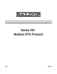
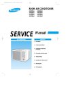
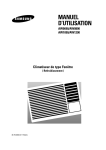
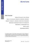
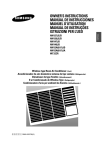
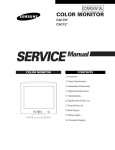
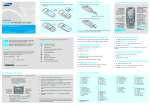
1
AW0690-00162A-front
5/16/00 11:32 AM
Page 2
ROOM AIR CONDITIONER
AW0690
AW0790
AW0890
AW1090
AW1290
AW1890
SERVICE
AIR CONDITIONER
Manual
CONTENTS
1. Precautions
2. Product Specifications
3. Installation and Operating
Instructions
4. Disassembly and Reassembly
5. Troubleshooting
6. Exploded Views and Parts List
7. Block Diagram
8. PCB Diagram
9. Wiring Diagrams
SAM0129
AW0690-00162A-1
5/16/00 11:33 AM
Page 1-1
1. Precautions
1. Warning: Prior to repair, disconnect the
power cord from the circuit breaker.
2. Use proper parts: Use only exact
replacement parts. (Also, we recommend
replacing parts rather than repairing them.)
3. Use the proper tools: Use the proper tools
and test equipment, and know how to use
equipment may cause problems laterintermittent contact, for example.
Fig. 1-1 Avoid Dangerous Contact
4. Power Cord: Prior to repair, check the
power cord and replace it if necessary.
5. Avoid using an extension cord, and avoid
tapping into a power cord. This practice
may result in malfunction or fire.
6. After completing repairs and reassembly,
check the insulation resistance, Procedure:
Prior to applying power, measure the
resistance between the power cord and the
ground terminal. The resistance must be
greater than 30 megohms.
Fig. 1-2 No Tapping and No Extension Cords
7. Make sure that the grounds are adequate.
8. Make sure that the installation conditions
are satisfactory. Relocate the unit if
necessary.
9. Keep children away from the unit while it is
being repaired.
10. Be sure to clean the unit and its surrounding
area.
Fig. 1-3 No Kids Nearby!
Fig. 1-4 Clean the Unit
Samsung Electronics
1-1
AW0690-00162A-1
5/16/00 11:33 AM
Page 1-2
MEMO
1-2
Samsung Electronics
AW0690-00162A-1
5/16/00 11:33 AM
Page 2-1
2. Product Specifications
2-1 Table
Item
Type
Unit of
Measure
AW0690
AW0790
AW0890
AW1090
AW1290
AW1890
600 x 394 x 595
600 x 395 x 595
660 x 425 x 730
Window
-
Dimensions:
(Width X Height X Depth)
mm (inch)
520 x 345 x 485
mm (inch)
571 x 454 x 546
Packing Size
(Width X Height X Depth)
Voltage:
Volt
728 x 459 x 647
723 x 555 x 798
230/208V
115V
Phase
-
Single
Frequency
Hz
60
Operating Current
A
5.6
6.7
7.4
9.2
12.0
8.5/9.1
Power Consumption
W
600
715
800
1,000
1,330
1,800/1,750
Refrigerant Type
Refrigerant Charge
R-22
FREON
g
380
470
500
600
800
1,090
BTU/h
6,000
7,000
8,000
10,000
12,000
18,000/17,500
BTU/HW
10.0
9.8
10.0
10.0
9.0
10.0/10.0
Net Weight
kg
29
29
29
45
45
61
Condenser
Row x Col
2 x 15
3 x 15
3 x 15
3 x 17
3 x 14
3 x 16
2 x 14
2 x 14
3 x 15
Cooling Capacity
EER
Condenser Fan
Evaporator
Evaporator Fan
Propeller-Fan
Type
2 x 14
Row x Col
3 x 14
Blower
Type
Fan Motor
-
IC-9630SWD6C
IC-9630SWD6E
IC-9630SWD6E
AFS090ZREA
AMAFS-100ZREB
AFS140ZTEA
Compressor
-
44A062HS1EB
44A072HW1EB
44080HS1EB
44B102HS1EF
44B124HW1EG(4)
48B175IV1EH
Overload Protect
-
MRA12040-12008
MRA98706-12008 MRA12083-12008
MRA12109-12007 MRA98693-12007
MRA12107-12007
Compressor Capacitor
µF/ VAC
Fan Motor Capacitor
µF/ VAC
30/5µF 370VAC
(Dual Type)
25/5µF 370VAC
(Dual Type)
40/15µF 370VAC 40/15µF 370VAC
(Dual Type)
(Dual Type)
35/6µF 450VAC
(Dual Type)
Fan Speed Control
Samsung Electronics
-
35/6µF 370VAC
(Dual Type)
HIGH, MID, LOW
2-1
AW0690-00162A-1
5/16/00 11:33 AM
Page 2-2
2-2 Dimensions
2-2-1 Main Unit
D
Unit : mm
Model
W
H
D
AW0690
520
345
485
AW0790
520
345
485
AW0890
520
345
485
AW1090
600
394
595
AW1290
600
395
595
AW1890
660
425
730
H
H
Side view
Front view
W
2-2-2 Remote Control
Timer button
FAN/COOL mode
selection buttons
Temperature adjustment
buttons
Fan speed adjustment
buttons
Energy saver button
Air Swing button
2-2
On/Off button
Samsung Electronics
AW0690-00162A-1
5/16/00 11:33 AM
Page 3-1
3. Installation and Operating Instructions
3-1 Installation
* When selecting the area for installing the unit, be sure to obtain approval of the customer.
1.
Make sure that you install the unit in an area that
provides good ventilation.
The air conditioner must not be blocked by any
obstacle affecting the air flow near the air inlet and
air outlet.
2.
Make sure that you install the unit in an area which
can endure the weight and vibration of the unit.
3.
Make sure that you install the unit away from heat
or vapor.
4.
Make sure that you install the unit in an area where
the cooled air can be evenly spread in a room.
5.
Make sure that you install the unit in an area away
from TVs, audio units, cordless phones, fluorescent
lighting fixtures and other electrical appliances.
(obtain a clearance of at least one meter)
6.
Make sure that you install the unit in an area which
provides easy drainage for condensed water.
7.
Make sure that you install the unit in an area not
exposed to rain or direct sunlight.
(Install a separate sunblind if exposed to direct sunlight.)
8.
Do not install the unit in an area subjected to noise
or vibration amplification which may affect your
neighbor.
(Fix the unit firmly if mounted in a high place.)
Caution:
Do not use the air conditioner in such areas as a greasy area(including machine oil),
saline area(sea side), or sulphuric area(hot spring). When using the air conditioner in these areas, special maintenance is
required. Contact your local dealer or our service center for advice.
Samsung Electronics
3-1
AW0690-00162A-1
5/16/00 11:33 AM
Page 3-2
3-2 Function Description
Temperature/
Timer settings
Timer button
On/Off button
Timer indicator
Temperature
adjustment buttons
Energy saver button
Remote Control
Sensor
Energy saver indicator
Fan speed
adjustment button
Cool indicator
Fan indicator
Fan speed indicator
Operation mode
selection button
Swing indicator Air Swing button
3-2-1 Cooling operation mode
The compressor is turned on and off according to the ambient temperature and set temperature.
1. Compressor on and off control
• Compressor on and off control according to the ambient temperature.
* The compressor is turned off when "ambient temperature = set temperature "
* The compressor is turned on when "ambient temperature = set temperature +1˚C"
2. Default value after power reset ➔ set temperature = 18˚C, 75˚F
FAN SPEED = HIGH
3. Set temperature indicating (setting) range : 1˚C interval from 18˚C to 30˚C.
1˚F interval from 64˚F to 86˚F.
3-2-2 Fan operation mode
1. If "Fan operation mode" signal is received from remocon.
➔ the compressor is immediately turned off and only fan motor is operated at set blowing speed.
➔ it changes such as "HIGH ➔ MED ➔ LOW"( if Fan speed is selected).
2. The initial FAN speed is set to "HIGH".
3. The set temperature can not be indicated and set.
3-2-3 Energy Saver Operation
● If the compressor turn off at the cooling operation, the fan motor turn off after operating during the fixation time only,
and operation that save energy by turn off the fan motor continuously before the condition of the compressor on.
● The fan motor is not operated at flow wind operation.
1. Energy Saver operation specification at the cooling operation
1) Fan motor control in compressor on : operate with setting wind speed
2) Fan motor control in compressor off : After compressor off, the fan motor is operated breeze for 2 minutes and then it
turn off.
3) After the fan motor off, the compressor and fan motor is operated normally when the compressor on.
3-2
Samsung Electronics
AW0690-00162A-1
5/16/00 11:33 AM
Page 3-3
Installation and Operating Instructions
3-2-4 LED display indication in case of error detection
ERROR OPERATION
7-SEG
LED DISPLAY (LE01)
ROOM THERMISTOR
(OPEN OR SHORT)
E1 displayed
1. Set operation in case of error occurrence.
• Malfunction of each temperature sensor (open, short)
- Error mode display, warning sound.
- The operation status is off.
3-2-5 Panel key operation
Key description
Key name
Operation/Stop
Function selection
Flow wind selection
Temperature
adjustment
(increase)
Temperature
adjustment
(decrease)
Samsung Electronics
Key operational function
• Start and stop of operation
- Once ON=start of operation, again ON=stop of operation
- No operation continuously.
• Change of the operation mode(in case of the model option cooling only)
- It is selected with "COOL → FAN"(default=COOL) for each once turn on.
- In case that the operation off, it is treated invalidity.
- No operation continuously.
• Set the fan motor speed
- It is selected with
"HIGH → MED → LOW → HIGH" for each once turn on.
- In case that the operation off, it is treated invalidity.
- No operation continuously.
• It is increased the desired temperature that displayed now.
- The desired temperature is increased for each pressing with 1°… unit.
(Increase:18˚C → 19˚C → .. → 21˚C → .. → 23˚C → .. → 29˚C → 30˚C
64˚F → 65˚F → .. → 70˚F → .. → 80˚F → .. → 85˚F → 86˚F)
- In case that the desired temperature is 30˚C, 86˚F…, if the
"increase key is pressed, it is not increased.
If you press the "Increase/Decrease" key of the remote controller,
it occurs the alarm horn at above status.
- It is possible a single shot and continue operation.
- In case of the operation off and flow wind operation, it is treated invalidity.
• It is decreased the desired temperature that displayed now.
- The desired temperature is decreased for each pressing with 1˚... unit.
(Decrease:30˚C → 29˚C → .. → 23˚C → .. → 21˚C → .. → 19˚C → 18˚C
86˚F → 85˚F → .. → 80˚F → .. → 70˚F → .. → 65˚F → 64˚F)
- In case that the desired temperature is 18˚C, 64˚F…, if the
"decrease key is pressed, it is not decreased.
If you press the "Increase/Decrease" key of the remote controller, it occurs the alarm
horn at above status.
- t is possible a single shot and continue operation.
- In case of the operation off and flow wind operation, it is treated invalidity.
Key Type
TACT
TACT
TACT
TACT
TACT
3-3
AW0690-00162A-1
5/16/00 11:33 AM
Page 3-4
Installation and Operating Instructions
Key description
Key name
Left/right swing
Off timer
Energy Save
Key operational function
Key Type
Operation and stop of the left/right swing
- Once key on=left/right swing on, key on=left/right swing off again
- No operation continuously.
- In case that the fan motor off(saving energy operation), left/right swing motor is not
operated(It is cleared in fan motor on.)
TACT
Setting the OFF Timer.
- In status of non-reservation, stand by the reservation set for once when key on. : "--" display
In status of the reservation setting stand by, it is not turn on the key within 10 second,
the reservation is cleared.
- In status of the reservation setting stand by within 10 second, the reservation setting time
is increased when key on.( -- → 1Hr → 2Hr → .. → 23Hr → 24Hr)
After setting the reservation time, if it is not turn on the key within 10 second,
it is reserved the Off timer with setting reservation time.
- For 24Hr, stand by the reservation set for once when key on. : "--" display
- It is possible a single shot and continue operation.
- In case of the operation off, it is treated invalidity.
TACT
Operation and stop of the saving energy operation
- Once key on=saving operation on, key on=saving energy off again
- No operation continuously
- In case of the operation off, it is treated invalidity.
TACT
3-2-6 LED lamp operation specifications
LAMP name
COOL
The mode is set to "COOL" → ON
Others → OFF
FAN
The mode is set to "FAN" → ON
Others → OFF
˚C
The set temperature is displayed
Others → OFF
HIGH
The mode is set to "HIGH" → ON
Others → OFF
MID
The mode is set to "MID" → ON
Others → OFF
LOW
The mode is set to "LOW" → ON
Others → OFF
AIR SWING
Others → OFF
Others → OFF
Stand for /during / After setting of Convenient reserve (OFF TIMER) time → ON
TIMER
ENERGY SAVER
3-4
During setting of the "SWING MODE" is set to "SWING" → ON
During setting of the convenient reserve (OFF TIMER) time → blinking
After setting of the convenient reserve (OFF TIMER) time → ON
Hr
(1)
Operations specifications
(2)
Energy Saving operation → ON
Others → OFF
Others → ON
In case of (set) temperature display
→ NO. (1) 7 seg. LED display indicates temperature of the tens digit
→ NO. (2) 7 seg. LED display indicates temperature of the units digit
In case of time (OFF TIMER) display
→ NO. (1) 7 seg. LED display indicates time of the tens digit
→ NO. (2) 7 seg. LED display indicates time of the units digit
Samsung Electronics
AW0690-00162A-1
5/16/00 11:33 AM
Page 4-1
4. Disassembly and Reassembly
4-1 Compressor Replacement Flow Chart
Locate cause of defect
Release refrigerant
Disconnect electrical wiring from
compressor
Cut refrigerant lines
from compressor
Plug disconnected lines
Replace compressor
Inspect electrical
wiring for defects,
and terminals for
correct and secure
connections
Solder discharge line
Solder suction line
Use nitrogen gas
Perform soldering function
Problem?
Fill system with nitrogen gas
Y
N
Check for leakage
Y
Leakage?
Corrective action
Check refrigerant oil level
N
Release nitrogen gas?
Low oil level?
Y
N
Evacuate system
Add oil as necessary
Recharge system
Recharge system
Samsung Electronics
4-1
AW0690-00162A-1
5/16/00 11:33 AM
Page 4-2
4-2 Checking the oil
Fill the transparent container with 10cc of oil, and then conduct the test.
4-2-1 Oil quality
Refrigerant Cycle
Oil Condition
Color
Odor
Remarks
Normal
Light Yellow
No Odor
Return with the system
Over-heated
Brown
-
Oil Change
Compressor damage
Dark brown
Oil Change
4-2-2 Replacing and refilling the refrigerant oil
1. Replacing the compressor - Do not fill the system with oil as the compressor is already charged.
2. Replacing the condenser - Refill 50cc.
3. Replacing the evaporator - Refill 50cc.
4. Replacing the refrigerant - Refill 30cc.
5. The high pressure side is filled up with oil after the vacuum is completed.
6. When the refrigerant leaks, it is generally not necessary to refill the oil if the leakage is not severe.
4-2
Samsung Electronics
AW0690-00162A-1
5/16/00 11:33 AM
Page 4-3
4-3 Disassembly and Reassembly Procedure
4-3-1 AW0690/AW0790/AW0890
Stop operating the air conditioner, and pull out the power cord before repair.
No.
①
Part name
Ass'y Grill
Procedures
Remarks
1. Pull the panel front and remove the screw on
the grille
2. Push the grille left side and pull up
➁
Ass'y Cabinet
1. Remove the two screws both side cabinet.
2. Pull the front both side, and remove the unit
from the cabinet.
➂
Ass'y Control
1. Remove the blade V and arm blade
2. Remove 2 screws, and 2 earth wire screws.
3. Remove two lead wire assemblies.
4. Take out the control box forward.
Samsung Electronics
4-3
AW0690-00162A-1
5/16/00 11:33 AM
Page 4-4
Disassembly and Reassembly
No.
Part name
Procedures
➃
Frame Up
1. Remove 6 screws on the Frame up
and remove the Frame up and the reinf from
case cond.
➄
Case Cond &
Propeller Fan
1. Remove two screws on the bottom side, and
4 screws on the case cond.
Remarks
2. Pull up the case cond and separate the cond
case from the cond.
3. Remove the nut flange, and remove the propeller fan
4-4
Samsung Electronics
AW0690-00162A-1
5/16/00 11:33 AM
Page 4-5
Disassembly and Reassembly
No.
Part name
Procedures
➅
Cond Casing
1. Remove the cond casing
➆
Blower & Motor
1. Move the motor & blower toward the
evap, and lift up the motor & blower from
the frame low.
Samsung Electronics
Remarks
4-5
AW0690-00162A-1
5/16/00 11:33 AM
Page 4-6
4-3-2 AW1090/AW1290
Stop operating the air conditioner, and pull out the power cord before repair.
No.
①
Part name
Ass'y Grill
Procedures
Remarks
1. Pull the panel front and remove the screw on
the grille
2. Hold the lower part of the grill with two hands
while pressing down on both sides of the
lower part of the cabinet, pull it forward by
about 30, and then lift it up for removal.
3. Pull out the Seal-cabi front between Base pan
can Cabinet
➁
Ass'y Cabinet
1. Remove the screws on both sides of the
cabinet to disconnect the cabinet and frame.
2. Pull the handle on the front side of the
bottom, and remove the unit from the
cabinet.
➂
Ass'y Control
1. Remove 6 screws,
and earth wire screw.
2. Remove three lead wire assemblies.
3. Remove the blade V and arm blade.
4. Take out the control box forward.
4-6
Samsung Electronics
AW0690-00162A-1
5/16/00 11:33 AM
Page 4-7
Disassembly and Reassembly
No.
➃
➄
Part name
Procedures
Frame Up
1. Remove 10 screws on the Frame Up.
Case Cond & Propeller
Fan
1. Remove two screws on the bottom side, and
5 screws on the case cond.
Remarks
2. Remove the nut flange, and remove the
propeller fan
Samsung Electronics
4-7
AW0690-00162A-1
5/16/00 11:33 AM
Page 4-8
Disassembly and Reassembly
No.
➅
Part name
Blower & Motor
Procedures
Remarks
1. Remove two screws on the clip motor, and
remove the clip motor.
2. Move the motor & blower toward the
evap, and lift up the motor & blower from
the frame low.
➆
4-8
Cond Casing
1. Remove the cond casing
Samsung Electronics
AW0690-00162A-1
5/16/00 11:33 AM
Page 4-9
4-3-3 AW1890
Stop operating the air conditioner, and pull out the power cord before repair.
No.
①
Part name
Ass'y Grille
Procedures
Remarks
1. Pull the panel front and remove the screw on
the grille.
2. Hold the lower part of grill with two hands
while pressing down on both sides of the
lower part of the cabinet, pull it forward by
about 30, and the then lift it up for removal.
COOL
°C
Hour
FAN
POW
ER
/ MOD
E
➁
Ass'y Cabinet
1. Remove the screws on both sides of the cabinet to disconnect the cabinet and frame.
2. Pull the handle on the front side of the
bottom, and remove the unit from the
cabinet.
➂
Ass'y Control
Samsung Electronics
1. Remove 10 screws, on the evap cover and
earth wire screw.
4-9
AW0690-00162A-1
5/16/00 11:33 AM
Page 4-10
Disassembly and Reassembly
No.
Part name
Procedures
Remarks
2. Remove 3 screw on the control box and two
lead wire assemblies.
3. Take out the control box forward.
➃
Ass’y - Evaporator
1. Remove for screws on the left and right side
of the evaporator.
➄
Plate - Evap Casing
1. Lift up the evaporator, and remove the tray
drain.
2. Remove two screws on the left side of the
plate evap casing.
4-10
Samsung Electronics
AW0690-00162A-1
5/16/00 11:33 AM
Page 4-11
Disassembly and Reassembly
No.
Part name
Procedures
➅
Blower
1. Loosen the hexagon nut, and remove the
blower.
➆
Propeller Fan
1. Remove two screws on the bottom side,
and 5 screws on the case cond.
Remarks
2. Loosen the hexagon nut, and remove the
fan
⑧
Motor Supporter &
Motor
1. Remove four hexagon nuts on the base
pan.
2. Move the motor - assembly toward the
condenser, and lift up the motor - assembly from the frame.
3. Remove the clips on both sides carefully
using the (-) driver.
Samsung Electronics
4-11
AW0690-00162A-1
5/16/00 11:33 AM
Page 4-12
MEMO
4-12
Samsung Electronics
AW0690-00162A-2
5/16/00 11:34 AM
Page 5-1
5. Troubleshooting
Check the basic checkpoints first to determine whether it is machine trouble or a problem in the
operation method. When it is not related to the basic checkpoints, perform checking in accordance
with the procedures of troubleshooting by symptom.
5-1 Basic Checkpoints for Troubleshooting
1) Is the voltage of the power source appropriate ?
- The air conditioner may not operate properly when the voltage is out of range.
2) Is the connection with the fan motor, compressor wire, and starting condenser
appropriately made ?
3) The symptoms listed in the table below are not indicative of machine trouble.
Symptom
Cause and check
No operation
• Check whether there is power failure or the power plug is pulled out.
• Check whether the unit is stopped as a result of completion
of the sleep time.
• Pull out the power plug for ten seconds, and then insert it again.
Air flows, but
no cooling
• Check whether the Air filter is clogged with dust or is dirty.
• Check whether the desired temperature is too high. Set the desired
temperature to a lower level than the current temperature.
• Check whether it is in "FAN" mode.
The remocon does
not operate
• Check whether battery is completely depleted.
• Check whether the battery is properly inserted.
• Check whether the receiving window of the remocon for the assembly
panel PCB is blinded.
• Check whether the remocon is affected by jamming due to a neon sign.
No temperature
setting
• Check whether the unit is in "FAN" mode.
(In "FAN" mode, only the current temperature is displayed, and the
desired temperature is not set.)
• Checking and Display of Fault Area
ERROR OPERATION
7-SEG
LED DISPLAY (LE01)
ROOM THERMISTOR
(OPEN OR SHORT)
E1 displayed
Samsung Electronics
5-1
AW0690-00162A-2
5/16/00 11:34 AM
Page 5-2
5-2 Troubleshooting by Symptom
5-2-1 No power
1) Check points
(1) Is the voltage of the power source normal ?
(2) Is the electric wire in good contact ?(CN 71, RY 71)
(3) Is the output voltage of the IC01(KA 7812) normal ?(DC 11.5V ~ DC 12.5V)
(4) Is the output voltage of the IC02(KA 7805) normal ?(DC 4.5V ~ DC 5.5V)
(5) Is the connection of the assembly main PCB, and assembly panel PCB in good contact?(CN91, CN92)
Turn off the power, and then turn it on again five
seconds later.
Dose the buzzer sound, when the power on?
Y
Normal operation.
N
Check whether the "COOL" LED lamp is on, and the
operation starts when pressing the ON/OFF button of
the remocon.
Y
Normal operation.
N
Is the F01(3.15A) fuse blown?
Y
Replace the fuse.
N
N
Check the power cord and electric wire.
Is the primary voltage of the trans(TN71) normal?
Y
Is the secondary voltage of the trans(TN71) normal?
(AC 13V ~ AC 17V)
N
Check and replace the trans(TN71).
Y
Is the rectifying diode(D101~D106) normal?
N
• Check the D101 ~ D106 for cold soldering.
• Replace the diode
Y
- Is the voltage of DC 17V ~ DC 23V applied at both
ends of the C102 electrolytic condenser?
- Is the voltage of DC 12V applied at both ends of
the C104 electrolytic condenser?
- Is the voltage of DC 5V applied at both ends of
the C105 electrolytic condenser?
Y
Are the IC01(KA7812) and IC02(KA7805) normal?
Y
N
N
• Check both ends of the C102 for short
and cold soldering.
• Check the +12V for a short.
• Check the +5V for a short.
• Check and replace the C102, C104,
and C105.
• Check the IC01, and IC02 for cold
soldering and a short.
• Replace the IC01, and IC02.
Replace the assembly main PCB.
5-2
Samsung Electronics
AW0690-00162A-2
5/16/00 11:34 AM
Page 5-3
5-2-2 When the assembly panel PCB is not operated
1) Check points
(1) Is the voltage of the power source normal ?
(2) Is the electric wire in good contact ?(CN71, RY71)
(3) Is the connection of the assembly main PCB, and assembly panel PCB in good contact?
(CN91, CN92)
(4) Is the voltage of +12V normal ?(CN 91 No 1 pin and No 4 pin : +12V±0.5V)
(5) Is the voltage of +5V normal ?(CN91 No 2 pin and No 4 pin : +5V±0.5V)
Turn off the power, and then turn it on again
five seconds later.
N
When the LED lamp is
not operated.
Normal operation
Y
Check the micom
(IC04) for a short,
and replace it.
N
Is the voltage of the micom
(IC02) No.7~13 port a square
wave?
Y
Check the micom
(IC04) for a short,
and replace it.
N
Is the voltage of the micom
(IC02) No.14~16, 23 port a
square wave?
Y
Check the IC07
for a short, and
replace it.
N
Is the voltage of the
IC07 No. 15~18 a
square wave?
When the TACT switch is
not operated.
N
Normal operation
Y
Is the voltage of the
micom (IC04) No.22, 31port
a square wave?
N
Check the micom
(IC04) for a short,
and replace it.
N
Check the micom
(IC04) for a short,
and replace it.
Y
Is the voltage of the micom
(IC04) No.14~16, 23, 24 port a
square wave?
Y
Replace the assembly
panel PCB.
Y
Check the IC08
for a short, and
replace it.
N
Is the voltage of the
IC08 No. 10~16 a
square value?
Y
Replace the assembly panel PCB
* IC04 : Assembly main PCB part.
* IC07, IC08 : Assembly panel PCB part.
Samsung Electronics
5-3
AW0690-00162A-2
5/16/00 11:35 AM
Page 5-4
5-2-3 When the remocon is not operated
1) Check points
(1) Is the voltage of the power source normal ?
(2) Is the electric wire in good contact ? (CN71, RY71)
(3) Is the assembly main PCB in good contact with the assembly panel PCB?(CN91, CN92)
(4) Is the voltage of +12V and +5V of the assembly panel PCB normal?
(CN91 No 1 pin and No 4 pin : +12V, No 2 pin and No 4 pin : +5V)
(5) Is the battery vortage of the remocon above DC 2.7V?
Turn off the power, and then turn it on
again five seconds later.
N
Go to the clause "No power".
Dose the Buzzer sound, when the power on?
Y
Check whether the "COOL" LED lamp is on
and th operation starts when pressing the
on/off button of the remocon.
Y
The remocon is normally operated.
N
Is the battery voltage of the remocon above
DC 2.7V?
N
Replace the battery.
Y
N
• Check the X-TAL for cold soldering and a
short.
• Replace relevant components.
N
• Check the micom(ICT1) Q1, and Q2 for
cold soldering and a short.
• Replace relevant components.
Does the X-TAL oscillate normally?
Y
Is the collector voltage of the remocon Q1, Q2(C2412)
a square wave?
Y
Is the input voltage of the micom(IC04) No. 51
pin of the assembly main PCB a aquare wave?
N
• Check the R414 components.
• Check the micom(IC04).
Y
Replace the assembly panel PCB.
5-4
Samsung Electronics
AW0690-00162A-2
5/16/00 11:35 AM
Page 5-5
5-2-4 When the compressor is not operated
1) Check points
(1) Is the voltage of the power source normal ?
(2) Is the desired temperature lower than the indoor temperature in the “COOL” mode?
(Compressor stopped)
(3) Is the starting condenser in good contact?
(4) Is the electric wire in good contact ? (CN71, RY71)
(5) Is the output voltage of the IC01(KA7812) and IC02(KA7805) normal ?
Turn off the power, and then turn it on again five
seconds later.
Dose the Buzzer sound, when the power on?
N
Go to the clause "No power".
Y
Check whether the "COOL" LED lamp is on and the
operation starts when pressing the on/off button
of the remocon.
N
Go to the clause "when he remocon
does not operate".
Y
Check whether the compressor is activated in three
minutes after turning on the power with the "COOL" LED
lamp being switched on when selecting the
cool mode of the remocon.
Y
Normal operation.
N
- Is the IC03 output normal?
When the compressor is ON, IC03
No. 15 pin –> Low.
N
• Check the IC03 for short and cold
soldering.
• Replace the IC03.
N
• Check the relay coil resistance.
(resistance : About 150Ω±20Ω)
• Replace the relay.
Y
- Does the relay(RY71) operate normally?
When the compressor is ON, the RY71 should operat.
Y
Is the compressor normal?
Y
N
• Check the operation of the O.L.P,
and replace it if necessary.
• Check the compressor
resistance.(0Ω : short, ∞Ω : open)
Replace the compressor.
Samsung Electronics
5-5
AW0690-00162A-2
5/16/00 11:35 AM
Page 5-6
5-2-5 When the air swing motor is not operated
1) Check points
(1) Is the voltage of the power source normal ?
(2) Is the electric wire in good contact ?(CN71, RY71)
(3) Is the swing motor connector in good contact?(CN71)
(4) Is the terminal connected to the swing motor in good contact?
(5) Is the output voltage of the IC01(KA7812) and IC02(KA7805) normal?
Turn off the power, and then turn it on again five
seconds later.
N
Go to the clause "No power".
Dose the buzzer sound, when the power on?
Y
Check whether the “COOL” LED lamp is on, and the
operation starts when pressing the ON/OFF button of the
remocon?
N
Go to the clause of “when the remocon
dose not operated”
Y
Does the air-swing motor operate when
pressing the air-swing button of the remote control?
Y
Normal operation.
N
- Is the IC03 output normal?
When the air-swing motor is on, IC03 No. 11 pin ➝ Low
N
• Check the IC03 for a short and cold
soldering.
• Replace the IC03.
N
• Check the relay coil resistance.
(Normal: About 400Ω)
• Replace the relay.
N
• Check the air-swing motor resistance.
(0Ω : short, ∞Ω : open)
Y
- Does the relay(RY 75) operate normally?
When the air-swing motor is operated, the RY75 should
be operated.
Y
Is the air-swing motor normal?
Y
Replace the air-swing motor.
5-6
Samsung Electronics
AW0690-00162A-2
5/16/00 11:35 AM
Page 5-7
5-2-6 When the fan motor does not operated
1) Check points
(1) Is the voltage of the power source normal ?
(2) Is the electric wire in good contact ?(CN71, RY71)
(3) Is the starting condenser in good contact?
(4) Is the fan motor connector in good contact?(CN73)
(5) Is the output voltage of the IC01(KA7812) and IC02(KA7805) normal ?
Turn off the power, and then turn it on again five
seconds later.
Dose the buzzer sound, when the power on?
N
Go to the clause "No power".
Y
Check whether the "COOL" LED lamp is on and the
operation starts when pressing the on/off button
of the remocon.
N
Go to the clause of "when the remocon
does not operated".
N
• Check the IC03 for a short and cold
soldering.
• Replace the IC03.
N
• Check the relay coil resistance.
(Normal: About 400Ω)
• Replace the relay.
N
• Check the fan motor resistance.
(0Ω : short, ∞Ω : open)
Y
- Is the IC03 output normal?
- When the fan motor is High, IC03 No. 13 pin –> LOW
- When the fan motor is Mid, IC03 No. 14 pin –> LOW
- When the fan motor is Low, IC03 No. 16 pin –> LOW
Y
- Does the relay(RY 72, 73, 76) operate normally?
- When the fan motor is High, RY72 should operate.
- When the fan motor is Mid, RY73 should operate.
- When the fan motor is Low, RY76 should operate.
Y
Is the fan motor normal?
Y
Replace the fan motor.
Samsung Electronics
5-7
AW0690-00162A-2
5/16/00 11:35 AM
Page 5-8
6. Exploded View and Parts List
6-1 Main unit
22
23
1
2
5
4
27
6
3
9
8
13
10
7
14
18
34
19
11
16
21
12
25
24
26
31
20
32
17
15
39
29
35
33
28
32
30
37
36
38
6-1-1. AW0690/AW0790/AW0890
6-1
Samsung Electronics
AW0690-00162A-2
5/16/00 11:35 AM
Page 5-9
■ Part List
Q’TY
No.
Code No.
Description
Remarks
Specification
AW0690
AW0790
AW0890
1
2
3
4
5
DB92 - 00005A
DB63 - 30158A
DB64 - 70093A
DB66 - 30191A
DB96 - 00045C
DB96 - 00249A
ASS’Y GRILLE
GUARD AIR FILTER
PANEL FRONT
BLADE-H
ASS’Y EVAP
ASS’Y EVAP
HIPS
HIPS
HIPS
PP
2 X 14
3 X 14
1
1
1
1
1
-
1
1
1
1
1
-
1
1
1
1
1
6
7
8
9
10
DB90 - 00002D
DB66 - 30211B
DB66 - 70030A
DB67 - 50078A
DB31 - 00004P
DB31 - 00004M
ASS’Y FRAME LOW
BLADE V
DAMPER
BLOWER
MOTOR
MOTOR
ASS’Y
HIPS
PP
ABS
IC9630SWD6E
IC9630SWD6C
1
1
1
1
1
1
1
1
1
1
-
1
1
1
1
1
-
11
12
13
DB67 - 50077A
DB90 - 00013B
DB90 - 00014G
DB90 - 00014H
DB61 - 00027B
DB75 - 00002A
DB75 - 00011B
FAN PROPELLER
CASE COND
FRAME UP
FRAME UP
FRAME REINF
ASS’Y COND
ASS’Y COND
ABS
PP
ASS’Y
ASS’Y
PP
2 x 15
3 x 15
1
1
1
1
1
-
1
1
1
1
1
1
1
1
1
1
DB63 - 10388A
DB90 - 20212E
DB96 - 00261A
DB96 - 00260A
DB96 - 00262A
DB96 - 00008B
DB62 - 00093E
DB62 - 00150C
CAP DRAIN
ASS’Y BASE
TUBE CAPILLATY ASS’Y
TUBE CAPILLARY ASS’Y
TUBE CAPILLARY ASS’Y
ASS’Y TUBE-SUCTION
TUBE-DISCHARGE
TUBE-DISCHARGE
CR
ASS’Y
ID1.3 L800
ID1.3 L1100
ID 1.42 L1200
ASS’Y
ASS’Y
ASS’Y
1
1
1
1
1
1
1
1
1
1
-
1
1
1
1
1
-
44A062HS1EB
44A072HWEB
44A080HS1EB
DB60 - 30028A
DB73 - 10004A
DB63 - 10026A
DB60 - 30018A
ASS’Y COMP
ASS’Y COMP
ASS’Y COMP
NUT WASHER
GROMMET-ISOLATOR
COVER TERMINAL
NUT-FLANGE
115V, 60Hz
115V, 60Hz
115V, 60Hz
M8, ZPC
EPDM
NORYL, BLK
M5, SM20C
1
3
3
1
1
1
3
3
1
1
1
3
3
1
1
DB47 - 20000F
DB47 - 20001V
DB47 - 20066B
DB93 - 00284B
DB90 - 00133G
DB64 - 20029H
DB92 - 30008H
OLP-POLYESTER
OLP-POLYESTER
OLP-POLYESTER
ASS’Y REMOCON
ASS’Y CABINET
SHUTTER ANGLE UP
ASS’Y SHUTTER RH
MRA12040-12008
MRA98706-12008
MRA12083-12008
ARC 701
ASS’Y
SC-94445T
ASS’Y
1
1
1
1
1
1
1
1
1
1
1
1
1
1
1
31
32
33
34
DB92 - 30006H
DB61 - 30219A
DB60 - 20015B
DB93 - 00282A
DB93 - 00282B
DB93 - 00282C
ASS’Y SHUTTER LF
BRK-INSTALL
BOLT
ASS’Y CONTROL M
ASS’Y CONTROL M
ASS’Y CONTROL M
ASS’Y
SCP, PAINTED
M10 x 20(ZPC3)
AW0690
AW0790
AW0890
1
2
2
1
-
1
2
2
1
-
1
2
2
1
35
DB97 - 30156A
ASS’Y ACCESSORY
SCREW SACK
1
1
1
36
37
38
39
DB73 - 20135A
DB67 - 20028A
DB63 - 10365A
DB67 - 20043A
RUBBER-DRAIN
DRAIN-TUBE
CAP
DRAIN-PAN OUT
NR
PP, BLK
NR
PP, BLK
1
1
1
1
1
1
1
1
1
1
1
1
14
15
16
17
18
19
20
21
22
23
24
25
26
27
28
29
30
Samsung Electronics
6-2
1
6-3
13
10
12
9
8
14
6
5
7
4
1
37
14
9
15
17
13
19
18
16
10
11
23
21
20
29
19
22
30
36
27
32
31
30
25
28
34
33
35
6-1-2. AW1090/AW1290
11
4
3
2
6
8
5/16/00 11:35 AM
26
2
3
5
7
12
AW0690-00162A-2
Page 5-10
Samsung Electronics
AW0690-00162A-2
5/16/00 11:35 AM
Page 5-11
■ Part List
Q'TY
No.
Code No.
Description
1
2
3
4
5
DB92 - 10319C
DB63 - 30142A
DB64 - 70080A
DB66 - 30169A
DB96 - 40203C
DB96 - 40203A
ASS’Y GRILLE
GUARD AIR FILTER
PANEL FRONT
BLADE-H
ASS’Y EVAP
ASS’Y EVAP
6
DB90 - 50133G
DB90 - 50133F
DB67 - 50073A
DB67 - 50078A
DB65 - 10101A
DB31 - 10145H
DB31 - 10145F
DB67 - 50072A
Specification
AW1090
AW1290
HIPS
HIPS
HIPS
PP
2 x 14
2 x 14
1
1
1
1
1
-
1
1
1
1
1
ASS’Y EVAP
ASS’Y FRAME LOW
BLOWER
BLOWER
CLIP MOTOR
MOTOR
MOTOR
FAN PROPELLER
AW1209
AW1090
ABS+G/F
ABS+G/F
SECC-P
AFS090ZREA
AFS100ZREB
ABS+G/F
1
1
1
1
1
1
1
1
1
1
DB90 - 00142A
DB90 - 00142B
DB90 - 50142D
DB96 - 30350A
DB96 - 00250A
DB63 - 10355A
DB90 - 20184F
CASE COND
CASE COND
ASS’Y FRAME UP
ASS’Y COND
ASS’Y COND
CAP DRAIN
ASS’Y BASE
PP
PP
AW1090, AW1290
3 x 14
3 x 17
CR
ASS’Y
1
1
1
1
1
1
1
1
1
1
20
DB62 - 31940A
DB62 - 00342A
DB96 - 10730A
DB96 - 00348B
44B102HS1EF
44B124HW1EG
DB47 - 20001U
DB47 - 00004Y
DB60 - 30028A
TUBE CAPILLARY ASS’Y
TUBE CAPILLARY ASS’Y
ASS’Y TUBE SUCTION
ASS’Y TUBE SUCTION
ASS’Y COMP
ASS’Y COMP
OLP-POLYESTER
OLP-POLYESTER
NUT WASHER
ID 1.3, L1000
ID 1.2, L750
ASS’Y
ASS’Y
ROTARY TYPE
ROTATY TYPE
MRA98693-12007
MRA12109-12007
M8, ZPC
1
1
1
1
3
1
1
1
1
3
21
22
23
25
DB73 - 10004A
DB63 - 10026A
DB60 - 30018A
DB90 - 00134G
GROMMET-ISOLATOR
COVER TERMINAL
NUT-FLANGE
ASS’Y CABINET
EPDM
NORYL, BLK
M5, SM20C
ASS’Y
3
1
1
1
3
1
1
1
26
27
28
29
30
DB93 - 00283B
DB93 - 00283C
DB64 - 20055A
DB92 - 30051A
DB92 - 30050A
DB61 - 30219F
ASS’Y CONTROL
ASS’Y CONTROL
SHUTTER-ANGLE UP
ASSY-SHUTTER RH
ASSY-SHUTTER LF
BRACKET-INSTALL
ASS’Y
ASS’Y
PVC, T2.5
AW12A6JA, AW12A6JA, SGCC-A, T1.6
1
1
1
1
2
1
1
1
1
2
31
32
33
34
35
DB60 - 20015B
DB67 - 90014H
DB73 - 20042A
DB94 - 10009A
DB63 - 10365A
BOLT
ASS’Y-SCREW
RUBBER-TUBE
ASS’Y-DRAIN TUBE
CAP
M10 x 20(ZPC)
AW12A6JA/CUR, NR, -, BLK, -, PP BLK
-, NR, -, NTR,
2
1
1
1
1
2
1
1
1
1
36
37
DB67 - 20019A
DB93 - 00284B
DRAIN-PAN OUT
ASS’Y REMOCON
PP, BLK, -, ARC-701
1
1
1
1
7
8
9
10
11
12
13
14
15
16
17
18
19
Samsung Electronics
Remarks
6-4
AW0690-00162A-2
5/16/00 11:35 AM
Page 5-12
24
25
15
29
1
2
30
32
3
5
6
34
4
35
26
31
14
33
13
7
36
37
38
8
16
9
19
21
17
20
22
10
18
28
26
27
23
11
6-1-3. AW1890
6-5
Samsung Electronics
AW0690-00162A-2
5/16/00 11:35 AM
Page 5-13
■ Part List
Q'TY
No
Code No.
Description
Specification
1
DB64 - 10163A
GRILLE
HIPS
1
2
DB63 - 30167C
GUARD AIR FILTER
ABS
1
3
DB66 - 30205A
BLADE-H
PP
1
4
DB64 - 70102A
PANEL FRONT
HIPS
1
5
DB63 - 40019A
TRAY DRAIN
30FOAM-PS
1
6
DB96 - 00254A
ASS’Y EVAP
3 x 15
1
7
DB96 - 00026A
ASS’Y EVAP PLATE CASING
SGCC-M, T0.8
1
8
DB94 - 30080A
ASS’Y BLOWER
ASS’Y
1
9
DB61 - 10182B
CASE EVAP
30FOAM-PS
1
10
DB90 - 40174A
ASS’Y COVER EVAP
ASS’Y, PP
1
11
DB70 - 10679A
PLATE RARTITION
SGCC-M, T0.8
1
12
DB90 - 00136H
ASS’Y CABI
ASS’Y, SECC-P
1
13
DB65 - 10089A
CLIP MOTOR
SK5-CSP
2
14
DB31 - 00054A
MOTOR FAN
AFS140ZTEA
1
15
DB61 - 30452C
SUPPORTER
SGCC-M
1
16
DB61 - 00215A
CASE-COND
SGCC-M
1
17
DB67 - 00047A
FAN PROPELLER
ABS
1
18
DB96 - 00328A
ASS’Y COND
3 x 16
1
19
DB90 - 20215F
ASS’Y BASE
ASS’Y, SECC-P
1
20
DB62 - 00066B
TUBE SUCTION
C1220T-0, OD12.7
1
21
DB96 - 00349A
ASS’Y TUBE CAPILLARY
ID1.2 x L1100
1
22
48B175IV1EH
ASS’Y COMP
48B175IV1EH
1
23
DB62 - 00067C
TUBE DISCHARGE
C1220T-0
1
24
DB60 - 30028A
NUT WASHER
HEX, 2C, M8
3
25
DB73 - 10004A
GROMMET-ISOLATOR
EPDM
3
26
DB35 - 00004W
OLP
MRA12107-12007
1
27
DB63 - 20002A
GASKET
EPDM
1
28
DB63 - 10026A
COVER TERMINAL
NORYL
1
29
DB93 - 00265G
ASS’Y CONTROL
ASS’Y
1
30
DB93 - 00284B
ASS’Y REMOCON
ARC-701
1
31
DB64 - 20018F
SHUTTER ANGLE UPP
SGCC-A
1
32
DB90 - 90002F
ASS’Y SHUTTER GUARD LF
ASS’Y
1
33
DB90 - 90001F
ASS’Y SHUTTER GUARD RH
ASS’Y
1
34
DB80 - 10011E
INSTALL BRACKET BASE
SGCC-A
2
35
DB80 - 10010E
INSTALL BRACKET MOUNT
SGCC-A
2
36
DB73 - 20042A
RUBBER TUBE
NR, BLK
1
37
DB94 - 10009A
DRAIN TUBE
PP, BLK
1
38
DB63 - 10365A
CAP
NR, NTR
1
Samsung Electronics
Remarks
AW1890
6-6
AW0690-00162A-2
5/16/00 11:35 AM
Page 5-14
6-2 Ass’y Control
6-2-1. AW0690/AW0790/AW0890
5
6
8
11
4
3
12
7
2
9
1
10
13
10
14
■ Part List
Q’TY
No.
Code No.
Description
Specification
0
0
0
1
2
3
4
5
DB93 - 00282A
DB93 - 00282B
DB93 - 00282C
DB64 - 00189C
DB64 - 00109A
PD-SM12D-P1
DB39 - 20358C
DB61 - 10202B
ASSY-CONTROL
ASSY-CONTROL
ASSY-CONTROL
INLAY-CONTROL
PANEL-CONTROL, E
ASS’Y-PCB PANEL
CONNECT WIRE-DISPL
CASE-CONTROL, E
6
7
8
9
10
DB66 - 70031A
DB31 - 10152A
DB63 - 10503B
DB39 - 10032M
DB32 - 10051A
11
11-1
12
13
PD - SM12A - 01
PD - SM12A - 02
DB65 - 10008B
2501 - 001209
2501 - 001210
2501 - 001176
DB39 - 20434G
14
6-7
AW0690
AW0790
AW0890
AW0690
AW0790
AW0890
PC
PS, –, –, –, AW09A0KE, –
ASS’Y
AWG26/18
SGCC-M
1
1
1
1
1
1
1
1
1
1
1
1
1
1
1
1
1
1
ARM BLADE
ASS’Y-MOTOR SWING
COVER-PCB
POWER CORD
THERMISTOR
ABS
M2CK59ZT19-H
PS, T2
13A, 125V
103AT
1
1
1
1
1
1
1
1
1
1
1
1
1
1
1
ASS’Y-PCB MAIN
ASS’Y-PCB MAIN
CLIP, CAPACITOR
C-OIL
C-OIL
C-OIL
C/TOR WIRE
ASS’Y
ASS’Y
SGCC - M
25/5µF, 370V
30/5µF, 370V
35/6µF, 370V
ASS’Y
1
1
1
1
1
1
1
1
1
1
Remarks
1
1
Samsung Electronics
AW0690-00162A-2
5/16/00 11:35 AM
Page 5-15
6-2-2. AW1090/AW1290
2
4
3
1
11
9
12
7
10
13
8
14
6
5
■ Part List
Q'TY
No.
Code No.
Description
Remarks
Specification
AW1090
AW1290
10
10
11
12
13
14
15
DB93 - 00283B
DB93 - 00283C
DB61 - 10169A
DB66 - 30170A
DB66 - 70024A
DB66 - 70022D
2501 - 001191
ASS’Y CONTROL
ASS’Y CONTROL
CASE CONTROL
BLADE-V
LEVER DAMPER
ARM-BLADE
C-OIL
AW1090
AW1290
SECC-P, T0.8
PP
HIPS
ABS
40/15uF, 370VAC
1
1
1
1
1
1
1
1
1
1
1
1
16
17
18
8-1
19
10
DB65 - 10008B
DB31 - 10152A
PD - SM12A - 00
PD - SM12A - 03
PD - SM12D - P1
DB39 - 20358C
CLIP-CAPACITOR
SWING MOTOR
ASS’Y MAIN PCB
ASS’Y MAIN PCB
ASS’Y PANEL PCB
C/W DISPLAY
SECC-P, T0.8
M2CK59ZT19
AW12A8JB
ASS’Y
ASS’Y
AWG 26/18
1
1
1
1
1
1
11
12
13
14
DB32 - 10051A
DB64 - 00108A
DB64 - 00189A
DB39 - 10032M
DB39 - 00167B
THERMISTOR
PANEL-CONTROL E
INLAY-CONTROL E
POWER CORD
POWER CORD
103AT
HIPS
PC
13A, 125V
15A, 125V
1
1
1
1
-
Samsung Electronics
1
1
1
1
1
1
6-8
AW0690-00162A-2
5/16/00 11:35 AM
Page 5-16
6-2-3. AW1890
6
11
10
5
8
4
3
9
7
2
12
1
■ Part List
Q'TY
No
Code No.
Description
Specification
Remarks
AW1890
0
DB93 - 00265G
ASS’Y CONTROL
ASS’Y
1
1
DB64 - 00190A
INLAY CONTROL
PC
1
2
DB64 - 00107A
PANEL CONTROL E
HIPS
1
3
PD - SM12D - P1
ASSY PANEL PCB
ASS’Y
1
4
PD - SM12D - 00
ASSY MAIN PCB
ASS’Y
1
5
DB61 - 00188A
CASE CONTROL
SGCC-M
1
6
DB90 - 50161B
ASSY FRAME BLADE
ASSY
1
7
DB95 - 20065F
ASSY MOTOR SWING
M2LJ49ZU32
1
8
2501 - 001208
C OIL
35/6µF, 450VAC
1
9
DB65 - 10008A
CLIP CAPACITOR
SGCC-M
1
10
DB66 - 70029A
ARM BLADE
POM
1
11
DB66 - 70024A
LEVER DAMPER
HIPS
1
12
DB39 - 00169C
POWER CORD
15A, 250V
1
6-9
Samsung Electronics
AW0690-00162A-3
5/16/00 11:36 AM
Page 7-1
7. Block Diagram
7-1 Refrigerating Cycle Block Diagram
PINCH PIPE
(SERVICE VALVE)
SUCTION LINE
DISCHARGE LINE
ACCUMULATOR/COMPRESSOR
EVAPORATOR
CONDENSER
CAPILLARY TUBE
PINCH PIPE
(SERVICE VALVE)
Samsung Electronics
7-1
AW0690-00162A-3
5/16/00 11:36 AM
Page 7-2
7-2 Basic Structure
7-2-1 Micom Control Diagram
Pad Control
Main Micom
Room Temperature Sensor
A/D converter
(Remote Cotrol)
(LED Lamp)
• 7-seg led display
• Cool, Fan, Saver
• High, MED, Low
• Timer, Temp, Hz
• Air swing
(KEY Operation)
• Temerature set (▼▲)
• Operation, Mode
• Air swing, Energe saver
• Fan speed, Off timer
(Remocon control)
• Remocon signal control
ON / OFF
Remocon Signal
Receiving
Off timer
Air swing motor control
Compressor
Air swing
Compressor control
Fan motor
Fan
Buzzer control
Air swing motor
Cool
Temperature control
Power circuit (DC5V)
Temp. setting(▼▲)
Fan motor control
Fan speed (high)
Power circuit (DC12V)
Down trans
Fan speed (mid)
Reset Circuit
Fan speed (low)
Oscillation Circuit
Power input
Energy saver
7-2
Samsung Electronics
AW0690-00162A-3
5/16/00 11:36 AM
Page 7-3
7-2-2 Micom Pin Assignment
µPD780022CW
SWING MOTOR
4-WAY VALVE
HIGH FAN
MIDDLE FAN
COMPRESSOR
LOW FAN
SEG-DATA(a)
SEG-DATA(b)
SEG-DATA(c)
SEG-DATA(d)
SEG-DATA(e)
SEG-DATA(f)
SEG-DATA(g)
GRID1
GRID2
GRID3
GND
VCC
OPTION
SAVE OPTION
GND
KEY-IN2
GRID4
GRID5
OPTION
OPTION
OPTION
OPTION
COM. INPUT
COM. OUTPUT
KEY-IN1
Vcc
Samsung Electronics
1
2
3
4
5
6
7
8
9
10
11
12
13
14
15
16
17
18
19
20
21
22
23
24
25
26
27
28
29
30
31
32
P40
P41
P42
P43
P44
P45
P46
P47
P50
P51
P52
P53
P54
P55
P56
P57
Vss0
Vdd0
P30
P31
P32
P33
P34
P35
P36
P20
P21
P22
P23
P24
P25
Vdd1
P67
P66
P65
P64
P75
P74
P73
P72
P71
P70
P03
P02
P01
P00
Vss1
X1
X2
IC
XT1
XT2
RESET
AVdd
AVref
AN10
AN11
AN12
AN13
AN14
AN15
AN16
AN17
AVss
64
63
62
61
60
59
58
57
56
55
54
53
52
51
50
49
48
47
46
45
44
43
42
41
40
39
38
37
36
35
34
33
GND
GND
GND
GND
BUZZER
GND
GND
GND
GND
GND
GND
GND
GND
REMOCON SINGLE
GND
4MHz RESONATOR
4MHz RESONATOR
Vss
Vcc
NC
RESET IC OUTPUT
Vcc
Vcc
OPTION
OPTION
SENSOR THERMISTOR (103AT)
OPTION
OPTION
MODEL & TEMPERATURE OPTION
GND
GND
GND
7-3
AW0690-00162A-3
5/16/00 11:36 AM
Page 7-4
8. PCB Diagram
8-1 Ass’y Main PCB
• PD-SM12A-00 / PD-SM12A-01 / PD-SM12A-02 / PD-SM12A-03
• PD-SM12D-00
8-1
Samsung Electronics
AW0690-00162A-3
5/16/00 11:36 AM
Page 7-5
■ Part List ( PD-SM12A-00 : A / PD-SM12A-01:B / PD-SM12A-02:C / PD-SM12A-03 :D / PD-SM12D-00 :E )
Q’TY
No.
Description
Code No.
Specification
Remarks
A
B
C
D
E
1
2
2-1
3
4
5
6
DIODE-RECTIFIER
VARISTOR
VARISTOR
R-CARBON
R-CARBON
R-CARBON
R-CARBON
0402 - 000137
1405 - 000147
1405 - 001010
2001 - 000003
2001 - 000027
2001 - 000273
2001 - 000290
IN4007, 1000V
470V, 4500A, 17x12
270V, 4500A
330 OHM, 5%, 1/8W
100 OHM, 5%, 1/2W
100K OHM, 5%, 1/8W
10K OHM, 5%, 1/8W
6
1
4
1
1
7
6
1
4
1
1
7
6
1
4
1
1
8
6
1
4
1
1
8
6
1
4
1
1
7
6-1
7
8
9
11
12
13
14
R-CARBON
R-CARBON
R-CARBON
R-CARBON(S)
R-METAL
R-METAL
C-CERAMIC, MLC-AXIAL
C-CERAMIC, MLC-AXIAL
2001 - 000734
2001 - 000429
2001 - 000591
2001 - 001172
2004 - 000218
2004 - 001137
2002 - 000144
2202 - 000780
4.7K OHM, 5%, 1/8W
1K OHM, 5%, 1/8W
3.3K OHM, 5%, 1/8W
620 OHM, 5%, 1/2W
10K OHM, 1%, 1/8W
6.8K OHM, 1%, 1/8W
100pF, 5%, 50V
100nF, 5%, 50V
1
4
1
1
2
1
1
22
1
4
1
1
2
1
1
22
4
1
1
2
1
1
22
4
1
1
2
1
1
22
1
4
1
1
2
1
1
22
15
16
17
18
19
20
21
22
23
24
25
26
27
28
29
30
31
31-1
32
33
33-1
34
35
36
37
38
39
40
41
C-AL
C-AL
C-AL
C-AL
RESONATOR-CERAMIC
RELAY-POWER
RELAY-MINIATURE
CONNECTOR-HEADER
CONNECTOR-HEADER
CONNECTOR-HEADER
CONNECTOR-HEADER
IC-MCU
IC-VOLT REGU
IC
IC-VOLT REGU
IC-DRIVE
TRANS-L.V.T
TRANS-V.V.T
PIN-EYELET
FUSE
FUSE
HOLDER-FUSE
P.C.B-MAIN
SCREW-TAPPING
HEAT SINK
BUZZER
WIRE-SO COPPER
C-CERAMIC DESC
CONNECTOR WAFER
2401 - 000187
2401 - 001778
2401 - 002224
2401 - 003107
2802 - 000161
3501 - 000306
3501 - 000399
3711 - 000203
3711 - 002665
3711 - 003407
3711 - 003783
DE09 - 00114A
DE13 - 20008A
DE13 - 20009A
DE13 - 20016A
DE13 - 20017A
DE26 - 20154A
DE26 - 20166A
DE60 - 60012A
DE32 - 10037A
3601 - 001095
DE47 - 40024A
DE41 - 10477A
DE60 - 10100A
DE62 - 30031A
DE30 - 20016A
DE39 - 60001A
2201 - 000807
3711 - 000744
1000µF, 5%, 50V
470µF, 20%, 25V
3300µF, 20%, 25V
47µF, 20%, 16V
4MHz (MURATA)
DI1U, 12V
JQ1A, 12V
YW396-03AV WHT
SMW 250-02 RED
YW396-05AV WHT
BOX 18P 1R
µPD780022CW-016
KA7812
KA7533Z
KA7805
KID65003AP, KA2657
AC230V, 50Hz
AC120V, 60Hz
ID2.1 0D2.5, L3.0
FST 250V, 3.15A
FST125V, 3.15A
FH-51H 7.5A
FR-1 T1.6 W197 L197
PH--3 L6 AB FEFZ
A6063 W23.5 L31(WHT)
CSB2220BA
P10.6 SN 52MM
102K 400V
YDW 236-01W
1
1
1
1
1
1
4
1
1
1
1
1
1
1
1
1
1
5
1
1
1
1
1
1
5
-
1
1
1
1
1
1
4
1
1
1
1
1
1
1
1
1
1
5
1
1
1
1
1
1
5
2
2
1
1
1
1
1
1
4
1
1
1
1
1
1
1
1
1
1
5
1
1
1
1
1
1
5
2
2
1
1
1
1
1
1
4
1
1
1
1
1
1
1
1
1
1
5
1
1
1
1
1
1
5
-
1
1
1
1
1
1
4
1
1
1
1
1
1
1
1
1
1
5
1
1
1
1
1
1
5
-
Samsung Electronics
D101~D106
VA71
VA71
R404~R406, R414
R501
R412
R301, R407, R408, R409, R410,
R411, R413, R415
R409
R201, R202, R911, R912
R602
R601
R401, R402
R403
C404
C101, C103, C106, C201, C202,
C401~C403, C405~C412,
C501~C504, C901, C902
C102
C105
C104
C505
X501
RY71
RY72, RY73, RY75, RY76
CN71
CN41
CN73
CN92
IC04
IC01
IC05
IC02
IC03
TN71
TN71
TN71
F701
F701
F701
BZ61
J01~J04, OP01
C702, C703
CN74
8-2
AW0690-00162A-3
5/16/00 11:36 AM
Page 7-6
8-2 Display PCB (ASS'Y CODE NO : PD-SM12D-P1)
■ Part List
No.
Description
Code No.
Specification
Q'TY
Remarks
1
DIODE-SWITCHING
0401 - 001025
1N4148M, 100V
5
D901~905
2
LED
0601 - 000166
ROUND, GRN, 5mm
10
LE02, LE04, LE06~LE13
3
R-CARBON
2001 - 000003
330 OHM, 5%, 1/8W
1
R910
4
R-CARBON
2001 - 000042
1K OHM, 5%, 1/8W
2
R901, R911
5
R-CARBON
2001 - 000290
10K OHM, 5%, 1/8W
1
R909
6
R-CARBON
2001 - 000776
470 OHM, 5%, 1/2W
7
R902~R908
7
C-CERAMIC, MLC-AXIAL
2202 - 000173
1nF, 10%, 50V
1
C902
8
C-AL
2401 - 000598
1µF, 20%, 50V
1
C901
9
SWITCH-TACT
3404 - 001022
12V DC, 50mA
8
SW91~SW97, SW99
10
CONNECTOR-HEADER
3711 - 003782
BOX 18P, 1R
1
CN91
11
DRIVER-IC
1003 - 000337
KID65783AP
1
IC07
12
LED DISPLAY
DE07 - 20028B
SSD-A3202GS-A15
1
LE01
13
IC-DRIVE
DE13 - 20017A
KID65003AP
1
IC08
14
WIRE-SO COPPER
DE39 - 60001A
PI0.6 SN, T52MM
15
J01~J15
15
P.C.B-PANEL
DE41 - 00101A
FR-1, T1.6, W197, L247
1
16
ELECTRIC UNIT
DE59 - 00004A
KSM-313TE5
1
8-3
RM41
Samsung Electronics
AW0690-00162A-3
5/16/00 11:36 AM
Page 7-7
8-3 ASS’Y PCB-REMOCON
(BOTTOM)
(TOP)
■ Part List
No.
Description
Code No.
Specification
Q'TY
Remarks
194*122.5*1.6T
1
-
1
PCB
2
RESONATOR
A4539-050-050
OCR455B1
1
X1
3
C-ELEC
61609-421-120
50V 47µF(5*11)
1
C3
4
IR-LED
A4150-0168
S15312-H
2
LED 1, 2
5
IC-CHIP
DB09-10156A
KS51840-39
1
IC1
6
TR-CHIP
A4050-0140
2SC2412K
2
Q1, 2
7
D-CHIP
32167-662-012
DAP202K, SDS2836
1
D1
8
R-CHIP
61079-917-010
1/10 1.0Ω-J
1
R1
9
R-CHIP
61079-917-331
1/10 330Ω-J
1
R2
10
C-CHIP
A1450-131-101
CL21C 101-J
2
C1, C2
11
C-CHIP
A1453-131-104
CL21C 104-Z
1
C4
12
SPRING(+)
A6674-00C0-0171
NICO SUS ø0.6
1
+
13
SPRING(–)
A6674-00C0-0181
NICO SUS ø0.6
1
-
Samsung Electronics
A3083-COMP-0681
8-4
AW0690-00162A-3
5/16/00 11:42 AM
Page 7-10
9. Wiring Diagrams
9-1 AW0690/AW0790/AW0890/AW1090/AW1290/AW1890
OPTION
MODEL
“C”
“D”
“E”
“F”
AC120V 125VAC
O
14D 271R
˚F
4.7K 1/8W
AC120V 125VAC
O
14D 271R
˚C
10K 1/8W
AC120V 125VAC
X
14D 271R
˚F
4.7K 1/8W
AC230V 250VAC
X
14D 471R
˚C
˚F
10K 1/8W
4.7K 1/8W
“A”
AW0690
AW0790
AW0890
AW0890/XAC
AW1090
AW1290
AW1290/XAC
AW1890
Samsung Electronics
“B”
9-1
AW0690-00162A-3
5/16/00 11:37 AM
Page 7-10
9-2 Remote Control
9-2
Samsung Electronics
AW0690-00162A-3
5/16/00 11:37 AM
Page 7-11
UPDATE LOG SHEET
Application date
Page
Part#
Note(Cause & Solution)
S/Bulletin#
Use this page to keep any special servicing information.(Service Bulletin, etc.)
If only parts number changes, Just change parts number directly on parts list.
And if you need more information, please see the service bulletin
Copyright
Trademarks
© 1995 by Samsung Electronics Co., Ltd.
All rights reserved.
This manual may not, in whole or in part, be
copied, photocopied, reproduced, translated, or
converted to any electronic or machine readable
from without prior written permission of
Samsung Electronics Co., Ltd.
Samsung is a registered trademark and
SyncMaster 17GLi/CMG7387L and MacMaster
Cable Adapter are trademark of Samsung
Electronics Co., Ltd.
SyncMaster 17GLi/CMG7387L Service Manual
First edition June 1995.
Printed in Korea.
Macintosh, Centris, Quadra, Duo Dock, and
Power Macintosh are trademark of Apple
computer, Inc.
All other trademarks are the property of their
respective owners.
AW0690-00162A-front
5/16/00 11:32 AM
Page 1
ELECTRONICS
© Samsung Electronics Co., Ltd. Apr. 2000.
Printed in Korea.
Code No. DB81-00162A(1)