1
XG-580 PLUS
User’s Manual
FW 4.1.8.0
1
Copyright
There is no any clear or implicit assurance in the user's manual of our company, including
the assurance of selling or installing for the special purpose . There are rival's volumes to carry
on the power to alter or revise in our company, if alter and forgive me for not issuing a separate
notice. Can't duplicate any content of this manual by the written permission of our company.
FCC Information
This equipment has been tested and found to comply with the limits for Class digital devices
pursuant to part 15 of the FCC Rules. These limits are designed to provide reasonable protection
against harmful interference when the equipment is operated in a commercial environment.
This equipment generates, uses, and can radiate radio frequency energy and, if not installed
and used in accordance with the instruction manual, may cause harmful interference to radio
communication.
Operation of this equipment in residential area is likely to cause harmful interference in
which case the user will be required to correct the interference at this own expense.
The user should not modify or change this equipment without written approval from
company name. Modification could void authority to use this equipment.
For the safety reason, people should not work in a situation which RF Exposure limits be
exceeded. To prevent the situation happening, people who work with the antenna should be
aware of the following rules:
Install the antenna in a location where a distance of 20cm from the antenna may be
maintained.
While installing the antenna in the location, please do not turn on the power of wireless
card.
While the device is working, please do not contact the antenna.
About the manual
The purpose to use this manual is for install the AP. This manual is including disposing
course and method and helping the customer to solve the unpredictable problem.
XG-580PLUS
User’s Manual
2
Table of Contents
COPYRIGHT ......................................................................................................................2
FCC INFORMATION...........................................................................................................2
ABOUT THE MANUAL .......................................................................................................2
1. XG-580PLUS INTRODUCTION .....................................................................................4
APPEARANCE OF PRODUCT ...................................................................................................................... 4
FEATURES AND BENEFITS ........................................................................................................................ 4
REPRESENTATIVE APPLICATION .............................................................................................................. 5
SYSTEM REQUIREMENT ........................................................................................................................... 5
2. HARDWARE INSTALLATION ......................................................................................5
PRODUCT KIT ........................................................................................................................................... 5
MECHANICAL DESCRIPTION..................................................................................................................... 6
INITIALIZE ................................................................................................................................................ 7
3. CONFIGURING XG-580PLUS ........................................................................................8
USING THE WEB MANAGEMENT .............................................................................................................. 8
4. TROUBLESHOOTING ..................................................................................................20
FAQ ....................................................................................................................................................... 20
TECHNICAL SUPPORT ............................................................................................................................. 20
APPENDIX ...........................................................................................................................21
TECHNICAL SPECIFICATIONS ................................................................................................................. 21
GLOSSARY ............................................................................................................................................. 22
ASCII..................................................................................................................................................... 23
3
1. XG-580PLUS Introduction
¾
¾
¾
¾
Appearance of Product
Features and Benefits
Representative Application
System Requirement
The XG-580PLUS is quite a handy device to have around, with dedicated one LAN/WAN port, it
can be communicate with other mobile devices enabled for 802.11g standard-base Wireless LAN
connectivity. Let you quickly network multiple PCs and notebooks without laying new cables,
and gives users the freedom to roam throughout the workplace and stay connected to corporate
resources, e-mail and Internet access.
Appearance of Product
Features and Benefits
¾ High Speed & Backward Compatible
The high-speed wireless device simultaneously supports both IEEE802.11b/802.11g 54 Mbps
wireless networks.
¾ AP operating mode
Three different functions are integrated as well: Access Point, Station, AP with repeating.
¾ Multiple Client Support
Create a big wireless network to connect more hubs or switches.
¾ WEB Interface
It is easy to configure the device or upgrade the Firmware via WEB browser.
¾ Enhanced Security
Provides the highest available level of WEP /WAP-PSK as well as MAC Address Control to
increase security.
4
Representative Application
The XG-580PLUS offers a fast, reliable, high-speed, and high security solution for wireless
clients access to the network in applications like these:
1. Remote access to corporate network information
E-mail, file transfer and terminal emulation.
2. Difficult-to-wire environments
Historical or old buildings, asbestos installations, and open area where wiring is difficult to
deploy.
3. Frequently changing environments
Retailers, manufacturers and those who frequently rearrange the workplace and change location.
4. Temporary LANs for special projects or peak time
♦ Trade shows, exhibitions and construction sites where a temporary network will be practical.
♦ Retailers, airline and shipping companies need additional workstations during peak period.
♦ Auditors requiring workgroups at customer sites.
5. Access to database for mobile workers
Doctors, nurses, retailers, accessing their database while being mobile in the hospital, retail store
or office campus.
6. SOHO (Small Office and Home Office) users
SOHO users need easy and quick installation of a small computer network.
7. High security connection
The secure wireless network can be installed quickly and provide flexibility.
System Requirement
Installation of the AP requires:
A PC of install the WEB browsers.
One 5V, 2A power module, in order to power supply of the AP.
A 10/100 Base-T (UTP) Ethernet cable drop.
2. Hardware Installation
¾ Product Kit
¾ Hardware Installation
¾ Initialize
Product Kit
Before installation, make sure that you the following items:
XG-580PLUS*1
Product CD*1
Power Adapter*1
5
Use Manual*1
If any of the above items are not included or damaged, please contact your local dealer for
support.
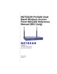
Mechanical Description
Connect the adapter to your Ethernet-enabled device
A. Combine the antenna with the product to wirelessly connect to the 802.11g networks.
B. Connect one end of an Ethernet cable to the product and connect the other end to the Ethernet
LAN port located on the device (e.g., a gaming console, laptop,desktop computer, or network
printer).
C. Connect the power adapter to product.
The following table provides an overview of each LED activity:
LED Definition
PWR
Activity
Description
Green
Power enabled
WLAN
Green
LAN
Green
Off: No Wireless LAN
traffic activity
On: Wireless LAN traffic
activity.
Off: No Ethernet traffic
activity
Flashing: Wired LAN
traffic activity
On: Connect to the
Ethernet.
Default
Press the “default” button for about 3 seconds until all LEDs go off. This action will restore to
the factory default settings of the 3-in-1 and enable you to configure the product via web again.
6
Besides, this is also used when you forget the password.
Hardware Installation
Take the following steps to set up your Access Point.
Site Selection
Before installation, determine the Access Point location. Proper placement of the Access Point is
critical to ensure optimum radio range and performance. You may use the Site Survey and
Access Points Browser utility (The utilities included with the wireless PC Card) to choose a
proper placement for your Access Point. Typically, the best location to place your Access Point
at your site is the center of your wireless coverage area. Try to place your mobile stations within
the line of sight. Obstructions may impede performance of the Access Point.
Access Point Placement
You can place the Access Point on a flat surface such as a table or cabinet, or mount the unit on a
vertical surface like a wall. The integrated antenna of your Access Point performs best in an open
environment with as few obstructions as possible. In most situations placing the Access Point as
pictured below will provide satisfactory performance results.
Connect the Ethernet Cable
The 54Mbps Wireless LAN Access Point supports 10/100M Ethernet connection.Attach your
UTP Ethernet cable to the RJ-45 connector on the Access Point. Then connect the other end of
the RJ-45 cable to a hub or a station.
Power On
Connect the power adapter to the power socket. Your Access Point then will automatically enter
the self-test phase. During the self-test, the LAN will flash. Finally,the PWR LED will light
permanently as the Access Point enters normal operation.
Initialize
Have initial value , network of bridge whether which is short of province parameter set up ,
is it install after finishing is it can make working to it to supply powering in hardware to need
only.
Warning:We cannot assume the responsibility for the damage from using with the
other power adapter supplier.
7
3. Configuring XG-580PLUS
¾ Using the Web Management
Using the Web Management
The built-in Web Management provides you with a user-friendly graphical user interface to
manage the AP. The AP with an assigned IP address (e.g. http://192.168.0.2) will allow you via
web browser (e.g. Netscape Navigator 3.0 ~ 4.5 or MS Internet Explorer 4.0) to monitor and
configure.
Run Web explorer.
Enter the IP address of the AP in the Address field. The default IP Address is 192.168.0.2.
You will have access to Web Pages of the AP.
Enter the password to login to the AP. The default password is default. The main page will
show up.
8
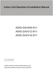
The AP main page contains four items.
¾ Information:
General: This item displays the general information of the AP such as the MAC
address and Firmware Version.
9
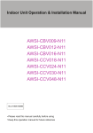
¾ Configuration:
General: You may make the settings on the AP such as Access Point Name, Radio
mode, ESSID, channel and password etc.
10
AP Name: In this field, you may enter any name. This will enable you to manage your AP more
easily if you have multiple Access Points on the network. Besides, Access Point Name can be
used to prevent you from forgetting an IP Address and fail to access the website. Try to type the
nickname you like to identify the website, then press the button of “Apply” to reboot. Whenever
you want to get back to the website again, just type the name you login.
Wireless Mode: Select the work mode.
AP Mode: The system can be configured to work as a wireless network access point. Note that
the AP acts only as a layer 2 bridge and does not act as a DHCP server. In other words, it does
not supply dynamic IP addresses and instead relies on the network to supply them.
Station Mode: When configuring as a station mode, the device is now acting as a wireless
client. The product will associate to an AP within its range in infrastructure mode, or join with
another 5-in-1 device in Client mode in an ad-hoc network.
AP with repeating: In this mode, you can extend the range of a wireless network. Wireless
clients can associate with the repeater to communicate with each client on your network. Note
that all the Access Points’ IP address must be set in the same network and make sure that Mode,
SSID, Channel and encryption settings are set the same for all of your AP with repeating(s).
Network Type: There are 2 network types for the wireless station adapter to operate. If you need
to access company network or Internet via Access Point, select “Infrastructure”. To set up a
group of wireless stations for files and printer sharing, select “Ad-Hoc” (without Access Point).
For Ad-Hoc operation, the same ESSID is required to set for the wireless stations.
11
ESSID: The ESSID is a unique ID used by Access Points and Stations to identify a wireless LAN.
Wireless clients associating to any Access Point must have the same ESSID. The default ESSID
is ANY. The ESSID can have up to 32 characters.
Channel: Select a clear and available channel as an operational channel for your wireless station
adapter when it performs as Ad-Hoc mode.
Mode: There are three different wireless modes to operate, “B Only Mode”, “G Only Mode”, and
“B/G Mixed Mode”. In B/G Mixed Mode, the wireless station adapter is compatible with a mix
of both 802.11g and 802.11b clients. You will see that the factory-set default “B/G Mixed Mod”
will prove the most efficient. B Only Mode is compatible with 802.11b clients only. This mode
can be used only if you do not allow any 802.11g clients to join a network. G Only Mode is
compatible with 802.11g clients only. This mode can be used only if you do not allow any
802.11b clients to access to the network. To switch the mode, select the desired mode form the
pull-down menu next to “Mode”.
Rate: The wireless station adapter provides various data rate options for you to choose. Data
rates options include Auto, 1, 2, 5.5, 11, 6, 9, 12, 18, 24, 36, 48 and 54. The default setting is
Auto.
Country/Region: Allows you to select country domain in case there is any chances that you
would use wireless network in other countries. There are a total of 11 countries for you to select.
They are Africa, Asia, Australia, Canada, Europe, France, Israel, Japan, Mexico, South America,
and USA. Note that if your AP and station adapter are in different standards, please use the
“Country/Region” item to switch the standards of the station adapter (For example, when set to
client mode, if your Access Point is America standard but your station adapter is Japanese
standard, you can pull down the “Country/Region” option to switch your station adapter from
Japanese standard to American standard.).
Password: You may change the default password by entering the new password.
Note:Click “Apply” if you have made any changes.
Security
WEB Mode: This wireless adapter allows you to create up to 4 data encryption keys to secure
your data from being eavesdropping by unauthorized wireless user. To enable the encryption, all
devices on the network must share the same WEP key.
Disable: Allows the wireless station adapter to communicate with the Access Point without any
data encryption.
WEP40: Requires the wireless station adapter to use data encryption with 40-bit algorithm when
communicating with the Access Point.
WEP128: Allows the wireless station adapter to communicate with the Access Point with data
128-bit encryption algorithm.
WPA-PSK: Allows the wireless station adapter to communicate with the Access Point with a
12
more secure data protection than the WEP. Here you can select the WPA with PSK mode to
improve the data security and privacy during wireless transmission. The present WPA supplied
with this adapter is used in a pre-shared key mode, which does not require an authentication
(Radius) server.
Access Control
When configuring the adapter with AP mode operation, the Access Control is a powerful security
feature that allows you to specify which wireless stations are allowed or denied in the list
including:
Open: Allows any wireless station to access the network.
Allow: Any wireless station in this list attempting to access the network is allowed.
Deny: Any wireless station in this list will be denied access.
To add the Mac address of each wireless station on your network by entering the Mac
address of the client you desire to add into the list. Click “Add”, and then “Apply” to
save the settings. To delete a Mac address from the list, select the Mac address you
want to delete by clicking “Del” and then “Apply” to save the settings.
13
Parameter Log
The Parameter log item allows you to save settings to the local hard drive by clicking“Save”.
When you click the “Browse” button, you can select the saved setting files.To click “Load”, the
saved settings will be loaded back.
14
Advanced
15
RTS Threshold:
Request to Send Threshold. The packet size that is used to determine if it should use the
CSMA/CD(Carrier Sense Multiple Access with Collision Detection)mechanism or the
CSMA/CA mechanism for packet transmission. With the CSMA/CD transmission mechanism,
the transmitting station sends out the actual packet as soon as it has waited for the silence period.
With the CSMA/CA transmission mechanism, the transmitting station sends out an RTS packet
to the receiving station, and waits for the receiving station to send back a CTS (Clear to Send)
packet before sending the actual packet data.
Default: 2346
Fragmentation Threshold:
This is the maximum packet size used for fragmentation. Packets larger than the size
programmed in this field will be fragmented. The Fragment Threshold value must be larger than
the RTS Threshold value.
Default: 2346
Beacon Interval:
The Beacon Interval. Specifies the interval time between 20ms and 1000ms for each beacon
transmission
Default: 100
DTIM:
16
The Delivery Traffic Indication Message. Specifies the data beacon rate between 1 and 255.
Default: 1
Preamble Type:
A long transmit preamble may provide a more reliable connection or slightly longer range. A
auto transmit preamble gives better performance.
Enable Protection:
The function protect link quality.
Enable Hidden AP:Enable the function ,The AP don’t broadcast the ESSID .
AnyIP(Unable in Bridge Mode):the terminal with any ip address can visit the network
¾ TCP/IP
General
You may assign a proper IP address to your wireless adapter manually. If you would like the
wireless adapter to obtain the IP address from the DHCP server on your network automatically,
enable the DHCP client function. Click the “Apply” button to make it effect.
17
¾ Statistics
General
This item will allow you to monitor the connection status when set to AP mode such as the
Mac Address, Link Status, Rate Type as well as RX/TX from Ethernet packets.
When set to Client mode, you may also open the General page to view the available Access
Points around your environment. The status includes Link Status, ESSID, BSSID, Channel and
Signal as well as RX/TX from Ethernet packets.
AP Browser
This AP Browser shows only when configuring your 3-in-1 as Station mode. By clicking the
“Refresh” button, the AP Browser will reload and display available Access Points around the
working environment. Besides showing the BSSID of each Access Point, it also displays ESSID,
Channel, Support Rate and Capability. To connect one of displayed Access Points, just select the
Access Point you desire and then click the “Connect” button to make the connection.
18
¾ Firmware Upgrade
Here, you can upload the latest firmware of the wireless adapter. You may either enter the file
name in the entry field or browse the file by clicking the “Browse” button. Then click the
“Apply” button to begin to upgrade the process.
19
4. Troubleshooting
¾
¾
FAQ
Technical support
FAQ
Technical support
If you meet difficulty and please contact our supplier in the course of installing and using
the AP.
20
Appendix
¾ Technical Specifications
¾ Glossary
¾ ASCII
Technical Specifications
Feature
Description
IEEE 802.11b/g WLAN Station Adapter
Host interface
One 10/100BaseT R-45 LAN port with Auto-MDIX
Antenna
One external dipole antenna
Data Rate
Power Consumption
11g Mode: 54, 48, 36, 24, 18, 12, 9, 6 Mbps
11b Mode: 11, 5.5, 2, 1 Mbps
11g: TX:650mA ; RX: 450mA (max)
11b: TX: 500mA ; RX: 450mA (max)
Voltage
DC 5V/2A
Support OS
Win98SE/ME/2000/XP
USA (FCC) 11 Channels: 2.412GHz~2.462GHz
Channels
Europe (ETSI) 13 Channels : 2.412GHz~2.472GHz
Japan (TELEC) 14 Channels : 2.412GHz~2.483GHz
RF output
Sensitivity
15dBm Typical
11g : 54Mbps OFDM<-65dBm
11b+: 22Mbps PBCC<-80dBm
11g Orthogonal Frequency Division Multiplexing (64QAM, 16QAM,
Modulation
QPSK, BPSK)
11b Direct Sequence Spread Spectrum (CCK, DQPSK, DBPSK)
Security
64/128-bit WEP Encryption
Dimension
80.90mm(L)*108.20mm(W)*29.80mm(H)
Weight
<75g
Environment
Operating
Temperature
Storage
Temperature
Humidity
0~55C
-20~70C
5~95%
21
Glossary
AP
The abbreviation of Access Point, refer in particular to the wireless access point.
BWA
The abbreviation of Broadband Wireless Access Point, does not have the network
bridge to refer in particular to broadband .
IEEE 802.11
Include IEEE 802.11a/b/g。
Notice
Show that there is important information that reminds you with better using the
equipment.
warning
It have potential dangerous operation will do harm to hardware of the equipment or
make data not to lose or make equipment not to can be used normally all to show.
SSID
It distribute to may make wireless users can connect to the network name of AP to
use for. It is different from the access point name of AP, it was used for
distinguishing AP that that is only available for AP.
AP IP address
If has not used DHCP server in the network , has needed to assign a legal IP address
for AP , used to land to AP through HTTP. IP address of acquiescence is http://192.
168. 0. 228.
HTTP
User’s name/password
Used for landing admin password or password of user name of acquiescence to AP
from WEB page.
Encrypt setting
Which kind of encryption ways are not needed to decide to set up for AP with you
according to the environment.
Link test
When AP is chosen as mode of bridge graft, this function can be used for
determining the connection state with an purpose MAC address.
MAC control
This function is only valid under AP mode, invalid under the mode of bridge graft.
Used in MAC address to filter.
22
ASCII
You can dispose sexadecimal number system counting or ACSII one yard of keys encrypted as WEP .
Sexadecimal number system is made up by 0-9 and A-F (letter does not distinguish capital and small letter );
ACSII yard is by 0-9 figures , A-F , a-f (letter distinguishes capital and small letter), and the punctuation mark
makes up . Each ACSII yard can is it say to count by one sexadecimal number system of two. One-one ASCII
yard of all and sexadecimal number system are counted to make forms and list all.
ASCII
Character
Hex
Equivalent
ASCII
Character
Hex
Equivalent
ASCII
Character
Hex
Equivalent
ASCII
Character
Hex
Equivalent
!
21
9
39
Q
51
i
69
"
22
:
3A
R
52
j
6A
#
23
;
3B
S
53
k
6B
$
24
<
3C
T
54
l
6C
%
25
=
3D
U
55
m
6D
&
26
>
3E
V
56
n
6E
‘
27
?
3F
W
57
o
6F
(
28
@
40
X
58
p
70
)
29
A
41
Y
59
q
71
*
2A
B
42
Z
5A
r
72
+
2B
C
43
[
5B
s
73
,
2C
D
44
\
5C
t
74
-
2D
E
45
]
5D
u
75
.
2E
F
46
^
5E
v
76
/
2F
G
47
_
5F
w
77
0
30
H
48
`
60
x
78
1
31
I
49
a
61
y
79
2
32
J
4A
b
62
z
7A
3
33
K
4B
c
63
{
7B
4
34
L
4C
d
64
|
7C
5
35
M
4D
e
65
}
7D
6
36
N
4E
f
66
~
7E
7
37
O
4F
g
67
8
38
P
50
h
68
23