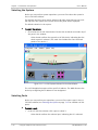
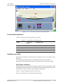
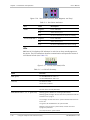
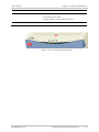
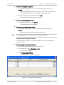
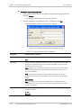
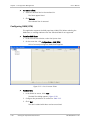
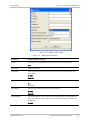
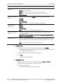
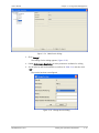
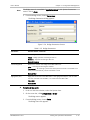
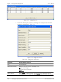
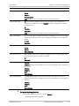
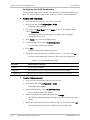
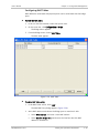
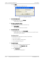
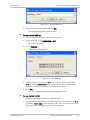
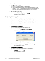
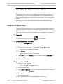
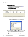
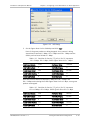
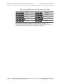
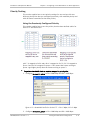
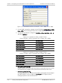
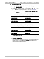
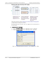
1
RADview-EMS/NGN Element Management System for NGN Applications LA-210 © 1994–2008 RAD Data Communications Publication 07/08 Contents Chapter 1. Introduction 1.1 1.2 Overview of LA-210 ................................................................................................... 1-1 RV-EMS/NGN LA-210 Overview ................................................................................... 1-2 Overview of the RADview FCAPS Model ................................................................... 1-2 System Level Operations ......................................................................................... 1-3 Chapter 2. Installation and Operation 2.1 2.2 2.3 2.4 2.5 Network Management Options ................................................................................... 2-2 Pre-configuring LA-210 for Network Management ...................................................... 2-2 Connecting a Terminal to the Control Port ............................................................... 2-3 Configuring the Host Parameters ............................................................................ 2-3 Configuring the Management Access ....................................................................... 2-4 Adding a Network Management Station (NMS) ........................................................ 2-4 Configuring the SNMP Communities......................................................................... 2-6 Connecting LA-210 to Network Management Stations ................................................ 2-7 Inband Management ............................................................................................... 2-7 Out-of-Band Management ...................................................................................... 2-7 Launching RV-EMS/NGN LA-210 .................................................................................. 2-8 Using the Graphical User Interface (GUI) ..................................................................... 2-9 LA-210 View Window .............................................................................................. 2-9 Title Bar ............................................................................................................. 2-9 Menu Bar ........................................................................................................... 2-9 Toolbar ............................................................................................................ 2-10 Status Bar ........................................................................................................ 2-10 LA-210 System ..................................................................................................... 2-11 RADview LA-210 Menu Maps ................................................................................. 2-12 Selecting the System ............................................................................................ 2-14 Selecting Ports...................................................................................................... 2-14 Front Panel Connectors ......................................................................................... 2-15 Indicators and LEDs .............................................................................................. 2-15 Port Status Indicators ....................................................................................... 2-15 LEDs ................................................................................................................ 2-16 Chapter 3. Configuration Management 3.1 3.2 Setting the System Parameters .................................................................................. 3-2 Viewing and Specifying Device Information .............................................................. 3-2 Setting System Date and Time ................................................................................ 3-4 Setting the Operational Parameters............................................................................ 3-6 Viewing and Configuring SHDSL Port Parameters ..................................................... 3-6 Viewing and Configuring Ethernet Port Parameters .................................................. 3-9 Configuring System Parameters............................................................................. 3-11 Configuring SHDSL Lines ....................................................................................... 3-11 Configuring the Flows ........................................................................................... 3-14 Configuring the Quality of Service..................................................................... 3-14 Adding, Editing and Removing Flows ................................................................. 3-23 Configuring OAM (CFM) ......................................................................................... 3-30 RV-EMS/NGN LA-210 i Table of Contents 3.3 User’s Manual Configuring Bridge Parameters .............................................................................. 3-34 Configuring the VLAN Membership .................................................................... 3-38 Configuring MAC Tables .................................................................................... 3-39 Configuring QoS ............................................................................................... 3-40 Configuring Fault Propagation ............................................................................... 3-42 Additional Tasks ....................................................................................................... 3-43 Resetting the Agent .............................................................................................. 3-43 Resetting the Configuration .................................................................................. 3-43 Chapter 4. Configuring a Flow-Based Point-To-Point Application 4.1 4.2 4.3 4.4 4.5 4.6 4.7 Configuring the ETX-202 and LA-210 Units ................................................................. 4-2 Configuration Sequence ............................................................................................. 4-2 Configuring the System Parameters ............................................................................ 4-4 Configuring Host IP Parameters ............................................................................... 4-4 Configuring ETX-202 Server and Client .................................................................... 4-4 Configuring ETX-202 Server ................................................................................ 4-5 Configuring ETX-202 Client ................................................................................. 4-6 Connecting LA-210 to the Management Station ......................................................... 4-8 Adding LA-210 to the Management Console ............................................................ 4-8 Launching the LA-210 View Window........................................................................ 4-8 Configuring LA-210 .................................................................................................... 4-9 Configuring LA-210 for Advanced Configuration .................................................... 4-13 Configuring the DSLAM ......................................................................................... 4-21 Using the Setup to Screen a Movie ........................................................................... 4-22 Using the VLC Media Player ................................................................................... 4-22 Testing the Flow Based Configuration....................................................................... 4-23 Ping Tests ............................................................................................................. 4-23 Policer Testing ...................................................................................................... 4-24 Priority Testing ..................................................................................................... 4-31 Using the Previously Configured Priority............................................................ 4-31 Defining the Same Priority to All Frames ........................................................... 4-34 Chapter 5. Performance Management 5.1 5.2 5.3 ii Viewing System Statistics ........................................................................................... 5-2 Polling the Agent .................................................................................................... 5-2 Setting the Polling Interval.................................................................................. 5-2 Viewing Flow Statistics ............................................................................................ 5-3 Viewing Service Statistics ................................................................................... 5-7 Clearing All Statistics ............................................................................................. 5-11 Viewing SHDSL Port Statistics ................................................................................... 5-11 Viewing Line Statistics........................................................................................... 5-11 Viewing PCS Statistics ........................................................................................... 5-14 Viewing ATM Statistics .......................................................................................... 5-14 Viewing VCC Statistics ........................................................................................... 5-16 Viewing Ethernet Port Statistics................................................................................ 5-17 Viewing Rx Frame Types ........................................................................................ 5-17 Viewing Tx Frame Types ........................................................................................ 5-18 Viewing Errors....................................................................................................... 5-19 Clearing All Statistics ............................................................................................. 5-21 RV-EMS/NGN LA-210 User’s Manual 5.4 Table of Contents Viewing OAM (CFM) Statistics ................................................................................... 5-21 Accessing the OAM (CFM) Statistics Dialog ............................................................ 5-21 Viewing Running Counters..................................................................................... 5-22 Viewing Current Frames ........................................................................................ 5-23 Viewing Current Delays ......................................................................................... 5-24 Viewing Interval Frames ........................................................................................ 5-25 Viewing Interval Delays ......................................................................................... 5-26 Chapter 6. Security Management 6.1 6.2 6.3 6.4 Understanding RADview User Security Levels .............................................................. 6-1 Monitor .................................................................................................................. 6-2 Technician .............................................................................................................. 6-3 Operator ................................................................................................................ 6-3 Administrator ......................................................................................................... 6-3 Configuring Host Parameters ...................................................................................... 6-3 Configuring SNMP ...................................................................................................... 6-4 Configuring Management Access ................................................................................ 6-6 Chapter 7. Fault Management 7.1 7.2 Managing the Event Reporting for OAM (CFM) ............................................................ 7-1 Managing the History Log........................................................................................... 7-6 Viewing the History Log .......................................................................................... 7-6 Clearing the History Log .......................................................................................... 7-9 RV-EMS/NGN LA-210 iii Table of Contents iv User’s Manual RV-EMS/NGN LA-210 Chapter 1 Introduction This chapter provides an overview for managing LA-210 using the RADviewEMS/NGN LA-210 management solution. It introduces the graphical user interface. It is assumed that you are familiar with basic RADview-EMS/NGN operations. For more information about basic RADview-EMS/NGN operations, refer to the RADview-EMS/NGN (PC) or (UNIX) User's Manual. This chapter contains the following topics: • Overview of LA-210 • RV-EMS/NGN LA-210 Overview Overview of the RADview FCAPS Model System Level Operations. 1.1 Overview of LA-210 RV-EMS/NGN LA-210 is an advanced DSL Ethernet access device operating at rates of up to 22 Mbps using G.SHDSL.bis EFM bonding technology (TC-PAM 16 or TC-PAM 32 line coding technologies) to transmit data rates of up to 5.7 Mbps over each copper pair with EFM bonding (2-wire line). RV-EMS/NGN LA-210 supports multiple data rates and works in full duplex mode over 2-wire, 4-wire, or 8-wire lines. In addition to the EFM mode, RV-EMS/NGN LA-210 operates the SHDSL link in ATM mode to be compatible with the existing DSLAM infrastructure. EFM bonding ensures that a failure or addition of a link does not drop the traffic being transmitted over the other wires in the group, nor is the capacity of the group decreased when a new link is added at lower rate. This is particularly relevant for operators offering Ethernet services in the First Mile where fiber is absent or impractical to install. RV-EMS/NGN LA-210 implements the IEEE.1Q standards to provide VLAN-tagging with four levels of prioritization, enabling carriers to offer differentiated Ethernet services. VLAN tagging can also be employed to separate traffic, ensuring transparency of the customer traffic and bolstering security of management traffic. RV-EMS/NGN LA-210 provides monitoring, control, and diagnostics of local and remote units via a terminal supervisory port. RV-EMS/NGN LA-210 Overview of LA-210 1-1 Chapter 1 Introduction User’s Manual 1.2 RV-EMS/NGN LA-210 Overview This chapter explains the steps required to get the RADview-EMS/NGN LA-210 management system for LA-210 version 1.5 up and running. It describes the graphical user interface, configurations, security and fault management. Specific tasks possible with RADview-EMS/NGN LA-210 are dealt with in the subsequent chapters in this manual. All the configurations and management support in this manual are tasks that can be performed with RADview. The RADview-EMS/NGN management system for LA-210 provides you with all the tools necessary to monitor the performance and configure the device parameters for its local and remote devices. The RADview-EMS/NGN management system for LA-210 units is accessed in two levels: • System Level • Port Level: SHDSL 10/100BASE-T Overview of the RADview FCAPS Model RADview provides a complete management solution for monitoring and controlling the RV-EMS/NGN LA-210 system. The RADview solutions conform to ITU-T Telecommunication Management Network (TMN) recommendations for SNMP management systems, known as the FCAPS model: 1-2 • Fault management – detects and correlates fault in network devices, isolates faults, and initiates recovery actions. • Configuration management – tracks configuration changes, and configures, installs, and distributes software and configuration files across the network. • Accounting management – collects accounting data and generates network usage reports. • Performance management – continuously monitors network performance (QoS, CoS) and resource allocation. • Security management – controls and restricts access to network resources. RV-EMS/NGN LA-210 Overview RV-EMS/NGN LA-210 User’s Manual Chapter 1 Introduction System Level Operations Table 1-1 lists the management tasks that are available when you select the entire system. Table 1-1. Mapping of FCAPS Functions to RADview-EMS/NGN LA-210 Menu Paths and Sections in this Manual FCAPS Component Function Device Level Path in RVEMS/NGN LA210 Port Level Section in this Manual Path in RVEMS/NGN LA210 Section in this Manual Fault > History Log Fault Management Clearing the system log buffer Fault > Clear History Log Clearing Alarms in the Alarm Buffer - Chapter 7 Configuration Management Viewing and configuring system information Configuration > System Info Configuring System Information - Chapter 3 Setting system date and time Configuration > Date & Time Setting System Date and Time - Chapter 3 Configuring fault propagation Configuration > Fault Propagation Configuring Fault Propagation - Chapter 3 Configuring flow settings Configuration > Flows Configuring Flow Settings - Chapter 3 Configuration > Bridge > Parameters Configuring Bridge Settings - Chapter 3 Configuration > Bridge > Ports Configuring Bridge Settings - Chapter 3 Configuration > Bridge > VLAN Membership Configuring Bridge Settings - Chapter 3 (Bridge mode) Configuring bridge settings (Bridge mode) RV-EMS/NGN LA-210 RV-EMS/NGN LA-210 Overview 1-3 Chapter 1 Introduction FCAPS Component Function Device Level Port Level Path in RVEMS/NGN LA210 Section in this Manual Configuration > Bridge > MAC Table Configuring Bridge Settings - Chapter 3 Configuration > QoS > Classification Configuring Quality of Service (QoS) - Chapter 3 Configuration > QoS > Mapping Configuring Quality of Service (QoS) - Chapter 3 Configuration > QoS > Ingress BW Profiles Configuring Quality of Service (QoS) - Chapter 3 Configuration > QoS > Rate Limitation Configuring Quality of Service (QoS) - Chapter 3 Configuration > QoS > CoS Profiles Configuring Quality of Service (QoS) - Chapter 3 Configuration > QoS > Marking Profiles Configuring Quality of Service (QoS) - Chapter 3 Configuration > QoS > Internal Queue Profiles Configuring Quality of Service (QoS) - Chapter 3 Resetting the system hardware Configuration > Reset > HW Resetting the System Hardware - Chapter 3 Resetting system configurations Configuration > Reset > Config Resetting System Configuration - Chapter 3 Configuring QoS parameters (Bridge mode) Configuring QoS parameters (Flow mode) 1-4 User’s Manual RV-EMS/NGN LA-210 Overview Path in RVEMS/NGN LA210 Section in this Manual RV-EMS/NGN LA-210 User’s Manual FCAPS Component Chapter 1 Introduction Function Polling the Agent Device Level Port Level Path in RVEMS/NGN LA210 Section in this Manual Configuration > Poll Agent Polling the Agent Configuration - Chapter 3 Viewing and configuring Ethernet port parameters Performance Management Setting the polling interval for updating statistics in dialog boxes Statistics > Polling Interval Viewing and modifying the Host parameters Options > Host Section in this Manual Configuration > Parameters Viewing and Configuring Ethernet Port Parameters - Chapter 3 Statistics > Rx Frame Types Port Statistics - Chapter 5 Statistics > Tx Frame Types Port Statistics - Chapter 5 Statistics > Errors Port Statistics - Chapter 5 Statistics > Clear Statistics Port Statistics - Chapter 5 Setting the Polling Interval - Chapter 5 Viewing port statistics Security Management Path in RVEMS/NGN LA210 Configuring Host Parameters - Chapter 6 Configuring SNMP Options > Manager List Configuring SNMP - Chapter 6 Configuring Management Access Options > Access Configuring Management Access - Chapter 6 RV-EMS/NGN LA-210 RV-EMS/NGN LA-210 Overview 1-5 Chapter 1 Introduction 1-6 RV-EMS/NGN LA-210 Overview User’s Manual RV-EMS/NGN LA-210 Chapter 2 Installation and Operation This chapter explains the installation and operation required to get the RADviewEMS/NGN system for LA-210 up and running. It also describes the RADviewEMS/NGN LA-210 graphic user interface (GUI) and how to select the system and its ports. This chapter explains how to perform the following tasks: • Network Management Options • Pre-configuring LA-210 for Network Management • Connecting a Terminal to the Control Port Configuring the Host Parameters Configuring the Management Access Adding a Network Management Station (NMS) Configuring the SNMP Communities Connecting LA-210 to Network Management Stations Inband Management Out-of-Band Management • Launching RV-EMS/NGN LA-210 • Using the Graphical User Interface (GUI) RV-EMS/NGN LA-210 LA-210 View Window Title Bar Menu Bar Toolbar Status Bar LA-210 System RADview LA-210 Menu Maps Selecting the System Selecting Ports Front Panel Connectors Indicators and LEDs Port Status Indicators LEDs. Network Management Options 2-1 Chapter 2 Installation and Operation 2.1 User’s Manual Network Management Options LA-210 units have a local management subsystem that controls the operation of all of its circuits. The subsystem supports various management interfaces, including inband and out-of-band SNMP management (for example, RADview), Telnet, and local management via an ASCII terminal or a Web browser. RADview management software is typically used to support large networks. Some parameters, such as the Operation Mode, CANNOT be changed from within RADview, since they are read only parameters. However, you can use the built-in management menu-driven interface of the LA-210 to configure the operational mode. The configuration menus are accessible from a serial connection to the device control port or using the Telnet protocol via a connection to the Ethernet LAN port. For complete information about managing LA-210 using the terminal, see the LA-210 Installation and Operation Manual. Note • Changing the Operation Mode erases some parameters, such as the Ethernet host IP, and disconnects any remote management sessions. • Changing the Ethernet host IP address disconnects any remote management sessions. For RADview management, you would have to add the new managed element (host) IP address to the EMS or SNMPc map. RADview management software is used for managing large networks. RADview uses SNMP messages to manage LA-210 can be managed by a network management station (NMS) via one of the unit’s Ethernet ports. The connection can be made either from a local LAN, or from a remote location, via a PSN connected to one of the ETX Ethernet ports. 2.2 Pre-configuring LA-210 for Network Management LA-210 can be managed by a network management station which is located on the LAN connected to the one of the unit’s Ethernet ports. To remotely administer LA-210 via a Network Management Station (NMS), it is necessary to first configure the basic LA-210 parameters via an ASCII terminal command line interface (CLI) session to the LA-210 Control Port. The following steps are required: 2-2 • Connecting a terminal to the control port • Configuring the host parameters • Entering device information • Configuring LA-210 communities • Configuring the host encapsulation • Configuring the network managers • Controlling management access • Configuring control port parameters. Pre-configuring LA-210 for Network Management RV-EMS/NGN LA-210 User’s Manual Chapter 2 Installation and Operation Connecting a Terminal to the Control Port In order to configure the basic IP parameters, it is necessary to connect an ASCII terminal to the LA-210 control port and log in. ³ To configure the LA-210 system parameters: 1. Configure an ASCII terminal as follows: Bits per second: 115,200 Data bits: 8 Parity: None Stop bits: 1 Flow control: None. VT100 emulation. 2. Connect the terminal to the LA-210 CONTROL port. 3. Press <Enter> several times (to allow LA-210 to detect the rate). 4. Initiate the control session by entering the Administrator user name and password. Configuring the Host Parameters LA-210 allows entering IP parameters manually or using parameters acquired from the DHCP server. ³ To configure the Host parameters: 1. Display the Host menu (Configuration > System > Management > Host). 2. Select IP Address to define the host IP address. 3. Select IP Mask to define the host IP mask. 4. Select Default Gateway to set the default gateway IP address. 5. Select Default IP to enter a default IP address. Configuring a default IP address is necessary if you want to preserve a Telnet or HTTP connection to LA-210 after having disabled its DHCP client. Note The default gateway must be in the same subnet as the host. RV-EMS/NGN LA-210 Pre-configuring LA-210 for Network Management 2-3 Chapter 2 Installation and Operation User’s Manual LA-210 Configuration>System>Management>Host 1. 2. 3. 4. 5. 6. 7. IP Address Mask Default Gateway Read Community Write Community Trap Community Encapsulation (0.0.0.0) (255.255.255.0) (0.0.0.0) (public) (private) (public) > > ESC-prev.menu; !-main menu; &-exit 1 Mngr/s Figure 2-1. Host Menu (LA-210) Configuring the Management Access LA-210 allows you to enable access to the management system via an SNMP application. ³ To configure the Management Access: • Display the Management Access menu (Configuration > System > Management > Management Access), and set SNMP Access to Enable. LA-210 Configuration>System>Management>Management Access 1. 2. 3. 4. 5. 6. User Access RADIUS Parameters TELNET/SSH access SNMP Access WEB Access Access Policy > > > > > > (Enable) (Enable) (Enable) (Enable Remote) > ESC-prev.menu; !-main menu; &-exit 1 Mngr/s Figure 2-2. Management Access Menu (LA-210) Adding a Network Management Station (NMS) In order to remotely configure LA-210, the NMS needs to be listed in the Manager List. NMS configuration defines the IP address of a new network management station (NMS), and the enterprise-specific traps that will be sent to the new network management station. The maximum number of network management stations is 10. If this number is exceeded, you must delete an existing station. Each NMS is automatically assigned an index number in the range of 1 to 10. 2-4 Pre-configuring LA-210 for Network Management RV-EMS/NGN LA-210 User’s Manual Chapter 2 Installation and Operation When you allow sending general and alarm traps to a network manager, you can mask or unmask each trap (general or interface-specific). See the following section. To add a network management station: ³ 1. From the Management menu (Configuration > System > Management), select Managers List. The Managers List menu appears (see Figure 2-3). 2. In the Managers list, select the IP address, which is 0.0.0.0 by default, and then select Change Cell. The Manager is assigned. 3. To mask or unmask a manager, select the desired manager’s Manager Trap Mask entry and select Change Cell. LA-210 Configuration>System>Management>Managers List Manager ID 1. Manager IP 0.0.0.0 Manager Trap Mask Mask 2. 0.0.0.0 Unmask 3. 0.0.0.0 Unmask 4. 0.0.0.0 Unmask 5. 0.0.0.0 Unmask 6. 0.0.0.0 Unmask 7. 0.0.0.0 Unmask 8. 0.0.0.0 Unmask 9. 0.0.0.0 Unmask 10. 0.0.0.0 Unmask 1. Change Cell A – add R – remove X – clear table ESC-prev.menu; !-main menu; &-exit; ?-help Figure 2-3. Manager List Menu (LA-210) RV-EMS/NGN LA-210 Pre-configuring LA-210 for Network Management 2-5 Chapter 2 Installation and Operation User’s Manual Configuring the SNMP Communities LA-210 allows you to specify the communities under which the ETX management agent accepts SNMP command. ³ To configure the authentication community: 1. Display the Host (Management) menu (Configuration >System >Management >Host), and configure the following parameters: 2. Configure the desired parameters: Read Community to enter the name of a community with read-only authorization. Write Community to enter the name of a community with write authorization. Trap Community to enter the name of a community to which LA-210 sends traps. 3. Type S to save the changes. Note The community names are case sensitive. LA-210 Configuration>System>Management>Host 1. 1. 2. 3. 4. 5. 6. IP Address Mask Default Gateway Read Community Write Community Trap Community Encapsulation (0.0.0.0) (255.255.255.0) (0.0.0.0) (public) (private) (public) > > ESC-prev.menu; !-main menu; &-exit 1 Mngr/s Figure 2-4. Host Menu (LA-210) 2-6 Pre-configuring LA-210 for Network Management RV-EMS/NGN LA-210 User’s Manual Chapter 2 Installation and Operation 2.3 Connecting LA-210 to Network Management Stations LA-210 can be managed by a network management station (NMS) via of the unit Ethernet ports. The connection can be made either from a local LAN, or from a remote location, via a PSN connected to one of the ETX Ethernet ports. Inband Management RV-EMS/NGN LA-210 can be managed via SNMP by a Network Management Station (NMS) over one of unit’s SHDSL uplink ports. ³ To connect LA-210 to the Network Management Station: 1. Verify that the management parameters are properly configured. 2. Connect an Ethernet ports to the PSN on which management traffic from an authorized NMS flows. Out-of-Band Management RV-EMS/NGN LA-210 can be managed via SNMP by a Network Management Station (NMS) on the LAN (hub or switch) connected to the one of the unit’s Ethernet ports. ³ To connect LA-210 to the Network Management Station: 1. Connect one of the Ethernet links to a port of an Ethernet switch or hub serving the network to which the NMS is connected. 2. Make sure that the physical port connected to the NMS network is not bound to a bridge. RV-EMS/NGN LA-210 Connecting LA-210 to Network Management Stations 2-7 Chapter 2 Installation and Operation 2.4 User’s Manual Launching RV-EMS/NGN LA-210 Begin using RADview-EMS/NGN LA-210 by launching the respective LA-210 View window. ³ To launch the LA-210 View window: • On the map, select and double-click the LA-210 icon. The respective LA-210 View window opens. You can now perform configuration and monitoring functions in the entire LA-210 system. Figure 2-5. SNMPc Management Console 2-8 Launching RV-EMS/NGN LA-210 RV-EMS/NGN LA-210 User’s Manual Chapter 2 Installation and Operation 2.5 Using the Graphical User Interface (GUI) From the LA-210 View window, you can configure and monitor all the LA-210 system elements.) LA-210 View Window The RADview-EMS/NGN LA-210 View window displays a dynamic graphical representation of the LA-210 front and back panels. The view varies per LA-210 and per number of ports in the device: • Title bar • Main menu bar • Toolbar • LA-210 device (front and back panel views): • Front panel: includes several LEDs indicating statuses of power, Ethernet links, and alarms Back panel: includes AC/DC power connector, network and user Ethernet ports, and V.24 terminal connector Status bar. Title Bar Figure 2-6. Title Bar The title bar (at the top of the View window) displays the name or IP address of the element given on the Network station (SNMPc or HPOV) and whether the device is connected or disconnected. Menu Bar Figure 2-7. Main Menu Bar The main menu bar has drop-down sub-menus. Click a menu to display all the items in that menu. The menu items allow you to perform operations related to the selected elements in the LA-210 system. The menus are context sensitive; menu items are enabled or disabled as applicable to the selected element. In addition to using the menu bar, operations related to specific elements can also be performed using pop-up menus activated by right-clicking the mouse over the selected element. RV-EMS/NGN LA-210 Using the Graphical User Interface (GUI) 2-9 Chapter 2 Installation and Operation User’s Manual Toolbar System Level Port Level Figure 2-8. Toolbars Below the menu bar appears toolbar icons that allow you to perform specific LA210 operations related to the selected elements in the LA-210 system with a single mouse-click. This toolbar is context sensitive; the icons displayed change depending on the LA-210 element currently selected. Table 2-1. Toolbar Buttons Icon Name Function System Info Displays system info Poll Agent Poll system User’s Manual Displays online help file of user’s manaual Status Bar Figure 2-9. LA-210 Status Bar The LA-210 status bar appears at the bottom of the View window and indicates the current state of the system, as summarized in Table 2-2. Table 2-2. Status Types and Descriptions 2-10 Status Description Working Connection to the device is in progress Waiting Waiting for connection to the device Interrupted Connection to the device failed (time-out) Ready Connection to the device is successful Polling Device polling is in progress. Using the Graphical User Interface (GUI) RV-EMS/NGN LA-210 User’s Manual Chapter 2 Installation and Operation LA-210 System The main, central workspace of the View window is a dynamic graphical representation of the front and back panels of the LA-210 device. In this workspace you can select the system or the network or user ports to invoke specific menu commands to perform activities, such as configuration and fault management. Note that you can right-click the mouse over selected elements to invoke the relevant menu commands. When you perform certain activities, such as clicking the System Information button, a dialog box is displayed (in a secondary window) on top of the LA-210 View window. Figure 2-10. LA-210 System RV-EMS/NGN LA-210 Using the Graphical User Interface (GUI) 2-11 Chapter 2 Installation and Operation User’s Manual RADview LA-210 Menu Maps Configuration Fault Event Report Configuration for OAM (CFM) Services System Info Date and Time System Parameters History Log SHDSL Lines Statistics Options Help Polling Interval Host User’s Manual Flows Statistics Manager List About LA-210 OAM (CFM) Access Clear History Log Bridge Clear All Statistics Parameters Ports VLAN Membership MAC Table Flows QoS Classification Mapping OAM (CFM) Fault Propagation Reset HW Configuration Poll Agent Exit Figure 2-11. System Level Menu Map Note • Some parameters are unavailable, depending on whether the unit operates in Flow mode or Bridge mode. • These menus are also available as shortcut menus upon right-click anywhere in the system view. 2-12 Using the Graphical User Interface (GUI) RV-EMS/NGN LA-210 User’s Manual Chapter 2 Installation and Operation Figure 2-12. Port Level Menu Map – Ethernet Ports Configuration Fault Statistics Options Help Line Status Line User’s Manual Parameters PCS About LA-210 Logical Layer Parameters ATM VCC Clear Statistics Figure 2-13. Port Level Menu Map – Ethernet Ports Note • Some parameters are unavailable, depending on whether the unit operates in Flow mode or Bridge mode. • These menus are also available as shortcut menus upon right-click anywhere in the system view. RV-EMS/NGN LA-210 Using the Graphical User Interface (GUI) 2-13 Chapter 2 Installation and Operation User’s Manual Selecting the System Before you can perform system operations, you must first select the system in the LA-210 View window. The network and user ports may be selected. All other areas that are not ports will represent the system and a frame around the panel will be displayed. The default selection is the system. ³ To select the system: • Click inside the LA-210 View window. Ensure that no border surrounds any of the ports in the window. A blue border outlines the respective LA-210 device, indicating that the whole system is selected. (The main view includes the front and back panels of the device.) Figure 2-14. LA-210 System Selected in the View Window The LA-210 application opens with a specific IP address. The NMS discovers the device by recognizing the IP address it was designated. Selecting Ports Before you can perform port operations, you must first select a port in the LA210 View window (see Selecting the System on page 2-12 for available LA-210 ports). ³ To select a port: • In the LA-210 View window, click a port to select it. A blue border outlines the selected port, indicating that it is selected. 2-14 Using the Graphical User Interface (GUI) RV-EMS/NGN LA-210 User’s Manual Chapter 2 Installation and Operation Figure 2-15. LA-210 Port Selected in the View Window Front Panel Connectors Table 2-3 lists the ports and connectors of LA-210. Table 2-3. LA-210 Ports and Connectors Name Number of Ports Connector Type Control 1 DB9 SHDSL 1 or 2 RJ-45 10/100/1000BASE-T 1–4 RJ-45 Indicators and LEDs This section provides lists and color/status descriptions of the LA-210 device LED indicators. The LA-210 View window uses the standard RAD color codes to indicate operational and communication status of the agent, ports, and power supply. Port Status Indicators Operational status for ports will be indicated by color within the port itself, based on polling and trap notifications of interfaces administrational/operational status. The port status is color-coded in gray, magenta, or light blue. Table 2-4 lists and describes the port status colors. There is no indication for the Control and Alarm ports. RV-EMS/NGN LA-210 Using the Graphical User Interface (GUI) 2-15 Chapter 2 Installation and Operation User’s Manual Figure 2-16. Port Status Indicators (Blue, Magenta, and Gray) Table 2-4. Port Status Indicators Port Color Description SHDSL Magenta Errors indicated Blue Active test on port Gray No errors exist and no tests are running Magenta Errors indicated Blue Active test on port Gray No errors indicated and no tests running 10/100/1000 BASE-T LEDs RADview LA-210 displays LED indicators in real-time as they actually appear on the device. The LED indications describe communication and operation status of LA-210 and its links (see Table 2-5). Figure 2-17. LA-210 (Front Panel) LEDs Table 2-5. LA-210 LED Summary Name Function PWR (green) On: RV-EMS/NGN LA-210 is on Off: RV-EMS/NGN LA-210 is off TST (red) On: A test is active Off: A test is inactive ALM (red) On: A new alarm is detected in the alarm buffer Off: No alarm currently detected WAN (SHDSL SYNC 1, 2, 3, 4 - green/red) Blinking (green): SHDSL line is being synchronized Blinking (green/orange): At least one line synchronized and the second one is trying to. On (orange): At least one line is synchronized and at least one line is not. On (green): All enabled lines are synchronized Blinking (red): No line is synchronized, at least one line is trying to synchronize. On (red): No line is synchronized. 2-16 Using the Graphical User Interface (GUI) RV-EMS/NGN LA-210 User’s Manual Chapter 2 Installation and Operation Name Function ETH (LINK/ACT – green/yellow) On (green): Ethernet link is up Off: Ethernet link is down Blinking (yellow): Data is being transferred E1 Off: Not used Figure 2-18. LA-210 (Front Panel) LEDs RV-EMS/NGN LA-210 Using the Graphical User Interface (GUI) 2-17 Chapter 2 Installation and Operation 2-18 Using the Graphical User Interface (GUI) User’s Manual RV-EMS/NGN LA-210 Chapter 3 Configuration Management This chapter discusses how to configure the LA-210 management system using RADview-EMS/NGN. This chapter describes how to configure LA-210, and explains how to perform the following tasks: • Configuration Management • RV-EMS/NGN LA-210 Viewing and Specifying Device Information Setting System Date and Time Setting the Operational Parameters Viewing and Configuring SHDSL Port Parameters Viewing and Configuring Ethernet Port Parameters Configuring System Parameters Configuring SHDSL Lines Configuring the Flows Configuring the Quality of Service Adding, Editing and Removing Flows Configuring OAM (CFM) Configuring Bridge Parameters • Setting the System Parameters Configuring the VLAN Membership Configuring MAC Tables Configuring QoS Configuring Fault Propagation Additional Tasks Resetting the Agent Resetting the Configuration Setting the System Parameters 3-1 Chapter 3 Configuration Management 3.1 User’s Manual Setting the System Parameters RADview allows you to view and modify LA-210 configuration. The Configuration menu provides access to system level configuration. Figure 3-1. System Level Configuration Menu The System Info command enables you to view and set physical information about LA-210. Viewing and Specifying Device Information ³ To view and specify LA-210 device information: 1. In the LA-210 View window, select the system. 3-2 Setting the System Parameters RV-EMS/NGN LA-210 User’s Manual Chapter 3 Configuration Management 2. On the menu bar, click Configuration > System Info. Figure 3-2. System Information Dialog Box 3. Fill in the fields, as described in Table 3-1. 4. Click <Set> to implement the changes. Table 3-1. System Information Dialog Box Parameters Parameter Possible Values / Remarks Description Description of the device, including the full name and version identification of the device’s hardware type and software operating-system. Read-Only Object ID System identification number Read-Only Name System name Format: String (32 characters) Contact Name of the contact person for this system Format: String (32 characters) Location Physical location of the device Format: String (32 characters) System Up Time Length of time the system has been running. Format: d: days, hh:mm:ss Read-Only Number of Interfaces Number of network interfaces present in the system. Read-Only RV-EMS/NGN LA-210 Setting the System Parameters 3-3 Chapter 3 Configuration Management Note User’s Manual The System Information Name, Contact, and Location dialog box fields are enabled, regardless of whether or not there is communication with the agent. Setting System Date and Time RADview allows you to set the date and time for the LA-210 internal real-time clock. In addition, you can configure an SNTP server, to lock LA-210 to a reliable clock source. . ³ To set system date and time: 1. In the LA-210 View window, select the system. 2. On the menu bar, click Configuration > Date and Time. Figure 3-3. Date & Time Dialog Box 3. Fill in the fields, as described in Table 3-2. 4. To change the date, in the Date field, do one of the following: Type a date OR Click the Date combo box drop-down arrow to display a calendar from which you can select the date by clicking the relevant option. 5. Click <Apply> to implement the changes. 3-4 Setting the System Parameters RV-EMS/NGN LA-210 User’s Manual Chapter 3 Configuration Management Table 3-2. Date & Time Dialog Box Parameters Parameter Possible Values / Remarks Date System date. Format: yyyy-mm-dd Note: Can be set when Mode is Unicast Client. Time System time. Format: hh:mm:ss Note: Can be set when Mode is Unicast Client. SNTP Mode SNTP mode. Disable Unicast Client Time Zone SNTP time zone. GMT–12:00 GMT–11:00 … GMT–1:00 GMT GMT+1:00 … GMT+12:00 Note: Server IP Address • Disabled when Mode is Disable. • Enabled when Mode is Unicast Client. IP address of the SNTP server. Note: Update Interval (min) • Disabled when Mode is Disable. • Enabled when Mode is Unicast Client. SNTP update interval in minutes. Period of time after which LA-210 polls the SNTP server. 1…1440 Note: RV-EMS/NGN LA-210 • Disabled when Mode is Disable. • Enabled when Mode is Unicast Client.. Setting the System Parameters 3-5 Chapter 3 Configuration Management 3.2 User’s Manual Setting the Operational Parameters This section discusses how to manage LA-210 ports for operation using RADview LA-210. Managing ports includes the following tasks: • Selecting the port • Viewing and modifying port parameters Additional port operations are discussed in the following chapters: • Monitoring port performance (see Chapter 5) • Configuring event reports for Ethernet ports (see Chapter 7). • Diagnostics (see Chapter 7). Viewing and Configuring SHDSL Port Parameters RADview allows you to view and modify parameters and monitor the line status. You view and set parameters for each SHDSL line separately. Figure 3-4. Port Level Configuration Menu ³ To view and modify SHDSL port parameters: 1. In the LA-210 View window, select an SHDSL line on one of the SHDSL ports (1, 2, 3 or 4) ports as illustrated in Figure 3-5. 2. On the menu bar, click Configuration > Parameters. The SHDSL Line Parameter screen is displayed. 3. Configure the relevant SHDSL line as detailed in Table 3-3. 3-6 Setting the Operational Parameters RV-EMS/NGN LA-210 User’s Manual Chapter 3 Configuration Management Figure 3-5. SHDSL Port Parameter Screen RV-EMS/NGN LA-210 Setting the Operational Parameters 3-7 Chapter 3 Configuration Management User’s Manual Table 3-3. SHDSL Port Parameters Parameter Possible Values / Remarks Port Physical port 1–2 Read-only Note: Can be set when Mode is Unicast Client. STU Remote Read-only TC Layer Operational mode 64-65 Octet Read-only Wires Displays the current wire mode. 2 Wire Read-only Administrative Status Indicates whether the link is active or not Up Down Read-only STU Remote Read-only Name The index of the PME (physical medium entity), displays the selected PME. Line 1–4 Transmission Mode Annex B/G Power Backoff[db] Temporarily reducing power while transmitting in order to prevent disturbances due to a magnetic field (in ms). 0 (Off) Line Probe Support for Line Probe of units associated with an SHDSL span. Enabled Current SNR Margin Selects the downstream/upstream current condition target SNR margin in dB. To enable the slider, check Enable. -10–21 db Default: 0 (Disable) Note: Available only when line probing is enabled. Worst Case SNR Margin Selects the downstream/upstream worst-case target SNR margin in dB. To configure the worst margin. To enable the slider, check Enable. -10–21 db Default: 0 (Disable) Note: Available only when line probing is enabled. 3-8 Setting the Operational Parameters RV-EMS/NGN LA-210 User’s Manual Chapter 3 Configuration Management Parameter Possible Values / Remarks Loop Attenuation Threshold Defines the loop attenuation alarm threshold. To enable the slider, check Enable. 0–127 db Default: 0 SNR Margin Threshold This parameter configures the SNR margin alarm threshold. To enable the slider, check Enable. 0–15 db Default: 0 Viewing and Configuring Ethernet Port Parameters You can view and configure Ethernet port parameters for LA-210. ³ To view and modify Ethernet port parameters: 1. In the LA-210 View window, select an Ethernet port. 2. On the menu bar, click Configuration > Parameters. The Ethernet Port parameters associated with the selected port appear. Figure 3-6. Ethernet Port Parameters Dialog Box 3. Fill in the fields, as described in Table 3-4. 4. Click <Set> to implement the changes. RV-EMS/NGN LA-210 Setting the Operational Parameters 3-9 Chapter 3 Configuration Management User’s Manual Table 3-4. Ethernet Port Parameters Parameter Possible Values / Remarks Name The selected Ethernet port ETH-1 – ETH-4 Read-only Administrative Status The selected Ethernet port’s administrative status Up, Down Default: Up Auto Negotiation Enables or disables auto-negotiation Enable Disable Default: Enable Flow Control Used to configure the default administrative PAUSE mode for this interface. Enable Disable Default: Disable Max Capability Advertised Specifies the set of capabilities advertised by the local autonegotiation entity. 10baseT Half Duplex 10baseT Full Duplex 100baseTX Half Duplex 100base TX Full Duplex Default: 100BaseTX full-duplex Note: This parameter only appears when autonegotiation is enabled. Speed & Duplex The static speed and duplex that the port uses when the autonegotiation is disabled. 10baseT Half Duplex 10baseT Full Duplex 100baseTX Half Duplex 100base TX Full Duplex Default: 100BaseTX full-duplex Note: This parameter only appears when autonegotiation is disabled. MDIX Auto Cross Over Enables and disables Auto Cross Over functionality. Enable Disable Default: Enable Mask Alarms Masks or unmasks alarms associated with the selected Ethernet port. Mask Unmask DefaulT: Unmask 3-10 Setting the Operational Parameters RV-EMS/NGN LA-210 User’s Manual Chapter 3 Configuration Management Parameter Possible Values / Remarks OAM (EFM) Enables/disables IEEE 802.3ah Enable Disable Default: Enable Ingress Rate Limit Defines the rate limit 64 – 100000 kbps Default: 25000 kbps VLAN Tag Ether Type Defines the VLAN TAG identifier 0 – FFFF Default: 8100 Configuring System Parameters LA-210 can operate in Bridge or Flow mode. You use the System menu on the System level to choose the desired mode. ³ To view and modify Ethernet port parameters: 1. In the LA-210 View window, select the System view. 2. On the menu bar, click Configuration > System Parameters. The System Parameters window appears. Figure 3-7. System Parameters Dialog Box 3. Select Flows or Bridge as desired and then click Set. The Flows or Bridge menu and associated parameters become available as selected. Configuring SHDSL Lines In addition to the physical layer, you configure additional SHDSL line and PCS (physical coding sublayer) parameters on the system level, such as the TC layer and the wire mode. ³ To view the SHDSL parameters on the system level: 1. In the LA-210 View window, select the System view. 2. On the menu bar, click Configuration > SHDSL Lines. RV-EMS/NGN LA-210 Setting the Operational Parameters 3-11 Chapter 3 Configuration Management User’s Manual The SHDSL Layers Parameters window appears with an overview of SHDSL parameters set. Figure 3-8. SHDSL Layers ³ To configure SHDSL line parameters: 1. In the SHDSL Layers screen, click Edit and then select Line… The Edit SHDSL screen appears. 2. Configure the parameters as needed and then click Set. Figure 3-9. SHDSL Lines Screen Table 3-5. SHDSL Lines Parameter Possible Values / Remarks TC Layer Operational mode 46–65 Octets ATM Default: 46–65 Octets Note: Only the first line can be configured to ATM. The remaining lines remain invisible. Wires Wire operation mode for SHDSL lines 2 4 6 8 Wire Wire Wire Wire Default: 2 Wire Note: Configurable only if TC Layer is set to ATM 3-12 Setting the Operational Parameters RV-EMS/NGN LA-210 User’s Manual Chapter 3 Configuration Management ³ To configure the PCS parameters: 1. In the SHDSL Layers screen, click Edit and then select PCS… The PCS screen appears. 2. Configure the parameters as needed and then click Set. Figure 3-10. PCS Parameters Screen Table 3-6. PCS Parameters Parameter Possible Values / Remarks PCS Index of the SHDSL PCS (physical coding sublayer) PCS 1 Read-only Name Assigns a name to the PCS Default: PCS Lines Number of available SHDSL lines Up to 4 Read-only Administrative Status Sets the administrative status Up Down Default: Up OAM (EFM) Single segment (link) OAM according to 802.3ah for remote management and fault indication, including remote loopback and MIB parameters retrieval. Enable Disable Default: Disable RV-EMS/NGN LA-210 Setting the Operational Parameters 3-13 Chapter 3 Configuration Management Parameter Possible Values / Remarks Egress Rate Limit (Kbps) Defines the rate limit for all queues together. User’s Manual 64 – 100000 Default: 100000 VLAN Tag Ether Type (hex) Defines the VLAN Tag identifier. 0 – FFFF Default: 8100 Configuring the Flows In Flow mode, incoming customer traffic can be mapped to Ethernet flows according to user defined per-port criteria. This section explains how to select the flow interfaces and specify the flows according to specific criteria. ³ To verify that LA-210 operates in Flow mode: 1. In the LA-210 View window, select the System view. 2. On the menu bar, click Configuration > System Parameters. The System Parameters dialog appears displaying the current mode. Configuring the Quality of Service RV-EMS/NGN LA-210 supports Quality of Service (QoS) in DSL egress direction. Traffic is classified according to VLAN priority (802.1p), DSCP (bits 0-5 in IP TOS byte) and port based. Mapping classification results into four transmit priority queues with strict priority. Before you can start configuring flows, you have to configure the QoS parameters. Configuring Ingress BW Profiles The section below explains how to view, add, edit and remove Ingress bandwidth (BW) profiles. ³ To view existing Ingress BW Profiles: 1. In the LA-210 View window, select the System view. 2. On the menu bar, click Configuration > QoS. The QoS menu appears. 3. Select Ingress BW Profiles. The Ingress BW Profiles list appears. 3-14 Setting the Operational Parameters RV-EMS/NGN LA-210 User’s Manual Chapter 3 Configuration Management Figure 3-11. Ingress BW Profiles List ³ To add an Ingress BW profile: 1. In the Ingress BW Profiles list, click Add. The Add Ingress BW Profiles dialog appears. Figure 3-12. Adding an Ingress BW Profile 2. Configure the parameters as detailed in Table 3-7 and then click Set. The Ingress BW profile is added. Table 3-7. Ingress BW Profile Parameters Parameter Possible Values / Remarks ID Selects an ingress bandwidth profile identification number. 1–64 Default: 1 Name RV-EMS/NGN LA-210 Assigns a nam to the ingress bandwidth profile. Setting the Operational Parameters 3-15 Chapter 3 Configuration Management User’s Manual Parameter Possible Values / Remarks CIR (Kbps) Defines the Committed Information Rate (CIR) for the current profile. The CIR specifies a bandwidth with committed service guarantee (“green bucket” rate). 0–100000 Default: 0 CBS (Bytes) Defines the Committed Burst Size (CBS) for the current profile. The CBS specifies the maximum guaranteed burst size (“green bucket” size). 0–32,767 kbps Default: 0 EIR (Kbps) Defines the Excess Information Rate (EIR). The EIR specifies an extra bandwidth with no service guarantee (“yellow bucket” rate). 0–100,000 kbps Default: 100,000 EBS (Bytes) Defines the Excess Burst Size (EBS). The EBS specifies the extra burst with no service guarantee (“yellow bucket” size). 0–32,767 kbps Default: 32,767 ³ To edit an existing Ingress BW profile: 1. In the ingress BW Profiles list, select the desired Ingress BW profile and click Change. The Change Ingress BW Profiles dialog appears. This screen is identical with the Add Ingress BW screen, only the bandwidth profile ID is readonly. 2. Edit the parameters as desired and then click Set. The Ingress BW Profile parameters are updated ³ To refresh the Ingress BW Profiles list: • In the Ingress BW Profiles list, click Refresh. The Ingress BW Profiles list is updated. ³ To remove an existing Ingress BW profile: • In the Ingress BW Profiles list, select the desired ingress BW profile and click Remove. The selected Ingress BW profile is removed from the list. Note One ingress BW profile must remain listed and cannot be deleted. Defining CoS Profiles The section below explains how to view, add, edit and remove CoS profiles for a flow. 3-16 Setting the Operational Parameters RV-EMS/NGN LA-210 User’s Manual Chapter 3 Configuration Management ³ To view existing CoS Profiles: 1. In the LA-210 View window, select the System view. 2. On the menu bar, click Configuration > QoS. The QoS menu appears. 3. Select CoS Profiles. The CoS Profiles list appears. Figure 3-13. CoS Profiles List ³ To add a CoS profile: 1. In the CoS Profiles list, click <Add>. The Add CoS Profiles dialog appears. Figure 3-14. Adding CoS Profile RV-EMS/NGN LA-210 Setting the Operational Parameters 3-17 Chapter 3 Configuration Management User’s Manual 2. Configure the parameters as detailed in Table 3-8 and then click Set. The CoS profile is added. Table 3-8. CoS Profile Parameters Parameter Possible Values / Remarks ID Selects a CoS profile identification number. 1–8 Name Assigns a nam to the ingress bandwidth profile. String of up to 20 characters Default: CoSProfile<ID> Ingress Priority Method Defines the Committed Information Rate (CIR) for the current profile. The CIR specifies a bandwidth with committed service guarantee (“green bucket” rate). 802.1p DSCP IP Precedence Default: 0 ³ To map CoS profiles to user priorities: 1. In the map, select the desired CoS values that are associated with user priorities. To select multiple CoS Map values, press and hold <Ctrl> and click the desired CoS Mapping values. 2. To modify the CoS map values, click CoS and then select a value between 0 (lowest priority) and 7 (highest priority). 3. Click <Set> The new CoS Mapping values are set. ³ To edit an existing CoS profile: 1. In the CoS Profiles list, select the desired CoS profile and click Change. The Change CoS Profiles dialog appears. This screen is identical with the Add CoS screen, only the ID field is read-only. 2. Edit the parameters as desired and then click <Set> The CoS Profile parameters are updated ³ To refresh the CoS Profiles list: • In the CoS Profiles list, click Refresh. The CoS Profiles list is updated. ³ To remove an existing CoS profile: • In the CoS Profiles list, select the desired CoS profile and click Remove. The selected CoS profile is removed from the list. 3-18 Setting the Operational Parameters RV-EMS/NGN LA-210 User’s Manual Chapter 3 Configuration Management Noteo One CoS profile must remain listed and cannot be deleted. ooooo Defining Marking Profiles The section below explains how to view, add, edit and remove Marking profiles for a flow. ³ To view existing CoS Profiles: 1. In the LA-210 View window, select the System view. 2. On the menu bar, click Configuration > QoS. The QoS menu appears. 3. Select Marking Profiles. The Marking Profiles list appears. Figure 3-15. Marking Profiles List ³ To add a Marking profile: 1. In the Marking Profiles list, click Add. The Add Marking Profiles dialog appears. RV-EMS/NGN LA-210 Setting the Operational Parameters 3-19 Chapter 3 Configuration Management User’s Manual Figure 3-16. Adding Marking Profile 2. Configure the parameters as detailed in Table 3-9 and then click Set. The Marking profile is added. Table 3-9. Marking Profile Parameters Parameter Possible Values / Remarks ID Selects a Marking profile identification number. 1–8 Name Assigns a nam to the ingress bandwidth profile. String of up to 20 characters Default: MarkingProfile<ID> Marking Method Defines the Committed Information Rate (CIR) for the current profile. The CIR specifies a bandwidth with committed service guarantee (“green bucket” rate). 802.1p DSCP IP Precedence Default: 0 ³ To map Marking profiles to user priorities: 1. In the map, select the desired Marking values that are associated with user priorities. To select multiple Marking Map values, press and hold <Ctrl> and click the desired Marking Mapping values. 2. To modify the Marking map values, click Marking Mapping and then select a value between 0 (lowest priority) and 7 (highest priority). 3. Click Set. The new Marking Mapping values are set. 3-20 Setting the Operational Parameters RV-EMS/NGN LA-210 User’s Manual Chapter 3 Configuration Management ³ To edit an existing Marking profile: 1. In the Marking Profiles list, select the desired Marking profile and click Change. The Change Marking Profiles dialog appears. This screen is identical with the Add Marking Profiles screen, only the ID field is read-only. 2. Edit the parameters as desired and then click Set. The Marking Profile parameters are updated ³ To refresh the Marking Profiles list: • In the Marking Profiles list, click Refresh. The Marking Profiles list is updated. ³ To remove an existing Marking profile: • In the marking Profiles list, select the desired Marking profile and click Remove. The selected Marking profile is removed from the list. Note One Marking profile must remain listed and cannot be deleted. Defining Internal Queue Profiles The section below explains how to view, add, edit and remove Internal Queue profiles for a flow. ³ To view existing Internal Queue Profiles: 1. In the LA-210 View window, select the System view. 2. On the menu bar, click Configuration > QoS. The QoS menu appears. 3. Select Internal Queue Profiles. The Internal Queue Profiles list appears. Figure 3-17. Internal Queue Profiles List RV-EMS/NGN LA-210 Setting the Operational Parameters 3-21 Chapter 3 Configuration Management ³ User’s Manual To edit an Internal Queue profile: 1. In the Internal Queue Profiles list, select the desired Internal Queue profile and click Change. The Change Internal Queue Profile screen appears. 2. Edit the parameters as detailed in Table 3-10 and then click Set. The Internal Queue Profile parameters are updated. Figure 3-18. Internal Queue Profile Parameters Screen Table 3-10. Internal Queue Profile Parameters Parameter Possible Values / Remarks ID Selects an Internal Queue profile identification number. 1–8 Scheduling Defines the queue scheduling method. Currently, if one of the internal queues is configured to the WFQ mode, the queues with the higher priority cannot be configured to the strict mode. Strict – High-priority queues that are always serviced first. If a lower-priority queue is being serviced and a packet enters a higher queue, that queue is serviced immediately. WFQ – Weighted Fair Queuing, if one port does not transmit, its unused bandwidth is shared by the ‘transmitting’ queues according to the assigned weight. Default: Strict Note: In configurations with Strict and WFQ queues, the WFQ frames are transmitted only after the transmission of frames associated with the Strict queues is completed. Weight Determines the weight of an internal queue when the scheduling weight is configured to WFQ 3–110 Default: 3 3-22 Setting the Operational Parameters RV-EMS/NGN LA-210 User’s Manual Chapter 3 Configuration Management Parameter Possible Values / Remarks Egress Rate Limit (Kbps) Defines the length of the internal queue length. 0 –32 Default: 10 ³ To refresh the Internal Queue Profiles list: • In the Internal Queue Profiles list, click Refresh. The Internal Queue Profiles list is updated. Adding, Editing and Removing Flows When adding a flow, you have to first choose the flow interface where the flow starts, and set the flow key and configure the defaults. Only then you add the flow and configure the flow parameters. ³ To choose the flow interface and to define the flow key and the defaults: 1. In the LA-210 View window, select the System view. 2. On the menu bar, click Configuration > Flows. The Flows screen appears. oNote The Flows menu is unavailable if Application Mode in the System Parameters menu is set to Bridge. 3. In the Flows screen, in the interface list to the left, select the desired Ethernet interface. Parameters associated with the selected interface appear as illustrated in Figure 3-19. 4. Set the parameters as detailed in Table 3-11 and then click Apply. RV-EMS/NGN LA-210 Setting the Operational Parameters 3-23 Chapter 3 Configuration Management User’s Manual Figure 3-19. Flows Screen Table 3-11. Flows Parameters Parameter Possible Values / Remarks Interface The selected Ethernet port Read-only 3-24 Setting the Operational Parameters RV-EMS/NGN LA-210 User’s Manual Chapter 3 Configuration Management Parameter Possible Values / Remarks Flow Key Determines the field used by the classifier for mapping. • CE-VLAN ID (flow will be based on list of CE-VLANs), • CE -802.1p (flow will be based on a list of CE-VLAN P-bit values) • DSCP (flow will be base on a list of DSCP values) diffServ, IP Precedence (flow will be base on TOS Precedence bits (TOS0-2) • IP Precedence Default: CE-VLAN ID Defaults Possible Values / Remarks VLAN ID The default VLAN Identifier used for mapping purpose when the flow key is CE-VLAN ID and frames arrive without VLAN tag. 1 – 4094 802.1p Default 802.1p value used for classification purposes when the flow key is CE 802.1p and a frame arrives without VLAN TAG - Or Used for CoS mapping with the Ingress Priority Method set to 802.1p and a frame arriving without VLAN tag 0–7 DSCP Default DSCP value, used for mapping when the flow key is DSCP and a frame arrives without IP Header - Or Used for CoS mapping when the Ingress Priority Method = DSCP and a frame arrives without IP header. 0 – 63 IP Precedence Default IP Precedence value used for mapping purpose when the flow key is IP Precedence and a frame arrives without IP Header – Or – used for CoS mapping when the Ingress Priority Method = IP Precedence and a frame arrives without IP header. 0–7 ³ To add the flow: 1. Verify that the intended interface is selected and click Add. The Add Flow screen appears. 2. Set the parameters as detailed in Table 3-12 and then click Set. RV-EMS/NGN LA-210 Setting the Operational Parameters 3-25 Chapter 3 Configuration Management User’s Manual Figure 3-20. Adding a Flow Table 3-12. Flow Parameters Parameter Possible Values / Remarks Interface The selected Ethernet port where the flow starts. User ETH-1 – User ETH-4 Flow ID The flow ID, automatically assigned the flow is added. Flow Name Assigns a name to the selected flow. Default: ID 3-26 Setting the Operational Parameters RV-EMS/NGN LA-210 User’s Manual Chapter 3 Configuration Management Parameter Possible Values / Remarks User Port Mapping Mode Determines if the flow is composed of user defined ranges or from unclassified frames. Unclassified User Mapping Default: User Mapping VLAN ID Defines the members of a VLAN to be mapped to the flow. 1 – <highest VLAN ID assigned (max. 4094) Default: No members VLAN 802.1p Defines the members of a VLAN P-bit to be mapped to the flow. 0 – <highest VLAN ID assigned (max. 7) Default: No members DSCP Defines the members of a DSCP/TOS priority bit to be mapped to the flow. 0 – 64 Default: No members IP Precedence Defines the members of an IP Precedence to be mapped to the flow. The IP precedence is derived from the TOS bits 0-2 precedence. 0–7 Default: No members CoS Method Defines the method to classify frames to specific services. Fixed Profile Default: Profile CoS Value Fixed service CoS value 0–7 Default: 0 CoS Profile The name of the CoS profile Default: CoSDefaultProfile1 Ingress BW Profile Ingress Bandwidth Profile index Unfined DefaultIngressBW1 Default: Undefined SP VLAN Action Defines the SP-VLAN action for the current flow. None Stack Default: Stack Note: This parameter displays for UNI ports only. SP VLAN The VLAN that will be added to the flow when it egresses from the network. 0, 1 – 4094 Default: 0 (no VLAN specified) Note: This parameter displays for UNI ports only. RV-EMS/NGN LA-210 Setting the Operational Parameters 3-27 Chapter 3 Configuration Management User’s Manual Parameter Possible Values / Remarks Marking The method defined for marking, either using an encoding table defined per flow or using a fixed value. Fixed - Fixed priority value will be marked on SP-TAG. Profile - Marking will be derived from the marking profile attached to the Flow– MIB value 255. Note: This parameter displays for UNI ports only. Marking Value An index to the Marking profile. 1–8 Default: 1 Marking Profile CE-VLAN Action Defines the CE VLAN action for the current flow. None Stack Swap Default: Stack Note: This parameter appears for UNI ports only. ³ To configure an existing flow: 1. Select the desired flow in the Interface list to the left. The associated flow parameters appear. 2. Modify the desired parameters as detailed in Table 3-12 and then click Apply. The relevant parameters are modified. 3-28 Setting the Operational Parameters RV-EMS/NGN LA-210 User’s Manual Chapter 3 Configuration Management Figure 3-21. Modifying an existing Flow ³ To update the Flow Parameters screen: 1. Select the desired flow in the Interface list. The flows appear listed. 2. Click Refresh. The selected flow’s parameters are updated with the current flow parameters. RV-EMS/NGN LA-210 Setting the Operational Parameters 3-29 Chapter 3 Configuration Management ³ User’s Manual To remove a flow: 1. Select the desired flow in the Interface list. The flows appear listed. 2. Click Remove. The selected flow is removed. Configuring OAM (CFM) This application supports the RAD proprietary OAM (CFM). When selecting the OAM menu, a message indicates that the Standard OAM is not supported. ³ To define OAM flows: 1. In the LA-210 View window, select the System view. 2. On the menu bar, click Configuration > OAM (CFM). A list of currently configured (OAM) flows appears. Figure 3-22. List of current Flows ³ To add a flow: 1. In the OAM List screen, click <Add>. The Add Flow dialog appears (Figure 3-23). 2. Configure the parameters as outlined in Table 3-13. 3. Click <Set>. The flow is added with three services associated. 3-30 Setting the Operational Parameters RV-EMS/NGN LA-210 User’s Manual Chapter 3 Configuration Management Figure 3-23. Adding a Flow (OAM) Table 3-13. (OAM) Flow Parameters Parameter Possible Values / Remarks Flow ID Up to 8 flows can be added. Select the flow ID from the drop-down list. 1–8 Flow Name Assign a flow name SP VLAN ID Specify the VLAN used to send the OAM for the specified Maintenance Entity Group (MEP). 1–4094 Default: 1 ME Level The Maintenance Entity (OAM Domain) level 1–7 Read-only Local MEP ID Indicates the maintenance entity group’s end point. 0–8191 Default: 1 Remote MEP ID The Remote MEP ID is the ID that incoming OAM messages will be identified by. Every unit’s ID must remain unique. The local and remote ID must therefore not be identical. 0–8191 RV-EMS/NGN LA-210 Setting the Operational Parameters 3-31 Chapter 3 Configuration Management Parameter Possible Values / Remarks OAM Mode Determines the OAM behavior. User’s Manual Disabled: No CC performed Initiate: The unit will initiate and respond to OAM messages React: The unit will respond to OAM messages, but not initiate them. Default: Disabled Continuity Verification Mode Determines the CC behavior. LB Based is used only for RAD proprietary. LB Based CC Based Default: Disabled Note: This parameter is available in Initiate/React OAM mode. OAM Destination Address Type Unicast Multicast Default: Unicast Note: This parameter is available in Initiate OAM mode. OAM Destination MAC Address Determines the MAC address sent in OAM messages, configurable only for Unicast MAC Address. Default: 01-20-d2-00-01-00 + MD Level in RAD Proprietary, Standard OAM MAC Address + MD Level in Standard. Default CC Priority The priority CFM messages will be sent if no service is defined on the flow. If a service is defined, the CC will be performed at the highest priority service on the flow. Note: This parameter is available in Initiate OAM mode. ³ To edit a flow: 1. In the OAM List screen, select the desired flow and click <Change>. The Change Flow dialog appears. The Change Flow dialog is identical with the Add Flow dialog (Figure 3-23). 2. Configure the parameters as outlined in Table 3-13. 3. Click <Set>. The flow has been modified. ³ To edit a service: 1. Before you can edit a service, set the OAM mode to React or Initiate, otherwise the service parameters will be read only. 2. Select the desired service. The associated service parameters appear. 3-32 Setting the Operational Parameters RV-EMS/NGN LA-210 User’s Manual Chapter 3 Configuration Management Figure 3-24. OAM Service Dialog 3. Click <Change>. The Change Service dialog appears (Figure 3-25). 4. Enable Performance Monitoring to make parameters available for editing. 5. Set the priority and the thresholds as outlined in Table 3-14 and then click <Set>. The service has been reconfigured. Figure 3-25. Change Service Dialog RV-EMS/NGN LA-210 Setting the Operational Parameters 3-33 Chapter 3 Configuration Management User’s Manual Table 3-14. Change Service Dialog Parameter Possible Values / Remarks Flow ID The ID of the flow that this service belongs to. Read-only Flow Name The name of the flow that this service belongs to. Read-only Service ID The ID of the service. Each flow is associated with three services. 1–3 Read-only Performance Monitoring Enables/disables Performance Monitoring Enable Disable Default: Disable Priority Determines the P bit value sent inside this OAM message that originates from this service. 0–7 Default: 0 Delay Threshold (msec) Determines the delay threshold for the specified service. 1–1000 Default: 0 Delay Variation Threshold (msec)) Determines the delay variation threshold for the specified service 1–1000 Default: 0 Configuring Bridge Parameters In Bridge mode, an internal bridge can be defined that connects the LA-210 unit’s ports. Configure the bridge to properly process the VLAN tags to maintain priority of the data flows. The bridge operates in transparent mode (learning is disabled) or filtered mode (learning and filtering are enabled). ³ To verify that LA-210 operates in Bridge mode 1. In the LA-210 View window, select the System view. 2. On the menu bar, click Configuration > System Parameters. The System Parameters dialog appears displaying the current mode. ³ To define bridge parameters 1. In the LA-210 View window, select the System view. 2. On the menu bar, click Configuration > Bridge. The Bridge menu appears. 3-34 Setting the Operational Parameters RV-EMS/NGN LA-210 User’s Manual Chapter 3 Configuration Management Note The Bridge menu is unavailable if Application Mode in the System Parameters menu is set to Flows. 3. From the Bridge menu, choose Parameters. The Bridge Parameters dialog appears. Figure 3-26. Bridge Parameters Screen Table 3-15. Bridge Parameters Parameter Possible Values / Remarks VLAN Mode Forwarding is based on MAC address only or on VLAN+MAC. Aware – Bridge operates according to 802.1Q Unaware – Operates according to 802.1D. Default: Unaware Determines whether the bridge learns MAC addresses. Forwarding Mode Filter – Learning and filtering are enabled Transparent – No learning is performed. Each packet received is forwarded to all other ports automatically, unless static MAC is used. Default: Filter Aging time for entries in the MAC table. If the aging time elapses, and no frame has been received from the MAC, it is erased from the MAC table. Aging Time (sec) 300–4080 Default: 300 ³ To define bridge ports: 1. In the LA-210 View window, select the System view. 2. On the menu bar, click Configuration > Bridge. The Bridge menu appears. 3. From the Bridge menu, choose Ports. The Bridge Ports list appears. RV-EMS/NGN LA-210 Setting the Operational Parameters 3-35 Chapter 3 Configuration Management User’s Manual Figure 3-27. Bridge Port List 4. Choose the desired port, add it to the bridge and configure the associated parameters as detailed in Table 3-16. Figure 3-28. Bridge Port Screen Table 3-16. Bridge Port Parameters Parameter Possible Values / Remarks Port The selected port Administrative Status Specifies if this port is part of the bridge or not. Up (part of the bridge) Down (not part of the bridge) Default: Up Ingress Filtering 3-36 When Enabled, the device discards incoming frames for VLANs which do not include this port in its member set. When Disabled, the port accepts all incoming Setting the Operational Parameters RV-EMS/NGN LA-210 User’s Manual Chapter 3 Configuration Management Parameter Possible Values / Remarks frames. Enable Disable Default: Disable Note: Available only if the bridge operates in VLAN-Aware mode. All specifies that untagged frames received on this port are accepted and assigned to the PVID for this port. Tag Only specifies that the device discards untagged frames Accept Frame Type All Tag Only Default: All Note: Available only if the bridge operates in VLAN-Aware mode. This is the Port VID, the VLAN ID assigned to untagged frames or priority-tagged frames received on the chosen port. If Stacking is enabled, this is the tag to be added. PVID / Stacking VID 1–4094 Default: 2 Copy Original Priority Copies the priority from the original frame, when stacking an additional tag Enable Disable Default: Disable Default Priority Tag Default VLAN frame priority. Applies to untagged frames or stacked tags, when the Copy Original Priority function is disabled. 0–7 Default: 0 Egress Tag Handling Stacking adds the PVID to every frame transmitted from the port. Stripping removes the first VLAN tag from every transmitted frame, on the egress of the port. Stacking Stripping None Default: None Ingress Tag Handling Stacking adds the PVID to every frame received on the ingress of the port. Stripping removes the first VLAN tag from every received frame, on the ingress of the port. Stacking Stripping None Default: None ³ To update the Bridge Port list: • In the Bridge port list (Figure 3-27), click Refresh. The Bridge Port list is updated. RV-EMS/NGN LA-210 Setting the Operational Parameters 3-37 Chapter 3 Configuration Management User’s Manual Configuring the VLAN Membership You can assign bridge ports to VLANs, thus defining a VLAN membership for that port. This section explains how to add, modify or remove a VLAN membership. ³ To add a VLAN membership: 1. In the LA-210 View window, select the System view. 2. On the menu bar, click Configuration > Bridge. The Bridge menu appears. 3. First verify that VLAN Mode is set to Aware. To do so, in the Bridge menu, choose Parameters. The Bridge Parameters dialog appears, displaying the VLAN Mode parameter (Figure 3-26). 4. Click <Cancel> to return to the Bridge menu. 5. From the Bridge menu, choose VLAN Membership. A list of VLAN memberships appears. 6. Click <Add>. The Add VLAN Membership dialog appears. 7. Specify the VLAN membership as detailed in Table 3-17 and then click Set. The new VLAN membership is added to the list and the dialog closes. Table 3-17. VLAN Membership Dialog Parameter Possible Values / Remarks VLAN ID Type the desired VLAN ID. Tagged Ports Defines the set of ports to transmit packets for this VLAN as tagged. Untagged Ports Defines the set of ports to transmit packets for this VLAN as untagged. ³ To edit a VLAN membership: 1. In the LA-210 View window, select the System view. 2. On the menu bar, click Configuration > Bridge. The Bridge menu appears. 3. From the Bridge menu, choose VLAN Membership. A list of VLAN memberships appears. 4. Select the desired VLAN membership and click <Change>. The Change VLAN Membership dialog appears and the parameters can be edited. 5. Modify the desired parameters as detailed in Table 3-17 and then click <Set>. The VLAN membership has been modified and the dialog closes. 3-38 Setting the Operational Parameters RV-EMS/NGN LA-210 User’s Manual Chapter 3 Configuration Management Configuring MAC Tables MAC addresses associated with physical ports can be associated with the bridge ports. ³ To view the MAC table: 1. In the LA-210 View window, select the System view. 2. On the menu bar, click Configuration > Bridge. The Bridge menu appears. 3. From the Bridge menu, choose MAC Table. The MAC table appears. Figure 3-29. MAC Table ³ To add a MAC table entry: 1. In the MAC Table screen, click <Add>. The Add MAC Entry dialog appears (Figure 3-30). 2. Add a MAC address and choose the Bridge port to associate it with. RV-EMS/NGN LA-210 Select MAC Address, and enter a new MAC address. Select Receive Bridge Port, and choose the interface that this MAC address is attached to. Setting the Operational Parameters 3-39 Chapter 3 Configuration Management User’s Manual 3. Click <Apply>. The new MAC entry is added to the list. Figure 3-30. Adding MAC Table Entry ³ To refresh the MAC table: • In the MAC Table screen, select Refresh. The MAC table is updated. ³ To remove a static MAC address: 1. In the MAC Table screen, select the desired entry. 2. Click Remove Static. The selected MAC table entry is deleted. ³ To clear the MAC table: • In the MAC Table screen, select Clear Learned. The MAC table is clear, only the MAC addresses for Host and PCS remain listed, which cannot be deleted. Configuring QoS LA-210 supports the following three methods of classification. ³ • 802.1 priority mapping • DSCP priority mapping, using tag values • Priority mapping per bridge port. To classify the QoS: 1. In the LA-210 View window, select the System view. 2. On the menu bar, click Configuration > QoS. The QoS menu appears. 3. Choose Classification. The Classification dialog appears. 3-40 Setting the Operational Parameters RV-EMS/NGN LA-210 User’s Manual Chapter 3 Configuration Management Figure 3-31. QoS Classification 4. Select the desired classification and click Set. The selected classification appears listed. ³ To map the QoS (802.1p): 1. In the LA-210 View window, select the System view. 2. On the menu bar, click Configuration > QoS. The QoS menu appears. 3. Choose Mapping. The Mapping dialog appears. Figure 3-32. QoS Mapping 4. Select the desired user priority (0–7) and assign the desired traffic class (0–3) by clicking Traffic Class and choosing a traffic class to each priority. Each traffic class can be assigned to more than one priority. 5. Click <Set>. The QoS is mapped and the QoS Mapping dialog closes. ³ To map the QoS (DSCP): 1. Navigate to the Mapping dialog as explained above. 2. Select the desired tag value (0–63) and assign the desired traffic class (0–3) by clicking <Traffic Class> and choosing a traffic class to each tag value. Each traffic class can be assigned to more than one tag value. RV-EMS/NGN LA-210 Setting the Operational Parameters 3-41 Chapter 3 Configuration Management ³ User’s Manual To map the QoS (Per Port): 1. Navigate to the Mapping dialog as explained above. 2. Select the desired bridge port and assign the desired traffic class (0–3) by clicking <Traffic Class> and choosing a traffic class to each active bridge port. Each traffic class can be assigned to more than one active bridge port. ³ To update the mapping dialog • On the relevant QoS Mapping dialog, click <Refresh>. The Mapping dialog is updated. Configuring Fault Propagation When the network > user fault propagation is enabled, the LAN ports are deactivated when the PCS uplink becomes inactive. The Ethernet ports are reactivated once the PCS port synchronization is restored. When the user > network fault propagation is enabled, the PCS uplink is deactivated when the LAN ports become inactive. The PCS uplink is restored once the LAN ports are re-activated. ³ To enable the fault propagation: 1. In the LA-210 View window, select the System view. 2. On the menu bar, click Configuration > Fault Propagation. The Fault Propagation dialog appears. Figure 3-33. Fault Propagation 3. To enable Fault Propagation, check Activation and then click <Set>. The fault propagation is active. ³ To disable the fault propagation: 1. Navigate to the Fault Propagation dialog as explained above. 2. Clear Activation and then click <Set>. The fault propagation is inactive. 3-42 Setting the Operational Parameters RV-EMS/NGN LA-210 User’s Manual Chapter 3 Configuration Management 3.3 Additional Tasks RADview allows resetting the LA-210 hardware configuration. Resetting the system hardware resets the agent. Resetting the Agent ³ To reset the agent: 1. In the LA-210 View window, select the system. 2. On the menu bar, click Configuration > Reset > HW. A confirmation dialog box appears. Figure 3-34. Reset HW Dialog Box 3. Click <OK> to reset. The agent’s hardware is reset. Resetting the Configuration RADview/TDM allows you to reset the LA-210 parameters to default values. ³ To reset the configuration: 1. In the LA-210 View window, select the system. 2. On the menu bar, click Configuration > Reset > Configuration. A confirmation message appears. Figure 3-35. Reset HW Dialog Box 3. Click <OK> to reset. The agent's configuration is reset to its default values. RV-EMS/NGN LA-210 Additional Tasks 3-43 Chapter 3 Configuration Management 3-44 Additional Tasks User’s Manual RV-EMS/NGN LA-210 Chapter 4 Configuring a Flow-Based Point-To-Point Application This chapter provides detailed instructions on building, configuring and using a flow-based point-to-point application. The configuration used for the application is illustrated below. It includes a management PC, a ‘movie PC’ and a client PC, enabling you to screen a movie and simultaneously testing the performance at different bandwidths and priorities, using the management PC to remotely log on to LA-210 for management and monitoring. Figure 4-1. Typical Application – Network Parameters SHDSL.bis PC-1 Manager User 2 LA-210 ETX-202 Client PC-2 Client User 1 Net 1 DSLAM 10/100 BaseT 1 ETX-202 Server Net 1 User 1 PC-2 Movie Figure 4-2. Typical Application – Assembly For instructions on assembling the application, refer to the Installation and Operational manual. RV-EMS/NGN LA-210 Ver. 1.5 Configuring the ETX-202 and LA-210 Units 4-1 Chapter 4 Configuring a Flow-Based Point-To-Point Application 4.1 Installation and Operation Manual Configuring the ETX-202 and LA-210 Units Before you can start managing LA-210 via SNMP, the ETX-202 units and LA-210’s IP settings must be configured using a terminal application. To configure LA-210 and ETX-202 units: ³ 1. Connect a PC to the serial port of each unit and use a terminal application to log on to the relevant unit. 2. Configure IP settings (Configuration>System>Host) and take a note of the IP addresses you assign if they differ from the ones suggested in Figure 4-1. You will have to specify the IP addresses when adding or updating the corresponding item in the Network Element Browser or the SNMPc Management Console as well. 3. Verify that management access via SNMP is enabled for LA-210 (Configuration>System>Management> Management Access). 4. Connect the units to each other and to the network. 5. Configure the units for the desired application. 4.2 Configuration Sequence You must configure the following to deploy LA-210 and ETX-202 units in this application: • System parameters (host IP, default gateway, VLANs for management access) • Flow Interface configurations • Flows. Table 4-1. System Configuration Summary 4-2 Device Host IP IP mask Default Gateway LA-210 172.17.182.22 255.255.255.0 172.17.182.1 DSLAM 172.17.182.23 255.255.255.0 172.17.182.1 ETX-202 (Client) 172.17.182.24 255.255.255.0 172.17.182.1 ETX-202 (Server) 172.17.182.13 255.255.255.0 172.17.182.1 Configuration Sequence RV-EMS/NGN LA-210 Ver. 1.5 Installation and Operation Manual Chapter 4 Configuring a Flow-Based Point-To-Point Application Table 4-2. Flow Configuration Summary – DSLAM Flow Interface Flow ID CE-VLAN-ID Flow Interface SP-VLAN-ID ETH-1 1 555 777 UNI ETH-1 10 Table 4-3. Flow Configuration Summary – DSLAM Flow Interface Flow ID Host Tagging Host VLAN ID CE-VLAN ID Flow Interface SP-VLAN-ID ETH-1 1 Untagged N/A 555 777 UNI ETH-1 10 Table 4-4. Flow Configuration Summary – LA-210 Flow Interface Flow ID Host Tagging Host VLAN ID CE-VLAN ID Flow Interface SP-VLAN-ID ETH-1 1 Tagged 333 555 777 UNI ETH-1 10 Table 4-5. Configuration Summary – ETX-202 Server Host Tagging Host VLAN ID Tagged 555 Interface Port/Stacking VID Tag Handling User 1 777 Stack User 2 333 Stack Table 4-6. Configuration Summary – ETX-202 Client Host Tagging Host VLAN ID Tagged 555 Interface Port/Stacking VID Tag Handling User 1 777 Stack User 2 555 Stack Table 4-7. Configuration Summary – ETX-202 Client Interface Host Tagging Host VLAN ID Port/Stacking VID Tag Handling User 1 Tagged 555 555 777 Stack User 2 Tagged 555 555 777 Stack RV-EMS/NGN LA-210 Ver. 1.5 Configuration Sequence 4-3 Chapter 4 Configuring a Flow-Based Point-To-Point Application 4.3 Installation and Operation Manual Configuring the System Parameters This section explains how to configure ETX-202 and LA-210 units. The configuration procedure is similar for all units, except for defining different host IP addresses. For an explanation of how to select management options and save the changes, refer to the Installation and Operation Manual (hardware manual). Configuring Host IP Parameters You configure the host IP parameters for each unit using the terminal application as explained in the Installation and Operation (hardware) manual. ³ To configure the host IP parameters: Device Host IP IP mask Default Gateway LA-210 172.17.182.22 255.255.255.0 172.17.182.1 DSLAM 172.17.182.23 255.255.255.0 172.17.182.1 ETX-202 (Client) 172.17.182.24 255.255.255.0 172.17.182.1 ETX-202 (Server) 172.17.182.13 255.255.255.0 172.17.182.1 1. At the terminal, display the Host menu (Configuration>System>Host), and configure the IP address and the IP mask: LA-210 host IP address – 172.17.182.22 ETX-202 (Client) host IP address – 172.17.182.24 ETX-202 (Server) host IP address – 172.17.182.25 IP mask – 255.255.255.0 Default gateway – 172.17.182.1 2. Save the changes. Configuring ETX-202 Server and Client In order to enable remote management of LA-210, you have to define a bridge port that allows accessing LA-210 via ETX-202 Server. The Movie PC is connected to ETX-Server’s port 1 and the management station is connected to ETX-202 Server’s user port 2 as illustrated in Figure 4-2. After configuring ETX-202 Server, you will be able to remotely log on to LA-210 using RADview. Note 4-4 This application can use ETX-202 Version 3.5 or higher. Depending on the version in use, available menu items may vary. Do not modify any settings if you have not been instructed otherwise. Configuring the System Parameters RV-EMS/NGN LA-210 Ver. 1.5 Installation and Operation Manual Chapter 4 Configuring a Flow-Based Point-To-Point Application Configuring ETX-202 Server This section instructs you on configuring ETX-202 Server and enabling the management PC to access LA-210. To configure the VLAN settings: ³ 1. Navigate to the Encapsulation menu (Configuration>System>Management>Host>Encapsulation). ETX-202 Configuration>System>Management>Host>Encapsulation 1. 2. 3. 4. Host Tagging Host VLAN ID[1 - 4094] Host VLAN Priority[0 - 7] Security Definition (Tagged) ... (555) ... (7) > (All) > Please select item <1 to 4> ESC-prev.menu; !-main menu; &-exit 1 M/ 1 C Figure 4-3. ETX-202 Server – Enabling Host Tagging 2. Select Host Tagging. Host tagging is enabled and additional parameters become available. 3. Select Host VLAN and enter 555. A new host VLAN (Host VLAN ID 555) has been defined. 4. Press <S> to save this setting. To configure the bridge ports: ³ 1. Navigate to the Bridge Port menu (Configuration>Bridge>Bridge Port). 2. Navigate to User Port 1 and configure the respective parameters as illustrated below. ETX-202 Configuration>Bridge>Bridge Port Port Label Bridge port > > 1. Port\Stacking VID[1 - 4094] 2. Default Priority Tag [0 - 7] 3. Tag Handling (3) (User 1) ... (777) ... (4) (Stack) Please select item <1 to 3> F-Forward ESC-prev.menu; !-main menu; &- exit 1 M/ 1 C Figure 4-4. ETX-202 Server User Port 1– Bridge Port Menu RV-EMS/NGN LA-210 Ver. 1.5 Configuring the System Parameters 4-5 Chapter 4 Configuring a Flow-Based Point-To-Point Application Installation and Operation Manual 3. Press <F> to navigate to User Port 2 and configure the respective parameters as illustrated below. Bridge Port 333 on User Port 2 enables the management PC to access LA-210. ETX-202 Configuration>Bridge>Bridge Port Port Label Bridge port > > 1. Port\Stacking VID[1 - 4094] 2. Default Priority Tag [0 - 7] 3. Tag Handling (4) (User 2) ... (333) ... (7) (Stack) Please select item <1 to 3> F-Forward ESC-prev.menu; !-main menu; &- exit 1 M/ 1 C Figure 4-5. ETX-202 Server User Port 2– Bridge Port Menu To log off: ³ • If not already done, press <S> to save your new settings and, then press <&> to terminate the connection. Configuring ETX-202 Client This section instructs you on configuring ETX-202 Client. ³ To configure the VLAN settings: 1. Navigate to the Encapsulation menu (Configuration>System>Management>Host>Encapsulation). ETX-202 Configuration>System>Management>Host>Encapsulation 1. 2. 3. 4. Host Tagging Host VLAN ID[1 - 4094] Host VLAN Priority[0 - 7] Security Definition (Tagged) ... (555) ... (7) > (All) > Please select item <1 to 4> ESC-prev.menu; !-main menu; &-exit 1 M/ 1 C Figure 4-6. ETX-202 Client – Enabling Host Tagging 2. Select Host Tagging. Host tagging is enabled and additional parameters become available. 3. Select Host VLAN and enter 555. 4-6 Configuring the System Parameters RV-EMS/NGN LA-210 Ver. 1.5 Installation and Operation Manual Chapter 4 Configuring a Flow-Based Point-To-Point Application A new host VLAN (Host VLAN ID 555) has been defined. 4. Press <S> to save this setting. To configure the bridge ports: ³ 1. Navigate to the Bridge Port menu (Configuration>Bridge>Bridge Port). 2. Navigate to User Port 1 and configure the respective parameters as illustrated below. ETX-202 Configuration>Bridge>Bridge Port Port Label Bridge port > > 1. Port\Stacking VID[1 - 4094] 2. Default Priority Tag [0 - 7] 3. Tag Handling (3) (User 1) ... (777) ... (4) (Stack) Please select item <1 to 3> F-Forward ESC-prev.menu; !-main menu; &- exit 1 M/ 1 C Figure 4-7. ETX-202 Client User Port 1– Bridge Port Menu 3. Press <F> to navigate to User Port 2 and configure the respective parameters as illustrated below. Bridge port 555 connects to the Client PC and enables viewing transmitting content, for example a movie. ETX-202 Configuration>Bridge>Bridge Port Port Label Bridge port > > 1. Port\Stacking VID[1 - 4094] 2. Default Priority Tag [0 - 7] 3. Tag Handling (4) (User 2) ... (555) ... (5) (Stack) Please select item <1 to 3> F-Forward ESC-prev.menu; !-main menu; &- exit 1 M/ 1 C Figure 4-8. ETX-202 Client User Port 2– Bridge Port Menu To log off: ³ • If not already done, press <S> to save your new settings and, then press <&> to terminate the connection. RV-EMS/NGN LA-210 Ver. 1.5 Configuring the System Parameters 4-7 Chapter 4 Configuring a Flow-Based Point-To-Point Application 4.4 Installation and Operation Manual Connecting LA-210 to the Management Station LA-210 can be managed by the management PC, which must have RADview installed. The connection from the management PC can be established either from a local LAN or from a remote location, via a PSN connected to ETX-202 Server. Once all units are connected, the IP addresses have been assigned ans access parameters have been configured, you can add LA-210 to the SNMPc Management Console. Adding LA-210 to the Management Console Once the system parameters and management access parameters are configured, start using RADview-EMS/NGN LA-210. Before you can start configuring LA-210, you have to first add the LA-210 node to the SNMPc console. ³ To include LA-210 as a node into the system: 1. On the SNMPc Management Console, click Add Device. The Map Object Properties window appears. 2. Under Properties>General, enter the IP address and under Label, assign a name to the node. 3. Under Properties>Access, verify that the Read and Write Communities settings match the ones set for the LA-210 unit. To verify, log on via terminal or Telnet and navigate to the Host menu (Configuration>System>Management>Host). Note You may add the node also from the Network Element Browser. The Add Node window is similar to the Map Object Properties window. For additional information, refer to the Systems manual. Launching the LA-210 View Window Once the system parameters and management access parameters are configured, start using RADview-EMS/NGN LA-210 by launching the respective LA-210 View window. ³ To add a unit to the SNMPc Console: 1. Verify that the management parameters are properly configured and that management via SNMP is enabled. 2. Add the LA-210 unit (node) according to the IP address and verify that the read and write communities defined for LA-210 match the Node settings for LA-210, otherwise the unit cannot connect. The icon associated with the LA-210 unit (node) appears green once RADview connected to the unit (Figure 4-9). 4-8 Connecting LA-210 to the Management Station RV-EMS/NGN LA-210 Ver. 1.5 Installation and Operation Manual Chapter 4 Configuring a Flow-Based Point-To-Point Application Figure 4-9. Management Console – Displaying LA-210 To launch the LA-210 View window: ³ • On the map, select and double-click the LA-210 icon. The LA-210 View window appears. You can now remotely perform configuration and monitoring tasks on the LA-210 system. 4.5 Configuring LA-210 Operating LA-210 in flow-based operation mode requires switching LA-210 to the Flow mode, configuring the flow definition and specifying VLANs as members of the desired flow. ³ To switch to the Flow mode: 1. In the LA-210 View window, select the system. 2. On the menu bar, click Configuration > System Parameters. The Application Mode window appears. RV-EMS/NGN LA-210 Ver. 1.5 Configuring LA-210 4-9 Chapter 4 Configuring a Flow-Based Point-To-Point Application Installation and Operation Manual Figure 4-10. System Parameters 3. Under Application Mode, select Flows. LA-210 is set to flow-based operation. ³ To add a flow: 1. In the LA-210 View window, select the system. 2. On the menu bar, click Configuration > Flows. The Flows window appears. 4-10 Configuring LA-210 RV-EMS/NGN LA-210 Ver. 1.5 Installation and Operation Manual Chapter 4 Configuring a Flow-Based Point-To-Point Application Figure 4-11. Flow Dialog 3. Under Flow Key, select CE-VLAN ID. The flow key for the flows associated with this interface is set. 4. Click <Add> and then choose Add Flow. The Add Flow dialog appears (Figure 4-12). RV-EMS/NGN LA-210 Ver. 1.5 Configuring LA-210 4-11 Chapter 4 Configuring a Flow-Based Point-To-Point Application Installation and Operation Manual Figure 4-12. Adding a Flow Dialog 5. Under Flow Name, enter the name VLAN777-555. 6. Under VLAN ID, enter 555, 777. 7. Under SP VLAN Action, select Stack. 8. Under SP VLAN, enter 10. 9. Click <Set>. The flow has been added and includes the SP-VLAN 10 on the service provider side. 4-12 Configuring LA-210 RV-EMS/NGN LA-210 Ver. 1.5 Installation and Operation Manual Chapter 4 Configuring a Flow-Based Point-To-Point Application Figure 4-13. Flow Dialog with Flow Parameters Configuring LA-210 for Advanced Configuration This chapter explains how to map priority bits to classes of service. You can map each p.bit to any CoS, thus setting different priorities via the CoS profile configuration. You also can set a fixed p.bit per flow. In the current example you will map p.bits to classes of service (CoS) as follows: • Map p.bit 7 to CoS 6 • Map p.bit 4 to CoS 3 RV-EMS/NGN LA-210 Ver. 1.5 Configuring LA-210 4-13 Chapter 4 Configuring a Flow-Based Point-To-Point Application Installation and Operation Manual • Define two services for each CoS, VLAN 777 with CoS 3 (p.bit 4) and VLAN 555 with CoS 6 (p.bit 7). In addition you can determine the bandwidth options (policer) for each service. • Map CoS to Queue. This mapping is not configurable, but it is possible to set the queue definition to Strict or WFQ. Figure 4-14. Mapping Priority Bits (p.bits) to Classes of Service (CoS) - Scheme ³ To map p.bits to CoS: 1. In the LA-210 View window, select the System view. 2. On the menu bar, click Configuration > QoS. The QoS menu appears. 3. Select CoS Profiles. The CoS Profiles list appears. Figure 4-15. CoS Profiles 4-14 Configuring LA-210 RV-EMS/NGN LA-210 Ver. 1.5 Installation and Operation Manual ³ Chapter 4 Configuring a Flow-Based Point-To-Point Application To add a CoS profile: 1. In the CoS Profiles list, click <Add>. The Add CoS Profiles dialog appears with an ID assigned. Figure 4-16. Adding CoS Profiles 2. Assign a name to the mapping, for example CoSProfile_no_1 and leave the ingress priority method set to 802.1p. 3. Under Mapping, set User Priority 4 to CoS Mapping 3 and User Priority 7 to CoS Mapping 6 respectively. To modify the CoS mapping values, select the CoS Map value under User Priority 4 and then click <CoS>. A list with available CoS values appears. 4. Select 6 from the list. 5. Click <Set>. The new CoS Mapping value is set. 6. Repeat this procedure for the second User Priority value. ³ To link flow 1 to the newly created CoS profile: 1. In the LA-210 View window, select the System view. 2. On the menu bar, click Configuration > Flows. The Flow dialog appears (Figure 4-17). RV-EMS/NGN LA-210 Ver. 1.5 Configuring LA-210 4-15 Chapter 4 Configuring a Flow-Based Point-To-Point Application Installation and Operation Manual Figure 4-17. Flow Definition 3. Under CoS Method, select Profile. 4. Under CoS Profiles, click … . The existing CoS profiles appear listed. 5. Select CosProfile_no_1 from the list and click <Select>. The CoS Profiles list closes and Flow 1 is linked to the newly created CoS profile CosProfile_no_1 (Figure 4-17). 4-16 Configuring LA-210 RV-EMS/NGN LA-210 Ver. 1.5 Installation and Operation Manual ³ Chapter 4 Configuring a Flow-Based Point-To-Point Application To define a bandwidth profile for VLAN 777: 1. On the menu bar, click Configuration > QoS. The QoS menu appears. 2. Select Ingress BW Profiles. The Ingress BW Profiles list appears. Figure 4-18. Ingress BW Profiles 1. To add a new profile, click <Add>. The Ingress BW dialog appears. Figure 4-19. Adding Ingress BW Profile 777 2. Under Name, enter the desired bandwidth profile name, for example BW_for_service_777. 3. Set CIR to 5000 Kbps and EIR to 2000 Kbps . 4. Click <Set> to save your settings and then <Cancel> to close the Ingress BW dialog. RV-EMS/NGN LA-210 Ver. 1.5 Configuring LA-210 4-17 Chapter 4 Configuring a Flow-Based Point-To-Point Application ³ Installation and Operation Manual To define a bandwidth profile for VLAN 555: 1. Follow the instructions above. 2. Under Name, enter the desired bandwidth profile name, for example BW_for_service_555 3. Set CIR to 2000 Kbps and EBS to 12176 Bytes (Figure 4-20). Figure 4-20. Adding Ingress BW Profile 555 4. Click <Set> to save your settings and then <Cancel> to close the Ingress BW dialog. ³ To define a service for VLAN 777 and CoS 3 (p.bit 4) 1. In the LA-210 View window, select the System view. 2. On the menu bar, click Configuration > Flows. The Flow dialog appears (Figure 4-17). 3. Under User ETH1, select Flow 1, and then click <Add>. 4. Select Add Service. The Add CoS window appears (Figure 4-21). 4-18 Configuring LA-210 RV-EMS/NGN LA-210 Ver. 1.5 Installation and Operation Manual Chapter 4 Configuring a Flow-Based Point-To-Point Application Figure 4-21. Adding Service (CoS) 5. Under CoS, enter 3 (cos 3 for p.bit 4). 6. Under Name, type a name, for example Service777_pbit_4. 7. Link a BW profile to the service. To do so, under Ingress BW Profile, click … and then select BW_for_service_777 from the list (Figure 4-22). Figure 4-22. Ingress BW Profiles The service is added (Figure 4-23). RV-EMS/NGN LA-210 Ver. 1.5 Configuring LA-210 4-19 Chapter 4 Configuring a Flow-Based Point-To-Point Application Installation and Operation Manual Figure 4-23. Service Service777_pbit_4 ³ To define a service for VLAN 555 and CoS 6 (p.bit 7) 1. In the Flow dialog, select Flow 1 and add an additional service as explained on the previous pages. The Add CoS window appears (Figure 4-21). 2. Under CoS, enter 6 (CoS 6 for p.bit 7). 3. Under Name, type a name, for example Service555_pbit_7. 4. Link the BW profile BW_for_service_555 to the list as explained above. The service is added. 4-20 Configuring LA-210 RV-EMS/NGN LA-210 Ver. 1.5 Installation and Operation Manual Chapter 4 Configuring a Flow-Based Point-To-Point Application Figure 4-24. Service Service555_pbit_7 Configuring the DSLAM The DSLAM configuration has to match the configuration of the LA-210 units with the difference that the clock mode must be configured to Central mode. RV-EMS/NGN LA-210 Ver. 1.5 Configuring LA-210 4-21 Chapter 4 Configuring a Flow-Based Point-To-Point Application 4.6 Installation and Operation Manual Using the Setup to Screen a Movie You use the two PCs on both sides as server and client. The server (PC1-Server) holds a movie that is going to be viewed from the client side (PC-2 Client). To screen the movie, you use a streaming application, for example the VLC Media Player. For brief instructions on using the VLC Media Player, refer to the section below. While playing the movie, you may perform various tests outlined in the next chapters. Using the VLC Media Player To transmit and play the movie, you may use any streaming application with an associated player on the Client PC, although this application assumes the use of an already installed VLC Media Player on both the Movie PC and the Client PC. A movie that will transmit at around 1.5 Mbps must be available on the Movie PC. ³ To start VLC: • ³ Double click the VLC.exe short cut on your desktop. To start the movie from PC-2 Movie: 1. Navigate to File > Open File… Various tabs with parameters appear. 2. Click the File Tab and, under Advanced Options, check Stream/Save. The Settings button becomes available. 3. Click <Settings>. Stream output options become available. 4. Select RTP and, under Address, enter the multicast address 224.0.0.0 and then click <OK>. 5. Start the desired movie. ³ To connect from PC-3 Client: 1. Navigate to File > Open File… Various tabs with parameters appear. 2. Click the Network Tab. 3. Select UDP/RTP Multicast and define the same multicast address as defined on the server, which is 224.0.0.0 in the current example. 4. Click <OK>. 5. Start playing the movie. 6. Verify that you can see the movie playing on the client side. 4-22 Using the Setup to Screen a Movie RV-EMS/NGN LA-210 Ver. 1.5 Installation and Operation Manual 4.7 Chapter 4 Configuring a Flow-Based Point-To-Point Application Testing the Flow Based Configuration This section instructs you on testing the application you configured. Ping Tests In order to test whether all components are properly connected and configured, you may ping from various locations as detailed below. ³ • Ping from PC-2 Movie to PC-3 Client and verify that PC-3 Client replies. • Ping from PC-3 Client to PC-2 Movie and verify that PC-2 Movie replies. • Ping from PC-1 Manager to LA-210 and verify that LA-210 replies. • Ping from ETX-202 Server to ETX-202 Client and verify that ETX-202 Client replies. • Ping from ETX-202 Client to ETX-202 Server and verify that ETX-202 Server replies. To perform a ping test from an ETX-202 unit: 1. Connect the server PC to the ETX-202 unit that will send the ping via the serial port, start the terminal application and then log on to the ETX-202 unit. The Main menu appears. 2. Navigate to the Ping menu (Diagnostics>Ping). The Ping menu appears (Figure 4-25). ETX-202 Diagnostics>Ping 1. 2. 3. 4. Destination IP Address Number of Frames to Send[0 - 50] Send Ping Stop Ping ... (172.17.182.24) ... (1) > ESC-prev.menu; !-main menu; &-exit 1 Mngr/s Figure 4-25. ETX-202 Ping Menu 3. Select Destination IP Address and enter the IP address of the ETX-202 unit that you wish to ping. 4. Specify the number of frames (packets) to send. 5. To start pinging the other ETX-202 unit, select Send Ping. The ping results appear at the bottom of the screen. RV-EMS/NGN LA-210 Ver. 1.5 Testing the Flow Based Configuration 4-23 Chapter 4 Configuring a Flow-Based Point-To-Point Application Installation and Operation Manual Policer Testing Before performing the policer testing, verify the current Ingress BW settings. ³ To view the Ingress BW settings: 1. Verify that the Bandwidth profile of CoS 3 (service 777 p.bit 4) has been previously configured as summarized in the BW Profiles list (Figure 4-26). 2. To access the BW Profiles list, in the menu bar, click Configuration>QoS>Ingress BW Profiles. The Ingress BW Profiles List appears. Figure 4-26. Ingress Profiles List 3. Select BW_for_service_777 and click <Change>. The Change Ingress BW window appears with the current Ingress BW profile settings. Figure 4-27. Change window for BW_for_service_777, CIR = 5 Mbps, EIR = 2 Mbps 4. Modify the settings for CIR and and EIR as instructed in the next section and repeat the statistics. CIR is the committed bandwidth that the service provider guarantees to the user, therefore they are called green packets. 4-24 Testing the Flow Based Configuration RV-EMS/NGN LA-210 Ver. 1.5 Installation and Operation Manual Chapter 4 Configuring a Flow-Based Point-To-Point Application EIR means that the service for these frames is not guaranteed and depends on available bandwidth. These packets are called yellow packets. In the current configuration, you will use EIR = 5 Mbps and EIR = 2 Mbps. ³ To test the bandwidth profiles: 1. While viewing the movie from the client PC, in the LA-210 View window, click Statistics> Flows Statistics. The Flows Statistic dialog appears. Figure 4-28. Flow Statistics Dialog RV-EMS/NGN LA-210 Ver. 1.5 Testing the Flow Based Configuration 4-25 Chapter 4 Configuring a Flow-Based Point-To-Point Application Installation and Operation Manual 2. In the Navigation pane, to the left, select CoS – 3 and then click <Statistics>. The statistics start running. Figure 4-29. Flow Statistics – Example Screen 3. Follow the instructions on the previous pages to modify the values for CIR and EIR. The tables below summarize the results obtained while screening a movie transmitting at a bit-rate of about 1.5 Mbps. 4-26 Testing the Flow Based Configuration RV-EMS/NGN LA-210 Ver. 1.5 Installation and Operation Manual Chapter 4 Configuring a Flow-Based Point-To-Point Application Table 4-8. Statistics for Service_777_pbit_4 (CoS 3), Upstream, CIR = 5 Mbps, EIR = 2 Mbps Fwd Green Packets 1288 Fwd Green Bytes 1795534 Fwd YellowPackets 0 Fwd Yellow Bytes 0 Dccrd Green Packet 0 Dscrd Green Bytes 0 Dscrd Yellow Packets 0 Dscrd Yellow Bytes 0 Dscrd Red Packets 0 Dscrd Red Bytes 0 The monitoring screen indicates that all packets are green. The movie is transmitting at around 1.5 Mbps and CIR = 5 Mbps so all the packets are green and forwarding. Table 4-9. Statistics for Service_777_pbit_4 (CoS 3), Upstream, CIR = 1 Mbps, EIR = 2 Mbps Fwd Green Packets 839 Fwd Green Bytes 1180946 Fwd YellowPackets 47 Fwd Yellow Bytes 64766 Dccrd Green Packet 0 Dscrd Green Bytes 0 Dscrd Yellow Packets 0 Dscrd Yellow Bytes 0 Dscrd Red Packets 0 Dscrd Red Bytes 0 Since the movie transmits at around 1.5 Mbps and CIR = 1 Mbps and EIR = 2 Mbps using a 22 Mbps uplink, all yellow packets are forwarded as well. Table 4-10. Statistics for Service_777_pbit_4 (CoS 3), Upstream, CIR = 1 Mbps, EIR = 200 Kbps Fwd Green Packets 697 Fwd Green Bytes 985270 Fwd YellowPackets 118 Fwd Yellow Bytes 165360 Dccrd Green Packet 0 Dscrd Green Bytes 0 Dscrd Yellow Packets 0 Dscrd Yellow Bytes 0 Dscrd Red Packets 247 Dscrd Red Bytes 340366 Since the movie transmits at around 1.5 Mbps using CIR=1 Mbps and EIR=200 Kbps, 300 Kbps worth of bandwidth is lacking and therefore the equivalent amount of red packets is dropped. ³ To test the bandwidth profiles for the SHDSL interface at various rates: 1. Navigate to Configuration>QoS>Ingress BW Profiles and select BW_for_Service_777. 2. Click <Change>. The Change Ingress BW Profiles window appears (Figure 4-27). 3. Set the CIR to 5000 Kbps and the EIR to 3000 Kbps. RV-EMS/NGN LA-210 Ver. 1.5 Testing the Flow Based Configuration 4-27 Chapter 4 Configuring a Flow-Based Point-To-Point Application Installation and Operation Manual Figure 4-30. Change window for BW_for_service_777, CIR = 5 Mbps, EIR = 3 Mbps 4. For the SHDSL connection, navigate to the PCS dialog as follows: 1. From the LA-210 View window, click Configuration > SHDSL Lines. The SHDSL Layers window appears. Figure 4-31. SHDSL Layers 2. Click <Edit> and select PCS from the list. The PCS dialog appears (Figure 4-32). 4-28 Testing the Flow Based Configuration RV-EMS/NGN LA-210 Ver. 1.5 Installation and Operation Manual Chapter 4 Configuring a Flow-Based Point-To-Point Application Figure 4-32. PCS Dialog 5. Set the Egress Rate Limit to 960 Kbps and click <Set>. Parts of the green packets are being dropped, since content is being transmitted at around 1.5 Mbps, CIR = 5 Mbps and EIR = 3 Mbps and the SHDSL port has been limited to 1 Mbps. Table 4-11. Statistics for Service_777_pbit_4 (CoS 3), Upstream, CIR = 5 Mbps, EIR =3 Mbps, SHDSL Egress Rate Limit = 1 Mbps Fwd Green Packets 2744 Fwd Green Bytes 3787644 Fwd YellowPackets 0 Fwd Yellow Bytes 0 Dccrd Green Packet 596 Dscrd Green Bytes 821288 Dscrd Yellow Packets 0 Dscrd Yellow Bytes 0 Dscrd Red Packets 0 Dscrd Red Bytes 0 Since the movie transmits at around 1.5 Mbps and CIR = 5 Mbps and EIR = 3 Mbps and reducing the SHDSL Egress Rate Limit to 1 Mbps, some green packets are dropped. Table 4-12. Statistics for Service_777_pbit_4 (CoS 3), Upstream, CIR = 0.5 Mbps, EIR =3 Mbps, SHDSL Egress Rate Limit = 1 Mbps Fwd Green Packets 490 Fwd Green Bytes 686244 Fwd YellowPackets 448 Fwd Yellow Bytes 622856 Dccrd Green Packet 0 Dscrd Green Bytes 0 Dscrd Yellow Packets 337 Dscrd Yellow Bytes 475410 Dscrd Red Packets 0 Dscrd Red Bytes 0 RV-EMS/NGN LA-210 Ver. 1.5 Testing the Flow Based Configuration 4-29 Chapter 4 Configuring a Flow-Based Point-To-Point Application Installation and Operation Manual Table 4-13. Statistics for Service_777_pbit_4 (CoS 3), Upstream, CIR = 0.3 Mbps, EIR =0.2 Mbps, SHDSL Egress Rate Limit = 1 Mbps Fwd Green Packets 664 Fwd Green Bytes 926016 Fwd YellowPackets 170 Fwd Yellow Bytes 234260 Dccrd Green Packet 0 Dscrd Green Bytes 0 Dscrd Yellow Packets 0 Dscrd Yellow Bytes 0 Dscrd Red Packets 116 Dscrd Red Bytes 159848 Since the movie transmits at around 1.5 Mbps and CIR = 0.3 Mbps and EIR = 0.2 Mbps and the SHDSL Egress Rate Limit is 1 Mbps, all green and all yellow packets are transferred. Some red packets are dropped. 4-30 Testing the Flow Based Configuration RV-EMS/NGN LA-210 Ver. 1.5 Installation and Operation Manual Chapter 4 Configuring a Flow-Based Point-To-Point Application Priority Testing This section explains how to test priority settings for two services with two different priority bits that you configured previously, with modified priority and with all frames transmitted at the same priority. Using the Previously Configured Priority This section explains how to test the priority that has been defined earlier for Service777 and Service555. p.bit 7 is mapped to CoS 6 and p.bit 4 is mapped to CoS 3. CoS 3 is mapped to queue 2 and CoS 6 is mapped to queue 4. This means that frames arriving to queue 4 get higher priority than the frames arriving to queue 2. ³ To perform bandwidth tests on services mapped to priority bits: 1. Configure Service777_pbit_4 to CIR = 5000 Kbps and EIR = 2000 Kbps. Figure 4-33. Bandwidth Profile for Service777 - CIR = 5 Mbps, EIR = 2 Mbps 2. Configure Service555_pbit_7 to CIR = 1000 Kbps and EIR = 2000 Kbps. RV-EMS/NGN LA-210 Ver. 1.5 Testing the Flow Based Configuration 4-31 Chapter 4 Configuring a Flow-Based Point-To-Point Application Installation and Operation Manual Figure 4-34. Bandwidth Profile for Service555 - CIR = 1 Mbps, EIR = 2 Mbps 3. For the SHDSL connection, navigate to the PCS dialog (Configuration > SHDSL Lines > PCS) and set the Egress Rate Limit to 1000 Kbps (Figure 4-32). 4. To view the CoS statistics, navigate to Statistics > Flows Statistics > CoS – 6 and click <Statistics>. Table 4-14. Statistics for Flow 1_(VLAN777-555) Service 555_pbit_7 (CoS 6), Upstream, CIR = 1 Mbps, EIR =2 Mbps, Fwd Green Packets 87 Fwd Green Bytes 5916 Fwd YellowPackets 0 Fwd Yellow Bytes 0 Dccrd Green Packet 0 Dscrd Green Bytes 0 Dscrd Yellow Packets 0 Dscrd Yellow Bytes 0 Dscrd Red Packets 0 Dscrd Red Bytes 0 Table 4-15. Statistics for Flow 1_(VLAN777-555) Service 777_pbit_4 (CoS 3), Upstream, CIR = 5 Mbps, EIR =2 Mbps, 4-32 Fwd Green Packets 4729 Fwd Green Bytes 6530429 Fwd YellowPackets 0 Fwd Yellow Bytes 0 Dccrd Green Packet 238 Dscrd Green Bytes 327964 Dscrd Yellow Packets 0 Dscrd Yellow Bytes 0 Dscrd Red Packets 0 Dscrd Red Bytes 0 • Service555_pbit_7 (CoS 6): All green packets are transferred since they are associated with CoS 6, which are transmitted at a higher priority than the ones associated with CoS 3. • Service777_pbit_4 (CoS 3): Some green packets are transferred and others are dropped since the Egress rate limit (SHDSL) is set to 1 Mbps and Service555 has a higher priority, causing its packets to be transferred first. Testing the Flow Based Configuration RV-EMS/NGN LA-210 Ver. 1.5 Installation and Operation Manual Chapter 4 Configuring a Flow-Based Point-To-Point Application To modify the CIR and EIR: ³ 1. Configure Service777_pbit_4 to CIR = 5000 Kbps EIR = 2000 Kbps. 2. Configure Service555_pbit_7 to CIR = 0 Kbps and EIR = 2000 Kbps. 3. For the SHDSL connection, navigate to the PCS dialog (Configuration > SHDSL Lines > PCS) and set the Egress Rate Limit to 1000 Kbps (Figure 4-32). 4. To view the CoS statistics, navigate to Statistics > Flows Statistics > CoS – 6 and click <Statistics>. Table 4-16. Statistics for Flow 1_(VLAN777-555) Service 555_pbit_7 (CoS 6), Upstream, CIR = 32 Kbps, EIR =2 Mbps, Fwd Green Packets 0 Fwd Green Bytes 0 Fwd YellowPackets 258 Fwd Yellow Bytes 17544 Dccrd Green Packet 0 Dscrd Green Bytes 0 Dscrd Yellow Packets 0 Dscrd Yellow Bytes 0 Dscrd Red Packets 0 Dscrd Red Bytes 0 Table 4-17. Statistics for Flow 1_(VLAN777-555) Service 777_pbit_4 (CoS 3), Upstream, CIR = 5 Mbps, EIR =2 Mbps, Fwd Green Packets 44158 Fwd Green Bytes 60852602 Fwd YellowPackets 0 Fwd Yellow Bytes 0 Dccrd Green Packet 16430 Dscrd Green Bytes 22635579 Dscrd Yellow Packets 0 Dscrd Yellow Bytes 31694 Dscrd Red Packets 0 Dscrd Red Bytes 0 • Service555_pbit_7 (CoS 6): All yellow packets are transferred since they are associated with CoS 6, which are transmitted at a higher priority than the ones associated with CoS 3. • Service777_pbit_4 (CoS 3): Some green packets are transferred and others are dropped since the Egress rate limit (SHDSL) is set to 1 Mbps and Service555 has a higher priority, causing its packets to be transferred first. RV-EMS/NGN LA-210 Ver. 1.5 Testing the Flow Based Configuration 4-33 Chapter 4 Configuring a Flow-Based Point-To-Point Application Installation and Operation Manual Defining the Same Priority to All Frames Follow the instructions under Configuring LA-210 for Advanced Configuration to map both p.bit 7 and p.bit 4 to CoS 6. This means that frames with p.bit 4 and 7 are mapped to CoS 6 and therefore to the same queue. ³ To define CIR and EIR settings: 1. Configure Service777_pbit_4 to CIR = 10000 Kbps and EIR = 2000 Kbps. 2. Configure Service555_pbit_7 to CIR = 1000 Kbps and EIR = 2000 Kbps. Figure 4-35. Bandwidth Profile for Service777 - CIR = 10 Mbps, EIR = 2 Mbps 4-34 Testing the Flow Based Configuration RV-EMS/NGN LA-210 Ver. 1.5 Installation and Operation Manual Chapter 4 Configuring a Flow-Based Point-To-Point Application Figure 4-36. Bandwidth Profile for Service555 - CIR = 1 Mbps, EIR = 2 Mbps 3. For the SHDSL connection, navigate to the PCS menu (Configuration>Physical Layer>SHDSL>PCS) and set the Egress Rate Limit to 1000 Kbps (Figure 4-32). LA-210 forwards some green packets of both Service555_pbit_7 and Service777_pbit_4 and drops the remainder. ³ To test the new mappings: 1. Start the VLC server to transmit the movie and the client to view the result. 2. Using a serial connection, connect the server PC to ETX-202 Server and log on to it. 3. Verify that there will be no response to pinging an ETX unit from the second one. To do so, log on to one of the ETX-202 units, navigate to the Ping menu (Diagnostics>Ping) and start pinging the second ETX-202 unit. 4. Following the instructions above, ping ETX-202 Server from ETX-202 Client. 5. To view the CoS statistics, navigate to Statistics > Flows Statistics > CoS – 6 and click <Statistics>. 6. View the CoS statistics for CoS3 (Statistics > Flows Statistics > CoS – 3). Table 4-18. Statistics for Flow 1_(VLAN777-555) Service 777_pbit_4 and 7 (CoS 6 and CoS 3), Upstream, CIR = 10 Mbps, EIR =2 Mbps Fwd Green Packets 8285 Fwd Green Bytes 1114948 Fwd YellowPackets 0 Fwd Yellow Bytes 0 Dccrd Green Packet 681 Dscrd Green Bytes 92140 Dscrd Yellow Packets 0 Dscrd Yellow Bytes 0 Dscrd Red Packets 0 Dscrd Red Bytes 0 Both services, Service555_pbit_7 and Service777_pbit_4 are associated with the same CoS, therefore the results are identical. RV-EMS/NGN LA-210 Ver. 1.5 Testing the Flow Based Configuration 4-35 Chapter 4 Configuring a Flow-Based Point-To-Point Application Installation and Operation Manual RV-EMS/NGN LA-210 Diagnostics>Ping 1. 2. 3. 4. Destination IP Address Number of Frames to Send[0 - 50] Send Ping Stop Ping ... (0.0.0.0) ... (1) > Please select item <1 to 4> ESC-prev.menu; !-main menu; &-exit 1 Mngr/s ----------------------------------------------------------------------------Reply from host 172.17.182.24 time = 310m Reply from host 172.17.182.24 time = 320m Reply from host 172.17.182.24 time = 320m Reply from host 172.17.182.24 time = 320m Reply from host 172.17.182.24 time = 320m Host 172.17.182.24 request timed out. Reply from host 172.17.182.24 time = 320m Figure 4-37. Ping Results - ETX-202 Server to ETX-202 Client The ping test shows that not all the pings are replied to and the ones that are replied to are replied to with a delay of about 300 msec. The reason is that all frames are mapped to the same queue and the SHDSL port is limited to 1 Mbps and the green packets are greater larger than 1 Mbps. 4-36 Testing the Flow Based Configuration RV-EMS/NGN LA-210 Ver. 1.5 Chapter 5 Performance Management This chapter discusses how to monitor the performance of the LA-210 system using RADview-EMS/NGN. This chapter explains how to perform the following tasks: • Viewing System Statistics Polling the Agent Viewing Flow Statistics • • • RV-EMS/NGN LA-210 Setting the Polling Interval Viewing Service Statistics Clearing All Statistics Viewing SHDSL Port Statistics Viewing Line Statistics Viewing PCS Statistics Viewing ATM Statisticss Viewing VCC Statistics Viewing Ethernet Port Statistics Viewing Rx Frame Types Viewing Tx Frame Types Viewing Errors Clearing All Statistics Viewing OAM (CFM) Statistics Accessing the OAM (CFM) Statistics Dialog Viewing Running Counters Viewing Current Frames Viewing Current Delays Viewing Interval Frames Viewing Interval Delays Viewing System Statistics 5-1 Chapter 5 Performance Management 5.1 User’s Manual Viewing System Statistics RADview allows you to set the polling interval and view OAM (CFM) statistics for the LA-210 system. Polling the Agent Polling the agent updates the LA-210 device status. You can execute either manual or automatic polling of the LA-210 system. Device components are automatically polled once every minute. However, you can also manually poll and update the status of the components. ³ To manually poll the agent components: 1. In the LA-210 View window, select the system. 2. On the menu bar, click Configuration > Poll Agent. The components are polled and their status is updated immediately. Setting the Polling Interval You can set the polling interval by selecting the time (in seconds) that will pass between two successive statistics polls of LA-210 ports. ³ To set the polling interval: 1. In the View window, select the system. 2. On the menu bar, click Statistics > Polling Interval. Figure 5-1. Polling Interval Dialog Box 3. Fill in the field, as described in Table 5-1. 4. Click <Set> to implement the changes. The new polling interval is set after the dialog box is refreshed, and affects all Statistics dialog boxes of all ports. When updating the polling interval while other dialog boxes are open, the new polling range is updated only after an automatic polling occurs or upon clicking Poll. 5-2 Viewing System Statistics RV-EMS/NGN LA-210 User’s Manual Chapter 5 Performance Management Table 5-1. Polling Interval Dialog Box Parameters Parameter Possible Values / Remarks Polling Interval (sec) Polling interval in seconds. 5, 10 (default), 15…60 Viewing Flow Statistics You can view flow statistics per selected port. ³ To view flow statistics: 1. In the View window, select the system. 2. On the menu bar, click Statistics > Flows Statistics. The Flows Statistics Main screen is displayed, displaying the configured flows below the associated ports. 3. Select the desired flow. The associated flow parameters appear. RV-EMS/NGN LA-210 Viewing System Statistics 5-3 Chapter 5 Performance Management User’s Manual Figure 5-2. Flows Statistic Dialog – Port Parameters 5-4 Viewing System Statistics RV-EMS/NGN LA-210 User’s Manual Chapter 5 Performance Management Table 5-2. Flows Statistics - Port Parameters Parameter Possible Values / Remarks Interface Port to which the values apply. USER USER USER USER - ETH ETH ETH ETH 1 2 3 4 Flow ID The flow ID, assigned when the flow was added. Flow Name The flow name, assigned when the flow was added. User Port Mapping Mode Determines if the flow is composed of user defined ranges or from unclassified frames. Unclassified User Mapping Default: User Mapping VLAN ID The members of a VLAN mapped to the flow. 1 – <highest VLAN ID assigned (max. 4094) Default: No members VLAN 802.1p The members of a VLAN P-bit mapped to the flow. 0 – <highest VLAN ID assigned (max. 7) Default: No members DSCP The members of a DSCP/TOS priority bit mapped to the flow. 0 – 64 Default: No members IP Precedence The members of an IP Precedence mapped to the flow. The IP precedence is derived from the TOS bits 0-2 precedence. 0–7 Default: No members CoS Method The method to classify frames to specific services. Fixed Profile Default: Profile Co Value Fixed service CoS value 0–7 Default: 0 CoS Profile The name of the CoS profile Default: CoSDefaultProfile1 Ingress BW Profile The Ingress Bandwidth Profile index Unfined DefaultIngressBW1 Default: Undefined RV-EMS/NGN LA-210 Viewing System Statistics 5-5 Chapter 5 Performance Management Parameter Possible Values / Remarks SP VLAN Action The SP-VLAN action for the current flow. User’s Manual None Stack Default: Stack Note: This parameter displays for UNI ports only. SP VLAN The VLAN added to the flow when it egresses from the network. 0, 1 – 4094 Default: 0 (no VLAN specified) Note: This parameter displays for UNI ports only. Marking The method defined for marking, either using an encoding table defined per flow or using a fixed value. Fixed - Fixed priority value will be marked on SP-TAG. Profile - Marking will be derived from the marking profile attached to the Flow– MIB value 255. Note: This parameter displays for UNI ports only. Marking Value An index to the Marking profile. 1–8 Default: 1 Marking Profile CE-VLAN Action The CE VLAN action for the current flow. None Stack Swap Default: Stack Note: This parameter appears for UNI ports only. 4. Click Statistics and then select Upstream or Downstream as desired. The statistics for the respective flows appear. 5-6 Viewing System Statistics RV-EMS/NGN LA-210 User’s Manual Chapter 5 Performance Management Figure 5-3. Flows Statistics Viewing Service Statistics Statistics for classes of service (CoS) associated with a flow can be viewed separately. ³ To view CoS statistics: 1. In the View window, select the system. 2. On the menu bar, click Statistics > Flows Statistics. The Flows Statistics Main screen is displayed, displaying the configured flows and associated services (CoS) below the associated flows. 3. Select the desired service (CoS). The associated service parameters appear. RV-EMS/NGN LA-210 Viewing System Statistics 5-7 Chapter 5 Performance Management User’s Manual Figure 5-4. Service Statistics 5-8 Viewing System Statistics RV-EMS/NGN LA-210 User’s Manual Chapter 5 Performance Management Table 5-3. Flows Statistics - Port Parameters Parameter Possible Values / Remarks UNI The port associated with the flow to which the relevant CoS applies. USER USER USER USER - ETH ETH ETH ETH 1 2 3 4 Flow The flow ID of the respective flow. CoS The CoS associated with this flow. Name The name you assigned to this service Ingress BW Profile The Ingress BW Profile ID 4. Click Statistics and then click Upstream. The statistics for the respective CoS appear. RV-EMS/NGN LA-210 Viewing System Statistics 5-9 Chapter 5 Performance Management User’s Manual Figure 5-5. Service Statistics 5-10 Viewing System Statistics RV-EMS/NGN LA-210 User’s Manual Chapter 5 Performance Management Clearing All Statistics ³ To clear all statistics: 1. In the View window, select the system. 2. On the menu bar, click Statistics > Clear All Statistics and confirm your request. All statistics are cleared. 5.2 Viewing SHDSL Port Statistics RADview allows you to view statistics for LA-210’s SHDSL ports. Viewing Line Statistics RV-EMS/NGN LA-210 allows monitoring the statistics for each SHDSL line separately. ³ To view line statistics: 1. In the View window, select an SHDSL line . The Statistic menu for SHDSL lines appears. Figure 5-6. Statistics Menu – SHDSL Line Note ATM and VCC are available if the TC Layer under Configuration > SHDSL Lines is set to ATM. 2. On the menu bar, click Statistics > Line. A dialog appears letting you choose the options (Figure 5-7). 3. In the Statistics Options screen, click Statistics. The selected statistics appear (Figure 5-8). RV-EMS/NGN LA-210 Viewing SHDSL Port Statistics 5-11 Chapter 5 Performance Management User’s Manual Figure 5-7. Statistic Options – SHDSL Line Table 5-4. SHDSL Line Statistics Parameters 5-12 Parameter Description Line The line number for which the statistics are displayed Current > 15 min The statistics counters in current 15 minutes intervals. Current > One Day The statistics counters in current 1 day intervals. Current > Accumulated Accumulated statistics counters. Intervals > 15 min The statistics counters in intervals of 15 minutes. Intervals > One Day The statistics counters in intervals of 1 day. (Interval number 0 represents the current counters.) Wire Pair The SHDSL line selected Viewing SHDSL Port Statistics RV-EMS/NGN LA-210 User’s Manual Chapter 5 Performance Management Figure 5-8. SHDSL Line Statistics – 15 Min Current Data Table 5-5. SHDSL Line Statistics – 15 Min Current Data Parameter Description Time Elapsed (sec) Time that has elapsed since starting the statistics Errored Seconds (ES) The number of Errored Seconds during the interval. Severely Errored Seconds (SES) The number of Severely Errored Seconds during the interval. CRC Anomalies The number of CRC anomalies during the interval. RV-EMS/NGN LA-210 Viewing SHDSL Port Statistics 5-13 Chapter 5 Performance Management User’s Manual Parameter Description Loss of Sync Word Seconds (LOSWS) The number of Loss of Sync Word (LOSW) Seconds during the interval. Unavailable Seconds (UAS) The number of unavailable Seconds (UAS) during the interval. Viewing PCS Statistics For this parameter to be available, TC Layer under Configuration > SHDSL Lines must be set to 64-65 Octet. ³ To view PCS statistics: 1. Open the Statistics menu as explained above and then select PCS. The PCS Statistics appear. Table 5-6. PCS Statistics Parameter Description Rx Total Frames The total number of frames received Rx Total Errors The total number of errors received Rx Total Bytes The total number of bytes received Tx Total Frames The total number of frames transmitted Tx Total Bytes The total number of bytes transmitted Tx Dropped Frames The number of frames dropped Viewing ATM Statistics ATM Statistics are available if TC Layer under Configuration > SHDSL Lines is set to ATM. ³ To view ATM statistics: 2. In the View window, select an SHDSL line . The Statistic menu for SHDSL lines appears. Figure 5-9. Statistics Menu – SHDSL Line 5-14 Viewing SHDSL Port Statistics RV-EMS/NGN LA-210 User’s Manual Note Chapter 5 Performance Management ATM and VCC are available if the TC Layer under Configuration > SHDSL Lines is set to ATM. 3. On the menu bar, click Statistics > ATM. The ATM statistics appear. Figure 5-10. Statistics Menu (ATM) – SHDSL Line RV-EMS/NGN LA-210 Viewing SHDSL Port Statistics 5-15 Chapter 5 Performance Management User’s Manual Viewing VCC Statistics VCC Statistics are available if TC Layer under Configuration > SHDSL Lines is set to ATM. ³ To view VCC statistics: 1. In the View window, select an SHDSL line . The Statistic menu for SHDSL lines appears. Figure 5-11. Statistics Menu – SHDSL Line Note ATM and VCC are available if the TC Layer under Configuration > SHDSL Lines is set to ATM. 2. On the menu bar, click Statistics > VCC. The VCC statistics appear. 5-16 Viewing SHDSL Port Statistics RV-EMS/NGN LA-210 User’s Manual Chapter 5 Performance Management 5.3 Viewing Ethernet Port Statistics RADview allows you to view statistics for LA-210’s Ethernet ports, including counters for frame types (Rx and Tx), errors, and frame sizes (Rx and Tx). Viewing Rx Frame Types ³ To view Rx frame types: 1. In the View window, select an Ethernet port . 2. On the menu bar, click Statistics. The Statistic menu for Ethernet ports appears. Figure 5-12. Statistics Menu – Port Level 3. Click Rx Frame Types. The Rx Frames statistics appear. RV-EMS/NGN LA-210 Viewing Ethernet Port Statistics 5-17 Chapter 5 Performance Management User’s Manual Figure 5-13. Rx Frame Types Dialog Box 4. View the read-only fields, as described in Table 5-7. Table 5-7. Rx Frame Types Dialog Box Parameters Parameter Possible Values / Remarks Correct Bytes Number of correct bytes received. Correct Frames Number of frames successfully received. Viewing Tx Frame Types ³ To view Tx frame types: 1. In the View window, select a port. 2. On the menu bar, click Statistics > Tx Frame Types. 5-18 Viewing Ethernet Port Statistics RV-EMS/NGN LA-210 User’s Manual Chapter 5 Performance Management Figure 5-14. Tx Frame Types Dialog Box Table 5-8. Rx Frame Types Dialog Box Parameters Parameter Possible Values / Remarks Correct Bytes Number of correct bytes received. Correct Frames Number of frames successfully received. Viewing Errors ³ To view errors: 1. In the View window, select a port. 2. On the menu bar, click Statistics > Errors. RV-EMS/NGN LA-210 Viewing Ethernet Port Statistics 5-19 Chapter 5 Performance Management User’s Manual Figure 5-15. Errors Dialog Box 3. View the read-only fields, as described in Table 5-9. 5-20 Viewing Ethernet Port Statistics RV-EMS/NGN LA-210 User’s Manual Chapter 5 Performance Management Table 5-9. Errors Dialog Box Parameters Parameter Possible Values / Remarks FCS Errors The number of frames with FCS errors received by the selected port. Single Collisions The number of transmission attempts that experienced a single collision. Multiple Collisions The number of transmission attempts that experienced multiple collisions. Total Collisions The number of all transmission attempts that experienced a collision. Tx Deferred Transmissions The number of transmission attempts deferred in order to avoid a collision. Tx Late Collisions The number of transmission attempts that experienced late collisions. Tx Congestion Dropped Frames The number of frames discarded due to a lack of buffer space. Clearing All Statistics 1. In the View window, select the desired port. 2. On the menu bar, click Statistics > Clear All Statistics and confirm your request. All statistics of the selected port are cleared. 5.4 Viewing OAM (CFM) Statistics You can display end-to-end connectivity and performance monitoring data for the existing flows and the associated services. The statistics are available for the 15minute and 24-hour periods. Accessing the OAM (CFM) Statistics Dialog This section explains how to access the OAM (CFM) Statistics Dialog from where you can choose the desired statistics. ³ To access the OAM (CFM) Statistics: 1. In the LA-210 View window, select the system. 2. On the menu bar, click Statistics > OAM (CFM. The OAM (CFM) Statistics dialog appears. 3. Select the desired service as illustrated in Figure 5-16. 4. Click <Statistics> and choose the desired option from the menu. RV-EMS/NGN LA-210 Viewing OAM (CFM) Statistics 5-21 Chapter 5 Performance Management User’s Manual Figure 5-16. OAM (CFM) Statistics Dialog Viewing Running Counters ³ To view running counters: • On the OAM (CFM) Statistics dialog, click <Statistics> and choose Running Counters from the menu. The Running Counters statistics appear. 5-22 Viewing OAM (CFM) Statistics RV-EMS/NGN LA-210 User’s Manual Chapter 5 Performance Management Figure 5-17. OAM (CFM) Statistics – Running Counters Viewing Current Frames ³ To view current frames: • On the OAM (CFM) Statistics dialog, click <Statistics> and choose Current Frames from the menu. The Current Frames statistics appear. RV-EMS/NGN LA-210 Viewing OAM (CFM) Statistics 5-23 Chapter 5 Performance Management User’s Manual Figure 5-18. OAM (CFM) Statistics – Current Frames Viewing Current Delays ³ To view current delays: • On the OAM (CFM) Statistics dialog, click <Statistics> and choose Current Delays from the menu. The Current Delays statistics appear. 5-24 Viewing OAM (CFM) Statistics RV-EMS/NGN LA-210 User’s Manual Chapter 5 Performance Management Figure 5-19. OAM (CFM) Statistics – Current Delays Viewing Interval Frames ³ To view interval frames: • On the OAM (CFM) Statistics dialog, click <Statistics> and choose Interval Frames from the menu. The Interval Frames statistics appear. RV-EMS/NGN LA-210 Viewing OAM (CFM) Statistics 5-25 Chapter 5 Performance Management User’s Manual Figure 5-20. OAM (CFM) Statistics – Interval Frames Viewing Interval Delays ³ To view interval delays: • On the OAM (CFM) Statistics dialog, click <Statistics> and choose Interval Delays from the menu. The Interval Delays statistics appear. 5-26 Viewing OAM (CFM) Statistics RV-EMS/NGN LA-210 User’s Manual Chapter 5 Performance Management Figure 5-21. OAM (CFM) Statistics – Interval Delays RV-EMS/NGN LA-210 Viewing OAM (CFM) Statistics 5-27 Chapter 5 Performance Management 5-28 Viewing OAM (CFM) Statistics User’s Manual RV-EMS/NGN LA-210 Chapter 6 Security Management This chapter describes how to manage LA-210 security. • Understanding RADview User Security Levels Monitor Technician Operator Administrator • Configuring Host Parameters • Configuring SNMP • Configuring Management Access. 6.1 Understanding RADview User Security Levels RADview/OV, when running on a UNIX based operating system, supports the users and permissions security feature. This section presents an overview of the four user security levels: Monitor, Technician, Operator, and Administrator. The user security levels are managed by RADview-EMS/NGN via the Security > User Manager menu path. For further details, refer to the RADview-EMS/NGN NMS User’s Manual. This security feature defines the following different types of users: • Monitor • Technician • Operator • Administrator The above list is written in order of increasing access rights; the Monitor has the fewest access rights and the Administrator has the most access rights. The more privileged access level has access to all of the features to which the less privileged access level has access. Each type of user has a different level of permission to access LA-210 application data. The permissions are per menu and per dialog box. Some users have permission for read and write (RW) access to all of the menus and dialog boxes; others have only partial access. Some users have read-only (RO) access or are prohibited access to some of the menus and dialog boxes. For example: a Technician level user has more access rights than a Monitor level user. Therefore, if a Monitor level user has write (Set) permission to the data in a specific dialog box, then a Technician level user also has write permission. RV-EMS/NGN LA-210 Understanding RADview User Security Levels 6-1 Chapter 6 Security Management User’s Manual The menus always look the same for all users. If a user attempts to display a dialog box or to select a menu item that he is not permitted to access, a message will be displayed stating that he has no permission to access that function. For example: clicking a Set button, or another RW function, requires read and write access. Therefore, a user with read-only access who tries to access these functions will be denied access. Only an Administrator can add or remove nodes from the Service Center map. For further details, refer to the chapter on Security in the RADview-EMS/NGN System Manual. Monitor A user at the Monitor level may monitor all types of information related to the managed device, but cannot do any action that causes any change in the device. This means that any action that writes data to the agent is disallowed. Examples of write (set) operations include: • Set • Apply • Delete • Change • Add • Remove These operations are disallowed, whether from attempted from within a dialog box or selected via a menu option. The NMS provides feedback on a disallowed operation in one of the following ways: • To obtain maximum information, the Monitor can change any fields (edit, combo-box, etc.) in a dialog box, but these changes cannot be activated because the write operations are blocked. Attempting to activate a change will be rejected, and the Monitor user will be notified via an information dialog box. • Some dialog boxes do not provide any additional information, but merely allow changes in the system. Since a Monitor cannot use these dialog boxes, they cannot be displayed at all at this level. A Monitor level user has write access to the following (system level) LA-210 Agent functions: 6-2 • Poll the LA-210 Agent • View the history log Understanding RADview User Security Levels RV-EMS/NGN LA-210 User’s Manual Chapter 6 Security Management Technician The Technician can perform all of the Monitor level functions (such as those that were just listed), and, in addition, is allowed write access to the following (system level) LA-210 function: • Clear the history log The responses to disallowed actions, beyond the Technician level permissions, are handled in the same manner as for the Monitor level. Operator The Operator is granted all of the permissions needed to perform any task related to LA-210 management. The Operator can also perform all of the Monitor and Technician level functions. Administrator The Administrator has all of the Operator permissions and, in addition, has access to the RADview-EMS/NGN User Manager function (this function is not accessible by the Operator). The Administrator can also perform all of the Monitor, Technician, and Operator level functions. 6.2 Configuring Host Parameters RADview allows you define a dedicated management VLAN and assign a priority level to it. IP settings can be viewed from this screen, but must be configured the terminal application or ConfiguRAD. ³ To configure host parameters: 1. In the LA-210 View window, select the system. 2. On the menu bar, click Options > Host. The Host dialog appears (Figure 6-1). 3. Set the parameters fields as detailed in Table 6-1. 4. Click Set. The parameters are set. RV-EMS/NGN LA-210 Configuring Host Parameters 6-3 Chapter 6 Security Management User’s Manual Figure 6-1. Host Dialog Box Table 6-1. Host Parameters Parameter Possible Values / Remarks IP Address The unit’s IP address (read-only). Note: The IP address must be configured using the Terminal application. IP Mask The subnet that the unit belongs to (read-only). Note: The subnet mask must be configured using the Terminal application. Default Gateway The default gateway (read-only). Note: The default gateway must be configured using the Terminal application. VLAN Tagging Enables specifying a VLAN ID and a VLAN priorty, for example to create a dedicated management VLAN. Checked (enabled) Cleared (disabled) Default: Cleared VLAN ID Specifies the VLAN ID 1–4094 VLAN Priority Specifies the priority of that VLAN 0–7 6.3 Configuring SNMP RADview allows you to view and modify SNMP settings; enabling you to specify the management station(s) that can transmit or receive LA-210 traps. There may be between one to ten management stations defined. You cannot change the number of management stations, or the Manager IDs, but you can change the IP address(es). 6-4 Configuring SNMP RV-EMS/NGN LA-210 User’s Manual Chapter 6 Security Management ³ To view or specify the management station IP address to which to send traps: 1. In the LA-210 View window, select the system. 2. On the menu bar, click Options > Manager List. Figure 6-2. Manager List Dialog Box 3. Fill in the fields, as described in Table 6-2. 4. Change the IP addresses, as required. 5. To configure that the specific manager will not receive traps from the device, select the relevant Mask Traps check box adjacent to that address. 6. To configure that the specific manager will receive traps from the device, clear the relevant Mask Traps check box adjacent to that address. 7. Set the UDP Trap Port. 8. Click <Set> to implement the changes. Upon set, the NMS checks the IP Address. If it is 0.0.0.0 and Mask Trap check-box is checked, the following error-message appears in the status bar: “Illegal IP Address when Traps are Masked”. RV-EMS/NGN LA-210 Configuring SNMP 6-5 Chapter 6 Security Management User’s Manual Table 6-2. Manager List Dialog Box Parameters Parameter Possible Values / Remarks Manager ID Index of a specific IP address. 1–10 Read Only IP Address Destination address of the traps, a management station used to access LA-210. Setting the IP address to 0.0.0.0 removes the entry. IP address format: xx.xx.xx.xx Mask Trap Type of traps the agent should mask and not send to the NMS. Cleared (not selected): The specific manager will receive traps from the device Checked (selected): The specific manager will not receive traps from the device. Default: Cleared 6.4 Configuring Management Access RADview LA-210 enables/disables Telnet access, and Web management access. ³ To enable/disable Telnet and Web management accesses: 1. In the LA-210 View window, select the system. 2. On the menu bar, click Options > Access. Figure 6-3. Management Access Dialog Box 3. Fill in the fields, as described in Table 6-3. 4. Click <Set> to implement the change(s). 6-6 Configuring Management Access RV-EMS/NGN LA-210 User’s Manual Chapter 6 Security Management Table 6-3. Management Access Parameters Parameter Possible Values / Remarks Telnet Access Enables/disables accessing the device via Telnet as follows: Disable: no one will be allowed to access the device via Telnet All: all users are allowed Telnet access Managers Only: only manager stations listed in the manager’s list are allowed Telnet access Secured Mode Only: all users are allowed Telnet access and only secure data will be accepted Secured Mode Managers Only: only manager stations listed in the manager’s list are allowed Telnet access and only secure data will be accepted Default: All Web Access Enables/disables accessing the device via the Web as follows: Disable: no one will be allowed to access the device via Web All: all users are allowed Web access Managers Only: only manager stations listed in the manager’s list are allowed Web access Secured Mode Only: all users are allowed Web access and only secure data will be accepted Secured Mode Managers Only: only manager stations listed in the manager’s list are allowed Web access and only secure data will be accepted Default: All RV-EMS/NGN LA-210 Configuring Management Access 6-7 Chapter 6 Security Management 6-8 Configuring Management Access User’s Manual RV-EMS/NGN LA-210 Chapter 7 Fault Management This chapter discusses how to manage faults and perform diagnostic testing for the entire LA-210 system using RADview-EMS/NGN. This chapter explains how to perform the following tasks: • Managing the Event Reporting for OAM (CFM) • Managing the History Log Viewing the History Log Clearing the History Log 7.1 Managing the Event Reporting for OAM (CFM) You are able to specify sets of reporting and response parameters for the OAM (CFM) reporting. To do so, you have to access the OAM (CFM) service dialog from the Fault menu. ³ To access the OAM (CFM) services: 1. In the LA-210 window, select the system. 2. On the menu bar, click Fault > Event Reporting Configuration for OAM (CFM) Services. A message appears that only proprietary OAM services are supported at present. 3. Click <OK>. The OAM Flow dialog appears. Note In order to enable the event reporting for OAM (CFM), OAM Mode in the OAM Flow dialog and Performance Monitoring in the OAM (CFM) Service dialog must be enabled. RV-EMS/NGN LA-210 Managing the Event Reporting for OAM (CFM) 7-1 Chapter 7 Fault Management User’s Manual Figure 7-1. Event Reporting Dialog for OAM (CFM) Services ³ To access the OAM (CFM) event reporting configurations of a service: • In the Navigation pane to the left, select the desired service and click <Event Report Configuration>. The OAM Event Reporting Configuration dialog appears with event report configurations that have been previously configured for the selected service (Figure 7-2). 7-2 Managing the Event Reporting for OAM (CFM) RV-EMS/NGN LA-210 User’s Manual Chapter 7 Fault Management Figure 7-2. Event Reporting Configurations for OAM (CFM) Services ³ To add a configuration: 1. In the Event Reporting Configurations list, click <Add>. The Add Event Reporting Configurations Services dialog appears. RV-EMS/NGN LA-210 Managing the Event Reporting for OAM (CFM) 7-3 Chapter 7 Fault Management User’s Manual Figure 7-3. Add Event Reporting Configurations for an OAM (CFM) Service Table 7-1. Event Reporting Configurations for a an OAM (CFM) Service Parameter Possible Values / Remarks Flow ID The ID of the flow associated with the service for which to add the event reporting configuration. Read-only Flow Name The name of the flow associated with the service for which to add the event reporting configuration. Read-only Service The service for which to add the event reporting configuration. Variable Unavailability Ratio. Ratio of unavailable frames versus available ones. Frames above Delay Threshold. Frames above the defined accepted threshold Frames above Delay Variation Threshold Frame Loss Ratio. Ratio of lost frames 7-4 Managing the Event Reporting for OAM (CFM) RV-EMS/NGN LA-210 User’s Manual Chapter 7 Fault Management Parameter Possible Values / Remarks Rising Threshold A value above this threshold within the sampling interval for the specified counter will be considered a rising event. For Frames Above Delay or Frames Above Delay Variation: 1–2147483647 For Frame Loss Ratio or Unavailability Ratio: 1E-3, 1E-4, 1E-5, 1E-6, 1E-7, 1E-8, 1E-9, 1E-10 Default: 1 Falling Threshold A value below this threshold within the sampling interval for the specified counter will be considered a falling event. For Frames Above Delay or Frames Above Delay Variation: 0–2147483647 For Frame Loss Ratio or Unavailability Ratio: 1E-3, 1E-4, 1E-5, 1E-6, 1E-7, 1E-8, 1E-9, 1E-10 Default: 1 Sample Type Delta Absolute Sampling Interval (sec) The interval in seconds above which the data is sampled and compared with the rising and falling thresholds. 1–2147483647 Event Type The Event type sent out after passing the threshold. None History Log Trap History Log & Trap Default: None ³ To edit a configuration: 1. In the Event Reporting Configurations list (Figure 7-2), select the desired event reporting configuration and click <Change>. The Change Event Reporting Configurations Services dialog appears with parameters to edit. 2. Modify the available parameters as outlined in Table 7-1 and then click <Set>. ³ To remove a configuration: • In the Event Reporting Configurations list (Figure 7-2), select the desired configuration and click <Remove>. The selected configuration is removed from the list. ³ To update the Event Reporting Configurations list: • In the Event Reporting Configurations list (Figure 7-2), click <Refresh>. The Event Reporting Configurations list is updated. RV-EMS/NGN LA-210 Managing the Event Reporting for OAM (CFM) 7-5 Chapter 7 Fault Management 7.2 User’s Manual Managing the History Log Viewing the History Log You can view a history log of all the alarms listed in the LA-210 System Alarm Buffer. The System Alarm Buffer contains all the unmasked alarms recorded for the whole device. ³ To view the history log: 1. In the LA-210 window, select the system. 2. On the menu bar, click Fault > History Log. The History Log appears. For the list of events, see Table 7-3 Figure 7-4. History Log 3. View the fields, as described in Table 7-2. 4. Do one of the following: 7-6 Managing the History Log RV-EMS/NGN LA-210 User’s Manual Chapter 7 Fault Management Sort the alarm buffer list by clicking on one of the columns on the list. You can sort each column independently. The Alarm Buffer list is sorted according to the Date and Time column by default with the oldest shown on the first line. To send the Alarm Buffer to a printer, click <Print> To save the Alarm Buffer to a file, click <Save to File>, select a location to where to save the file, name the file and click <Save>. To retrieve/display the next 500 entries in the Alarm Buffer, click <Next>. The history log can have a maximum of 1000 entries, and displays the first 500 upon opening the dialog box, and the last 500 entries upon clicking <Next>. To update the list, click <Refresh> or exit the window by clicking <Close>. Table 7-2. History Log Alarm List Dialog Box Parameters Parameter Possible Values / Remarks Code The error code associated with the alarm Port The logical port where the error occurred. Description Description of the alarm. Read-Only Severity The severity of the alarm Info Minor Major Critical Date & Time Date and time the alarm occurred. Date format: yyyy-mm-dd Time format: hh:mm:ss Read-Only Table 7-3. RADview-EMS/NGN LA-210 Events Event Description Cold Start Unit has been restarted. Fatal Error XX Hardware failure has been detected. Fatal Error At XX Line XX Hardware failure has been detected. System User Reset Overall reset was performed by the user. Link Down (Port 1 \ Port 2 \ Port 3) Network or user Ethernet port has been disconnected. Link Up Port (Port 1 \ Port 2 \ Port 3) Network or user Ethernet port has been connected. Link Admin Down Port (Port 1 \ Port 2 \ Port Network or user Ethernet port has been disabled by the user. 3) Login Via (Telnet, Web, Terminal) RV-EMS/NGN LA-210 LA-210 has been accessed via Telnet, Web or terminal. Managing the History Log 7-7 Chapter 7 Fault Management User’s Manual Event Description Invalid Login Via (Telnet, Web, Terminal) Invalid user name or password was detected during initialization of Telnet, Web or terminal control session. IP X.X.X.X Assigned By Server X.X.X.X IP address X.X.X.X has been assigned by DHCP server X.X.X.X. IP X.X.X.X Is Released IP address X.X.X.X has been released by LA-210. Log File Recovered Log file corruption has been detected and fixed at startup. Connectivity Mismatch EVC X Off No EVC ID or MEP ID mismatch has been detected on EVC X. Connectivity Mismatch EVC X On EVC ID or MEP ID mismatch has been detected on EVC X. CC Failure EVC X Off Continuity check on EVC X has failed. CC Failure EVC X Off Continuity check on EVC X has been restored. Dropped Frames Exceeded Port X Number of dropped frames exceeded configured threshold on port X. Dropped Frames Dropped Below Port X Number of dropped frames dropped below configured threshold on port X. Undersized Frames Exceeded Port X Number of undersized frames exceeded configured threshold on port X. Undersized Frames Dropped Below Port X Number of undersized frames dropped below configured threshold on port X. Oversized Frames Exceeded Port X Number of oversized frames exceeded configured threshold on port X. Oversized Frames Dropped Below Port X Number of oversized frames dropped below configured threshold on port X. Fragmented Frames Exceeded Port X Number of fragmented frames exceeded configured threshold on port X. Fragmented Frames Dropped Below Port X Number of fragmented frames dropped below configured threshold over port X. Jabbers Exceeded Port X Number of jabbers exceeded configured threshold on port X. Jabbers Dropped Below Port X Number of jabbers dropped below configured threshold on port X. Frames Loss Ratio Exceeded Evc X Svc Y Frames loss ratio exceeded configured threshold for service Y on EVC X. Frames Loss Ratio Dropped Below Evc X Svc Frames loss ratio dropped below configured threshold for service Y Y on EVC X. Frames Above Delay Exceeded Evc X Svc Y Number of frames above delay exceeded configured threshold for service Y on EVC X. Frames Above Delay Dropped Below Evc X Svc Y Number of frames above delay dropped below configured threshold for service Y on EVC X. Frms Above Del Var Exceeded Evc X Svc Y Frames above delay variation exceeded configured threshold for service Y on EVC X. Frms Above Del Var Dropped Below Evc X Frames above delay variation dropped below configured threshold 7-8 Managing the History Log RV-EMS/NGN LA-210 User’s Manual Chapter 7 Fault Management Event Description Svc Y for service Y on EVC X. Unavail Ratio Exceeded EVC X SVC Y Unavailability ratio exceeded configured threshold for service Y on EVC X. Unavail Ratio Dropped Below EVC X SVC Y Unavailability ratio dropped below configured threshold for service Y on EVC X. OAM (802.3ah) Remote Dying Gasp PortT X Dying gasp indication has been received from the remote partner on OAM link on port X. OAM (802.3ah) Connectivity Fail Port X On OAM connectivity has been lost on port X. OAM (802.3ah) Connectivity Fail Port X Off OAM connectivity has been restored on port X. OAM (802.3ah) Remote Link Fail Port X On OAM connectivity failure has been received from the remote partner on OAM link on port X. OAM (802.3ah) Remote Link Fail Port X Off OAM connectivity recovery has been received from the remote partner on OAM link on port X. OAM (802.3ah) Remote Critical Errors Port X Critical errors has been received from the remote partner on OAM On link on port X. OAM (802.3ah) Remote Critical Errors Port X Critical error termination has been received from the remote Off partner on OAM link on port X. OAM (802.3ah) Remote Loopback Port X On Remote loopback activation has been received from the remote partner on OAM link on port X. OAM (802.3ah) Remote Loopback Port X Off Remote loopback deactivation has been received from the remote partner on OAM link on port X. Clearing the History Log You can clear the history log contained in the LA-210 Alarm Buffer. Selecting this entry will clear all the entries of the Alarm Buffer. ³ To clear all alarms in the Alarm Buffer: 1. On the menu bar, click Fault > Clear History Log. Figure 7-5. Clear History Log Dialog Box 2. Click <OK> to confirm clearing the Alarm Buffer. The History Log is cleared. In the History Log Alarm List, only alarms that occurred since the last clearing will be displayed. RV-EMS/NGN LA-210 Managing the History Log 7-9 Chapter 7 Fault Management 7-10 Managing the History Log User’s Manual RV-EMS/NGN LA-210 Index —1— 10/100 BASE-T port, 1-2 —A— Access management, 6-6 rights, 6-1 RO, 6-1 RW, 6-1 Telnet, 6-6 Web, 6-6 Administrator (user), 6-1, 6-3 Agent polling, 5-2 Alarms buffer, 7-9 history log, 7-6 —B— Bar main menu, 2-9 status, 2-10 title, 2-9 toolbar, 2-10 —C— Configuration management, 3-1 SNMP, 6-4 Configuring Flows, 3-14 Control port, 2-3 —D— Date, 3-4 —E— EFM, 1-1 Errors, viewing, 5-19 Ethernet port parameters, 3-6, 3-9, 3-11 Ethernet in the First Mile. See EFM Ethernet Port parameters, 3-9 —F— Fault management, 7-1 RV-EMS/NGN LA-210 Ver. 1.2 FCAPS model, 1-2 Flows, 3-14 Frames types Rx, 5-17 Tx, 5-18 Front panel connectors, 2-15 —G— Graphical User Interface (GUI) using, 2-9 view window, 2-9 —H— History log, 7-6 Host parameters, 2-3, 6-3 —I— Inband management connection, 2-7 Indicators, 2-15 Installation, 2-1 Introduction, 1-1 —L— Launching RADview-EMS/NGN LA-210, 2-8 LEDs color, 2-15 front panel, 2-16 status, 2-15 Level port, 1-2 system, 1-2 —M— Main menu bar, 2-9 Management access, 2-4, 6-6 adding NMS via CLI, 2-4 configuration, 3-1 configuring the SNMP communities, 2-6 connecting a terminal to the control port, 2-3 connecting to NMS, 2-7 fault, 7-1 inband connection, 2-7 network, 3-2 options, 2-2 I-1 Index out-of-band connection, 2-7 performance, 5-1 pre-configuring LA-210, 2-2 security, 6-1 station, 6-4 Menus Manager List, 2-5 Ping, 4-23 Monitor (user), 6-1, 6-2 —N— Network management, 2-2, 3-2 NMS adding via CLI, 2-4 connecting to, 2-7 —O— Object ID, 3-3 Operation, 2-1 Operational parameters, 3-6 Operator (user), 6-1, 6-3 Out-of-band management connection, 2-7 Overview of LA-210, 1-1 —P— Parameters operational, 3-6 system, 3-2 Performance management, 5-1 Permissions Unix, 6-1 Polling, 2-10 agent, 5-2 interval, 5-2 status, 5-2 Port 10/100 BASE-T, 1-2 level, 1-2 configuration, 3-6 SHDSL port parameters, 3-7 operations, 3-6 selecting, 2-14 SHDSL, 1-2 statistics, 5-17 status indicators, 2-15 —R— Resetting agent, 3-43 configuration, 3-43 Rights access, 6-1 RO Access, 6-1 RW Access, 6-1 I-2 User’s Manual —S— Security configuration, 6-1 management, 6-1 SHDSL port, 1-2 SHDSL Port parameters, 3-6 SNMP communities, 2-6 configuration, 6-4 Statistics clear all, 5-11 errors, 5-19 port, 5-17 Rx frames types, 5-17 system, 5-2 Tx frames types, 5-18 Status bar, 2-10 System, 2-11 alarm buffer, 7-6 date, 3-4 information, 3-2 level, 1-2, 1-3 selecting, 2-14 statistics, 5-2 time, 3-4 —T— Technician (user), 6-1, 6-3 Telnet access, 6-7 Terminal (ASCII) connecting, 2-3 Time, 3-4 Title bar, 2-9 Toolbar port, 2-10 system level, 2-10 Traps, 6-4 —U— Users and permissions, 6-1 —V— View window device, 2-9 main menu bar, 2-9 status bar, 2-9 title bar, 2-9 toolbar, 2-9 —W— Web access, 6-7 RV-EMS/NGN LA-210 Ver. 1.2