1
U
V
96
97
130BD531.10
130BD513.10
VLT® HVAC Drive Operating Instructions
Electrical Installation
W
98
U
V
96
W
97
98
4 4
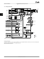
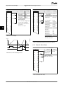
Illustration 4.5 Motor Connection
88
DC91
L1
95
I
N
S
96
U
97
V
89
DC+
81
R-
8
R+
98
W
99
RELAY 1
A
RELAY 2
M
93
L3
130BD577.10
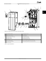
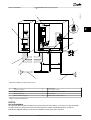
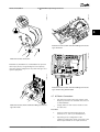
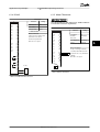
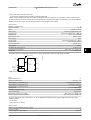
Illustration 4.6, Illustration 4.7 and Illustration 4.8 represent
mains input, motor, and grounding for basic frequency
converters. Actual configurations vary with unit types and
optional equipment.
L1
91 L2 L3
92
93
92
L2
130BA390.11
Illustration 4.7 Motor, Mains and Ground Wiring for Enclosure
Types A4 and A5
+D
C
99
BR
- B
MO
Illustration 4.8 Motor, Mains and Ground Wiring for Enclosure
Types B and C Using Shielded Cable
U V TOR
W
4.7 AC Mains Connection
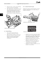
Illustration 4.6 Motor, Mains and Ground Wiring for Enclosure
Types A2 and A3
•
Size wiring based upon the input current of the
frequency converter. For maximum wire sizes see
8.1 Electrical Data.
•
Comply with local and national electrical codes
for cable sizes.
Procedure
1.
Connect 3-phase AC input power wiring to
terminals L1, L2, and L3 (see Illustration 4.9).
2.
Depending on the configuration of the
equipment, input power will be connected to the
mains input terminals or the input disconnect.
MG11AJ02 - Rev. 2013-07-31
15