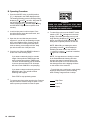
1
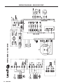
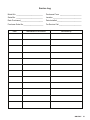
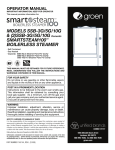
OPERATOR MANUAL
IMPORTANT INFORMATION, KEEP FOR OPERATOR
This manual provides information for:
MODELS SSB-3E/5E/10E
& (2)SSB-3E/5E/10E Domestic
SMARTSTEAM100™
BOILERLESS STEAMER
· Self Contained
· Electric Heated
· Capacity: SSB-3E=3 Steamer Pans Per Cavity
SSB-5E=5 Steamer Pans Per Cavity
SSB-10E=10 Steamer Pans Per Cavity
THIS MANUAL MUST BE RETAINED FOR FUTURE REFERENCE.
READ, UNDERSTAND AND FOLLOW THE INSTRUCTIONS AND
WARNINGS CONTAINED IN THIS MANUAL.
FOR YOUR SAFETY
Do not store or use gasoline or other flammable vapors
and liquids in the vicinity of this or any other appliance.
NOTIFY CARRIER OF DAMAGE AT ONCE
It is the responsibility of the consignee to inspect the container upon receipt of
same and to determine the possibility of any damage, including concealed damage. Unified Brands suggests that if you are suspicious of damage to make a
notation on the delivery receipt. It will be the responsibility of the consignee to file
a claim with the carrier. We recommend that you do so at once.
Manufacture Service/Questions 888-994-7636.
Information contained in this document is known to be current and accurate at the time
of printing/creation. Unified Brands recommends referencing our product line websites,
unifiedbrands.net, for the most updated product information and specifications.
PART NUMBER 145145, REV. L (1/10)
1055 Mendell Davis Drive
Jackson, MS 39272
888-994-7636, fax 888-864-7636
groen.com
OM-SSB-3E/5E/10EF
IMPORTANT –– READ FIRST –– IMPORTANT
WARNING:
THE UNIT MUST BE INSTALLED BY PERSONNEL QUALIFIED TO WORK WITH ELECTRICITY
AND PLUMBING. IMPROPER INSTALLATION CAN CAUSE INJURY TO PERSONNEL AND/OR
DAMAGE TO THE EQUIPMENT. THE UNIT MUST BE INSTALLED IN ACCORDANCE WITH
APPLICABLE CODES.
CAUTION:
SHIPPING STRAPS ARE UNDER TENSION AND CAN SNAP BACK WHEN CUT.
CAUTION:
DO NOT INSTALL THE UNIT IN ANY WAY WHICH WILL BLOCK THE REAR VENTS, OR
WITHIN 2 INCHES OF A HEAT SOURCE SUCH AS A BRAISING PAN, DEEP FRYER, CHAR
BROILER OR KETTLE.
CAUTION:
LEVEL THE UNIT FRONT TO BACK, AND PITCH IT SLIGHTLY TO THE FRONT, TO AVOID
DRAINAGE PROBLEMS.
WARNING:
FOLLOW THE WIRING DIAGRAM EXACTLY WHEN CONNECTING A UNIT TO AVOID
DAMAGE OR INJURY. WIRING DIAGRAM IS LOCATED ON THE INSIDE OF THE RIGHT
PANEL.
CAUTION:
DO NOT USE PLASTIC PIPE. DRAIN MUST BE RATED FOR BOILING WATER.
WARNING:
DO NOT CONNECT THE DRAIN DIRECTLY TO A BUILDING DRAIN.
WARNING:
BLOCKING THE DRAIN IS HAZARDOUS.
IMPORTANT: IMPROPER DRAIN CONNECTION WILL VOID WARRANTY.
IMPORTANT: DO NOT ALLOW ANY WATER TRAPS IN THE DRAIN LINE. A TRAP CAN CAUSE PRESSURE TO
BUILD UP INSIDE THE CAVITY DURING STEAMING, WHICH WILL MAKE THE DOOR GASKET LEAK.
2
WARNING:
WHEN YOU OPEN THE DOOR, STAY AWAY FROM STEAM COMING OUT OF THE UNIT.
STEAM CAN CAUSE BURNS.
WARNING:
BEFORE CLEANING THE OUTSIDE OF THE STEAMER, DISCONNECT THE ELECTRIC
POWER SUPPLY. KEEP WATER AND CLEANING SOLUTIONS OUT OF CONTROLS AND
ELECTRICAL COMPONENTS. NEVER HOSE OR STEAM CLEAN ANY PART OF THE UNIT.
WARNING:
ALLOW COOKING CHAMBER TO COOL COMPLETELY BEFORE CLEANING.
WARNING:
USE MILD CLEANING AGENTS ONLY. CAREFULLY READ THE WARNINGS AND FOLLOW
THE DIRECTIONS ON THE LABEL OF EACH CLEANING AGENT. USE SAFETY GLASSES
AND RUBBER GLOVES AS RECOMMENDED BY CLEANING AGENT MANUFACTURER.
WARNING:
DO NOT PUT HANDS OR TOOLS INTO THE COOKING CHAMBER UNTIL THE FAN HAS
STOPPED TURNING.
WARNING:
DO NOT OPERATE THE UNIT UNLESS THE REMOVABLE RIGHT SIDE PANEL HAS BEEN
RETURNED TO ITS PROPER LOCATION.
NOTICE:
DO NOT USE A CLEANING AGENT THAT CONTAINS ANY SULFAMIC ACID, OR ANY
CHLORIDE, INCLUDING HYDROCHLORIC ACID. IF THE CHLORIDE CONTENT OF ANY
PRODUCT IS UNCLEAR, CONSULT THE MANUFACTURER. DO NOT USE A CLEANING OR
DELIMING AGENT THAT CONTAINS MORE THAN 30% PHOSPHORIC ACID.
NOTICE:
DO NOT USE ANY DEGREASER THAT CONTAINS POTASSIUM HYDROXIDE OR SODIUM
HYDROXIDE OR THAT IS ALKALINE.
WARNING:
USE OF ANY REPLACEMENT PARTS OTHER THAN THOSE SUPPLIED BY GROEN OR THEIR
AUTHORIZED DISTRIBUTOR VOIDS ALL WARRANTIES AND CAN RESULT IN BODILY
INJURY TO THE OPERATOR AND DAMAGE THE EQUIPMENT. SERVICE BY OTHER THAN
FACTORY-AUTHORIZED PERSONNEL WILL VOID ALL WARRANTIES.
WARNING:
HIGH VOLTAGE EXISTS INSIDE CONTROL COMPARTMENTS. DISCONNECT FROM BRANCH
CIRCUIT BEFORE SERVICING. FAILURE TO DO SO CAN RESULT IN INJURY OR DEATH.
OM-SSB-E
2
OM-SSB-3E/5E/10EF
Table of Contents
OPERATOR WARNINGS......................................................................................................................................... 2
REFERENCES ......................................................................................................................................................... 3
EQUIPMENT DESCRIPTION................................................................................................................................... 4
INSPECTION AND UNPACKING ............................................................................................................................ 4
INSTALLATION AND STARTUP .......................................................................................................................... 5-8
OPERATION ......................................................................................................................................................... 8-9
CLEANING.......................................................................................................................................................... 9-10
MAINTENANCE ................................................................................................................................................ 11-12
TROUBLESHOOTING ...................................................................................................................................... 13-14
PARTS LIST........................................................................................................................................................... 15
WIRING DIAGRAM................................................................................................................................................ 21
SERVICE LOG ....................................................................................................................................................... 23
WARRANTY PROTECTION .................................................................................................................................. 24
References
UNDERWRITERS LABORATORIES, INC.
333 Pfingsten Road
Northbrook, Illinois 60062
NFPA/70
NATIONAL FIRE PROTECTION ASSOCIATION
60 Batterymarch Park
Quincy, Massachusetts 02269
The National Electrical Code
NSF INTERNATIONAL
789 N. Dixboro Rd.
P.O. Box 130140
Ann Arbor, Michigan 48113-0140
3
OM-SSB-E
3
OM-SSB-3E/5E/10EF
Equipment Description
Your Groen SSB-3E/5E/10E or (2)SSB-3E/5E/10E
SmartSteam100 Boilerless Steamer is designed to
give years of service. It has a stainless steel cavity
(cooking chamber) which is served by an electricheated atmospheric steam generating reservoir. A
powerful blower circulates the steam in the cavity to
increase heating efficiency.
The drain system on all models includes a spray
condenser, which cools drain water.
Each cavity holds up to three, five or ten steam table
pans (12” x 20” x 21/2” deep) as shown below.
SSB
Steamer
SSB-3E
(2)SSB-3E
SSB-5E
(2)SSB-5E
SSB-10E
(2)SSB-10E
PANS PER CAPACITY PER TYPE
12 x 20 x 2-1/2
(steamer)
3
6
5
10
10
20
12 x 20 x 4
(steamer)
2
4
3
6
6
12
13 x 18 18 x 26
(half size (bake)
bake)
0
0
0
0
20
40
0
0
0
0
10
20
An 18-guage stainless steel case encloses the
cavity, the steam generating reservoir and the control
compartment that houses electrical components.
Door hinges are field-reversible (the door may be set
to open from the left or right). Operating controls are
on the front panel.
The SSB-3E/5E/10E steamers are equipped with fully
electronic controls. These units are readily identified
by their unique control panels. Steamer function is
controlled by touch pad controls and a rotary timer-dial.
Inspection and Unpacking
Your Groen SmartSteam100 Boilerless Steamer will be
delivered completely assembled in a heavy shipping
carton strapped to a skid. On receipt, inspect carton
carefully for exterior damage.
SSB Steamer
CAUTION
SHIPPING STRAPS ARE UNDER TENSION AND
CAN SNAP BACK WHEN CUT.
Carefully cut the straps and detach the sides of the
carton from the skid. Pull the carton up off the unit. Be
careful to avoid personal injury or equipment damage
from staples which might be left in the carton walls.
OM-SSB-E
Weight (KGS)
220
100
SSB-3E W/Stand
310
141
(2) SSB-3E W/Stand
500
227
SSB-5E Table Top
275
125
SSB-5E W/Stand
350
159
(2)SSB-5E W/Stand
555
252
SSB-10E W/Stand
469
213
(2)SSB-10E W/Stand
764
347
When starting installation, check packing materials to
make sure loose parts such as the condensate drip
tray are not discarded with this material.
Write down the model number, serial number and
installation date. Keep this information for reference.
Space for these entries is provided at the top of the
Service Log in the back of this manual.
4
Weight (LBS)
SSB-3E Table Top
4
OM-SSB-3E/5E/10EF
Installation and Startup
WARNING
THE UNIT MUST BE INSTALLED BY PERSONNEL WHO ARE QUALIFIED TO WORK WITH ELECTRICITY
AND PLUMBING. IMPROPER INSTALLATION CAN CAUSE INJURY TO PERSONNEL AND/OR DAMAGE TO
THE EQUIPMENT. THE UNIT MUST BE INSTALLED IN ACCORDANCE WITH APPLICABLE CODES.
CAUTION
DO NOT INSTALL THE UNIT WITH THE REAR VENTS BLOCKED OR WITHIN 2 INCHES OF A HEAT SOURCE
SUCH AS A BRAISING PAN, DEEP FAT FRYER, CHARBROILER OR KETTLE.
TO AVOID DRAINAGE PROBLEMS, LEVEL THE UNIT FRONT TO BACK, AND PITCH SLIGHTLY TO
THE FRONT.
1. Installation
C.
Minimum Clearances: SmartSteam100 Boilerless
Steamer requires the following minimum
clearances to any surface, combustible or noncombustible.
Right Side
Left Side
Rear
2 inches
2 inches
6 inches
Steam Free Zone: The SmartSteam100 Boilerless
Steamer can be damaged by steam from
external sources. Do not install the steamer
over a steam venting drain. Ensure that steam is
not present in an area bounded by the footprint
of the steamer and a circle 18 inches in radius
about the right rear corner of the steamer (see
figure below).
Refer to steamer wiring diagram and element
wiring on pages 19 and 20 for wiring
information.
CAUTION
EACH UNIT MUST HAVE A SEPARATE GROUND
WIRE FOR SAFE OPERATION.
D.
7
E.
m
F.
Electrical Supply Connection
A.
Panel Removal - Right Side
Open the wiring and control panel by
removing screws from the right side panel.
Slide the panel forward and set it aside.
B.
Supply Wire
The equipment grounding wire must comply
with the National Electrical Code (NEC)
requirements. The wiring diagram on the
inside of the unit’s right side cover gives
directions for proper connection of the
terminal block jumpers. The wire must
be used or the unit will not meet Underwriters
Laboratories and NEC requirements. The
electric hole is sized for a one-inch conduit
fitting.
m
2.
Terminal Block
The terminal block for incoming power is
located at the back of the control compartment.
The ground terminal is located in the wiring
compartment near the terminal block.
18 -inch
radius
45
Phase Selection
Branch Circuit Protection
Each SmartSteam100 Boilerless Steamer,
including individual units of stacked models,
should have its own branch circuit protection
and ground wire.
Supply Voltage
The unit must be operated at the rated
name plate voltage. The name plate can be
found on the rear of the unit.
OM-SSB-E
5
OM-SSB-3E/5E/10EF
WARNING
TO AVOID DAMAGE OR PERSONAL INJURY,
FOLLOW THE WIRING DIAGRAM EXACTLY
Current and power demands for each unit are as
shown below.
ELECTRICAL SUPPLY CONNECTIONS
SSB Steamer
(KW RATING)
SSB-3E (9)
SSB-5E (12)
SSB-10E (21)
3.
RATED CURRENT DEMAND PER CAVITY
208 3P
25
34
59
208 1P
44
58
NA
Water Connection(s)
Install a check valve to prevent back flow
in the incoming cold water line, as required
by local plumbing codes. Water pressure
in the line should be between 30 and 60 PSI. If
pressure is above 60 PSI, a pressure regulator
will be needed. These pressures must provide
the 1.5 gallons per minute required for proper
steamer function.
A 3/4 inch female NH connector (garden hose
type) is used to attach the water supply to the
inlet valve. Minimum inside diameter
of the water feed line is 1/2 inch.
Use a washer in the hose connection. Do
not allow the connection to leak, no matter
how slowly. Do not over-tighten hose
connections.
6
22
29
51
38
50
NA
480 3P
11
15
26
SSB-Steamer
Drain ID Hose Size
Required (IN)
SSB-3E
1.5”
(2)SSB-3E
2.5”
SSB-5E
1.5”
(2)SSB-5E
2.5”
SSB-10E
2.0”
(2)SSB-10E
2.0”
There must be a free air gap between the end of the
hose and the building drain. The free air gap should
be as close as possible to the unit drain. There must
also be no other elbows or other restrictions between
the unit drain and the free air gap.
Drain Connection
Level the steamer front to back, and pitch it
slightly to the front (maximum 1/4 inch) by
adjusting the optional legs or the bullet feet
on the optional stand.
OM-SSB-E
240 1P
WARNING:
DO NOT CONNECT THE DRAIN DIRECTLY TO
A BUILDING DRAIN. BLOCKING THE DRAIN IS
HAZARDOUS.
This equipment is to be installed to comply
with the basic plumbing code of the Building
Officials
and
Code
Administrators
International, Inc. (BOCA) and the Food
Service Sanitation Manual of the Food and
Drug Administration (FDA).
4.
240 3P
CAUTION
DO NOT USE PLASTIC PIPE. DRAIN MUST BE
RATED FOR BOILING WATER.
6
OM-SSB-3E/5E/10EF
Install the drain line with a constant downward pitch.
IMPORTANT: Do not allow water traps in the line.
A trap can cause pressure build-up in the cavity,
which may cause the door gasket to leak.
B.
Electrical Supply Connection
Separate electrical connections will be
required for each steamer to be stacked. Each
steamer unit must have it’s own branch
circuit protection.
C.
Drain Connection
Steamers must be leveled front to back, and
pitched to the rear (maximum 1/4 inch) by
adjusting the bullet feet on the cabinet or
stand base.
For all factory-stacked SSB steamers,
a 21/2 inch ID hose is attached to the
unit drain. It must be rated for boiling water.
6.
Counter-Mounted Units
This section is applicable if the steamer will
be mounted to a counter. All four edges of the
bottom of the steamer must be sealed
with RTV to the counter if the 4 inch
legs are not used. Counter must be made
of a noncombustible material such as
metal or tile.
WARNING:
DO NOT STACK SSB STEAMERS WHEN LEGS
ARE USED.
Proper Drain Line Connection – Drain Line must
have a constant downward pitch of at least 1/4”
per foot. Observe local code regarding air gap
spacing and drain connections.
5.
Factory-Stacked Units
This section is applicable only if you are
installing factory-stacked units.
Installing stacked steamers is similar
to installing a single unit. The steamers
are stacked and assembled at the factory
and delivered with the water connections and
drain hoses required for a single point
connection.
A.
Water Connection
The same water supply connection
is used for both units. At the water
inlet valve a 3/4 inch female NH connector
(gardenhosetype)isusedforthewatersupply.
7
OM-SSB-E
7
OM-SSB-3E/5E/10EF
Initial Startup
After the SmartSteam100 Boilerless Steamer has been
installed, test it to ensure that the unit is operating
correctly.
1.
Remove all literature and packing materials
from the interior and exterior of the unit.
2.
Make sure the water supply line is open.
3.
Turn on electrical service to the unit. The
steamer will not operate without electrical power.
Do not attempt to operate the unit during a power
failure.
NOTE: The door MUST be closed for the elements
to operate.
4.
To turn unit on, press the ON switch on the
control panel.
5.
When the steam generating reservoir has
filled with water, the heaters will begin
heating automatically. Within 20 minutes
or less the READY light will come on,
indicating that the water has reached
its standby temperature. When the READY
light is displayed, you may take any one
of the following steps:
a. Push TIMED and set the timer knob to
the desired steaming time.
b. Push MANUAL for continuous
steaming.
c.
Push STOP to let the unit stay at
ready condition.
WARNING
WHEN YOU OPEN THE DOOR, STAY AWAY
FROM STEAM COMING OUT OF THE UNIT.
STEAM CAN CAUSE BURNS.
8
OM-SSB-E
8
6. To shut down the unit, press the OFF switch.
The steam generating reservoir will then fill
with cold water and drain.
7. If the steamer operates as described, the unit
is functioning correctly and ready for use.
OM-VRC-3E/VRC-6E
Operation
A. Controls
Operator controls are on the front right of the unit.
The control panels have the following touch pads and
indicator lights:
s The TIME display shows the remaining cooking time. It
displays three dashes in MANUAL mode.
s The ON/OFF rocker switch gets the SmartSteam100 ready for
use or shuts it off.
s The READY indicator light indicates the unit has
achieved the ready temperature.
s Hour meter records cumulative hours of operation.
s The FAULT display shows the current fault.
TIME display
TIMER knob
MANUAL button
and indicator
TIMED button
and indicator
STOP button
and indicator
The push button operations:
CANCEL button
and indicator
1. In the STOP mode the steam generator stays at a low boil
or ready temperature.
2. When the TIMED button is pushed , the TIMED light will illuminate
and time can be set by turning the TIMER knob (cook time can be increased
or decreased at any time by turning the timer knob). The unit steams until
the timer counts down to zero and the temperature drops to ready.
At that time the STOP light illuminates and a beeper sounds.
3. When the MANUAL button is pushed, the unit steams continuously.
The MANUAL light will stay illuminated.
4. CANCEL button should be pushed to stop beeping.
FAULT display
READY indicator
ON/OFF
rocker switch
Hour meter
OM-SSB-E
9
B. Operating Procedure
1. Press the ON/OFF rocker to the ON position,
(Fi_) is displayed in the TIME display window.
The steam generating reservoir will begin filling,
displaying (Fi_) and (Fi_) as it fills. After initial fill
the unit will begin draining displaying (Fi_),
refilling displaying (Fi_), and then begin heating
until the READY light comes on (about 15-20
minutes).
WARNING
WHEN YOU OPEN THE DOOR, STAY AWAY
FROM THE STEAM COMING OUT OF THE UNIT.
THE STEAM CAN CAUSE BURNS.
2. Load food into pans in uniform layers. Pans
should be filled to about the same levels, and
should not be mounded.
6. To shut off the unit press the ON/OFF rocker
switch to OFF, (FL_) will appear in the timer
display. The steam generating reservoir will
begin draining, displaying (Fi_) and (Fi_) as it
drains, and refill to the high float twice and
finally drain completely and turn off the unit.
3. Open the door and slide the pans into the
supports. If you will only be steaming one pan,
put it in the middle position. Some foods will
cause foam. When cooking foods that foam,
such as shrimp, put an empty solid 2½” deep
pan in the bottom slot of the pan racks.
NOTE: When filling or draining the steam
generating reservoir (_) will be displayed
indicating the water level in the reservoir.
(_) reservoir is empty, (_) low float is satisfied,
(_) high float is satisfied.
4. Close the door. When the READY indicator is
lit take one of the following steps:
If you want to steam the food for a certain
length of time push the TIMED button and
set the desired time with the TIMER knob.
The timer will automatically run the steamer
for the set time and then STOP. A beeper
will sound. Push CANCEL to stop beeping.
NOTE: If a large amount of shrimp is cooked
in the SmartSteam100 foaming will occur
because the steam lid actually gets so hot
that the shrimp will cook on its surface and
the shrimp proteins in the dripping will foam
on the surface of the steam lid.
If you want to steam continuously push the
MANUAL button. The unit will continue
steaming until stopped.
* To avoid this use a catch pan to catch shrimp
drippings and proteins to prevent foaming
when cooking a large amount of shrimp.
Push STOP to stop producing steam.
5. To remove pans from cavity open the door. Remove
the pans from the steamer using hot pads or oven
mitts to protect your hands from the hot pans.
High Float
Low Float
Empty
10
OM-SSB-E
10
OM-SSB-3E/5E/10EF
Cleaning
To keep your SmartSteam100 Boilerless Steamer in proper working condition, use the following procedure to clean the
unit. This regular cleaning will reduce the effort required to clean the steam generator and cavity.
A.
Suggested Supplies
1.
2.
3.
4.
5.
6.
7.
8.
9.
10.
Mild detergent
Stainless steel exterior cleaner Groen
Spray DeGreaser (Part Number
140830WS)
Cloth or sponge
Brush with soft bristles
Spray bottle
Measuring cup
Nylon pad
Towels
Plastic disposable gloves
Funnel
B.
Procedure
1.
Exterior Cleaning
WARNING
DISCONNECT THE POWER SUPPLY
BEFORE CLEANING THE OUTSIDE OF
THE STEAMER.
KEEP
WATER
AND
CLEANING
SOLUTIONS OUT OF CONTROLS AND
ELECTRICAL COMPONENTS. NEVER
HOSE OR STEAM CLEAN ANY PART OF
THE UNIT.
AVOID
CONTACT
WITH
ANY
CLEANERS, DELIMING AGENT OR
DEGREASER AS RECOMMENDED BY
THE SUPPLIER. MANY ARE HARMFUL.
READ THE WARNINGS AND FOLLOW
THE DIRECTIONS!
EVEN WHEN THE UNIT HAS BEEN SHUT
OFF, DON’T PUT HANDS OR TOOLS
INTO THE COOKING CHAMBER UNTIL
THE FAN HAS STOPPED TURNING.
a. Prepare a warm solution of the mild detergent
as instructed by the supplier. Wet a cloth with
this solution and wring it out. Use the moist
cloth to clean the outside of the unit. Do not
allow freely running liquid to touch the
controls, the control panel, any electrical
part, or any louver on the rear panels.
DON’T OPERATE THE UNIT UNLESS
THE REMOVABLE PARTITION HAS
BEEN PUT BACK IN ITS PROPER
LOCATION.
b. To remove material which may be stuck to
the unit, use a fiber brush or a plastic or
rubber scraper with a detergent solution.
DON’T USE ANY CLEANING AGENT
THAT CONTAINS ANY SULFAMIC
AGENT OR ANY CHLORIDE, INCLUDING
HYDROCHLORIC ACID (HCL). TO
CHECK FOR CHLORIDE CONTENT SEE
ANY MATERIAL SAFETY DATA SHEETS
PROVIDED BY THE CLEANING AGENT
MANUFACTURER.
c. Stainless steel surfaces may be polished with
a recognized stainless steel cleaner.
2.
Interior Cleaning
Daily cleaning must be done in order to enhance the
performance and prolong the life of your SmartSteam
Boilerless Steamer.
IMPORTANT
DO NOT USE ANY METAL MATERIAL (SUCH AS METAL SPONGES) OR METAL IMPLEMENTS (SUCH
AS A SPOON, SCRAPER OR WIRE BRUSH) THAT MIGHT SCRATCH ANY STAINLESS STEEL SURFACE.
SCRATCHES MAKE THE SURFACE HARD TO CLEAN AND PROVIDE PLACES FOR BACTERIA TO
GROW. DO NOT USE STEEL WOOL, WHICH MAY LEAVE PARTICLES EMBEDDED IN THE SURFACE,
WHICH COULD EVENTUALLY CAUSE CORROSION AND PITTING.
11
OM-SSB-E
11
WARNING! ALLOW THE STEAMER TO COOL
COMPLETELY
BEFORE
CLEANING.
HOT
SURFACES CAN CAUSE SEVERE BURNS.
CLEANING STEPS:
STEP 1 - Press OFF switch to turn steamer
OFF and open steamer door.
High Water Float
(swings down)
Low Water Float
(swings up)
STEP 2 - CAUTION: allow the steamer to cool
completely before cleaning.
Strainer
STEP 3 - Remove steam lid by grasping the two tabs
located on the lid front and sliding pan forward.
STEP 4 - Remove left pan rack by lifting rack up and
pulling away from cavity wall.
STEP 5 - Remove right fan shroud and rack assembly
by lifting rack up and pulling away from cavity wall.
DELIMING INSTRUCTIONS:
STEP 6 - Clean steam lid, left pan rack and rack/
shroud assembly to remove food soils. These three
parts may be cleaned in a dishwasher.
•
When using Groen Boilerless Water Filtration
System use vinegar as a deliming agent.
STEP 7 - Use a mild detergent to wipe down the entire
steamer cavity to remove food and scale particles.
Carefully clean float probes if food residue or loose
scale is present. A thin layer of tightly bound scale
is normal and will not affect steamer performance. If
scale is excessive, then refer to deliming instructions
below.
STEP 1 - After following all cleaning steps 1 through
7 listed above, turn steamer on and allow water to
enter steamer cavity.
STEP 8 - Remove drain strainer and clean thoroughly
to remove any build-up of debris.
STEP 2 - Pour 1 cup of vinegar or delimer into
steamer cavity and shut door.
STEP 9 - Replace pan racks and steam lid. Steamer
is now cleaned and ready to use.
STEP 3 - Set steamer timer to 30 minutes and allow
steam cleaning to occur.
•
Groen approved delimer may be used to
remove excessive scale build-up.
STEP 4 - After 30 minutes cleaning cycle is complete,
turn steamer OFF and allow to cool completely.
FAILURE TO CLEAN THE STEAMER AS
SPECIFIED COULD NEGATIVELY IMPACT
THE PERFORMANCE OF THE STEAMER.
STEP 5 - Open steamer door and wipe down the
entire steamer cavity to remove loosened scale
particles. Carefully clean float probes if loose scale
is present.
STEP 6 -Replace pan racks and steam lid. Steamer
is now cleaned and ready to use.
12
OM-SSB-E
12
OM-SSB-3E/5E/10EF
Maintenance
3. Adjust the door latch pin to allow for changes
that might occur as the gasket ages.
The SmartSteam100 Boilerless Steamer is designed for
minimum maintenance and no user adjustments
should be necessary. Certain parts may need
replacement after prolonged use. If there is a need
for service, only Groen Authorized Service Agents
should perform the work.
a. Loosen the lock nut at the base of the latch
pin, then turn the latch pin 1/4 turn clockwise,
and tighten the lock nut.
If steam or condensate is seen leaking from around
the door, take the following steps:
b. After adjustment, run the unit to test for further
steam leakage.
1. Check the door gasket. Replace it if it is cracked
or split.
c. If there is still leakage, repeat the adjustment
d. Continue adjusting the pin clockwise until
the door fits tightly enough to prevent
leakage. The hinge may also be adjusted.
2. Inspect the cooking chamber drain to be sure it
is not blocked.
Troubleshooting
Your Groen SmartSteam100 Boilerless Steamer is designed to operate smoothly and efficiently if properly maintained.
However, the following is a list of checks to make in the event of a problem. Wiring diagrams are furnished inside
the service panel. If an item on the check list is marked with (*), it means that the work should be done by a Groen
Authorized Service Agent.
SYMPTOM
WHO
WHAT TO CHECK
1. Fault Display 1 or 2
User
a. Clean floats in unit / Check float probe orientation
b. Be sure water supply is adequate to run steamer(s)
during normal operation.
2. No power.
User
a. Check wall circuit breaker.
b. Disconnect power, then check fuses inside steamer. *
c. Call service technician.
3. Unit overfills with
water at start up.
User
a. Clean floats in unit / Check float probe orientation.
b. Clean drain strainer.
c. Call service technician.
4. Steamer does not fill
with water.
User
a.
b.
c.
d.
e.
5. “Door” Shown in Time
Display Window
User
a. Is the steamer door securely closed?
6. No steam.
User
a.
b.
c.
d.
7. Fault Display 7
User
a. The component cooling fan may not be operating.
The display may come on for several minutes during
normal operation. If it stays on for more than 30 minutes,
call service technician. Unit may be used for cooking,
while waiting for service.
Is the ON switch depressed?
Is the water supply connected?
Is the water turned on?
Is the water supply hose kinked or obstructed?
Check for low water pressure (less than 30 PSI) or low water
flow (less than 1.5 gpm).
f. Is the screen at the water connection clogged?
Is the ON switch depressed?
Is the water supply connected?
Is the water turned on?
Is steamer door completely closed?
13
OM-SSB-E
13
OM-SSB-3E/5E/10EF
14
8. Any unusual
operation.
User
a. Press OFF switch to turn steamer off. Momentarily turn
circuit breaker off and then turn unit back on.
9. Door pops open.
User
a. Ensure drain and vent are not plugged. No more than two
units should be attached to a single drain line.
b. Check door pin adjustment per above.
c. Call service technician.
10. Fault Display 6
User
a. Wait 30 minutes for unit to cool down.
b. Call service technician.
OM-SSB-E
14
PARTS LIST – SSB-3E/5E/1OEF
OM-SSB-E
15
PARTS LIST – SSB-3E/5E/1OEF
16
OM-SSB-E
PARTS LIST – SSB-3E/5E/1OEF
OM-SSB-E
17
PARTS LIST – SSB-3E/5E/1OEF
18
OM-SSB-E
PARTS LIST – SSB-3E/5E/1OEF
OM-SSB-E
19
PARTS LIST – SSB-3E/5E/1OEF
To order parts, contact your Groen Authorized Service Agent. Supply the model designation, serial
number, part description, part number, quantity, and when applicable, voltage and phase.
Key Description
Part No.
Key Description
1 Terminal Block
2 Capacitor, 3MF
3 Transformer 208/240v Primary/
24v secondary, 75VA
4 Contactor
5 Fuseholder
6 Fuse
7 Ground Terminal (3E/5E)
Ground Terminal (10E)
8 Terminal Block (3E/5E)
Terminal Block (10E)
9 Water Valve
10 Muffin Fan
11 Drain Box (3E/5E)
Drain Box (10E)
12 Hi-Limit
13 Thermostat (drain box)
14 Drain Valve
15A Condensate Cup
15B Gasket, condensate cup
16 Ready Thermostat
17 Water Level Probe (Serial Number
MSA and MSB)
Float Probe (Serial Number
MSC and Following)
18 Door Switch
19 Power Switch
20 Door Assembly, Complete (3G)
Door Assembly, Complete (5G)
Door Assembly, Complete (10G)
21 Knob
22 Control Board
23 Tooroid (480V only)
24 Motor Assembly
25 Relay Board
26 Element 208v 1000w (3E/5E)
Element 240v 1000w (3E/5E)
Element 277v 1000w (3E/5E)
Element 208v 1000w (10E)
Element 240v 1000w (10E)
Element 277v 1000w (10E)
27 Top Panel (3E/5E)
Top Panel (10E)
070185
096813
121716
28
29
30
31
32
33
34
35
36
x
x
x
x
x
x
x
x
x
x
x
x
x
x
x
x
x
x
x
20
145081
096809
119823
106412
129714
003888
002577
071235
153505
150659
150661
144484
145248
071234
150628
142613
147285
142689
149880
096857
160920
130858
125922
143874
160921
160648
119833
146880
160649
148553
148554
148552
148444
148551
148443
150637
149444
x- Item not depicted/called out in drawing or photograph
OM-SSB-E
Part No.
Front Panel Overlay (3E)
153015
Front Panel Overlay (5E/10E)
153472
Door Latch Pin
078914
Door Pin Lock Nut
003823
Steam Lid (3E/5E)
149299
Steam Lid (10E)
149452
Cavity Fan
096790
Left Pan Rack (3E)
149883
Left Pan Rack (5E)
149872
Left Pan Rack (10E)
145642
Door Handle
129723
Door Gasket (3E)
124849
Door Gasket (5E)
125907
Door Gasket (10E)
143879
Terminal Block 480v Only (10E)
003888
Motor Shaft Seal
096868
Blower Cover (3E)
149387
Blower Cover (5E)
149313
Blower Cover (10E)
149451
Right Pan Rack (3E)
141571
Right Pan Rack (5E)
140157
Right Pan Rack (10E)
145721
Drip Tray (3E/5E)
094151
Drip Tray (10E)
145520
Left Side Panel (3E)
149229
Left Side Panel (5E)
149233
Left Side Panel (10E)
149446
Right Side Panel (3E)
149231
Right Side Panel (5E)
149235
Right Side Panel (10E)
149448
Flow Reducer, Condensate
147371
Flow Reducer, Fill
144481
Harness, Control To Relay
160884
Board SSB
Harness, SSB Rear (3E/5E)
160883
Harness, SSB Low Voltage (3E/5E) 160880
Harness, SSB Foward (3E/5E)
160882
Harness, Steamer High Voltage (3E/5E)160874
Harness, SSB High Voltage
153486
Jumper, Voltage Select
123124
Harness, SSB-10E Low Voltage
153841
Harness, SSB-10E Forward
153842
Harness, SSB-10E Rear
153843
Harness, Steamer 480v only
153118
WIRING DIAGRAM – SSB-3E/5E/1OEF
OM-SSB-E
21
WIRING DIAGRAM – SSB-3E/5E/1OEF
22
OM-SSB-E
OM-SSB-3E/5E/10EF
Service Log
Model No. ___________________________
Purchased From ______________________
Serial No. ___________________________
Location _____________________________
Date Purchased_______________________
Date Installed _________________________
Purchase Order No.____________________
For Service Call _______________________
Date
Maintenance Performed
15
Performed by
OM-SSB-E
23
OM-SSB-3E/5E/10EF
GROEN LIMITED WARRANTY TO COMMERCIAL PURCHASE*
(U.S. & Canadian Sales Only)
Groen warrants to original commercial purchaser/users that foodservice equipment manufactured by Groen (“Groen
Equipment”) other than CapKold foodservice equipment, shall be free from defects in material and workmanship for (i)
2000 actual operating hours (provided that such equipment has a device that has recorded actual operating hours since
the installation of such equipment), (ii) twelve (12) months from the date of installation or (iii) fifteen (15) months from the
date of shipment from Groen, whichever firs occurs (the “Warranty Period”), in accordance witht he following terms and
conditions:
I.
This warranty is limited to replacement parts and related labor for Groen Equipment located at its original place of
installation in the United States and Canada.
II.
Damage to Groen Equipment that occurs during shipment must be reported to the carrier and is not covered under
this warranty. The reporting of any damage during shipment is the sole responsibility of the commercial purchaser/user of
such Groen Equipment.
III.
For Groen Convection Combo™ Steamer-Ovens, HyPerSteam™ Convection Steamers and HyPlus™ Pressureless
Steamers, Groen further warrants to the original commercial purchaser/users of such Groen Equipment that the atmospheric
steam generators or boilers contained in such Groen Equipment shall be free from defects in material and workmanship
for (i) 4000 actual operating hours (provided that such equipment has a device that has recorded actual operating hours
since since the installation of such equipment), (ii) twenty-four (24) months from the date of installation or (iii) twenty-seen
(27) months from date of shipment from Groen, whichever first occurs, provided that: (a) the original purchaser/user shall
have also purchased and installed a Groen PureSteem™ Water Treatment System for use in connection with such Groen
Convection Combo Steamer-Oven, HyPerSteam Convection Steamer or HyPlus Pressureless Steamer on or before teh
date such Groen Equipment was installed, (b) the original purchaser/user has continuously used such Water Treatment
System in connection with such Groen Equipment from the date of installation, and (c) the commercial purchaser/user
shall have maintained such Water Treatment System in accordance with the maintenance and filter cartridge replacement
recommendations of Groen, and otherwise maintained such Oven or Steamer in accordance with all other operational and
maintenance recommendations of Groen.
IV.
For Groen SmartSteam100™ Boilerless Steamers and Vortex100™ Connectionless Steamers, Groen further warrants to
the original commercial purchaser/users of SmartSteam™ Boilerless Steamers and Vortex™ Connectionless Steamers
shall be free from defects in material and workmanship for (i) 4000 actual operating hours (provided that such equipment
has a device that has recorded actual operating hours since the installation of such equipment), (ii) twenty-four (24)
months from the date of installation or (iii) twenty-seven (27) months from the date of shipment from Groen, whichever first
occurs. This warrants Groen Vortex100 Connectionless Steamers that were shipped after March 15, 2004, and SmartSteam100
Boilerless Steamers that were shipped after May 1, 2003.
V.
Groen further warrants to the original commercial purchaser/users of Groen Convection Combo Steamer-Ovens
that the electronic relay and control board contained in such Groen Convection Combo Steamer-Oven shall be free from
defects in material and workmanship for (i) 4000 actual operating hours (provided that such equipment has a device that
has recorded actual operating hours since the installation of such equipment), (ii) twenty-four (24) months from the date
of installation or (iii) twenty-seven (27) months from the date of shipment from Groen, whichever first occurs.
24
OM-SSB-E
16
VI.
During the Warranty Period, Groen, directly or through its authorized service representative, will either repair or
replace, at Groen’s sole election, any Groen Equipment determined by Groen to have a defect in material or workmanship.
As to any such warranty service during the Warranty Period, Groen will be responsible for related reasonable labor and
portal to portal transportation expenses (time & mileage) incurred within the United States and Canada.
VII.
This warranty does not cover boiler maintenance, calibration, periodic adjustments as specified in operating
instructions or manuals, consumable parts (such as scraper blades, gaskets, packing, etc.), and labor costs incurred
for removal of adjacent equipment or objects to gain access to Groen Equipment. This warranty does not cover defects
caused by improper installation, abuse, careless operation, or improper maintenance of Groen Equipment. This warranty
does not cover damage to Groen Equipment caused by poor water quality or improper boiler maintenance.
VIII. THIS WARRANTY IS EXCLUSIVE AND IS IN LIEU OF ALL OTHER WARRANTIES, EXPRESSED OR IMPLIED,
INCLUDING ANY IMPLIED WARRANTY OF MERCHANTABILITY OR FITNESS FOR A PARTICULAR PURPOSE, EACH
OF WHICH IS HEREBY EXPRESSLY DISCLAIMED. THE REMEDIES DESCRIBED ABOVE ARE EXCLUSIVE AND IN
NO EVENT SHALL GROEN BE LIABLE FOR SPECIAL, CONSEQUENTIAL, OR INCIDENTAL DAMAGES FOR THE
BREACH OR DELAY IN PERFORMANCE OF THIS WARRANTY.
IX.
Groen Equipment is for commercial use only. If sold as a component of another (O.E.M.) manufacturer’s equipment,
or if used as a consumer product, such Equipment is sold AS IS and without any warranty.
Cost of Extended Coverage.
Limited Extended Warranty Coverage is available on all standard Groen Equipment (other than CapKold
foodservice equipment) covered by the above Groen Limited Warranty. Commercial purchasers/users of Groen Equipment
may elect to extend the standard limited warranty to cover parts, labor and portal to portal transportation costs (time and
mileage) for an additional (i) 2000 actual operating hours, or (ii) twelve (12) month period, or for an additional (i) 4000
actual operating hours, or (ii) twenty four (24) month period, whichever first occurs, in addition to the time period of
the standard limited warranty described above. Limited Extended Warranty Coverage is not available to extend the
supplemental limited warranty for: (a) atmospheric steam generators or boilers contained in Groen Convection Combo
Steamer-Ovens, HyPerSteam Convection Steamers and HyPlus Pressureless Steamers, or (b) electronic relay and
control boards contained in Groen Convection Combo Steamer-Ovens, or (c) Groen SmartSteam100 Boilerless Steamers, or
(d) Vortex100 Connectionless Steamers
Five percent (5.0%) of the LIST PRICE of the Groen Equipment to be covered by the Limited Extended Warranty
for each additional twelve (12) months of limited extended warranty coverage. The five percent (5.0%) of the LIST PRICE
charge will be the net invoice amount for each year of Limited Extended Warranty Coverage purchased.
Conditions of Coverage
(1) Limited Extended Warranty Coverage must be purchased at the time the Groen Equipment to be covered is
purchased.
(2) All conditions and limitations on the Standard Limited Warranty Coverage apply to the Limited Extended Warranty
Coverage. See above for details of conditions and limitations on the Standard Warranty Coverage.
Covers Groen Equipment (other than CapKold foodservice equipment and Vortex Connectionless Steamers) ordered
after September 11, 2001.
OM-SSB-E
25
NOTES:
26
OM-SSB-E
NOTES:
OM-SSB-E
27
1055 Mendell Davis Drive s Jackson MS 39272
888-994-7636 s 601-372-3903 s Fax 888-864-7636
groen.com
PART NUMBER 145145, REV. L (1/10)