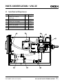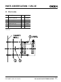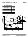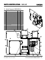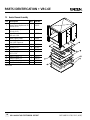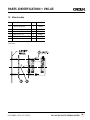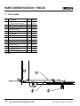
1
SERVICE MANUAL
IMPORTANT INFORMATION, KEEP FOR OPERATOR
This manual provides information for:
MODELS VRC-3E
& VRC-6E Domestic
VORTEX100 ®
CONNECTIONLESS
STEAMER
· Self Contained
· Electric Heated
· Capacity:
VRC-3E=3 Steamer Pans Per Cavity
VRC-6E=6 Steamer Pans Per Cavity
Information contained in this document is known to be current and accurate at the time
of printing/creation. Unified Brands recommends referencing our product line websites,
unifiedbrands.net, for the most updated product information and specifications.
PART NUMBER 145702, REV. C (01/07)
1055 Mendell Davis Drive
Jackson, MS 39272
888-994-7636, fax 888-864-7636
groen.com
Table of Contents
INTRODUCTION
Page
1.1
THE GROEN SERVICE CONCEPT .......................................................................................... 5
1.2
THE GROEN CERTIFIED SERVICE.......................................................................................... 5
1.3
WARRANTY AND NON-WARRANTY REPAIRS ...................................................................... 5
1.4
SAFETY ............................................................................................................................... 5-6
1.5
GLOSSARY OF TERMS ......................................................................................................... 6
1.6
TOOLS AND SUPPLIES ......................................................................................................... 6
1.6.1 Reqired Tools .......................................................................................................... 6
1.6.2 Recommended Instruments...................................................................................... 6
1.6.3 Helpful Hardware .................................................................................................... 6
1.6.4 Recommended Supplies ........................................................................................... 7
1.7
HOW TO USE THIS MANUAL ............................................................................................... 7
1.7.1 Technical Bulletins ......................................................................................................... 7
OPERATION
2.1
CONTROLS.......................................................................................................................... 9
2.2
OPERATING PROCEDURE .................................................................................................... 10
INSTALLATION, CLEANING
AND TESTING
3.1
INSTALLATION .................................................................................................................... 11-12
3.2
INSTALLATION CHECKLIST .................................................................................................. 13
3.3
CLEANING PROCEDURES .................................................................................................... 13-14
DIAGNOSTICS / TROUBLESHOOTING
4.1
TROUBLESHOOTING PROCEDURES & QUICK REFERENCE .................................................. 16-19
4.2
VRC CHECKOUT ................................................................................................................. 20
NUMBER
PART
145702, REV. BFOR
(7/06)
CALL 888-994-7636
TECHNICAL SUPPORT
Call 1-800/676-9040
for NUMBER
Technical 145702,
Support REV.
1 C (01/07)
i
PART
Table of Contents
ASSEMBLY / DISASSEMBLY
Page
5.1
AIR TEMPERATURE PROBE.................................................................................................. 21
5.2
CAVITY VENT ASSEMBLY .................................................................................................... 22
5.3
CONTROL PC BOARD .......................................................................................................... 22
5.4
DOOR REMOVAL/INSTALLATION/ALIGNMENT ..................................................................... 22
5.5
DOOR SWITCH .................................................................................................................... 23
5.6
DOOR REVERSING PROCEDURE .......................................................................................... 23
5.7
DOOR GASKET .................................................................................................................... 23-24
5.8
DOOR SPRING..................................................................................................................... 24
5.9
DOOR LOCKING PIN AND LOCK .......................................................................................... 24
5.10
DRAIN VALVE ASSEMBLY.................................................................................................... 24-25
5.11
FAN .................................................................................................................................... 25
5.12
HEATER ELEMENT ............................................................................................................... 25-26
5.13
HI-LIMIT THERMOSTAT........................................................................................................ 26
5.14
LEGS ................................................................................................................................... 26
5.15
MOTOR, FAN ASSEMBLY..................................................................................................... 27
5.16
MOTOR, STARTING CAPACITOR.......................................................................................... 28
5.17
PANEL BACK....................................................................................................................... 28
5.18
PANEL LEFT SIDE / RIGHT SIDE ............................................................................................ 28
5.19
PANEL, TOP COVER ............................................................................................................ 28
5.20
REMOTE READING THERMOMETER..................................................................................... 29
5.21
WATER LEVEL FLOAT........................................................................................................... 29
5.22
WATER DRAIN KIT INSTALLATION....................................................................................... 30-31
PART
REV. C (01/07)
Call 1-800/676-9040
for Technical Support
18 NUMBER
ii 145702,
145702,
REV. B (7/06)
CALL 888-994-7636PART
FORNUMBER
TECHNICAL
SUPPORT
Table of Contents
PARTS IDENTIFICATION • VRC-3E
Page
6.1
CAVITY VENT ASSEMBLY .................................................................................................... 32
6.2
CONTROL BOARD AND WIRING HARNESSES ...................................................................... 33
6.3
DOOR ASSEMBLY................................................................................................................ 34
6.4
ELECTRICAL COMPONENTS 208/240/240 VOLTS................................................................. 35
6.5
HEATER ELEMENTS.............................................................................................................. 36
6.6
MOTOR ASSEMBLY.............................................................................................................. 37
6.7
FLOAT ASSEMBLY ............................................................................................................... 38
6.8
INTERIOR & EXTERIOR CABINET.......................................................................................... 39
PARTS IDENTIFICATION • VRC-6E
7.1
CAVITY VENT ASSEMBLY .................................................................................................... 40
7.2
CONTROL BOARD AND WIRING HARNESSES ...................................................................... 41
7.3
DOOR ASSEMBLY................................................................................................................ 42
7.4
ELECTRICAL COMPONENTS 208/240/480 VOLTS................................................................. 43
7.5
HEATER ELEMENTS ............................................................................................................. 44
7.6
MOTOR ASSEMBLY ............................................................................................................. 45
7.7
FLOAT ASSEMBLIES ............................................................................................................ 46
7.8
INTERIOR & EXTERIOR CABINET .......................................................................................... 47
SPECIFICATIONS • VRC-3E, VRC-6E
GENERAL SPECIFICATIONS.................................................................................................. 48
ELECTRICAL SPECIFICATIONS.............................................................................................. 48
WIRING DIAGRAM .............................................................................................................. 49
LADDER DIAGRAM .............................................................................................................. 50
NUMBER
PART
145702, REV. BFOR
(7/06)
CALL 888-994-7636
TECHNICAL SUPPORT
PART
Call 1-800/676-9040
for NUMBER
Technical 145702,
Support REV.
1 C (01/07)
iii
INTRODUCTION
1.1 The Groen Service Concept
1.3 Warranty & Non-Warranty Repair
Since 1907 Groen has been in the business of designing and
manufacturing the finest commercial appliances for the food
service industry. Chefs, cooks and kitchen support personnel
have come to depend upon the quality of construction and
the reliability of operation.
Groen Warranty provisions are clearly presented in the
customer’s Operator Manual.
Groen, in turn, depends upon our service centers and their field
service personnel to keep the equipment in top operating condition. In order to do this, our designs are made with service and
reliability in mind.
Once the Groen equipment is sold, manufactured, delivered and
installed, our reputation is clearly in your hands. As part of our
team, we value your efforts and input to our product design.
We will do all we can to make your job of keeping the equipment in perfect working order as easy as we can. Together, we
will keep our customers satisfied.
1.2 Groen Certified Service
The Vortex100 Connectionless Steamer has been carefully designe
d
to provide many years of efficient and reliable service. Part of the
quality program is Groen Certified Service. This includes:
• Groen certifies that all equipment delivered to our customers
has been inspected and tested for compliance with the
specifications.
• Groen certifies that all parts required for service and
maintenance will be readily available.
• Groen certifies that this manual will be updated by means of
periodic service bulletins to provide the most up-to-date
information for field maintenance and service personnel.
PART
REV. C (01/07)
Call 1-800/676-9040
for Technical Support
1 NUMBER
1 145702,
Certain procedures for the cleaning and/or adjustment
of the Vortex Connectionless Steamer are presented in this manual for reference, but not warranty related.
This non-warranty symbol is used throughout the
manual to tell you which items and activities are
NOT covered by the equipment warranty.
1.4 Safety
The Groen Vortex100 Connectionless Steamer has been designed
from the start with safety in mind. This includes safety to the
operating and maintenance personnel, safety to the facility in
which the equipment is installed and safety to the equipment
itself.
The steamer has been designed to the highest industry standards
and has been certified by the National Sanitation Foundation
Testing Laboratory (NSF) and the Underwriters Laboratory (UL)
to assure strict compliance.
The steamer contains several devices, which are specifically used
to prevent unsafe conditions. If they are disconnected, make sure
they are reinstalled properly and tested before the steamer is
operated.
The safety precautions in this manual are in accordance with
ANSI 535 Standard. Three different signal words alert you to a
hazardous situation: DANGER, WARNING, AND CAUTION
DANGER: The signal word DANGER indicates that a
hazardous situation is about to happen and, if not avoided,
will result in death or serious injury.
• Do not store or use gasoline or other flammable vapors and
liquids in the vicinity of this or any other appliance.
• When you open the steamer door, be very careful to avoid
escaping steam. Steam can cause burns.
• After removing the fan baffle partition, do not put your
hands or other object into the cooking cavity until the fan
comes to a complete stop. Rotating fan blades can cause
severe injury!
145702,
REV. C (7/06)
CALL 888-994-7636PART
FORNUMBER
TECHNICAL
SUPPORT
INTRODUCTION
WARNING: The signal word WARNING tells you that a
possibly hazardous situation is about to take place which, if not
avoided, could cause death or serious injury.
• Always turn off the steamer power before removing
and partitions or panels.
• Disconnect the steamer from the power source before
performing and internal service work.
CAUTION: The signal word CAUTION warns you of a
hazardous situation which, if not avoided, may result in minor
or moderate injury.
• Steamer may be hot. Take precautions to prevent any contact
with hot surfaces.
• Be sure all interior partitions have been installed before
operating the steamer.
• All steamer operators and service personnel should be
familiar with correct and safe operating procedures.
• Be sure steamer drain is not blocked as this could result in
improper steamer operations.
Two other signal words, not directly related to personal safety,
are also used in this manual: NOTICE and IMPORTANT.
NOTICE is used to alert you to hazards that may result in
component and/or equipment damage.
IMPORTANT is used to highlight an operating or maintenance
tip or suggestion.
1.5 Glossary of Terms
The following abbreviations and terms are used in this manual:
BTU
GPM
LED
MM
NEC
N.P.T.
NSF
PSI
U.L.
British Thermal Unit
Gallons Per Minute
Lighting Emitting Diode
Millimeter
National Electric Code
National Pipe Thread
National Sanitation Foundation
Pounds per Square Inch (Pressure)
Underwriter’s Laboratory, Inc.
NUMBER
PART
145702, REV. BFOR
(7/06)
CALL 888-994-7636
TECHNICAL SUPPORT
1.6 Tools and Supplies
This Section identifies the tools, instruments and supplies which
will be required and useful in the inspection, repair and testing
of the equipment described in this manual.
Most likely many of these tools and supplies are already in your
tool kits and are used in everyday maintenance. Make sure to
use only the specified sealants, compounds and dressings.
CAUTION: Care should be taken in using the correct tool as
indicated. Using the wrong tool may inflict damage to the part
being removed, installed and/or adjusted. Make sure that the
calibrations on instruments are periodically checked for accuracy.
1.6.1 Required Tools
•
•
•
•
•
•
•
•
•
Screw Drivers: Flat Blade No. 1 and No. 2
Phillips No. 1 and No. 2
Socket Wrenches: 1/4” through 7/8” (Magnetic)
Nutdrivers (metric and inches)
Open Ended Wrenches: 1/4” through 7/8”
Pipe Wrenches: 6” and 8” size
Allen Wrenches: 1/16” through 1/4”
Slip Joint Pliers: ChannelLock or Equivalent
Wire Crimpers
1.6.2 Recommended Instruments
• Digital Multimeter: Fluke Model 77
1.6.3 Helpful Hardware
•
•
•
•
Extension Mirror
Screw Starter
Level: 18” Model
Fuse Puller
PART
Call 1-800/676-9040
forNUMBER
Technical145702,
Support REV.1C (01/07)
2
INTRODUCTION
1.6.4 Recommended Supplies
1.7.1 Technical Bulletins
• Pipe Thread Compound: Brand: LACO PipeTite Stik
No. 11176 or equivalent
• Motor Sealant Grease: Bel-Ray
• 2” Aluminum Duct Tape
• Removable Thread Locker:
Locktite Type 242 (Door)
Locktite Type 222 (Exterior)
• Clear Silicone Sealant:
Dow Coming Type 732
• Silicone Heat Sink Compound:
Non-Fluid Oil Corp., Chemplex 1381
• High Temperature Anti-Seize and Lubricating Compound
Bostix NEVER SEEZ NSBT-16
Technical bulletins are issued by Groen to provide additional and
specific technical information to this manual. The technical
Bulletin Section of this manual should be used to file all of the
Technical Bulletins sent to you from the factory.
When you receive a Technical Bulletin, insert the bulletin in the
Technical Bulletin Section of this manual, and write a note in the
margin of the page in this manual which is appropriate to the
subject covered by the bulletin.
1.7 How To Use This Manual
Read this manual completely before attempting any disassembly
or repairs.
Please note the similarities and differences between the various
models described in the manual.
Before making repairs, you should have knowledge of the
steamer operation as described in the Operations Section of this
manual, and a good understanding of service techniques, as
presented by the Groen Service School.
This service manual should be taken with you on all service calls.
Use the correct tools in accordance with the procedures shown
and use only Groen Certified Replacement Parts when performing
steamer repairs.
PART
REV. C (01/07)
Call 1-800/676-9040
for Technical Support
1 NUMBER
3 145702,
145702,
REV. B (7/06)
CALL 888-994-7636PART
FORNUMBER
TECHNICAL
SUPPORT
3
TECHNICAL BULLETINS
1.7.1a
NUMBER
PART
145702, REV. BFOR
(7/06)
CALL 888-994-7636
TECHNICAL SUPPORT
PART
Call 1-800/676-9040
forNUMBER
Technical145702,
Support REV.1C (01/07)
4
OPERATION
2.1 Controls
Operator controls are on the front right of the unit.
The VRC-3E and VRC-6E control panels have the following
touch pads and indicator lights:
• The ON/OFF rocker switch gets the Vortex ready for use,
or shuts it off.
• The HOLD indicator light shows that the cavity is at holding
temperature.
• The TIMED indicator light stays on when the timer is running.
• The low water float probe signals the ADD WATER indicator
light to illuminate when it’s time to add water.
• The open and closed position of the drain valve allows the
unit to be filled with water or drained.
• The READY indicator light indicates the unit has
achieved the ready temperature.
• Hour meter records cumulative hours of operation.
• Temperature gauge indicates internal temperature of cavity.
TIME display
TIMER knob
MANUAL button
and indicator
TIMED button
and indicator
HOLD button
and indicator
CANCEL button
and indicator
FAULT display
The push button operations:
1. In the HOLD mode the steam generator stays at a low boil
or “holding” temperature. Factory set at 160°F.
2. When the TIMED button is pushed set, the TIMED light will illuminate
and can be set by turning the knob. The unit steams until the timer
counts down to zero and goes into hold. At that time the HOLD light
illuminates and a beeper sounds.
3. When the MANUAL button is pushed, the unit steams continuously.
The green MANUAL light will stay illuminated.
4. CANCEL button should be pushed to stop beeping.
READY indicator
ADD WATER indicator
ON/OFF
rocker switch
Temperature
gauge
Hour meter
PART
REV. C (01/07)
Call 1-800/676-9040
for Technical Support
2 NUMBER
1 145702,
145702,
REV. B (7/06)
CALL 888-994-7636PART
FORNUMBER
TECHNICAL
SUPPORT
OPERATION
2.2 Operating Procedure
6. To remove pans from cavity, open the door. Remove the
1. Push the ON switch and make sure drain handle is in the
pans from the steamer, using hot pads or oven mitts to
closed position.
protect your hands from the hot pans.
2. (When manual filling only) Pour water into the reservoir.
When the water level comes up to the high float the reservoir 7. To shut off the unit, push the OFF switch.
8. To drain the remaining water in the water reservoir, move
is full and 5 beeps will sound and the ADD WATER light
the drain handle to the OPEN position. The drain pan will
will go off. Close the door. The contactor will turn on
not hold all of the water in the reservoir. Allow water to cool
when the low float is satisfied and the door is closed.
before draining. Pull drain pan slowly from the unit to avoid
3. The contactor can be heard cycling to pulse energy into the
spilling.
heating elements.The unit will be ready in about 20 minutes.
4. Load food into pans in uniform layers. Pans should be filled
to about the same levels, and should not be mounded.
5. Open the door and slide the pans onto the supports. If you
WARNING
will only be steaming one pan, put it in the middle position.
Do not empty until water is cool.
Some foods will cause foam. When cooking foods that
Empty drain pan. Pan will not hold
foam, such as shrimp, put an empty solid 2” deep pan in
sloshing.
all water from the reservoir.
the bottom slot of the pan racks.
Do not over fill drain pan.
6. Close the door and take one of the following steps:
• If you want to steam the food for a certain length of time,
push the TIMED button and set the time with timer knob.
The timer will automatically run the steamer for the set time
and then go into hold. A beeper will sound. Then push CANCEL
to stop the beeping.
• If you want to steam continuously, push MANUAL button. The
green light will illuminate. The unit will continue steaming at
a temperature of 203° F or higher.
• If you want to maintain food at holding temperature push
the HOLD button.
WARNING
When you open the door,
stay away from the steam
coming out of the unit.
the steam can cause burns.
10 NUMBER
PART
145702, REV. BFOR
(7/06)
CALL 888-994-7636
TECHNICAL SUPPORT
PART
Call 1-800/676-9040
forNUMBER
Technical145702,
Support REV.2C (01/07)
2
INSTALLING, CLEANING AND TESTING
3.1 Installation and Start-up
Branch Circuit Protection
CAUTION
DO NOT INSTALL THE UNIT WITHIN
2 INCHES OF A HEAT SOURCE
(SUCH AS A BRAISING PAN, DEEP FAT
FRYER, CHARBROILER, OR KETTLE).
Field Wiring Table
Use copper wire only – insulation rating 90°C
Voltage Phase
60 hz only
Electrical Supply Connection – Observe all local, national, or
other applicable codes.
Three phrase models of the Vortex100 Connectionless Steamer are
supplied with a cord set ready to be connected to a power
supply. See the chart below for the correct matching receptacle
(not supplied with the unit).
Single phase models are designed to be directly connected (hard
wired) to the electrical supply. Allow sufficient loop in the flexible
conduit to facilitate inspection, servicing, and cleaning.
Rated Current
Demand (amps)
VRC-3E
VRC-6E
9KW 6.76KW 12KW 10KW 9KW
25
19
34
28
25
208
3
240
3
22
29
25
22
480
208
240
3
1
1
11
44
38
14.4
58
50
13
49
43
44
39
33
Plug & Receptacle Chart
Three Phase Only
WARNING
GROUNDING INSTRUCTIONS
This appliance must be connected
to a grounded metallic, permanent
wiring system, or an equipment
grounding conductor must be run
with the circuit conductors and
connected to the equipment
grounding terminal on the station.
Call 1-800/676-9040
for Technical Support
3 NUMBER
1 145702,
PART
REV. C (01/07)
Volts Phase
208
240
480
3
3
3
Plug
9KW
15-50P
15-30P
L16-20P
Receptacle
10KW
12KW
9KW
10KW
12KW
15-50P 15-50P
15-50R 15-50R 15-50R
15-50P 15-50P
15-30R 15-50R 15-50R
L16-20P CS8165C L16-20R L16-20R CS8169
Hubbel or
Hubbel or
Equivalent
Equivalent
11
145702,
REV. B (7/06)
CALL 888-994-7636PART
FORNUMBER
TECHNICAL
SUPPORT
INSTALLING, CLEANING AND TESTING
Water Connections(s)
• Units with Manual Fill
No water connection is needed. The water will be poured directly
into the water cavity reservoir.
• Units with Auto-Fill
Make sure that the incoming water connection is made with a 3/4”
N.H. COLD water supply hose. Rigid pipe is not required. The
water pressure should be between 30 and 60 PSIG. Higher
pressures will require the use of a pressure regulator. Make sure
that all connections are tight with no leaks-no matter how small.
NOTICE: The quality of the water is a factor in the proper
performance of the steamer. The water supply should have a
minimum value of 30-40 parts per million of total dissolved solid
(TDS).
Drain Connection
The Vortex100 Connectionless Steamer should be manually
drained to the bottom containment pan supplied by the factory.
If the unit is connected to a drain, do not connect more than
two units to one drain line or pressure from one unit will effect
the second unit.
Stacking Units Instructions
Remove drain containment pan from the bottom of unit(s).
Unscrew to remove adjustable legs from base of Vortex unit(s).
Unfasten nuts and bolts on stand platform(s). Place Vortex
unit(s) on stand platform. Align the (4) leg holes with the holes
in the platform. Secure Vortex units(s) to stand platform(s) using
bolts and washers provided with stand, see drawing below.
For double stack units only:
By loosening the left screw and removing the right screw provided,
mount steam exhaust bracket assembly to the back panel of the
top Vortex100 unit as shown in detail “B” of Figure 1 on the next
page. Attach the steam exhaust hose from the bottom Vortex
unit’s steam outlet tube to the top Vortex unit’s steam exhaust
bracket assembly using hose clamps provided as shown in figure
2 on the next page. (Note: Steam exhaust hose may need to be
cut to fit.)
DOUBLE STACK
STEAM
EXHAUST HOSE
Steam Vent Assembly Instructions
Remove steam diverter assembly from literature bag which can
be found inside unit. Slide loose end as shown over unit steam
outlet, tighten worm gear clamp with flat head screw driver.
Be sure steam outlet is pointing in the upward position.
(Shown below)
HOSE
CLAMPS
P/N 073259
DOUBLE
STACK
STAND P/N
142363
Drain Line Installation
Units with auto-fill or manual with drain kit
The drain line should not be less than:
1-1/2” - for single units
2” (5E) - for double stacked units
There must be a 2” air gap to the (non-pressurized) building
drain. Make sure that the drain is sloped AWAY and DOWN
from the steamer and that there are no obstruction in the line.
Failure to observe these requirements may cause a water trap
in the drain line and produce enough back pressure to prevent
proper cavity draining-resulting in condensate water leaking
from the door. Drain line must not NOT be made of plastic pipe.
It must be able to withstand boiling water.
HOSE
CLAMPS
P/N 073259
DOUBLE STACK
STEAM EXHAUST
BRACKET
ASSEMBLY
P/N 143243
FIGURE 2
10-32 SCREW
P/N 004173
DETAIL B
SCALE 1 : 1
FIGURE 1
12
CALL 888-994-7636 FOR TECHNICAL SUPPORT
PART NUMBER 145702, REV. C (01/07)
INSTALLING, CLEANING AND TESTING
3.2 Installation Checklist
3.3 Cleaning
General
To keep your VRC-3E or VRC-6E Connectionless Steamer in
proper working condition, use the following procedure to clean
the unit.
_____
Remove all packaging.
_____
Make sure there is a minimum of 2 inches of
free space around the steamer.
_____
Make sure the steamer is level or pitched
slightly to the rear.
_____
Check that the fan is clean and clear of
foreign material.
Electrical Checks
_____
Make sure the steamer is properly grounded.
_____
Verify that the electrical connections conform
to all local codes and the NEC requirements.
_____
Make sure the power supply branch circuit
conforms to the specifications indicated on
the steamer nameplate.
Steamer Door Check
_____
_____
Make sure the door gasket is making good
contact with the cavity frame.
Check that the operators are leaving the door open
when the steamer is shut down overnight or longer.
Call 1-800/676-9040
for Technical Support
3 NUMBER
3 145702,
PART
REV. C (01/07)
A. Suggested Tools
•
•
•
•
•
•
•
•
•
Mild detergent
Stainless steel exterior cleaner such as Zepper
Cloth or sponge
Plastic or wood handle brush with soft bristles
Spray bottle
Measuring cup
Nylon pad
Towels
Plastic disposable gloves
B. Procedure
Exterior Cleaning
a. Prepare a warm solution of the mild detergent as
instructed by the supplier. Wet a cloth with this solution
and wring it out. Use the moist cloth to clean the outside
of the unit. Do not allow freely running liquid to touch
the controls, the control panel, any electrical part, or on
the side or rear panels.
b. To remove material which may be stuck to the unit use
plastic, wool, a fiber brush, or a plastic or rubber scraper
with a detergent solution.
Interior Cleaning
Clean the unit daily or as residue builds upon the bottom of
the oven cavity.
a. Press OFF to turn the steamer off. Open the door.
b. Drain the water from the unit into the drain pan and
allow the unit to cool before cleaning. (Note: If the cavity
is full of water, the drain pan will not hold the entire
amount and must be emptied more than once.)
c. After the unit has cooled, remove pan and pan racks
from the cavity.
d. Use a mild detergent to wipe down the steamer cavity, the
floats on the inside back panel wall, and the pan racks.
The use of Groen descaler/delimer may be required to
remove heavy scale deposits
e. Rinse the unit to remove detergent and cleaners.
f. Attach pan racks. Unit is ready for use.
13
145702,
REV. B (7/06)
CALL 888-994-7636PART
FORNUMBER
TECHNICAL
SUPPORT
INSTALLING, CLEANING AND TESTING
WARNING
Keep water and cleaning solutions
out of controls and electrical
components. Never hose or steam
clean any part of the unit.
Even when the unit has been
shut off, don’t put hands or tools
into the cooking chamber until
the fan has stopped turning.
Don’t operate the unit unless the
removable partition has been put
back in its proper location.
Do not use any acidic cleanser
products to clean the unit.
IMPORTANT
Do not use any metal material (such as metal sponges)
or metal implements (such as a spoon, scraper or
wire brush) that might scratch any stainless steel surface.
Scratches make the surface hard to clean and provide
places for bacteria to grow. Do not use steel wool,
which may leave particles imbedded in the surface which
could eventually cause corrosion and pitting.
14 NUMBER
PART
145702, REV. BFOR
(7/06)
CALL 888-994-7636
TECHNICAL SUPPORT
Call 1-800/676-9040
forNUMBER
Technical145702,
Support REV.3C (01/07)
4
PART
INSTALLING, CLEANING AND TESTING
Notes
Call 1-800/676-9040
for Technical Support
PART NUMBER 145702,
REV. C (01/07)
15
145702,
REV. B (7/06)
CALL 888-994-7636PART
FORNUMBER
TECHNICAL
SUPPORT
TROUBLESHOOTING
4.1 Vortex100 Troubleshooting Procedure
Each test procedure builds on the prior ones. Always start at the beginning of this procedure, and continue until the results indicate a
malfunction. Do not skip steps.
WARNING: Disconnect electrical power before servicing.
SETUP
EXPECTED RESULTS
PROBABLE DEFECT
TEST or COMMENTS
Measure input voltage and compare to rating plate.
Input voltage is within 10% of
rated voltage
Wrong model (voltage) installed
Notify customer
Check input power to determine
if it is three phase or single phase
Steamer wiring matches
incoming power
Wrong model ordered. Change
wiring at terminal block to
match incoming power.
When converting from three
phase to single phase, do not
exceed amperage of breaker or
power cord/plug
Connect electrical power
(circuit breaker or plug)
Panel lights are off.
No line voltage
Red LED on back of control board
flashes about once a second.
Blown 6 amp fuse F1 or F2
Standard test
Standard test
480v unit only-torroid
circuit breaker
Reset breaker
480v unit only-torroid
transformer
Measure 480vac in and
208+/- 10%vac out
24 volt control transformer circuit Measure 208 or 240vac in
breaker
and 24vac +/- 20% out
Press on\off switch to ON
Add water to cover high water
(upper) float. Close door
Heartbeat LED Flashes
ADD WATER light goes out
(manual fill only)
16
PART
145702, REV. BFOR
(7/06)
CALL 888-994-7636
TECHNICAL SUPPORT
4 NUMBER
Control board or relay board
Substitute to test
Incorrect wiring
Check wiring diagram
Ribbon connector is not
properly seated
Push ribbon connector into
socket on control board and
relay board
Breaker on 24 Volt transformer
Reset breaker
24 volt transformer T1
Measure 208 or 240vac in and
24vac +/- 20% out
Low or high water float
Run sensor diagnostics
Call 1-800/676-9040
forNUMBER
Technical145702,
Support REV.4C (01/07)
1
PART
TROUBLESHOOTING
SETUP
EXPECTED RESULTS
PROBABLE DEFECT
TEST or COMMENTS
Factory optional water fill kit.
Close door.
Water fills to high water float
High water float
Use sensor diagnostics
Water fill solenoid valve
Use 02 diagnostic to test valve
Incorrect wiring
Check per wiring diagram
Control or relay board
Substitute to test
Door switch
Use sensor diagnostic
Relay board
Use 07 diagnostic
Start capacitor
Standard test
Internal thermal protector on
fan motor
Measure black to white motor
leads. 35 +/- 20% ohms
Fan Motor
Measure orange to brown motor
leads. 35 +/-20% ohms. Red to
blue 42 +/- 20% ohms
Incorrect wiring
Check per wiring diagram
Hi-limit thermostat
Use sensor diagnostic
Contactor K3
Use 05 diagnostic with power switch
on and lower float up.
Verify 24vac across K3 Coil.
Measure amperage through
heater wires.
Close door and set timer
to 30 minutes
Look for temperature rise on
the dial temperature guage
Timing display illuminates. After
about 15 minutes the ready light
illuminates and the fan runs
Heats to 200 + degrees in
22 +/- 5 minutes
PART NUMBER
NUMBER 145702,
145702, REV.
REV.CB (01/07)
(7/06)
PART
Call 888-994-7636
1-800/676-9040 for
Support
CALL
FORTechnical
TECHNICAL
SUPPORT
4
17
3
TROUBLESHOOTING
SETUP
EXPECTED RESULTS
PROBABLE DEFECT
TEST or COMMENTS
Look for temperature rise on the
dial temperature guage
Heats to 200 + degrees in
22 +/- 5 minutes
Heater element
Measure amperage for each
leg and compare to the chart
on next page. If amperage is
incorrect, disconnect power,
measure heater resistance (cold),
and compare to the chart on
next page. If resistance
is not within 20% of specified,
replace heater element
Incorrect wiring
Check per wiring diagram
Customer may be opening
door frequently to add or
remove food
Talk with customer
Line voltage may be low
Measure line voltage
Not at ready temperature or
door is open
Close door, wait for ready
Control board
Substitute to test
Incorrect wiring
Check per wiring diagram
Control board
Substitute to test
No defect found but customer
complaint is that unit is slow
to heat
Set timer to one minute
Push MANUAL
Timer colon flashes times out,
HOLD light illuminates, and unit
beeps until CANCEL button is
pushed
MANUAL light illuminates and
timer displays dashes
CONGRATULATIONS!
The unit is operating correctly.
18
4
CALL
FOR for
TECHNICAL
Call 1-800/676-9040
Technical SUPPORT
Support
4 888-994-7636
PARTNUMBER
NUMBER145702,
145702,REV.
REV.C B(01/07)
(7/06)
PART
TROUBLESHOOTING
AMPERAGE / RESISTANCE CHART
Model / Voltage / Phase
Amperage
12KW
10KW
Resistance
9KW 6.76KW 12KW
10KW
9KW
VRC-6E
208 Three Phase
34
28
25
10.8
13.0
14.4
VRC-6E
240 Three Phase
29
25
22
14.4
17.3
19.2
VRC-6E
480* Three Phase
14.4
13
19.2
23.0
VRC-6E
208 Single Phase
58
49
44
10.8
13.0
14.4
VRC-6E
240 Single Phase
50
43
39
14.4
17.3
19.2
VRC-3E
208 Three Phase
VRC-3E
240 Three Phase
22
19.2
VRC-3E
480* Three Phase
10.8
77
VRC-3E
208 Single Phase
44
VRC-3E
240 Single Phase
38
25
19
33
6.76KW
14.4
14.4
19.2
19.2
19.2
* The voltage applied to the unit is 480, but the elements are wired so each operates on 277VAC
(7/06)
5 145702, REV. CB (01/07)
PART NUMBER
Call 1-800/676-9040
Technical
Support
CALL
888-994-7636for
FOR
TECHNICAL
SUPPORT
4
19
5
TROUBLESHOOTING
4.2 VRC Checkout
1. SETUP
Apply power to the VRC. On the back
of the front-panel
control
EXPECTED
RESULTS
board, flip the left DIPswitch up to start the diagnostics.
2. Look
The red
7-segment display
on the front
have insome
for temperature
rise on the
Heatspanel
to 200should
+ degrees
of its
segments guage
lit. If they are not then
check
the fuse and circuit
dial
temperature
22 +/5 minutes
breaker on the control transformer. Then check that all harnesses are in place and that the connectors are properly seated.
Check for 24 VAC at the secondary of the control transformer.
3. Turn the knob so that the red display shows A1 (Analog 1 – RTD
temperature). The green display should show the approximate
temperature of the RTD probe in the cavity. If it shows a very
small number or zero then the harness connecting the RTD to
the control board is probably shorted to ground. If the number
is very large – around 250 or more – it means the RTD or its
harness is open or disconnected. No defect found but customer
4. Turn the knob to A4 (Analog 4 – Line
voltage).isThe
complaint
thatgreen
unit isdisplay
slow
should show the approximate line voltage.
to heat
5. Turn the knob to b (button). Push each button. The light near the
button should light. Also, check that pushing the top two buttons
makes the bottom two lights go out.
timer
onetominute
Timergreen
colondisplay
flashes should
times out,
6. Set
Turn
the to
knob
P (Product code). The
HOLD
light
illuminates,
unit
show 001 for a standard VRC or 003
for an
auto-fill
VRC. and
If any
beeps
until
CANCEL button
other number is displayed the ribbon
cable
connecting
the is
pushed
front-panel control board to the relay
board is incorrect.
7. Turn the knob to S (Sensors). As each sensor is activated the
associated green bar will light. If it doesn’t then that sensor or
harness connection is faulty. Refer to this diagram:
Push MANUAL
Hi Float
Lo Float
Heater Overtemp
MANUAL light illuminates and
Power
timer displays dashes
Door Open
Overtemp
Sensor LED Bars
8. Lift the hi float and hold it up. The Hi Float bar should light after
a few seconds. Release the float.
9. Lift the lo float and hold it up. The Lo Float bar should light after
a few seconds. Release the float.
10. Close and open the door. The Door Open bar should go out
when the door is closed. Use a magnet to check the door switch
on the other side. The bar should go out when the magnet is
near the door sensor.
11. Push the ON end of the rocker switch. The Power bar should
light. Push the OFF end of the switch. The bar should go out.
12. On the left side of the VRC, under the heater plate at the front,
disconnect one of the terminals on the thermostat closest to
the front panel. The Overtemp bar (the one in the middle of
the display) should light. If the Heater Overtemp bar (the top
CONGRATULATIONS!
one) lights then
the wiring to the two thermostats is probably
crossed.
Reconnect
terminal. The Overtemp
(middle) bar
The unit istheoperating
correctly.
should go out.
13. Disconnect one of the terminals on the thermostat farthest from
the front panel. The Heater Overtemp (top) bar should light.
20
4
CALL
FOR for
TECHNICAL
Call 1-800/676-9040
Technical SUPPORT
Support
4 888-994-7636
ReconnectDEFECT
the terminal. The Heater
Overtemp
(top) bar should
PROBABLE
TEST
or COMMENTS
go out.
14.
Turnelement
the knob to O1 (Output 1 - Shutdown).
Push theforON
(upper)
Heater
Measure amperage
each
end of the rocker switch. The large
closest
to chart
the back
legcontactor
and compare
to the
panel should pull in. Push the MANUAL
contactor
on nextbutton.
page. If The
amperage
is
should drop out.
incorrect, disconnect power,
15. If the VRC is equipped with auto-fill
turn the
knobresistance
to O2 (Output
measure
heater
(cold),
compare
the chart
on
2 – Fill valve). Push the MANUALand
button
a fewto
times.
The fill
page.
If resistance
valve should open whenever the next
button
is pushed.
is not within
of specified,
16. Turn the knob to O6 (Output 6 - Heater).
Push20%
the ON
end of
replace
heater
element
the rocker switch. Lift the lower float all the way up and hold it
up. Push
the MANUAL button a few
times.
large
contactor
Incorrect
wiring
Check
per The
wiring
diagram
closest to the front panel should pull in whenever the button is
pushed.may
Check
for proper line current
on all
three phases when
Customer
be opening
Talk with
customer
thefrequently
button istopushed.
door
add or Note: For the heater to turn on the power
mustfood
be on, the lower float must be up, and the overtemp therremove
mostat must be operating properly.
LineTurn
voltage
may be
low(Output 7 – Fan).
Measure
17.
the knob
to O7
Pushline
thevoltage
MANUAL button.
The fan should run.
NotTurn
at ready
temperature
or 8 – Beeper).
18.
the knob
to O8 (Output
Push
thefor
MANUAL
Close door,
wait
ready button.
door
is The
openbeeper should beep.
19. Turn the knob to 88. All lights and all display segments should
light.
20. On the back of the front-panel control board, flip the left DIPControl board
Substitute to test
switch down to start normal VRC operation. The red heartbeat
LED onwiring
the back of the control board
blinkdiagram
about once a
Incorrect
Checkshould
per wiring
second.
21.
Perform
the normal VRC checkoutSubstitute
(add water,
check steam
Control
board
to test
production, etc.).
Diagnostic Switch Summary
A1 Analog 1 – RTD temperature
A2 Analog 2 – RTD millivolts
A3 Analog 3 – Control board temperature
A4 Analog 4 – Line voltage
b Button test
P Product code
S Sensor outputs
O1Output 1 – Shutdown
O2Output 2 – Fill valve
O3Output 3 – Spray valve
O4Output 4 – Drain valve
O5Output 5 – Eductor valve
O6Output 6 – Heater (ON and
low float up)
O7Output 7 – Fan
O8Output 8 – Beeper
88 All lights on
Error Codes
1 Lo float changed state while hi float on
2 Hi float changed state while lo float off
3 Cold fill to hi float time exceeded
4 Hot refill to hi float time exceeded
5 Controller temperature exceeded
6 Cavity temperature exceeded
7 Drain box temperature exceeded
8 Drain time exceeded
9 RTD is open
10 RTD is shorted
11 Control board is too hot
99 No product code in connecting cable Fatal
Fatal
Fatal
Fatal
Fatal
Fatal
Fatal
Fatal
Fatal
PARTNUMBER
NUMBER145702,
145702,REV.
REV.C B(01/07)
(7/06)
PART
ASSEMBLY / DISASSEMBLY
WARNING
Be sure the steamer is disconnected from the branch circuit power
before performing any repair work.
5.1 Air Temperature Probe
Removal
1. Turn off the steamer power and disconnect the steamer
from the branch circuit. Note: an incorrectly installed air
temperature probe MUST be replaced. Trying to operate the
steamer with a bent or crushed probe will result in improper
steamer operation.
2. Check to make sure the air temperature probe is not bent or
crushed and is installed through the opening in the probe
mounting bracket. There must be a 1/8” to 1/4" air gap
between the probe tip and the probe mounting bracket.
If the probe is bent, it must be replaced. If the probe tip
location is not within the 1/8" to 1/4" air gap required,
remove the air probe and correctly re-install it.
3. Remove the right and left covers from the steamer.
4. Disconnect the air temperature probe electrical leads from
the probe harness.
5. Loosen the probe compression nut.
6. Remove the air temperature probe. Note: Slide probe
through hole in rear cover to remove. lf the male fitting was
removed with the probe and compression nut, remove it
from the probe. The probe and compression nut are an
assembly.
Call 1-800/676-9040
for Technical Support
5 NUMBER
1 145702,
PART
REV. C (01/07)
Installation
7. If the air probe guard is not in place, one will have to be
installed. Order all of the component parts required using
the illustration shown.
8. lf a new guard assembly is being installed, install the guard
assembly, air temperature probe fitting, fiber washer,
stainless steel washer, and nut as shown in the illustration.
9. Install the new air probe and compression nut assembly.
Be careful not to bend the probe as you insert it through
the steamer wall and on through both ends of the
mounting bracket.
10. Connect the probe wires to the harness.
11. Replace the back, left and right covers.
12. Connect the steamer to the branch circuit.
13. Turn on the steamer power and test the steamer.
21
145702,
REV. B (7/06)
CALL 888-994-7636PART
FORNUMBER
TECHNICAL
SUPPORT
ASSEMBLY / DISASSEMBLY
5.2 Cavity Vent Assembly
P/N 140867 - Pressure Relief Valve
Removal
1. Turn off the steamer power and disconnect the steamer
from the branch circuit.
2. Remove the left side panel.
3. Loosen the two (2) hose clamps.
4. Remove the hose from the hose fittings.
5. Unscrew the assembly from the nipple attached to the cavity.
Installation
6. Thread the new assembly onto the nipple attached to the
cavity.
7. Replace the hose and hose clamps.
8. Replace the left side panel.
5.3 Control PC Board P/N 160648
Removal
1. Turn off the steamer power and disconnect the steamer
from the branch circuit.
2. Remove knob.
3. Unplug all the connectors attached to the control board.
4. Using a 5/16" socket, remove the 6/32 lock nuts and
remove the board from the five studs on the front panel.
Installation
4. Position the control board on the four studs.
5. Install the 6/32 lock nuts onto the studs. Use a 5/16" socket to
tighten them in place.
6. Plug in connectors. Press firmly to make sure connectors
are firmly seated.
7. Re-connect the branch circuit power supply.
8. Run complete diagnostics to test the steamer.
5.4 Door Removal/lnstallation/Alignment
P/N 130858 Door Assembly for VRC-3E
P/N 140749 Door Assembly for VRC-6E
Removal
1. Turn the steamer off and allow it to cool.
2. Remove the door by supporting its weight and removing the
hinge pin.
3. Place the door on a flat surface gasket facing up. Be sure
not to scratch the door surface.
4. Inspect the door gasket for signs of cuts or other defects
that may impair its function. Replace if necessary.
Installation
5. To install the door, apply
NEVER-Seez lubricant to the
hinge pin. Align the door with
Installation
the hinge and insert the pin.
5. Position the control board on the five studs.
Apply serviceable Locktite 242
6. Install the 6/32 lock nuts onto the studs. Use a 5/16" socket to
to the door-to-hinge bolts,
tighten them in place.
and then install the door and
7. Plug in connectors. Press firmly to make sure connectors
mounting bolts. Do not tighten
are firmly seated.
the mounting bolts at this time.
8. Replace knob
9. Re-connect the branch circuit power supply.
Alignment
10. Run complete diagnostics to test the steamer.
6. Place a piece of masking tape over the door pinhole in the
5.4 Relay Board P/N 160649
Removal
1. Turn off the steamer power and disconnect the steamer
from the branch circuit.
2. Unplug all the connectors attached to the relay board.
3. Using a 5/16" socket, remove the 6/32 lock nuts and
remove the board from the four studs on the high
voltage panel.
22 NUMBER
PART
145702, REV. BFOR
(7/06)
CALL 888-994-7636
TECHNICAL SUPPORT
door channel.
7. Close the door until the door pin just penetrates the
masking tape.
8. If the door pin does not strike the center of the masking
tape, loosen the hinge-to-steamer bolts and align the door to
the door pin. Tighten the hinge-to-steamer mounting bolts.
9. You should be able to pull a dollar bill or comparable piece
of paper smoothly between the gasket and the steamer
cavity with the door closed. To adjust the hinge side, loosen
the door-to-hinge bolts and align the door gasket with the
steamer cavity. Tighten the door-to-hinge mounting bolts.
To adjust the door bullet side see page 5-14.
10. Turn the steamer on and check for leaks.
Call 1-800/676-9040
forNUMBER
Technical145702,
Support REV.5C (01/07)
2
PART
ASSEMBLY / DISASSEMBLY
5.5 Door Switch - P/N 096857
Removal
1. Turn off the steamer power and disconnect the steamer
from the branch circuit.
2. Remove the right side cover from the steamer.
3. Disconnect the door switch harness from the control board.
4. The switch is held in place by two slotted screws. Removing
these two screws will allow the removal of the switch.
5. If the door has been reversed, remove the left side cover
and follow the instructions above.
Installation
6. Secure the new switch with the two slotted screws.
7. Plug in the door switch harness into the control board.
8. Replace the side cover.
9. Reconnect the branch circuit power supply.
10. Turn on the steamer and test for proper operation.
5.6 Door Reversing Procedure
1. Turn off the power to the steamer.
2. Support the door while removing the hinge-to-steamer
bolts.
3. Place the door, with the hinge on a flat clean table, and the
gasket face up.
4. Note the distance between the lock nut and the end of the
door-locking pin (bullet). This information will be needed
later on in step 6.
5. Loosen the lock nut, and then remove the door bullet and
lock nut.
6. Coat the bullet threads with a few drops of Locktite 242.
Install the bullet and lock nut directly across the steamer
cavity from the old bullet location. Install these two items
so that the lock nut to end of the bullet distance is
approximately the same as measured in step 4.
7. Remove the two screws from above and below the old
bullet location and install them above and below the new
bullet location.
8. Remove the screws and U-channel from the door. Take the
magnet and block assembly from the present location and
place it at the opposite end of the door channel, with the
magnet facing outward from the door.
9. Remove the two screws holding the door handle and cam.
10. Apply NEVER-SEEZ high temperature (1800 degree F)
anti-seize and. lubrication compound to the cam and a few
drops of Locktite 242 to the door handle screw threads.
Call 1-800/676-9040
for Technical Support
5 NUMBER
3 145702,
PART
REV. C (01/07)
11. Turn the handle and cam 180-degrees from their original
position and install them on the door with the screws. Be
sure the handle and can move smoothly.
12. Be sure the door handle and door cam are in the DOWN
position. Turn the U-channel 180-degrees from, its original
position, hold the door spring in the U-channel open with a
screw driver or similar tool, and install the U-channel being
sure the door spring is seated over the cam.
13. Check the operation of the cam. Push UP on the door handle
and check if the spring opens. If the spring does not open,
the cam and spring are NOT correctly aligned and the
problem must be corrected.
14. Apply a light amount of Locktite 242 to the screws, then
install them to hold the U-channel in place.
15. Apply Locktite 242 to the hinge-to-steamer bolts, and then
install the door and hinge mounting bolts. Do NOT tighten
the mounting bolts at this time.
16. Align the door to the steamer as described in the
“Alignment Procedure”.
17. Replace the right side cover.
18. Turn on the power to the steamer.
19. Close the steamer door and operate the steamer. If the fan
does not operate, check the location of the door magnet
and be sure the alternative door switch was connected.
23. With the door closed and the steamer in the MANUAL position,
or the timer running, the READY light should come on in
15 to 20 minutes.
24. Once the steamer is up to READY check for leaks. If there
are no leaks then the steamer is ready for operation. If there
are leaks, recheck the door alignment and gasket installation.
5.7 Door Gasket
P/N 124849 VRC-3E
P/N 140748 VRC-6E
Removal
1. Turn off the steamer and allow to cool.
2. Remove the door following the procedure for “Door Removal”.
3. Position the door on a clean flat surface.
4. Remove the inner door panel, using a flat blade screwdriver,
and remove the screws.
5. Remove and discard the old gasket.
6. Clean the back of the inner door panel and remove all of
the old sealant.
23
145702,
REV. B (7/06)
CALL 888-994-7636PART
FORNUMBER
TECHNICAL
SUPPORT
ASSEMBLY / DISASSEMBLY
Installation
7. Apply a RTV 732 or equivalent, to the door spacers.
8. Install the new door gasket around the outer door panel on
the insulation board. Be sure the inner door panel flange is
fully inserted into the gasket groove.
9. Apply Locktite 242 to the threads of the inner door
mounting screws and tighten.
10. Align the door with the hinge and insert the pin or apply
Locktite 242 to the door-to-hinge bolts, then install the door
and mounting bolts. Refer to the section on “Door
Alignment”.
5.8 Door Spring - P/N078911
Removal
1. Turn the steamer off and allow it to cool.
2. With a flat blade screwdriver, remove the two 8-32 truss
head screws on the door U-channel. Remove the U-channel
from the door.
3. Carefully remove the retaining ring from one end of the
spring support pin, and then remove the pin by moving the
pin to the left or to the right,
4. With a 3/8” nut driver, remove the 10-32-kep nut, lift the
square plate, then remove the spring.
Installation
5. Apply a high temperature anti-seize lubrication (Never-Seez
Apply Locktite 242 to the kep nut and install the kep nut.)
on the bottom of the U-channel surface that contacts the
spring.
6. Install the spring onto the brass roller, and then place the
square plate over the spring.
7. Apply Locktite 242 to the kep nut and install the kep nut.
8. Install the spring support pin, and then push the retaining
ring onto the pin, using a screwdriver.
9. Hold the door spring open with a screwdriver or similar tool,
hold the door handle in the down position and install the
U-channel, top end first, and then lower the channel into
position. Check that the spring opens when the door handle
is pushed up.
10. Apply Locktite 242 to the U-channel mounting screws and
install the screws.
24 NUMBER
PART
145702, REV. BFOR
(7/06)
CALL 888-994-7636
TECHNICAL SUPPORT
5.9 Door Locking Pin
P/N 078914 Door Locking Pin
P/N 003823 Lock Nut
Removal
1. Turn off the steamer and allow it to cool.
2. Note and record the distance between the lock nut and the
door pin (bullet) from the front panel.
3. Loosen the lock nut and remove it and the door pin from
the front panel.
Installation
4. To install the door locking pin, coat the threads with a few
drops of Locktite 222.
5. Install the door rocking pin with the lock nut to the front
panel. The lock nut to the end-of-the bullet distance should
be approximately the same as measured above, in step 2.
6. The position of the bullet should be such as to firmly retain
the door when closed.
7. The frictional force should be adjusted by turning the door
locking pin in or out accordingly.
8. The pressure should be such that a dollar bill or similar piece
of paper, when pulled out from between the door gasket
and the steamer cavity, requires some effort.
9. Tighten the lock nut down after the door tightness is
checked.
5.10 Drain Valve Assembly
WARNING
Be sure to drain all of the water
out of the water reservoir.
Removal
1. Turn off the branch circuit power to the steamer.
2. Remove the left side cover from the steamer.
3. Disconnect the drain actuator shaft from the drain
connection bracket, by removing the 3/8” hex nut.
4. Disconnect the drain connection bracket from the drain valve
by disconnecting the 1/4” hex nut from the valve stem.
5. Remove the drain valve by unthreading off the pipe nipple.
6. Remove the pipe extension from the drain valve.
Call 1-800/676-9040
forNUMBER
Technical145702,
Support REV.5C (01/07)
4
PART
ASSEMBLY / DISASSEMBLY
Installation
7. Attach the pipe extension to the drain valve.
8. Attach the drain valve to the pipe nipple attached to the
cavity.
9. Attach the connection bracket to the drain valve body, using
the 1/4” hex nut.
10. Attach the drain actuator shaft to the connection bracket,
using the 3/8” hex nut.
11. Fill the steamer water reservoir with water and check for
leaks.
12. Re-connect the steamer to the branch circuit power supply.
13. Turn on the steamer and check for proper operation.
5.11 Fan - P/N 096790
Removal
1. Turn the steamer off and disconnected from the branch
circuit power, and open the door to allow it to cool before
proceeding.
2. Remove the support rack from in front of the fan.
3. With a 1/8” Allen wrench, loosen the setscrew that holds
the fan to the motor shaft.
4. Hold the fan and with a slight rocking motion, pull the fan
off the motor shaft.
Installation
5. Position the fan hub on the motor shaft so that the 1/8”
Allen set screw is over the flat on the motor shaft.
6. Slide the fan onto the motor shaft so that the motor shaft is
flush with the fan hub.
7. With a 1/8” Allen wrench, tighten the setscrew on the fan.
8. Install the support rack and check for any interference
between the fan and the support rack.
9. Turn the branch circuit power on, and turn the steamer on.
5.12 Heater Element
P/N 142499
P/N 142355
P/N 142500
P/N 150458
P/N 150459
P/N 160348
P/N 142355
P/N 142500
P/N 141075
P/N 141079
P/N 141080
P/N 141079
208 Volts
240 Volts
480 Volts
208 Volts
240 Volts
480 Volts
208 Volts
240 Volts
208 Volts
240 Volts
480 Volts
208 Volts
12 KW
12 KW
12 KW
10 KW
10 KW
10 KW
9 KW
9 KW
9 KW
9 KW
9 KW
6.76 KW
VRC-6E
VRC-6E
VRC-6E
VRC-6E
VRC-6E
VRC-6E
VRC-6E
VRC-6E
VRC-3E
VRC-3E
VRC-3E
VRC-3E
Call 1-800/676-9040
for Technical Support
5 NUMBER
5 145702,
PART
REV. C (01/07)
Removal
1. Remove all power connections, drains lines, and fill lines
(if applicable). A stacked unit must be removed from its
location (top or bottom) in order to change the element.
2. Disconnect the element wires connected to the terminal
block.
3. Due to the location of the element and the limited space
available, you must turn the unit upside down.
4. Remove the two side panels.
5. Remove the base of the unit. The base is held in 4 places
attached to the legs.
6. Remove drain lever. This can be done by removing the nut
on the coupling at the valve.
7. Remove the plate support.
8. Remove all the insulation and holding brackets.
9. Remove the press plate and the lower heat sink plate.
10. Remove element and the upper heat sink plate.
11. Once the upper plate is removed, scrape away ALL the
Thermal Paste material from the bottom of the cavity. In
order to do this effectively, use a putty knife.
25
145702,
REV. B (7/06)
CALL 888-994-7636PART
FORNUMBER
TECHNICAL
SUPPORT
ASSEMBLY / DISASSEMBLY
Installation
12. Assemble the plate assembly DRY to be sure the orientation
of the assembly is correct and the correct sides of the plates
are marked. There is not enough paste supplied with the kit
to do the assembly twice. Disassemble to apply the Thermal
Paste.
13. Apply the Thermal Paste evenly to the bottom of the cavity
or top of upper aluminum heat sink plate. See the figure on
page 5-17. Thickness should be about 1/4” inch. Place the
upper heat sink plate in place on the bottom of the cavity.
16. Place the lower aluminum heat sink plate on the element.
This plate has orientation studs. Carefully adjust the
element so the orientation studs do not sit on the
element. Shortened element life will result.
17. Place the press plate on the lower heat sink plate.
18. Re-install the support brackets and insulation.
19. Enclose the assembly with the plate support cover.
20. Reinsert the drain lever and check for orientation.
21. Wire elements per wiring diagram. Note: 6-pan 480v
3 phased must be wired in a Y-configuration.
5.13 Hi-limit Thermostat - P/N 141661
The thermostat is attached to the heating element press
plate (143037) and is held on with two 6-32 x 3/8” long screws.
Removal
1. Turn off the steamer power and disconnect the steamer
from the branch circuit.
2. Unplug the two wires from the thermostat to the wiring
harness.
3. Using a short flat blade screwdriver, remove the two 6-32
screws holding the thermostat to the heater support bracket.
Installation
4. Seat the thermostat on the heater support bracket and
fasten with the two screws.
5. Plug the two wires from the thermostat into the wiring harness.
14. Spread the Thermal Paste over both sides of the element.
It is easiest if disposable gloves are used.
15. Carefully place the element on the upper aluminum plate.
Ensure correct orientation of he element.
5.14 Leg Assemblies - P/N 43121
The leg assemblies are screwed into weld nuts attached to the
base assembly.
Removal
1. Turn off the steamer power and disconnect the steamer
from the branch circuit.
2. Raise the steamer up and support the weight of the steamer
3. Unscrew the leg assembly
Installation
4. Line up the threaded stud on the leg assembly with the weld
nut attached to the base, and screw the leg in until tight
5. Lower the steamer onto all four legs
6. Check the level of the steamer
26 NUMBER
PART
145702, REV. BFOR
(7/06)
CALL 888-994-7636
TECHNICAL SUPPORT
Call 1-800/676-9040
forNUMBER
Technical145702,
Support REV.5C (01/07)
6
PART
ASSEMBLY / DISASSEMBLY
5.15 Fan Motor Assembly
P/N 096740 Fan Motor
P/N 096868 Motor Shaft Seal
P/N 096831 Oil Slinger Washer
IMPORTANT
The oil slinger washer has a rubber
surface and a phenolic surface.
Make sure the phenolic surface is
facing the motor.
Removal
1. Turn off the steamer power and disconnect the steamer
from the branch circuit.
2. Remove the support rack from in front of the fan.
12. Install the seal holder plate onto the motor shaft. Carefully
3. With a 1/8” Allen wrench, loosen the setscrew that holds
slide the seal holder plate on the motor shaft until it
the fan to the motor shaft.
engages the oil slinger washer. Continue sliding the plate on
4. Hold the fan and with a slight rocking motion, pull the fan
the motor shaft until it rests on the raised bosses of the
off the motor shaft.
motor casing.
5. Disconnect motor harness from Relay Board and motor capacitor. 13. The rubber surface on the oil slinger washer should be in
6. Using a 7/16” nut driver, remove the four 1/4”-20 kep nuts
contact with the seal holder plate and there should be
holding the motor. Note that one of the nuts secures the
approximately 1/16” gap between the phenolic surface and
motor ground strap to the steamer.
the motor.
7. Remove the motor mounting plate to which the motor is
14. Attach the motor mounting plate to the motor with the
attached.
6-32 screws.
15. The entire assembly can now be positioned on the four
Installation
mounting studs protruding from the cavity wall. Tighten the
8. Make sure the motor insulation is installed on the four
motor assembly with the 1/4” kep nuts using a 7/16” nut
threaded studs to the cavity wall.
driver. Make sure the green ground strap is fastened by one
9. Apply lubrication on both sides of the steamer motor seal
of the kep nuts securing the motor.
and inside the hole.
16. Reconnect motor harness to relay board and motor capacitor.
10. Insert the steamer motor seal in the cutout of the insulator
board.
11. Slide the oil slinger washer onto the motor shaft, about 1/2”
down the shaft.
Call 1-800/676-9040
for Technical Support
5 NUMBER
7 145702,
PART
REV. C (01/07)
27
145702,
REV. B (7/06)
CALL 888-994-7636PART
FORNUMBER
TECHNICAL
SUPPORT
ASSEMBLY / DISASSEMBLY
5.16 Motor Starting Capacitor - P/N096813
Removal
1. Turn off the steamer power and disconnect the steamer
from the branch circuit.
2. Loosen the screw holding the motor capacitor.
3. Unplug the two wires from the capacitor. Remove the
capacitor.
Installation
4. Install and tighten the screw holding the capacitor to
the mounting plate.
5. Plug in the terminal wires to the capacitor,
6. Re-connect the branch circuit power and test the steamer
for proper operation.
5.17 Back Panel
P/N 140444 Back Panel VRC-3E
P/N 140764 Back Panel VRC-6E
Removal
1. Turn off the steamer power and disconnect the steamer
from the branch circuit.
2. Remove the right, left and top panels (as described in Items 5).
3. Then remove the single 10-32 screw holding the cavity vent
to the back panel and the two screws at the bottom of the
panel.
4. Support the electrical control assembly that is attached to
the back panel.
5. Unit w/autofill remove fill & drain hoses
Installation
6. Hold the back panel in-place and replace the two 10-32
screws on the bottom edge of the panel.
7. Re-attach the cavity vent assembly with the single 10-32
screw.
8. Units w/ autofill re-attach fill and drain hoses
9. Replace the top, left and right side panels.
10. Turn on the electrical power the steamer.
5.18 Right Side Panel and Left Side Panel
P/N 140447 Right Side Panel VRC-3E
P/N 140448 Left Side Panel VRC-3E
P/N 140761 Right Side Panel VRC-6E
P/N 140762 Left Side Panel VRC-6E
Removal
1. Turn off the steamer power and disconnect the steamer
from the branch circuit.
2. With a flat blade screwdriver remove the three 10-32
screws, two on the bottom edge and one on the top edge.
The panel is retained to the front edge of the steamer by a
tongue and groove and by a spring-like clamp on the back
and bottom edges.
3. Once the screws are removed slide the panel towards the
front with a lifting motion. Do not attempt to pry the panel.
Once the panel is free of the rear clips, the panel may be
lifted off.
Installation
4. When replacing the panel, press the rear edge inward so
that all of the spring-like clip will be retain the rear flange.
5. Make sure that the holes in the panel are in alignment with
the tapped holes in the steamer so that the replacement on
the screws will be easy and not damage the screws.
5.19 Top Panel
P/N 140760 Top Cover VRC-3E
P/N 123133 Top Cover VRC-6E
Removal
1. Turn off the steamer power and disconnect the steamer
from the branch circuit.
2. First remove the right and left side panels (as described in
item 5).
3. Remove the retaining bracket, which prevents the top from
sliding forward.
4. Slide the cover forward, and once clear of the spring-like clips
on the back and the front flange, the cover may be lifted off.
Installation
5. Hold down the center rear to engage the sprig-like clips and
slid the cover over the front flange.
6. Replace the two retaining brackets.
28 NUMBER
PART
145702, REV. BFOR
(7/06)
CALL 888-994-7636
TECHNICAL SUPPORT
Call 1-800/676-9040
forNUMBER
Technical145702,
Support REV.5C (01/07)
8
PART
ASSEMBLY / DISASSEMBLY
5.20 Remote Reading Thermometer
P/N 141055 Remote Reading Thermometer
Removal
1. Turn off the steamer power and disconnect the steamer
from the branch circuit.
2. Remove the left and right side panels.
3. On the left side, remove the 5/8” compression hex nut
holding the capillary bulb in place.
4. Push the capillary bulb out from the inside of the cavity.
5. Disconnect capillary tube from cable support bracket.
6. With a small flat blade screw driver, remove the (3) pan
head 6-32 x 3/8” long screw that holds the face or the
thermometer to the front panel.
7. Pull the gauge and capillary out through the hole in the
front panel.
Installation
8. Pass the bulb, capillary and gauge through the opening in
the front panel.
9. Fasten the gauge to the front panel with the (3) pan head
6-32 x 3/8” long screw that holds the face of the
thermometer to the front panel.
10. Re-connect capillary to cable support bracket.
11. Tighten the compression nut to the bulb fitting.
12. Connect power and test operation, especially for leaks
around the capillary bulb.
Call 1-800/676-9040
for Technical Support
5 NUMBER
9 145702,
PART
REV. C (01/07)
5.21 Water Level Float
Removal
1. Turn off the steamer power and disconnect the steamer
from the branch circuit.
2. Remove the right side cover from the steamer.
3. Disconnect the water level floats from the relay board.
4. Loosen and remove the hex locking nut and washer.
5. Remove the water level floats from inside the cavity.
Installation
6. Insert the new water level floats through the opening from
inside the steamer cavity (be sure the o-ring seal is in place).
The lower float should pivot upward and the upper float
should pivot downward.
7. From the back, put on the washer and locking nut and
tighten to prevent any water leaks.
8. Attach the float wires to relay board.
9. Turn on the branch circuit power supply.
10. Turn on the steamer and test.
29
145702,
REV. B (7/06)
CALL 888-994-7636PART
FORNUMBER
TECHNICAL
SUPPORT
ASSEMBLY / DISASSEMBLY
5.22 WATER DRAIN KIT INSTALLATION
1. Remove all parts from shipping cartons.
2. Check-identify all parts as follow.
2.1 Water Drain Parts
142549 Elbow 3/4 hose barb 90 deg . . . . . . . . . . . . .1
142550 Tee 3/4 hose barb . . . . . . . . . . . . . . . . . . . . .1
143246 Drain assembly, autodrain . . . . . . . . . . . . . . .1
143250 Hose long 3/4”ID x 10ft . . . . . . . . . . . . . . . .1
143254 Hose 3/8”ID x 30
3. Water drain installation steps.
3.1 The condensate drain line needs to be disconnected before
the left side cabinet panel can be replaced.
3.1a From the bottom of the unit just right of the drain valve
unscrew the condensate drip bracket.
3.1b From the inside, loosen the tension clamps and remove
the bracket from the hose and the hose from the
condensate line.
3.1c Slide the tension clamps off of the hose and use them on
next step.
3.1d Install one end of the supplied hose 3/8”ID x 30” long
on the condensate line where the condensate trap to
drain hose were installed before, pull the other end of the
hose through the hole where the bracket was mounted.
Reinstall the inside tension clamp.
3.2 Guide the hose loose end thru the uncovered hole to the
outside bottom of the unit as drawing shows.
3.3 Thread the hose drain assembly onto the unit drain valve,
see drawing.
3.4 Connect the 3/8” diameter x 30” long hose loose end to
the plastic barb fitting on the drain assembly and reuse
the other tension hose clamps.
3.4a If you are installing a kit on a 3 pan model cut this 3/8”
x 30” long hose to fit.
30 NUMBER
PART
145702, REV. BFOR
(7/06)
CALL 888-994-7636
TECHNICAL SUPPORT
3.5 A 10ft piece of hose is supplied with this kit, it can be cut
to length and used with the elbow to help route the hose
to the proper drain location.
3.6 For single units cut the long hose to length as needed to
route it to facility drain. Note hose end must have at least
a 2” gap from the floor drain, do not use traps.
3.7 For double stack units, a 6.5” long piece of hose can be
cut to join the upper and lower cavities by using the
supplied tee on the bottom unit, the supplied elbow on
the top unit and a piece to connect the two cavities as
shown. Permit a 2” air gap from the floor drain. Do not
use traps.
4.
Test to ensure the final assembly of the drain line
allows the water to flow freely.
Loops or kinks in the hose will cause back pressure which
may cause the door to pop open during draining.
Call 1-800/676-9040
forNUMBER
Technical145702,
Support REV.5C (01/07)
10
PART
ASSEMBLY / DISASSEMBLY
Item #
1
Part #
142549
Description
Elbow, 3/4” Hose Barb
2
141067
Chamber Assembly. Reference only
3
142550
Tee, 3/4” Hose Barb
4
140789
Back Panel - Reference Only.
5
143246
Drain Assembly, Autodrain Kit
6
143250
Hose, long 3/4”ID x 10 ft.
14
127523
Hose Clamp
16
127523
Hose 3/8” ID X 30” Long
ATTACH HOSE 143254 (3/8" DIAMETER X 30"LONG)
TO THIS PORT USING THE TENSION CLAMP.
1
16
14
5
DETAIL C
SCALE 1 : 2
ATTACH THIS END OF THE HOSE
143254 TO THE UNIT INSIDE
CONDENSATE TRAP USING THE
TENSION CLAMP.
16
1
C
6
CUT TO LENGTH
16
3
16
6
CUT TO LENGTH
TO FACILITY DRAIN
2 " GAP MINIMUM
Call 1-800/676-9040
for Technical Support
5 NUMBER
11 145702,
PART
REV. C (01/07)
31
145702,
REV. B (7/06)
CALL 888-994-7636PART
FORNUMBER
TECHNICAL
SUPPORT
PARTS IDENTIFICATION • VRC-3E
6.1 Cavity Vent Assembly
No.
Description
1*
Pressure Relief Valve 1/2 PSI
(Remove used plug if needing
to replace)
Kit Motor Assembly
Exhaust Assembly
Hose
Constant Tension Band
Clamp, Constant Tension
Condensate Hose 9”
Rocker Switch
Drain Actuator Shaft
High Float
Low Float
PC Control Board
Air Temperature Probe
Shaft Grip
Remote Reading
Dial Thermometer
Overlay (Front Panel Lower)
Overlay (Front Panel)
Hour meter
2
3
4
5
6
7
8
9
10
11
12
13
14*
15
16*
17*
18
Qty.
Part No.
1
140867
1
1
1
2
2
1
1
1
1
1
1
1
1
14688OS
141512
142528
127524
127523
92124
160920
141074
149880
149880
160648
085187
141668
141055
1
1
1
141070
160523
149295
*Not shown
18
32
PART
145702, REV. BFOR
(7/06)
CALL 888-994-7636
TECHNICAL SUPPORT
6 NUMBER
Call 1-800/676-9040
forNUMBER
Technical145702,
Support REV.6C (01/07)
1
PART
PARTS IDENTIFICATION • VRC-3E
6.2 Control Board and Wiring Harnesses
No.
1
2
3
4
5
6
7*
Description
Harness, VRC Control to
Relay Board
Motor 1/15HP 2-Pole
Harness, VRC Low Voltage
Harness, Steamer High Voltage
Harness, VRC Forward
Harness, VRC RTD to Control Board
Harness, VRC Auto-Fill
Qty.
1
Part No.
160879
1
1
1
1
1
1
096739
160875
160874
160876
160878
160877
*Not shown
PART
145702,
REV. C (01/07)
1-800/676-9040
for Technical Support
6 NUMBER
2 Call
33
PARTFOR
NUMBER
145702,
REV. C (01/07)
CALL 888-994-7636
TECHNICAL
SUPPORT
PARTS IDENTIFICATION • VRC-3E
6.3 Door Assembly (130858)
No.
Description
1
2
3
4
5*
6
7
8
9
10*
11*
12
Outer Door Panel
Gasket
Inner Door Panel
Truss Head Screws
Hex Head Screws
Door Handle
Door Hinge
Door Cam
Latch Assembly
Door Spacers
Insulator Board
Block and Magnet
Qty.
Part No.
1
1
1
6
2
1
1
1
1
4
1
1
130895
124849
130861
005764
005608
129723
140755
074252
140752
071206
140754
069762
*Not shown
34 NUMBER
PART
145702, REV. BFOR
(7/06)
CALL 888-994-7636
TECHNICAL SUPPORT
Call 1-800/676-9040
forNUMBER
Technical145702,
Support REV.6C (01/07)
3
PART
PARTS IDENTIFICATION
VRC-3E
6.4 Electrical Components 208/240/480 Volts
No. Description
1
2
3
4
5
6
7
8
9
10
11
12
13
14
15
16
17
High Voltage Panel
Transformer, 75VAC
Contactor, 3-Pole
Capacitor Foil 3 Mfd
Screw Hex Slotted Washer Head Cap
Screw Round Head 8-32 1 1/4”
Nut Lock 6-32
Contactor, 3-Pole 30Fla
Mechanical Lug, Ground, #2-#8
Terminal Block 3-Pole
Bushing Snap 11/16” I.D.
Bushing Snap 1“ I.D. x 1-3/8”
Relayboard, Steamer
Fuse Block Assy
Harness, VRC Low Voltage (not shown)
Harness, Steamer High Voltage (not shown)
480Volt Transformer (not shown)
PART NUMBER 145702, REV. BC (7/06)
(01/07)
Qty.
Part No.
1
1
1
1
11
2
4
1
1
1
2
1
1
1
1
1
1
160488
121716
144418
096813
069789
005056
119855
148102
106412
003888
012864
097015
160649
160919
160875
160874
119856
Call 1-800/676-9040
Technical
Support
CALL
888-994-7636for
FOR
TECHNICAL
SUPPORT
6
35
5
PARTS IDENTIFICATION • VRC-3E
6.5 Heater Element Assembly
No.
1
1
1
2
3
4*
5*
6
7*
11
8
9
10
Description
Heater Element Replacement Kit
208 volts 9 KW
Heater Element Replacement Kit
240 volts 9 KW
Heater Element Replacement Kit
480 volts 9 KW
Heater Support Bracket
Heater Support Bracket
with Hi-limit Thermostat
Lock Washers, #10
Hex Nuts 10-32
Hi-limit Thermostat
Round Head Screw
6-32 x 3/16"
Heat Transfer Compound
Not Shown
Heater Insulation 13”
Heater Insulation 15”
Insulation Plate Support
Qty.
Part No.
1
143320
1
143321
1
143322
2
1
142558
143037
6
6
2
4
005654
013613
141661
158599
1
2
3
9
40oz. 143409
1
1
1
142510
142357
142551
10
6
8
*Not shown
36 NUMBER
PART
145702, REV. BFOR
(7/06)
CALL 888-994-7636
TECHNICAL SUPPORT
Call 1-800/676-9040
forNUMBER
Technical145702,
Support REV.6C (01/07)
9
PART
PARTS IDENTIFICATION • VRC-3E
6.6 Motor Assembly
No.
Description
1
2
3
4*
5*
6*
Motor Assembly (Kit)
Motor Insulator
Motor Shaft Seal
Keps Nut 1/4”-20
Blower Wheel (Fan)
Set Screw
Qty.
Part No.
1
1
1
4
1
1
14688OS
094135
096868
012940
096790
096789
*Not shown
1-800/676-9040
for Technical Support
6 NUMBER
10 Call
PART
145702,
REV. C (01/07)
37
145702,
REV. B (7/06)
CALL 888-994-7636PART
FORNUMBER
TECHNICAL
SUPPORT
PARTS IDENTIFICATION • VRC-3E
6.7 Float Assemblies
No.
Description
Qty.
Part No.
1
2
3
4*
Cavity Air Temperature Probe
Probe Protector Assembly
Compression Nut 1/8”
Probe Male Fitting
1
1
1
1
085187
074827
071284
071217
5*
6*
7*
8*
9*
10*
Remote Reading Thermometer
Temperature Gauge Bulb Fitting
Jam Nut 3/4 ”-16
Fiber Washer 3/4 ”
Flat Washer 3/4 ” SS
Compression Fitting 3/8”
1
1
1
1
1
1
141055
141058
141056
141069
114816
141057
*Not shown
38 NUMBER
PART
145702, REV. BFOR
(7/06)
CALL 888-994-7636
TECHNICAL SUPPORT
Call 1-800/676-9040
forNUMBER
Technical145702,
Support REV.6C (01/07)
11
PART
PARTS IDENTIFICATION • VRC-3E
6.8
No.
Interior and Exterior Cabinet
Description
Qty.
Part No.
1
2
3
Blower wheel
Blower cover assembly
Left side rack
1
1
1
096790
139773
124873
4
Water Level Float
2
142689
4
1-800/676-9040
for Technical Support
6 NUMBER
12 Call
PART
145702,
REV. C (01/07)
39
145702,
REV. B (7/06)
CALL 888-994-7636PART
FORNUMBER
TECHNICAL
SUPPORT
PARTS IDENTIFICATION • VRC-6E
7.1 Cavity Vent Assembly
No.
Description
1*
Pressure Relief Valve 1/2 PSI
(Remove used plug if needing
to replace)
Kit Motor Assembly
Exhaust Assembly
Hose
Constant Tension Band
Clamp, Constant Tension
Condensate Hose 9”
Rocker Switch
Drain Actuator Shaft
High Float
Low Float
PC Control Board
Air Temperature Probe
Shaft Grip
Remote Reading
Dial Thermometer
Overlay (Front Panel Lower)
Overlay (Front Panel)
Hour meter
2
3
4
5
6
7
8
9
10
11
12
13
14*
15
16*
17*
18
Qty.
Part No.
1
140867
1
1
1
2
2
1
1
1
1
1
1
1
1
14688OS
141512
142528
127524
127523
92124
160920
141074
142689
142689
160648
085187
141668
141055
1
1
1
141070
160523
149295
*Not shown
18
40 NUMBER
PART
145702, REV. BFOR
(7/06)
CALL 888-994-7636
TECHNICAL SUPPORT
Call 1-800/676-9040
forNUMBER
Technical145702,
Support REV.7C (01/07)
1
PART
PARTS IDENTIFICATION • VRC-6E
7.2 Control Board and Wiring Harnesses
No.
1
2
3
4
5
6
7*
Description
Harness, VRC Control to
Relay Board
Motor 1/15HP 2-Pole
Harness, VRC Low Voltage
Harness, Steamer High Voltage
Harness, VRC Forward
Harness, VRC RTD to Control Board
Harness, VRC Auto-Fill
Qty.
1
Part No.
160879
1
1
1
1
1
1
096739
160875
160874
160876
160878
160877
*Not shown
1-800/676-9040
for Technical Support
7 NUMBER
2 Call
PART
145702,
REV. C (01/07)
41
145702,
REV. B (7/06)
CALL 888-994-7636PART
FORNUMBER
TECHNICAL
SUPPORT
PARTS IDENTIFICATION • VRC-6E
7.3 Door Assembly (140749)
No.
Description
1
2
3
4
5
6
7
8
9
10*
11*
12*
Outer Door Panel
Gasket
Inner Door Panel
Truss Head Screws
Hex Head Screws
Door Handle
Door Hinge
Door Cam
Latch Assembly
Door Spacers
Insulator Board
Block and Magnet
Qty.
Part No.
1
1
1
6
2
1
1
1
1
4
1
1
140750
140748
140751
005764
005608
129723
140755
074252
140752
071206
140754
069762
*Not shown
42 NUMBER
PART
145702, REV. BFOR
(7/06)
CALL
TECHNICAL SUPPORT
3 888-994-7636
Call 1-800/676-9040
forNUMBER
Technical145702,
Support REV.7C (01/07)
3
PART
PARTS IDENTIFICATION • VRC-6E
7.4 Electrical Components 208/240/480 Volts
No. Description
1
2
3
4
5
6
7
8
9
10
11
12
13
14
15
16
17
High Voltage Panel
Transformer, 75VAC
Contactor, 3-Pole
Capacitor Foil 3 Mfd
Screw Hex Slotted Washer Head Cap
Screw Round Head 8-32 1 1/4”
Nut Lock 6-32
Contactor, 3-Pole 30Fla
Mechanical Lug, Ground, #2-#8
Terminal Block 3-Pole
Bushing Snap 11/16” I.D.
Bushing Snap 1“ I.D. x 1-3/8”
Relayboard, Steamer
Fuse Block Assy
Harness, VRC Low Voltage (not shown)
Harness, Steamer High Voltage (not shown)
480Volt Transformer (not shown)
PART
7 NUMBER 145702, REV. BC (7/06)
(01/07)
Qty.
Part No.
1
1
1
1
11
2
4
1
1
1
2
1
1
1
1
1
1
160488
121716
144418
096813
069789
005056
119855
148102
106412
003888
012864
097015
160649
160919
160875
160874
119856
Call
Call 1-800/676-9040
1-800/676-9040
for
Technical
Technical
Support
Support
CALL
888-994-7636for
FOR
TECHNICAL
SUPPORT
67
43
5
PARTS IDENTIFICATION • VRC-6E
7.5 Heater Element Assembly
No.
1
1
1
2
3
4*
5*
6
7*
8
9
10
11
Description
Heater Element Replacement Kit
208 volts 9 KW
Heater Element Replacement Kit
240 volts 9 KW
Heater Element Replacement Kit
480 volts 9 KW
Heater Support Bracket
Heater Support Bracket
with Hi-limit Thermostat
Lock Washers, #10
Hex Nuts 10-32
Hi-limit Thermostat
Round Head Screw
6-32 x 3/16"
Heater Insulation 13”
Heater Insulation 15”
Insulation Plate Support
Heat Transfer Compound
Qty.
Part No.
1
143323
1
143324
1
143325
2
1
142561
143037
1
6
6
2
4
005654
013613
141661
158599
1
1
1
40oz.
142510
142357
142551
143409
2
3
9
10
6
8
*Not shown
44 NUMBER
PART
145702, REV. BFOR
(7/06)
CALL 888-994-7636
TECHNICAL SUPPORT
Call 1-800/676-9040
for Technical
Support REV.
7 C (01/07)
9
PART
NUMBER 145702,
PARTS IDENTIFICATION • VRC-6E
7.6 Motor Assembly
No.
Description
1
2
3
4*
5*
6*
Motor Assembly (Kit)
Motor Insulator
Motor Shaft Seal
Keps Nut 1/4”-20
Blower Wheel (Fan)
Set Screw
Qty.
Part No.
1
1
1
4
1
1
14688OS
094135
096868
012940
096790
096789
*Not shown
1-800/676-9040
for Technical Support
7 NUMBER
10 Call
PART
145702,
REV. C (01/07)
45
145702,
REV. B (7/06)
CALL 888-994-7636PART
FORNUMBER
TECHNICAL
SUPPORT
PARTS IDENTIFICATION • VRC-6E
7.7 Float Assemblies
No.
Description
1
2
3
4*
5*
6*
7*
8*
9*
10*
11*
12*
13*
14*
Cavity Air Temperature Probe
Probe Protector Assembly
Compression Nut 1/8”
Probe Male Fitting
Probe Nut 7/16”-28
Probe Washer
Fiber Washer
Probe Fitting
Remote Reading Thermometer
Temperature Gauge Bulb Fitting
Jam Nut 3/4”-16
Fiber Washer 3/4”
Flat Washer 3/4” SS
Compression Fitting 3/8”
Qty.
Part No.
1
1
1
1
1
1
1
1
1
1
1
1
1
1
085187
074827
071284
071217
070452
071253
071252
071231
141055
141058
141056
141069
114816
141057
*Not shown
46
PART
145702, REV. BFOR
(7/06)
CALL 888-994-7636
TECHNICAL SUPPORT
7 NUMBER
Call 1-800/676-9040
forNUMBER
Technical145702,
Support REV.7C (01/07)
11
PART
PARTS IDENTIFICATION • VRC-6E
7.8 Interior and Exterior Cabinet
No.
Description
Qty.
Part No.
1
2
3
Blower wheel
Blower cover assembly
Left side rack
1
1
1
096790
140785
140782
4
Water Level Float
2
142689
4
1-800/676-9040
for Technical Support
7 NUMBER
12 Call
PART
145702,
REV. C (01/07)
47
145702,
REV. B (7/06)
CALL 888-994-7636PART
FORNUMBER
TECHNICAL
SUPPORT
SPECIFICATIONS • VRC-3E, VRC-6E
General Specifications
Electrical Specifications
Electrical requirement are, 208, 240 or 480 volts, single
(208 or 240 volts steamers) or three phase power supply.
The Vortex100 Connectionless Steamer has an electric heated water Note: 480-volt steamers are three phase only.
reservoir to provide atmospheric steam at a temperature of
The three phase steamers are shipped with a cord set ready to
approximately 212°F, at sea level. The water reservoir has electric
plug in.
water level floats. When filled to the high water float, it has
a capacity of four gallons.
Atmospheric Steamer
Controls
Voltage
• 10 Hour digital timer
• ON-OFF rocker switch
208
• A continuous steam setting (MANUAL)
240
• An ADD WATER light to indicate water needs to be added
to the reservoir
480
• READY indicates the unit is at or above the holding temperature of 160°F
• Three lighted push buttons
208
• MANUAL for continous steam
240
• TIMED for timed steam
• HOLD for holding for a temperature of 160°F
VRC-3E
Phase
KW
Amperage
NEMA
Connector #
3
3
3
9
9
9
25
22
11
1
1
9
9
44
38
15-30P
15-30P
CS8165C
Hubbel or
Equivalent
6-60P
6-50P
Performance Features
• The steamer comes up to ready in about 20 minutes from a
cold start
• A side mounted fan provides efficient steam distribution
throughout the cavity
• An ADD WATER light to indicate water needs to be added to
the reservoir, or the steamer will automatically shut down
• To drain the water reservoir, turn the drain handle to the
OPEN position, and the water will drain into the drain pan
below the cavity
• 15 second delay before motor starts each time door is
opened
Water Supply Requirement
No water hookup is required. (manual fill)
VRC-6E
Voltage
Phase
KW
Amperage
NEMA
Connector #
208
240
480
3
3
3
12
12
12
34
29
25
15-50P
15-50P
CS8165C
Hubbel or
Equivalent
208
240
208
240
480
208
240
1
1
3
3
3
1
1
12
12
10
10
10
10
10
58
50
28
25
13
49
43
15-50P
15-50P
L16-20P
Refer to page 3-1 for further details on electrical requirements.
48 NUMBER
PART
145702, REV. BFOR
(7/06)
CALL 888-994-7636
TECHNICAL SUPPORT
Call 1-800/676-9040
forNUMBER
Technical145702,
Support REV.8C (01/07)
1
PART
A
X
B
L1
A
A
C
L2
TERMINAL BLOCK TB1
RED
BROWN
R
1
D
X
T1
T2
T3
L2
L3
RED
BLACK
KEY
TIMER
2
1
H2
12
13
14
15
16
5
6
7
8
9
10
11
4
1
2
10
5
3
GRN/YEL
2
T1
1
752VA
TRANSFORMER
H3
1
H1
T2
TRANSFORMER
GRAY
GRAY
GRAY
GRAY
1 PHASE
208/240V
L1
K3
GND
DOOR
2
ROCKER
HOUR METER
SWI
17
LIGHT AND TIMER BOARD
BLACK
BROWN
RED
BLUE
BLUE
BLUE
BLUE
BLUE
BLUE
12(MANUAL)
11
22(TIMING)
21
24(DONE)
HL2
HL1 F
RTD
2
1
BLUE
J3
6
FILL VALVE AF
J5B1 RED
1
1
RED
1
BLUE
2
BLUE
3
BLUE
4 BLUE
BLUE
2 5 BLUE
2
6
BLUE
7
BLUE
8
BLUE
9
BLUE
10
J3
WHITE/ORANGE
1
8
A
C
C B
#10 AWG COPPER
D
X
K1
7
A
L1
B
X
D
L3
RED
PC1
1
2
3
4
5
6
7
8
9
10
11
12
13
14
J5
7
34
J4
B
YELLOW
RED
RED
RED
RED
J7
14
13
12
11
10
9
8
7
6
5
4
3
2
1
J2
2
1
J6
2
1
(17)
T2
STANDARD
208/240V
RED/BLUE
BLK/RED
RED/BLK
BLK/ORN
GRN/YEL
BROWN
ORANGE
BLACK
RED
(18)
1
2
L2
WATER FILL (OPTIONAL)
LOW POWER RELAY
A
24 VAC SWITCHED
A
OVERTEMP SENSE IN
A
L1
C-1
C-2
BLUE
1
8
0
K3
NC
1
0
2
K1
1
LR1
3 PHASE
1
H3
0
2
2
C
4
3
2
4
H3
F1
6AMP
BLACK
LR1
ACHI
NO
ORG/BLK
1
GRN/YEL
LR
2
H2
2
A
H3
H2
H2
H1
B
B
A
RS
GRN/YEL
4 AMP
CIRCUIT
BREAKER
T1
BLACK
X
L1
3 PHASE
G
T1
T3
T2
T1
G
L1
T3
L3
2
1
2
1
H2
H1
L3
208/240V
TB1
L2
GND
WHT
LO PROBE
H
X
L2
L1
WATER LEVEL
1 PHASE
BOARD
LI
GREEN/YELLOW
T3
T2
L2
ACLO
T1
L1
X
L2
L1
G
2
1
X
L2
L1
X
L2
L1
3 PHASE
208/240/480V
TB1
H3
OPTIONAL 480V - VRC-3E ONLY
STANDARD K1
208/240V
T2
T1
L2
L1
K3
75VA
TRANSFORMER
24VAC
BLUE
L2
T2
BLUE
L3
T3
B
F2
K2
6AMP
G
G
A
L1
T1
STANDARD 208/240V
D
C
GND
L3
L2
L3
L2
T2
T3
K2
TERMINAL BLOCK TB1
H1
STANDARD 208/240V
1
K1
OVERTEMP
SHUTDOWN
(24 VAC)
T3
T2
1
H1
480 VAC VRC-6E
T1
4
ACLO
L3
L2
L1
K3
GND
OPTIONAL 480V
VRC-3E WIRING DIAGRAM
RED/BLK
NO-2
6
RED
NC
WV
LR1
HL1
C HL2
WLB
C
ACHI
D
L3
BLUE
TB2
F2
6AMP
GRN/YEL
T1
BLACK
B
A
A
B
A
C
L2
153047 VRC WIRING DIAGRAM
P/N 141763 REV F
RED/BLACK
F2
6A
F1
RED/BLUE
BLK/ORN
BLACK/RED
BLACK
3
7
6A
A
24VAC UNSWITCHED (DRAIN)
BLACK
11
F1
F2
+12VDC-OUT
ORANGE
24VAC SWITCHED
BROWN
13
NO-1
WLB
12
24 VAC LOW
HI PROBE
CB
2A
BLACK
WHITE
B
X
A
A
L1
TERMINAL BLOCK TB1
F1
6AMP
YELLOW
BLACK
RED
3600 RPM
GRN/YEL
BLK/BLU
WHT/BLU
RED
T3
MI
M1
C1
MOTOR
MOTOR
START
OPTIONAL 480V
MAIN
START CAP
208/240=3uf
14
17
18
P7
WHITE
ACLO
ACHI
WHITE
YELLOW
BROWN
VIOLET
ORANGE
BLACK
RED
BROWN
RED
BLUE
RTD
HOLD
MOTOR
VOLTAGE
SELECT
KEY
BLACK
ORANGE
CAP
RED
RED
BROWN
BROWN
VIOLET
BLUE
YELLOW
WHITE
BLK/BLU
4
3
2
1
J2
5
4
3
2
1
6
8
7
9
10
11
12
13
14
J1
WHT/BLU
BLUE
BLACK
WHITE
14
13 YELLOW
BLUE
12
11
10 VIOLET
9 BROWN
8 BROWN
7
RED
6
RED
5
4
ORANGE
3
KEY
2
1 BLACK
J5
J8
6
5
4
3
2
1
2A CB
B
B
OPTIONAL 480V
C
B
L2
3 PHASE
208V, 240V, 480V
TERMINAL BLOCK TB1
BLACK
1
2
3
J1
HIGH PROBE
LOW PROBE
+12VDC
BLACK
BLACK
KEY
6 POWER
LOW
FILL
5
FAN SPRAY
4
AF
+5VDC
DRAIN
24VAC
34
J2
DO NOT CONNECT POWER TO TERMINALS MARKED X
24 VAC
B
4 L2A
X
1 PHASE K2
208V & 240V
L1
GREEN/YELLOW
11 10 9 8 7 6 5 4 3 2 1WHITE/ORANGE
4
P/N 123125
2
BLUE
JUMPER 208/240V
GREEN
J8
1
2
3
4
5
6
7
ACLO
BLUE
10VAC
160649 RELAY BOARD
GREEN
PC2
160649 RELAY BOARD
J5A1
1
2
3
4
5
6
7
8
9
10
STEAMER CONTROL BOARD
J9
1
2
3
4
WHITE
BLACK
COM
ACHI
BLACK
DOOR SWITCH
2
1
RED RIGHT RED
2
1
RED LEFT RED
10VAC
ORANGE
ORANGE
ORANGE
ORANGE
CONTROL BOARD 160648
KEY
BLACK
BLACK
BLACK
240V
208V
24VAC HI
Call 1-800/676-9040
for Technical Support
8 NUMBER
2 145702,
PART
REV. C (01/07)
24VAC LO
J6
WIRING DIAGRAM • VRC-3E, VRC-6E
Single Contractor Versions
49
145702,
REV. B (7/06)
CALL 888-994-7636PART
FORNUMBER
TECHNICAL
SUPPORT
A
X
B
L1
A
A
C
L2
TERMINAL BLOCK TB1
D
X
1 PHASE
1
T2
T3
L2
L3
1
1
T1
208/240V
TIMER
H3
H2
H1
2
2
2
T2
TRANSFORMER
L1
K3
GND
J8
1
2
3
4
5
6
7
RED
BLUE
BLUE
BLUE
BLUE
BLUE
BLUE
12(MANUAL)
11
22(TIMING)
21
24(DONE)
ACLO
10
5
BLUE
BLUE
8
A
B
X
1
2
3
4
5
6
7
8
9
10
1
2
3
J1
LOW POWER
FILL
FAN SPRAY
+5VDC
DRAIN
24VAC
A
L1
B
X
C
L2
3 PHASE
208V, 240V, 480V
D
L3
PC1
HIGH PROBE
LOW PROBE
+12VDC
TERMINAL BLOCK TB1
WHITE/ORANGE
WHITE/ORANGE
GREEN/YELLOW
1
#10 AWG COPPER
D
X
6
RED
BLUE
BLUE
BLUE
BLUE
BLUE
BLUE
BLUE
BLUE
BLUE
DO NOT CONNECT POWER TO TERMINALS MARKED X
C
L2
1 PHASE
208V & 240V
4
P/N 123125
2
BLUE
JUMPER 208/240V
L1
10VAC
WHITE
BLACK
J9
1
2
3
4
LIGHT AND TIMER BOARD
10VAC
RED
RED
RED
RED
J7
14
13
12
11
10
9
8
7
6
5
4
3
2
1
J2
2
1
J6
2
1
(17)
BLK/BLU
RED/BLUE
BLK/RED
RED/BLK
BLK/ORN
GRN/YEL
BROWN
ORANGE
BLACK
RED
(18)
WHT/BLU
BLUE
BLACK
WHITE
14
13 YELLOW
BLUE
12
11
10 VIOLET
BROWN
9
8 BROWN
7
RED
6
RED
5
4
ORANGE
3
KEY
2
1 BLACK
J5
J8
6
5
4
3
2
1
J5A1
1
2
3
4
5
6
7
8
9
10
STEAMER CONTROL BOARD
J5B1
ACLO
ACHI
BLK/BLU
17
BLACK/RED
RED/BLACK
1
RED/BLUE
BLK/ORN
BLACK
ORANGE
BROWN
2
3
7
11
12
13
GRN/YEL
WHT/BLU
14
START CAP
208/240=3uf
HI PROBE
CB
2A
NO-1
WLB
LOW POWER RELAY
24 VAC SWITCHED
WATER FILL (OPTIONAL)
OVERTEMP SENSE IN
24VAC UNSWITCHED (DRAIN)
+12VDC-OUT
BLACK
WHITE
C-2
C-1
1
8
0
K3
NC
1
0
2
K1
1
LR1
3 PHASE
1
1
0
1
C
4
3
2
4
2
F1
6AMP
2
2
BLACK
LR1
ACHI
NO
ORG/BLK
GRN/YEL
LR
2
H2
H3
K1
OVERTEMP
SHUTDOWN
(24 VAC)
T3
T2
1
H1
480 VAC VRC-6E
T1
4
ACLO
L3
L2
L1
K3
GND
VRC-3E WIRING DIAGRAM
P/N 141763 REV F
RED/BLK
NO-2
6
RED
NC
WV
LR1
HL1
C HL2
WLB
C
ACHI
D
L3
BLUE
TB2
F2
6AMP
C
L2
GRN/YEL
T1
BLACK
B
A
A
B
A
BLUE
B
X
A
A
L1
TERMINAL BLOCK TB1
F1
6AMP
YELLOW
BLACK
RED
24VAC SWITCHED
24 VAC LOW
RED
T3
C1
M1
MOTOR
3600 RPM
START
OPTIONAL 480V
MAIN
18
P7
WHITE
YELLOW
BROWN
VIOLET
ORANGE
BLACK
RED
BROWN
RED
BLUE
RTD
HOLD
B
A
A
RS
GRN/YEL
4 AMP
CIRCUIT
BREAKER
T1
BLACK
X
B
L1
D
3 PHASE
T2
T3
L2
L3
2
1
2
1
H2
H1
ACLO
WHT
LO PROBE
H
WATER LEVEL
BOARD
LI
GREEN/YELLOW
L2
G
2
1
H3
OPTIONAL 480V - VRC-3E ONLY
STANDARD 208/240V
T1
L1
K3
STANDARD 208/240V
GND
75VA
TRANSFORMER
24VAC
BLUE
L3
F2
6AMP
BLUE
B
A
C
L2
TERMINAL BLOCK TB1
240V
208V
DOOR SWITCH
2
1
RED RIGHT RED
2
1
RED LEFT RED
COM
ACHI
BLACK
Call 1-800/676-9040
Technical SUPPORT
Support
CALL
FOR for
TECHNICAL
2 888-994-7636
24VAC HI
50
8
24VAC LO
PC2
LADDER
DIAGRAM • VRC-3E, VRC-6E
WIRING DIAGRAM
Single Contractor Versions
PARTNUMBER
NUMBER145702,
145702,REV.
REV.C B(01/07)
(7/06)
PART
INSTALLING, CLEANING AND TESTING
Notes
Call 1-800/676-9040
for Technical Support
PART NUMBER 145702,
REV. C (01/07)
51
145702,
REV. B (7/06)
CALL 888-994-7636PART
FORNUMBER
TECHNICAL
SUPPORT
1055 Mendell Davis Drive • Jackson MS 39272
888-994-7636 • 601-372-3903 • Fax 888-864-7636
groen.com
PART NUMBER 145702, REV. C (01/07)