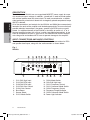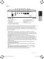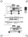
1
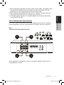
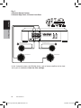
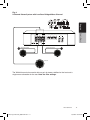
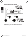
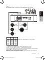
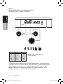
Owner’s manual & Installation manual
Mode d’emploi et manuel d’installation
Manual de instrucciones y de instalación
XN 3210
XN 3410
XN AMPLIFIERS
AMPLIFICATEURS XN
AMPLIFICADORES XN
XN3210_3410 manual_060410 R2.ind1 1
9/3/2010 8:49:17 AM
INTRODUCTION
English
The Clarion XN3210 is a full-featured, two-channel amplifier incorporating the
following features:
• Specially coated circuit boards that resists mold, mildew and moisture damage.
• Pulse-Width Modulated (PWM) MOSFET power supply for maximum
performance with minimal distortion.
• Remote turn-on with "soft start" muting to prevent turn-on "thump".
• Variable high-pass/low-pass electronic crossover with a 12dB per octave slope (adjustable range: 55Hz to 5.5kHz).
• Variable bass boost circuit to reinforce low frequency signals that may be lost due to subwoofer enclosure design.
• Adjustable input level controls with ground loop isolation to minimize noise and distortion.
• 2-ohm stereo stable, 4-ohm mono stable.
• Chrome-plated power, speaker and RCA connections.
• Speaker level input.
• Low profile construction with aluminum heat sink for efficient heat dissipation.
Owner’s Manual
The Clarion XN3410 is a full featured, four-channel amplifier adding the following
feature:
• Advanced circuitry design featuring bridgeable and mixed mode operation for use in various system configurations including 4, 3, or 2 channel systems.
ABOUT THE MANUAL AND WARRANTY
This manual describes the basic requirements to install the Clarion XN3210 and
XN3410 amplifiers. The installation of this amplifier can be quite complex to install.
If you do not posses the necessary knowledge and tools to perform this installation,
please contact your local Clarion Marine Audio dealer.
Keep all instructions and sales receipt for future reference and warranty information.
Warranty information can be found on page 19 of this manual.
TABLE OF CONTENTS
Description . . . . . . . . . . . . . . . . . . . . . . . . . . . . . . . . . . . . . . . . . . . . . . . .
Input Connections and Audio Controls . . . . . . . . . . . . . . . . . . . . . . . . . . .
Connections for Power and Speakers . . . . . . . . . . . . . . . . . . . . . . . . . . .
Installation . . . . . . . . . . . . . . . . . . . . . . . . . . . . . . . . . . . . . . . . . . . . . . . .
Mounting Precautions . . . . . . . . . . . . . . . . . . . . . . . . . . . . . . . . . . . . . . . .
Wiring Precautions . . . . . . . . . . . . . . . . . . . . . . . . . . . . . . . . . . . . . . . . . .
XN3410 Wiring and Applications . . . . . . . . . . . . . . . . . . . . . . . . . . . . . . .
XN3210 Wiring and Applications . . . . . . . . . . . . . . . . . . . . . . . . . . . . . . . .
Setting the Gain . . . . . . . . . . . . . . . . . . . . . . . . . . . . . . . . . . . . . . . . . . . .
Setting the Crossover . . . . . . . . . . . . . . . . . . . . . . . . . . . . . . . . . . . . . . . .
Setting the Subwoofer Bass Boost . . . . . . . . . . . . . . . . . . . . . . . . . . . . . .
Final System Check . . . . . . . . . . . . . . . . . . . . . . . . . . . . . . . . . . . . . . . . .
Troubleshooting . . . . . . . . . . . . . . . . . . . . . . . . . . . . . . . . . . . . . . . . . . . .
Product Specs . . . . . . . . . . . . . . . . . . . . . . . . . . . . . . . . . . . . . . . . . . . . .
4
4
6
8
8
8
9
14
17
17
17
18
18
19
XN3210/XN3410
XN3210_3410 manual_060410 R2.ind3 3
9/3/2010 8:49:17 AM
DESCRIPTION
English
Owner’s Manual
The XN3210 and XN3410 use an unregulated MOSFET power supply for superior sound and output wattage. In addition, a toroid-coil is used to transfer power
with minimal performance loss due to heat. To avoid unwanted noise, a doublesided conformal printed circuit board with strategically placed components keeps
AM RFI subdued.
All of the connections and controls for the XN3210 and XN3410 are conveniently
located at the ends of the amplifier and labeled appropriately. To ensure the best
possible electrical connections, the power, speaker, and RCA inputs are goldplated. An additional benefit of the XN3410 is the ability to create a 2, 3, or 4
channel amplified system with a flip of a switch (see Application section). In the
event of component failure or a short circuit, the XN3210 and XN3410 incorporate safe guards and outboard ATC fuses to prevent damage to the amplifier.
INPUT CONNECTIONS AND AUDIO CONTROLS
The front panel of the XN3410 and XN3210 contain both connections for RCA
and speaker level inputs, along with the audio controls as shown below.
Fig. 1
XN3410
2
3
4
5
CH3
CH1/2
6
BASS
BOOST
GAIN
CH1
INPUT
CH1-CH2
HIGH INPUT
+ CH1
– CH1
+ CH2
– CH2
GND
CH3/4
MAX
MAX
MIN
MIN
CH4
110
CH1-CH2 High Input
CH1/CH2 RCA Input
CH3/CH4 RCA Input
CH1/CH2 Gain Control
CH3/4 Gain Control
Bass Boost
Source Select
CH1/2 Mode Switch
MODE
CH1/2
MONO
16
CH3/4
CH1
MONO
POWER
CH3-CH4
HIGH INPUT
CH 1/2
X-OVER
4CH
CH 3/4
FREQ Hz
55
CH2
MONO
STEREO
RANGE
110
240
CH3/4
MONO
CH 3/4
X-OVER
CH3 +
CH3 –
CH4 +
CH4 –
GND
240
550
550
11
9
CH1/2
STEREO
2CH
2CH
BASS
330
1
SOURCE
SELECT
0
dB
15
CH 1/2 FREQ Hz
55
8
CH1/2
2-CH-IN
CH2
1.
2.
3.
4.
5.
6.
7.
8. 7
LPF HPF OFF
12
330
13
X1
X10
14
LPF HPF OFF
15
10
9. CH3/4 Mode Switch
10.CH3-CH4 High Input
11. CH1/2 Frequency Control
12.CH1/2 Crossover Mode Switch
13.CH3/4 Frequency Control
14.Frequency Range Multiplier
15.CH3/4 Crossover Mode Switch
16.Power Light Indicator
XN3210/XN3410
XN3210_3410 manual_060410 R2.ind4 4
9/3/2010 8:49:19 AM
XN3210
2
INPUT
GAIN
HIGH
INPUT
MIN
MAX
+ CH1
– CH1
+ CH2
– CH2
GND
3
BASS
BOOST
0
dB
15
CH1
4
5
FREQ
RANGE
FREQ Hz
55
6
X-OVER
7
9
MODE
POWER
English
1
110
240
550
330
X1
X10
LPF HPF OFF
STEREO
CH1/2
MONO
CH2
MONO
CH2
Owner’s Manual
8
1. CH1-CH2 RCA Input
2. Gain Control
3. Bass Boost
4. CH1/CH2 Frequency Control
5. Frequency Range Multiplier
6. Crossover Mode Switch
7. Output Mode Selector Switch
8. High Input
9. Power Light Indicator
The RCA connections are gold plated for optimum performance and low signal loss.
The RCA connectors are labeled CH1 (front left), CH2 (front right) [for XN3410:
CH3 (rear left), and CH4 (rear right)]. In applications where RCA signals are not
present, the speaker level output from the head unit can be used. (Use one or the
other input, not both.)
•
•
•
Gain Controls: For the XN3410, separate CH1/2 and CH3/4 gain controls allow you to set the nominal operating level of the amplifier. The amplifier's input range, 200mV to 6.0V for RCA inputs and 500mV to 13V for speaker level inputs, can accommodate input levels from virtually any head unit.
Bass Boost: The amplifier features a "high-Q" (i.e. narrow frequency band) Bass Boost circuit. It acts much like an equalizer with an adjustable gain from 0 to +15dB fixed at 45Hz. Use this feature to tune low-frequency audio response to compensate for a less than ideal subwoofer enclosure design. The added boost produces rich, full bass tones that are normally difficult to reproduce in the marine audio environment.
NOTE: Bass Boost setting should only be used for subwoofer applications.
Source Select (XN3410 only)
2CH BASS: Uses CH1/2 inputs and has output from all 4 channels with Bass Boost.
2CH: Uses CH1/2 inputs and has output from all 4 channels. The Bass Boost will work only on CH1/2 and have no effect on CH3/4.
4CH: Uses all 4 channel inputs and has output from all 4 channels. The Bass Boost will work only on CH1/2 and have no effect on CH3/4.
XN3210/XN3410
XN3210_3410 manual_060410 R2.ind5 5
9/3/2010 8:49:20 AM
English
Owner’s Manual
•
•
•
Output Mode Selector Switch: CH 1/2 and CH 3/4 (XN3410 only)
STEREO: Full left and right stereo operation.
CH1Mono / CH2 Mono: Single channel input for bridged operation. This is
especially useful in high-powered systems. (Uses CH2 and CH4 inputs.)
CH1/2 Mono / CH3/4 Mono: Allows for a stereo input to be summed into a mono output.
CH1/2 FREQ / CH3/4 FREQ (XN3410 only) The CH1/2 crossover frequencies are adjustable from 55Hz to 550Hz. While CH3/4 crossover frequencies are adjustable from 55Hz to 5500Hz (via the Frequency Range Multiplier) for a wider range of crossover points. Use this feature along with your speaker
manufacturer's recommended crossover frequencies to quickly design a more advanced system.
NOTE: If either of the Crossover Mode Switches is set to OFF, varying the
frequency control will have no effect.
CH1/2 Filter / CH3/4 Filter (XN3410 only) A filter is activated by sliding the
CH1/2 and CH3/4 filter switch to either HP = High Pass or LP = Low Pass.
CH1/2 is fully adjustable from 55-550Hz (via CH1/2 Freq) and CH3/4 is fully
adjustable from 55-5500Hz (via CH3/4 Frequency and Frequency Range Multiplier). Use this feature along with your speaker manufacture's recommended crossover frequencies to design a more advanced system.
CONNECTIONS FOR POWER AND SPEAKERS
The rear panel of the XN3410 and XN3210 contains power and speaker
connections as shown below.
Fig. 2
XN3410 1
2
3
4
5
REM
+12V
6
4 Ω BRIDGED
+
CH1
–
+
CH2
–
GND
FUSE
30A
+
CH3
–
+
CH4
30A
–
4 Ω BRIDGED
7
8
1. CH1 Speaker Output
2. CH2 Speaker Output
3. Ground
4. Remote Turn-on
5. Battery +12V Input
6. (2) - 30 Amp Fuse
7. CH3 Speaker Output
8. CH4 Speaker Output
XN3210/XN3410
XN3210_3410 manual_060410 R2.ind6 6
9/3/2010 8:49:20 AM
XN3410 - Electrical Connection
Remote Turn-On
F
U
S
E
English
4 Ω BRIDGED
+
CH1
–
+
CH2
GND
–
REM
+12V
FUSE
30A
+
CH3
–
+
CH4
30A
–
4 Ω BRIDGED
Owner’s Manual
CH4 Speaker (-)
CH1 Speaker (+)
CH1 Speaker (-)
CH4 Speaker (+)
CH2 Speaker (+)
CH3 Speaker (-)
CH2 Speaker (-)
CH3 Speaker (+)
Fig. 3
XN3210
1
2
3
4 Ω BRIDGED
+
L
–
+
GND
R
4
5
REM
+12V
6
FUSE
40A
–
1. Left Speaker Output
2. Right Speaker Output
3. Ground
4. Remote Turn-on
5. Battery
6. 40 Amp Fuse
XN3210 - Electrical Connection
Remote Turn-On
4 Ω BRIDGED
+
Left Speaker (-)
Left Speaker (+)
L
–
+
GND
R
REM
–
F
U
S
E
+12V
FUSE
40A
Right Speaker (-)
Right Speaker (+)
XN3210/XN3410
XN3210_3410 manual_060410 R2.ind7 7
9/3/2010 8:49:23 AM
INSTALLATION
This section suggests Mounting and Wiring Precautions for installing the Clarion
XN3210 and/or XN3410 amplifier(s). If you do not posses the necessary tools and
installation experience, do not attempt to install these amplifiers. Instead,
contact your local Clarion Marine Audio dealer to perform the installation.
English
MOUNTING PRECAUTIONS
Owner’s Manual
Prior to mounting the amplifier, make sure it is safe to mount the amplifier in that
location. Failure to do so can result in serious damage to the boat. In addition,
stainless steel hardware should be used to mount the amplifier and additional
accessories. When possible, use a nut and bolt with a lock washer to secure the
amplifier. Extra care and attention is necessary in marine installations due to the
uncertainty of water conditions.
Additional precautions and suggestions:
1. For the most efficient cooling, mount the amplifier so cool air runs along the length of the heat sink, rather than across them. To increase air movement and circulation, a cooling fan can be installed.
2. Mount the amplifier on a rigid surface; avoid mounting to subwoofer enclosures or areas prone to vibration.
3. Prior to drilling and holes, make sure the proposed mounting holes will not cut into the fuel tank, fuel lines, electrical wiring, or through the boat.
4. Do not mount the amplifier where it is susceptible to water.
WIRING PRECAUTIONS
Read all of the wiring precautions prior to making any connections. If you are
unsure and/or don't have the necessary installation hardware, contact your local
Clarion Marine Audio dealer to perform the installation.
1. Before you begin the installation, make sure the source unit Power switch is in the OFF position.
2. Disconnect the negative (-) lead of the battery (or batteries) before making any power connections.
3. When making connections, be sure that each connection is clean and secure. Insulate final connections with electrical tape or shrink tubing. Failure to do so may damage your equipment.
4. A good ground is critical for the performance of the amplifier. A ground wire should be run directly from the battery to the amplifier. Use black insulated
10-gauge or larger wire for the amplifier's ground (-) power lead.
5. Add an additional fuse holder and fuse at the positive (+) terminal of the battery. The fuse rating should equal the total current consumption at full output of the amplifier(s). Use red insulated 10-gauge or larger wire for the amplifier's positive (+) power lead. Do not install the fuse until the complete installation has been
performed.
6. When replacing the amplifier's fuse, always use one having the same amperage rating. Substituting a higher rated fuse or a slow-blow type can result in serious damage to the amplifier.
XN3210/XN3410
XN3210_3410 manual_060410 R2.ind8 8
9/3/2010 8:49:23 AM
English
7.When creating passage holes for power cables, RCA's cables, and speaker wires, use grommets to eliminate any sharp edges created during drilling. This will
protect the wire from being nicked and causing a short circuit.
8. Extra cable can cause signal loss and act as an "antenna" for noise. Use only high-quality RCA cables that are no longer than necessary.
9. In multiple amplifier systems, it is recommended to use a relay on the remote turn-on lead of the radio.
XN3410 WIRING AND APPLICATIONS
Owner’s Manual
The Clarion XN3410 4-channel marine audio amplifier can be used in a variety of
system applications. Here are some examples to help plan your own installation.
Fig. 4
4-Channel Full Range Stereo System
CH1 Speaker
CH2 Speaker
4 Ω BRIDGED
+
CH1
–
+
CH2
–
GND
REM
+12V
FUSE
30A
+
CH3
–
+
CH4
30A
–
4 Ω BRIDGED
CH3 Speaker
CH4 Speaker
In this application, the XN3410 is used as a 4-channel amplifier to drive four full
range speakers in stereo.
XN3210/XN3410
XN3210_3410 manual_060410 R2.ind9 9
9/3/2010 8:49:24 AM
Fig. 5
4-Channel Stereo System,
2-Channel High-Pass, 2-Channel Low-Pass
English
Owner’s Manual
4 Ω BRIDGED
+
CH1
–
+
CH2
–
GND
REM
+12V
FUSE
30A
+
CH3
–
+
CH4
30A
–
4 Ω BRIDGED
CH3 Speaker System
CH1 Subwoofer
CH4 Speaker System
CH2 Subwoofer
In this 4-channel system, the XN3410 drives a pair of stereo satellites for the front
and a pair of subwoofers. Note the filter settings.
10
XN3210/XN3410
XN3210_3410 manual_060410 R2.ind10 10
9/3/2010 8:49:25 AM
Fig. 6
2-Channel Stereo System with Low-Pass Bridged Mono Channel
English
Owner’s Manual
4 Ω BRIDGED
+
CH1
–
+
CH2
GND
–
REM
+12V
FUSE
30A
+
CH3
–
+
CH4
30A
–
4 Ω BRIDGED
CH3 Speaker System
CH4 Speaker System
Subwoofer
The XN3410 can also be used to drive a pair of stereo satellites for the front and a
single mono subwoofer for the rear. Note the filter settings.
XN3210/XN3410
XN3210_3410 manual_060410 R2.ind11 11
11
9/3/2010 8:49:26 AM
Fig. 7
2-Channel High Power System (Satellite or Subwoofer)
English
Owner’s Manual
4 Ω BRIDGED
+
CH1
–
+
CH2
–
GND
REM
+12V
FUSE
30A
+
CH3
–
+
CH4
30A
–
4 Ω BRIDGED
Bridged CH1/CH2
Speaker System
Bridged CH3/CH4
Speaker System
OR
Bridged Left Subwoofer
Bridged Right Subwoofer
The XN3410 can be set up as a 2-channel high power amplifier to drive a pair of
satellites (or subwoofers)
12
XN3210/XN3410
XN3210_3410 manual_060410 R2.ind12 12
9/3/2010 8:49:27 AM
Fig. 8
Mixed Mode System On CH3/CH4, Full Range Speakers On CH1/CH2
English
4 Ω BRIDGED
CH1
–
+
CH2
GND
–
REM
+12V
Owner’s Manual
+
FUSE
30A
+
CH3
–
+
CH4
30A
–
4 Ω BRIDGED
CH3 Speaker
CH4 Speaker
C
C
CH1
Speaker
L
Subwoofer
CH2
Speaker
FREQ (Hz)
L (mH)
C ( F)
80
100
125
150
200
8.0
6.4
5.1
4.2
3.2
497
398
318
265
199
NOTE: Chart values based on 4 Ohm speakers.
The amplifier can be configured for a mixed-mode operation on either
channels 1/2 or 3/4 amplifier sections. The table provides component
values to create a 6dB per octave crossover at specified frequencies. Use components
that have a + 5% tolerance and capacitors rated at 100V.
NOTE: Choose the same frequency for both LP and HP crossovers. Do not overlap
frequencies, as this may damage the amplifier.
XN3210/XN3410
XN3210_3410 manual_060410 R2.ind13 13
13
9/3/2010 8:49:28 AM
XN3210 WIRING AND APPLICATIONS
The Clarion XN3210 2-channel marine audio amplifier can be used in a variety of system applications. Here are some examples to help plan your own installation.
English
Fig. 9
Bridged - Mono Subwoofer System
Owner’s Manual
4 Ω BRIDGED
+
L
–
+
GND
R
–
REM
+12V
FUSE
40A
Set X-Over Mode to LPF and adjust
FREQ to speaker specifications.
Subwoofer 4 Ohms
In this application the amplifier is bridged for mono operation to drive a subwoofer.
Note the filter settings.
14
XN3210/XN3410
XN3210_3410 manual_060410 R2.ind14 14
9/3/2010 8:49:29 AM
Fig. 10
2-Channel Full-Range, Satellite, or Subwoofer Stereo System
(Set INPUT SELECT Switch to STEREO)
L
–
+
GND
R
REM
+12V
–
English
4 Ω BRIDGED
+
FUSE
40A
Owner’s Manual
Left Full Range Speaker
Right Full Range Speaker
Set X-Over Mode as
shown.
Left Component
Speaker System
Right Component
Speaker System
Set X-Over Mode
as shown.
Adjust FREQ to speaker
specifications.
Left Subwoofer
Right Subwoofer
Set X-Over Mode as
shown.
Adjust FREQ to speaker
specifications.
In this application, the amplifier is used in stereo and drives two full-range (or
satellite or subwoofer) speakers.
Note the filter settings.
XN3210/XN3410
XN3210_3410 manual_060410 R2.ind15 15
15
9/3/2010 8:49:30 AM
Fig. 11
Mixed-Mode Satellite and Subwoofer System
(Set INPUT SELECT Switch to STEREO)
English
4 Ω BRIDGED
+
L
–
+
GND
R
REM
+12V
–
FUSE
40A
Owner’s Manual
Left Speaker
Right Speaker
C
C
L
Subwoofer 4 Ohms
FREQ (Hz)
80
100
125
150
200
L (mH)
8.0
6.4
5.1
4.2
3.2
C (µF)
497
398
318
265
199
NOTE: Chart values based on
4 Ohm speakers.
The amplifier can be configured for a mixed-mode operation. The table provides
component values to create a 6dB per octave crossover at specified frequencies.
Use components that have a + 5% tolerance and capacitors rated at 100V.
NOTE: Choose the same frequency for both LP and HP crossovers. Do not
overlap frequencies, as this may damage the amplifier.
16
XN3210/XN3410
XN3210_3410 manual_060410 R2.ind16 16
9/3/2010 8:49:30 AM
SETTING THE GAIN
After completing the installation, follow these steps to set the Gain Control and
then perform the Final System Check.
1. Turn the Gain Control all the way counter-clockwise.
English
2. Turn the ON/OFF Switch on the source units to the ON position. Set all Tone or Equalization Controls to "flat" positions and turn Loudness off.
Owner’s Manual
3. Play a CD, set the Volume Control at 75% of full level.
NOTE: If the system uses an equalizer, set its frequency controls to "flat"
positions.
4. Slowly increase the Gain Control. Stop when you hear a slight distortion of audio.
SETTING THE CROSSOVER
The Clarion XN3210 and XN3410 feature fully adjustable high and low pass
crossovers. To set the crossover, follow these steps.
1. Using the X-Over Mode Switch, select the desired mode: LP for Low Pass, HP for High Pass or OFF for Full Range.
2. Using the Freq (Hz) Selection Control, select the desired frequency. If the desired frequency exceeds the range of the Freq (Hz) Selection Control, press the Crossover Frequency Multiplier Switch to increase the value by a multiplier
of 10.
• For example, 55Hz x 10 = 550Hz or 550Hz x 10 = 5.5kHz.
3. Repeat steps 1 and 2 for both the CH1/CH2 and CH3/CH4 crossovers on the XN3410.
SETTING THE SUBWOOFER BASS BOOST
1. Initially set the Bass Boost control to its full left position (i.e. 0dB).
2. Listen to a variety of music styles (e.g. Rock, Rap, etc.) and slowly increase
the Bass Boost control until a noticeable increase in low bass response is
perceived.
3. Slowly adjust the Bass Boost control (up or down) to realize the best bass
response.
CAUTION: If you hear a "pop" (due to speaker over-excursion), lower the
Bass Boost to prevent speaker damage. If the system sounds muddy and
distorted (due to amplifier clipping), lower Bass Boost to avoid shutdown from
overheating.
XN3210/XN3410
XN3210_3410 manual_060410 R2.ind17 17
17
9/3/2010 8:49:31 AM
FINAL SYSTEM CHECK
English
1. Turn on the source unit. After a two-second delay, slowly increase the Volume Control and listen to the audio. If you hear any noise, static, distortion or no sound at all, check the connections and refer to the Troubleshooting section. Depending on your system design, the levels may become quite loud even at low Volume Control settings. Until you get an "audio feel" of the system's power, use care when adjusting controls.
Owner’s Manual
2. Turn the Balance Controls to their extreme positions and listen to the results.
Audio imaging should match control settings (audio from the left speaker when
balance is left).
3. Increase the volume and verify that the amplifier reproduces audio (at full
frequencies) without distortion. If you hear distortion, check the connections and
verify that the Gain Control is set correctly. Another possibility is damaged
speakers or under-powered speakers. Refer to the Troubleshooting section for additional help.
TROUBLESHOOTING
Problem
No Audio.
Solution
Low or no remote turn-on voltage. Check remote connections at amplifier and
source unit.
Blown amplifier fuse. Replace with new fast-blow fuse (same rating).
Power wires not connected. Check battery and ground wiring at amplifier;
also check battery connections.
Speaker leads shorted. Check speaker continuity to ground, it should not show
a common ground.
Speakers not connected or are blown. Check speaker connections at amplifier,
measure coil impedance.
Problem
Audio cycles on and off.
Solution
Thermal protection circuits are shutting amplifier off. Check location for
adequate ventilation; consult an authorized Clarion dealer.
18
XN3210/XN3410
XN3210_3410 manual_060410 R2.ind18 18
9/3/2010 8:49:31 AM
Problem
Distorted audio.
Solution
Gain is not set properly, or damaged speaker cones. Review Setting Gain;
inspect each speaker cone for signs of damage (i.e. frozen cone, burning smell,
etc.)
English
Problem
Audio lacks punch.
Owner’s Manual
Solution
Speakers wired incorrectly, which causes cancellation of bass frequencies.
Check polarity of wires from amplifier to each speaker as defined by the
system design.
Problem
Amplifier fuse keeps blowing.
Solution
Incorrect wiring or short circuit. Review Installation and check all wiring
connections.
Problem
Whining or ticking noise in the audio with engine on.
Solution
Amplifier is picking up alternator noise or radiated noise. Turn down input
gain; move audio cables away from power wires. Check power and ground
connections on amplifier; install an in-line noise filter on source unit's power
wire; check alternator and/or voltage regulator; test for weak battery or add
water to battery.
PRODUCT SPECS
MODEL
XN3410
Frequency Response
20Hz ~ 20kHz
Signal To Noise Ratio
>97db
THD
.10% all channels driven
Input Sensitivity
Low Level
200mV ~ 6.0V
Input Sensitivity
Speaker Level
500mV ~ 13V
Max. Power Output
720W (180W x4)
Cont. Power Output
360W (90W x4) @ 1.0% THD
2-Ohm Stereo Output
165W x 4 @ 1.0% THD
Bridged Power
330W x 2 @ 1.0% THD
Dimensions
2-9/16" H x 9" W x 17-3/4" L
Current Consumption
output @ max power
58A @ 720 Watts
XN3210
20Hz ~ 20kHz
>95db
.10% all channels driven
200mV ~ 6.0V
500mV ~ 13V
360W (180W x2)
180W (90W x2) @ 1.0% THD
150W x 2 @ 1.0% THD
250W x 1 @ 1.0% THD
2-9/16" H x 9" W x 13" L
29A @ 382 Watts
XN3210/XN3410
XN3210_3410 manual_060410 R2.ind19 19
19
9/3/2010 8:49:31 AM