1
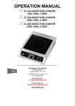
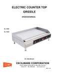
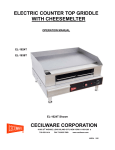
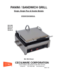
ELECTRIC COUNTER TOP CONVEYOR TOASTER OPERATION MANUAL CT-250 CT-500 CT-750 CT-500 Shown CECILWARE CORPORATION th 43-05 20 AVENUE, LONG ISLAND CITY, NEW YORK 11105-1295 718-932-1414 FAX 718-932-7860 ■ www.cecilware.com NN54A 5/05 TABLE OF CONTENTS Introduction ................................................................................. page 2 Packaging .................................................................................... page 2 Installation ................................................................................... page 3-4 Operation ..................................................................................... page 4-5 Cleaning, Care and Maintenance ............................................... page 5 Safety ........................................................................................... page 5-6 Trouble shooting ......................................................................... page 6-7 Compliance .................................................................................. page 7 Electrical Diagram ....................................................................... page 7 Explosion View ............................................................................ page 8 Spare Part List ............................................................................. page 9 Specifications .............................................................................. page 10 1 Introduction Congratulations on the purchase of your Cecilware Conveyor Toaster. Please take time to carefully read through this manual to ensure the machine is operated and maintained properly. This will enable the best possible performance from this product for many years. Cecilware will not accept liability for the following if: *The instructions in this manual have not been followed correctly. *Non-authorized personnel have tampered with the machine. *Non-original spare parts are used. *The machine has not been handled and cleaned correctly. Packaging Cecilware prides itself on quality and service, ensuring that at the time of packing all products is supplied fully functioning and free of damage. Provided in this package are the following: * * * * * * * Conveyor Toaster Crumb Tray Feeder Rack Return Chute Pass through Chute Feet (4) Manual Should you find any damage that has occurred in transit, please contact your Cecilware dealer immediately? 2 Installation Remove the Cecilware Conveyor Toaster from the packaging. Be certain that all protective plastics and residues are thoroughly cleaned from its surface. Place the Cecilware Conveyor Toaster on a firm level surface. Local standards and regulations should be consulted in order to abide by standards set in relation to positioning, spacing, and ventilation. Caution: Do not position and operate near combustible materials/flammable objects. Once the Conveyor Toaster has been placed in position, ensure the front and back stainless steel trays are positioned correctly. Supply the appropriate power and connect to source. The Conveyor Toaster is now ready to turn on and operate. (For power supply, please see technical specification sheet, page 10). Your Conveyor Toaster can operate as a pass through operation or return operation. Please see diagrams below and follow the instruction for the appropriate/required method. Front Crumb Tray Close Bac Tra k Cru mb y Back Toaster Drawer If open the back crumb Tray food can If open the back crumb tray thethefood canbebeoutout from the If closetoaster the backdrawer. crumb Trat foodthe will back be out crumb from the tray front the food back If the close crumb Tray will be out from the front crumb tray 3 Operation The Cecilware Conveyor Toaster has upper and lower elements which can be used together or alternatively; the top element can be used on its own. This can provide flexibility when toasting and grilling. The Toaster has 3 functions which are controlled by the function dial on the left of the unit. See below for the listed functions Settings: Off: Power Off Full Toast: Provide Full power to both Upper and Lower elements Top Toast: Provide full power to the upper element only Standby: Energy Saver – reduce power to unit to save power whilst not in use, whilst keep the unit warmer for fast heat when required. Please see diagram below. 4 Additionally you are able to control the speed of the conveyor rotations which in turn determine the darkness/lightness of you toasted products. Adjusting the speed control in a clockwise direction will increase the speed in turn resulting in lighter toasted products. Adjusting the speed control in a anti-clockwise direction will slow the conveyor speed in turn resulting in darker toasted products Please see diagram above. Important Notice: If the malfunction lights activates, the unit is malfunctioning. Turn off or disconnect the unit from the power supply and refer to a qualified service technician. *Caution: When in operation, the Conveyor Toaster will be hot; at the entrance to the conveyor cavity. Please take extreme caution. Cleaning, Care and Maintenance Switch off the power and disconnect from the power source. The Conveyor Toaster should be cleaned after each day’s operation; however, the unit may require more frequent cleaning, depending on the volume of production. Allow the Conveyor Toaster to cool before cleaning. Remove the return chutes, feeder and crumb trays and wipe clean with a damp cloth; be sure to dry before returning them to the unit. For details cleaning these non electrical parts can be submerged and wash thoroughly if needed. The remainder of the Conveyor Toaster can be cleaned with a damp cloth using hot, soapy water. Do not immerse completely in water or use hose to clean. Warm soapy water is recommended for cleaning; prolonged use of cleaning agents may cause damage to stainless steel. Safety Cecilware Qualified Service Technician should carry out repairs if necessary. Do not remove any components or service panels on this product. 5 When cleaning, switch power off and disconnect from the outlet. If the power cord is damaged, it must be replaced by a Cecilware Recommended Qualified Service Technician in order to avoid a hazard. Allow the Conveyor Toaster to cool down after use before dismantling for cleaning; the unit will still be too hot to handle immediately after use. Trouble Shooting If your Cecilware Conveyor Toaster does not operate, please check the following before placing a service call. Conveyor Toaster CT-250, CT-500, CT-750 Problem Cause 1. Remedy Mains power supply 1. Check mains power supply. 2. Check that the unit is correctly The unit does not work; the 2. plugged in and turned on; ensure you Unit is not switched on have read the manual for both for the indicator light is not on. operations functions. 3. Dial Control or Timer 3. Call 4. Plug and lead are 4. Call damaged or qualified service agent or qualified agent or qualified agent or qualified technician. 5. Internal wiring fault indicator lights are not on. agent technician. are faulty The unit is heating but the service 1. The indicator light is 5. Call service technician. 1. Call faulty service technician. 1. Ensure that you have clearly read the 1. Incorrect operation manual, to understand the operating 2. Warm Up functions. Slow heat up or no heat up, power is on. 2. Allow 5 minutes warm up period. 3. Elements are faulty 4. Power dial is faulty 3. Call service agent or qualified agent or qualified technician. 4. Call service technician. 1. Turn the unit on and adjust function Conveyor is not rotating 1. The unit is not on or control to required setting. the function control is not 2. activated. technician. 2. Speed Control Fault 3. 3. Motor Fault technician. 4. Gear/Chain Fault 4. Call Call Call service service service technician. 6 agent or qualified agent or qualified agent or qualified Please ensure: * There is correct power supply. * The machine is plugged in correctly and power is switched on. * The timer and thermostat are in the correct position. * The elements are clear of any food waste. Note: All Cecilware products are tested prior to packing. Compliance Cecilware products have undergone strict product testing in order to comply with regulatory standards and specifications set by international, independent, and federal authorities. As testimony to such compliance, Cecilware products carry the following marks/symbols: Electrical Diagram Model: CT-250, CT-500, CT-750 The above circuit diagram has been provided to assist qualified technicians. A Recommended Qualified Service Technician should carry out repairs if needed. Do not remove any components or service panels on this product. 7 Explosion View Model: CT-250, CT-500, CT-750 8 Spare Parts List Model: CT-250, CT-500, CT-750 CT-250 Part NO. QTY 1 Return Chute 1 NA 1 NA 1 NA 2 Feet 4 08131 4 08131 4 08131 3 Fan Cover 1 08132 1 08133 1 08133 4 Base Plate 1 NA 1 NA 1 NA 5 Fan 1 08134 1 08135 1 08135 6 Motor 1 08136 1 08137 1 08137 7 Nosing 2 08138 2 08138 2 08138 8 Shaft Bracket 4 08139 4 08139 4 08139 9 Shaft Cover 4 08140 4 08140 4 08140 10 Wheel 2 08112 2 08112 2 08112 11 Chain 1 08128 1 08128 1 08128 12 Element Fixing Plate 4 08141 4 08141 4 08141 13 Conveyor Belt 1 08142 1 08143 1 08144 14 Outer Body 1 NA 1 NA 1 NA 15 Pass Through Chute 1 NA 1 NA 5 NA 16 Back Door Chute 1 NA 1 NA 1 NA 17 Plug & Lead 1 08055 1 08047 1 08047 18 Inner Top Panel 1 NA 1 NA 1 NA 19 Inner Insulation Baffle 1 NA 1 NA 1 NA 20 Top Cover 1 NA 1 NA 1 NA 21 Element Cover 1 08145 1 08146 1 08147 22 Element Assembly Plate 2 08154 2 08154 2 08154 23 Upper Element 1 08118 1 08120 1 08122 24 Lower Element 1 08119 1 08121 1 08123 25 Conveyor Drive Shaft 2 08148 2 08149 2 08150 26 Multi Function Control Switch 1 08151 1 08151 1 08151 27 Green Indicator Light 1 08152 1 08153 1 08153 28 Red Indicator Light 1 08032 1 08067 1 08067 29 Dial 2 08109 2 08109 2 08109 30 Variable Speed Controller 1 08155 1 08156 1 08156 31 Thermal Cut Out 1 08157 1 08157 1 08157 32 Feeder 1 08158 1 08159 1 08160 33 Bushing 1 08161 1 08161 1 08161 34 Conveyor Support Runner 1/L NA 1/R NA 35 Crumb tray 1 08106 1 08107 1 08108 * Resistance 1 NA 1 NA 1 NA 2 NA NA QTY CT-750 Part NO. Description 9 QTY CT-500 Part NO. No. 2 NA NA Specifications MODEL POWER Volt(V) DIMENSIONS (INCHES) (Watts) 1500 Amps(A) LXWXH 12.5 16.5 x 11.4 x 16.1 CT-250 120 CT-500 208/240 2000/2600 9.6/10.8 16.5 x 14.5 x 16.1 CT-750 208/240 2400/3200 11.5/13.3 16.5 x 18.5 x 16.1 10 CECILWARE CORPORATION th 43-05 20 AVENUE, LONG ISLAND CITY, NEW YORK 11105-1295 718-932-1414 FAX 718-932-7860 11 www.cecilware.com ■