1
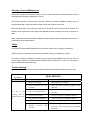
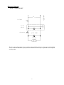
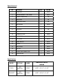
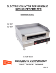
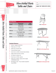
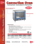
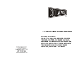
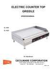
ELECTRIC COUNTER TOP
WARMER
OPERATION MANUAL
FW-25
FW-25WT
FW-25 Shown
CECILWARE CORPORATION
43-05 20th AVENUE, LONG ISLAND CITY, NEW YORK 11105-1295
718-932-1414
FAX 718-932-7860
■
www.cecilware.com
NN56A 5/05
TABLE OF CONTENTS
Introduction ............................................................... page 2
Packaging .................................................................. page 2
Installation ................................................................. page 2
Operation ................................................................... page 2
Cleaning, Care and Maintenance ............................. page 3
Safety ......................................................................... page 3
Trouble Shooting ...................................................... page 3-4
Compliance ................................................................ page 4
Electrical Diagram ..................................................... page 5
Explosion View .......................................................... page 6
Spare Parts List ......................................................... page 7
Specifications.............................................................. page 8
1
Introduction
Congratulations on the purchase of your Cecilware Counter Top Warmer. Please take a few moments
to carefully read through this manual to ensure the machine is operated and maintained properly. This
will enable the best possible performance from this product for many years.
Cecilware will not accept liability for the following if:
* The instructions in this manual have not been followed correctly.
* Non-authorized personnel have tampered with the machine.
* Non-original spare parts are used.
* The machine has not been handled and cleaned correctly.
Packaging
Cecilware prides itself on quality and service, ensuring that at the time of packing all products are
supplied fully functional and free of damage.
Provided in this package are the following:
* Warmer
* Divider Bar
* Manual
Should you find any damage as a result of freight, please contact your Cecilware dealer immediately.
Installation
Remove the Counter Top Warmer from the packaging. Be certain all protective plastics and residues
are thoroughly cleaned from its surface.
Place the Warmer on a firm level surface clear from all combustible materials.
Supply the appropriate power--(See specifications on page 6). Plug in and turn the power on.
Operation
Fill the Warmer with water to the indicated level. Do not overfill; under no circumstances, should the
food pans float. If this occurs, remove excess water. It is recommended to use fresh clean water for
each use.
To switch on, simply turn the temperature dial clockwise to the desired setting. The red light will glow
to indicate the unit is on. To turn off, simply turn the temperature dial counter clockwise to the 0
setting. It is recommended that the thermostat be set to the maximum heat of 195º F (1 full turn
clockwise) for pre-heating the warmer. An operating setting of 168º F should be sufficient once the
unit is pre-heated.
NOTE: Do not lift, move or carry the warmer when on; nor should you move the unit when it contains
food or water.
2
Cleaning, Care and Maintenance
Switch off the power and disconnect from the source. Ensure that the unit is always switched off and
unplugged while cleaning, maintaining or moving.
The Warmer should be cleaned after each day’s operation; however, additional cleaning may be
required depending on daily use. Before cleaning, allow the warmer to cool down
Empty the water basin, and clean after each use. Pans and lids can be removed to be cleaned. The
Warmer can be wiped down with a damp cloth. Do not immerse the Warmer in water or use hose to
clean.
Warm soapy water is recommended for cleaning. Cleaning agents may cause damage when used for a
prolonged period on stainless steel.
Safety
A Cecilware Recommended Qualified Service Technician should carry out repairs if necessary.
*Switch off power to and disconnect from the outlet when cleaning, maintaining or moving.
To avoid over heating or damage to the element, this unit has been installed with a Hi Limit. If the Hi
Limit is tripped, please call a Recommended Qualified Service Technician to check over the warmer,
repair if needed and reset the Hi Limit.
Trouble Shooting
If your Cecilware Warmer does not operate, please check the following before placing a service call.
Electric Counter
Top Warmer
FW-25, FW-25-WT
Problem
The unit is not
working and the
indicator light is not
on
Cause
Remedy
1. Mains power supply
1. Check mains power supply
2. Power switch has not been
turned on
2. Check the unit is correctly plugged in and
turned on
3. Fuse in the plug has blown
3. Replace the fuse in the plug with correctly
rated fuse
4. On/off switch is faulty
4. Call service agent or qualified technician
5. Plug and lead are damaged
5. Call service agent or qualified technician
6. Internal wiring fault
6. Call service agent or qualified technician
7. Thermal
activated
cut-out
has
3
7. This is a safety device that has disconnected
the power: call a service agent or qualified
technician
Problem
Cause
Remedy
The unit is heating but the
indicator light is not on
1. The indicator bulb has
blown
1. Replace the indicator light: call a
service agent or qualified technician
1.Faulty element(s)
1.Call service
technician
2.Operation of thermostat
2. Ensure that the thermostat is set
correctly, also ensure the dial is not
spinning on the thermostat and giving the
wrong reading
3.Faulty thermostat
3.
Call service agent or qualified
technician
1.No water in the pan
1. Fill the pan to the indicated level
(between Min and Max)
2. Thermostat setting
2. Ensure that the thermostat is set
correctly, and the dial is not spinning
3. Faulty element(s)
3.
Call service agent or qualified
technician
Indicator light is on but the
unit is not heating
Slow heat up
agent
or
qualified
Please ensure:
*There is correct power supply.
*The machine is plugged in correctly and power is switched on.
*The thermostat dial has been turned on.
Note: All Cecilware products are tested prior to packing.
Compliance
Cecilware products have undergone strict product testing in order to comply with regulatory standards
and specifications set by international, independent, and federal authorities.
As testimony to such compliance, Cecilware products carry the following marks/symbols:
4
Electrical Diagram
Model: FW-25, FW-25WT
120V
hi-limit
on/off
switch
thermostat
pilot light
heating
element
The above circuit diagram has been provided to assist qualified technicians. A Recommended Qualified
Service Technician should carry out repairs if needed. Do not remove any components or service panels
on this product.
5
Explosion View
FW-25
1
2
3
14
4
5
6
15
7
13
8
12
11
10
9
FW-25WT
1
2
3
14
18
4
5
17
6
7
13
8
12
11
10
9
6
15
Spare Parts List
No.
Description
QTY
Part NO
1
WATER PAN
1
08056
2
HEATING ELEMENT - 120V, 1500W
1
08057
3
ELEMENT FIXING PLATE
1
NA
4
INSULATION
1
NA
5
INSULATION COVER
1
NA
6
PAN HOLDERS
2
08058
7
MAIN BODY
1
NA
8
BASE PLATE
1
NA
9
FEET
4
08059
10
THERMOSTAT DIAL
1
08060
11
THERMOSTAT
1
08027
12
PILOT LIGHT
1
08032
13
ON/OFF SWITCH
1
08054
14
HI-LIMIT
1
08079
15
CORD & PLUG
1
08055
16
DRIP TAP
1
08089
17
FLEXIBLE HOSE CONNECTION
1
08090
18
STUFFING PLUG
1
08091
*NA = not available except by special order.
Specifications
MODEL
VOLTAGE
POWER
DIMENSIONS (INCHS)
W×D×H
FW-25
120V
50/60 HZ
1500W
14 3/8”×23 1/2”×10 1/2”
FW-25WT
120V
50/60 HZ
1500W
14 3/8”×25 3/4”×10 1/2”
7
CECILWARE CORPORATION
43-05 20th AVENUE, LONG ISLAND CITY, NEW YORK 11105-1295
718-932-1414
FAX 718-932-7860
8
www.cecilware.com
■