1
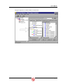
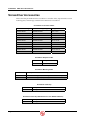
6159939020
SD25 Series Electric Screwdrivers
User’s Manual
CP Ref. / N : 6159939020
Techmotive P/N : 39-30-40409
O
DECEMBER 2005
CP Techmotive
22705 Heslip Drive
Novi, Michigan 48375 USA
24-Hour
Technical Support
Toll Free in the U.S. and Canada:
1-877-224-7377
All other countries:
(001) 248-348-6280
between 8 a.m. and 5 p.m.
Eastern Standard Time (EST)
NOTE:
Chicago Pneumatic Tool Company
(CP) in 2005 acquired and changed the name
of GSE tech-motive tool to CP Techmotive.
Product Information may be found on
www.cp.com.
NOTE:
The part number for the Visual
Supervisor (VS) software program is 46400003330 (CP part number 6150040915)
NOTE:
A variety of related technical manuals
in .pdf format may be downloaded from
www.cp.com. Click on the Technical Info
link on the left column. Select Technical
Documentation. Scroll through the list to find
the title of the product you require, and click!
®
CP Techmotive manufactures products under the CP, CP Techmotive, and tech-motive tool brand names
Information and technical diagrams in this manual are subject to change without notice. techmotive tool is a
registered trademark. Products and services referred to in this book may be either trademarks and/or registered
trademarks of their respective owners.
LIMITED WARRANTY
CP Techmotive warrants its PRODUCTS to be free from defects in materials and workmanship for the lesser of (1)
one year from the date of shipment from the manufacturing facility in Michigan, U.S.A. OR
(2) one-million cycles except for the products noted below:
250,000 cycles
CP Techmotive crowfoot, tubenut and hold & drive heads
rd
3 -party crowfoot, tubenut, hold-and-drive torque multiplier or other heads
manufacturer’s warranty
56 and 116 Series nutrunners
500,000 cycles
PRODUCTS include CP Techmotive brand fastening tools, controllers and cables, GSE brand sensors and
instruments, and anti-lock brake testing systems. Fuses and batteries are not covered under warranty.
For PRODUCTS verified as defective at CP Techmotive’s manufacturing facility, CP Techmotive shall have the
option, in its sole discretion, to repair or replace the products or components. CP Techmotive shall not be liable for
any installation charges, expenses of the Buyer for repairs or replacement, damages from delay or loss of use, or
other indirect or consequential damages of any kind. The warranty does not cover any product that has been
modified without the approval of CP Techmotive, used for a purpose other than that for which it was intended, used
in a manner inconsistent with any instructions, subjected to unusual physical stress, environmental or electrical
conditions, or whose original identification marks have been removed or altered.
Whenever the PRODUCTS are to be incorporated in a system, the design of which originated with the Buyer,
CP Techmotive only that the PRODUCTS shall be free of defects in materials and workmanship and offers no other
warranty.
In the event that a product is repaired or replaced under the terms of the warranty, the warranty period for the
repaired or replacement product shall be limited to the remaining portion of the original warranty.
Any warranty extended by the original manufacturer of peripheral equipment, such as printers, recorders, plotters,
etc., included with a CP Techmotive product or system shall be extended to the Buyer and shall be the only warranty
offered.
Transportation charges for materials shipped to the manufacturing facility for warranty repair are to be paid by the
Buyer. CP Techmotive will pay for shipping to return items repaired or replaced under warranty.
THIS LIMITED WARRANTY IS EXCLUSIVE, AND CP Techmotive MAKES NO OTHER WARRANTY OF ANY KIND
WHATSOEVER, WHETHER EXPRESSED, IMPLIED OR STATUTORY, WITH RESPECT TO THE PRODUCTS OR
PARTS MANUFACTURED BY IT, WHETHER AS TO MERCHANTABILITY, FITNESS FOR A PARTICULAR
PURPOSE OR ANY OTHER MATTER OR WARRANTY OF ANY KIND. No agent, employee or representative of
CP Techmotive has the authority to bind CP Techmotive in any affirmation, representation, or warranty concerning
the Products or parts except as stated herein.
THIS REMEDY SHALL BE THE EXCLUSIVE REMEDY AVAILABLE FOR ANY NONCONFORMITIES IN
MATERIALS OR WORKMANSHIP, OR FOR ANY DAMAGES RESULTING FROM ANY OTHER CAUSE
WHATSOEVER. CP Techmotive SHALL NOT, IN ANY EVENT, BE LIABLE FOR ANY SPECIAL, INDIRECT,
INCIDENTAL OR CONSEQUENTIAL DAMAGES OF ANY KIND, NATURE OR DESCRIPTION, WHETHER FOR
NONCONFORMITIES IN MATERIALS OR WORKMANSHIP UNDER ANY WARRANTY, IN CONTRACT, TORT,
NEGLIGENCE, STRICT LIABILITY, OR FOR ANY OTHER REASON.
CUSTOMER SATISFACTION
Please Read This!
As a valued customer, your opinion and satisfaction are important to CP Techmotive. Please let
us know what you think of our product(s).
Write the part number and serial number of the product(s) you have purchased before you begin
our brief online survey. The numbers are located on a sticker affixed to the handle of the
nutrunner or screwdriver, and exterior or interior of the controller.
Tool Label
Part Number
Serial Number
Controller Label
Part Number
Serial Number
To complete the survey:
1. Visit our website www.cp.com and click www.gsetechmotive.com
2. Click the Customer Satisfaction Survey link located below the gray buttons in the red,
left-hand frame.
3. Fill in the fields and click the appropriate choices.
4. Click the Submit to GSE tech-motive tool button
User’s Manual
Preface
Our CP techmotive SD25 Series Screwdriver is easy to operate and comes with a manual that includes
instructions to help you use it safely, make minor adjustments, and perform routine maintenance.
Who Should Use This Manual
This manual is written for the engineers and technicians, who will set up, use and maintain
CP techmotive SD25 Series screwdrivers.
How to Use This Manual
This manual introduces you to the SD25 Series Screwdriver and provides general safety and electrical
safety guidelines for using it, and covers installation, adjustment, calibration and troubleshooting of
the screwdrivers.
For the latest revision of drawings, please contact our Technical Service Department at
1-248-596-0600.
Conventions
The following conventions are used throughout this manual for the safety of personnel, equipment,
software, and data. The conventions include warnings, cautions, and notes, as follows:
WARNING!
It can be dangerous to personnel and/or machine systems,
if operating instructions are not followed. The information
appears in a box in italicized boldface type.
CAUTION!
There may be damage to equipment, and loss of software
and data, if operating instructions are not followed. The
information is indented and in italicized boldface type.
!
i
NOTE:
?
December 2005
Information that adds to your knowledge of the equipment
and/or software. The information is indented and italicized.
Page i
6159939020
SD25 Series Screwdrivers
Abbreviations
The most common abbreviations used throughout this manual are:
DCM
device control module
EEPROM electrically erasable programmable read only memory
ESD
electro-static discharge
ITI
intelligent tool interface
LED
light-emitting diode
STM
standard test method
TCM
tool control module
VS
Visual Supervisor is the setup, fastening, data collection and diagnostics software
program designed by CP techmotive
References
CS2000 Mini Controller Hardware Overview Manual (part number 39-30-38810)
CS2000/CS4000 Mini Controller and CS4100 Controller Network and Interface Supplement
(part number 30-30-40477)
Mobile Fastening System II (MFS II) User s Guide (part number 39-30-37700)
Visual Supervisor User s Guide (part number 39-30-34823)
Page ii
39-30-40409
Contents
Contents
Preface ............................................................................................................................................i
Who Should Use This Manual............................................................................................... i
How to Use This Manual ........................................................................................................ i
Conventions ............................................................................................................................ i
Abbreviations ......................................................................................................................... ii
References.............................................................................................................................. ii
SD25 Series Screwdrivers...........................................................................................................1
Electro-static Discharge (ESD) ............................................................................................2
Think Safety First! ........................................................................................................................3
General Machine Safety........................................................................................................3
Electrical Safety .....................................................................................................................5
Getting Started..............................................................................................................................6
Viewing Screwdriver Functions...........................................................................................8
Installing the Screwdriver ....................................................................................................9
Using Visual Supervisor Setup..........................................................................................10
Tightening a Fastener .........................................................................................................12
Loosening a Fastener .........................................................................................................12
Reversing the Screwdriver.................................................................................................13
Attaching a Pistol Grip Handle ..........................................................................................13
Mapping Screwdriver Functions ..............................................................................................15
Disabling the Push-to-Start Function ...............................................................................15
Enabling the Push-to-Start Function ................................................................................16
Mapping Outputs for a Single-Spindle .............................................................................18
Mapping Outputs for a Single-Spindle .............................................................................18
Troubleshooting Your Screwdriver .........................................................................................20
Maintaining Your Screwdriver ..................................................................................................22
Reading the Screwdriver Part Numbers ................................................................................23
Specifications and Parts ...........................................................................................................25
Specifications.......................................................................................................................25
Screwdriver Accessories ...................................................................................................26
December 2005
Page iii
6159939020
SD25 Series Screwdrivers
(This page is left blank intentionally.)
Page iv
39-30-40409
User’s Manual
SD25 Series Screwdrivers
Thank you for purchasing the CP techmotive SD25 Series Screwdriver, available in in-line and pistol
grip versions.
The SD25 Series In-line Screwdriver is a compact, lightweight tool of aluminum construction,
weighing one pound and measuring 9.4-in length. It provides a push-to-start output spindle and/or
trigger-start for operator preference, a forward/reverse direction button, high intensity headlights, and
torque good, high and low indicator lights. It also has a multi-purpose (auxiliary) button that can be
used for a variety of functions.
SD25 Series In-line Screwdriver
The SD25 Series Pistol Grip Screwdriver is the In-line screwdriver with an attached lightweight
aluminum pistol grip handle (part number 49-SD-10111).
Each SD25 Series Screwdriver has the capability to interface to a computer through a laptop computer
attached to the CP techmotive CS2000 Mini Controller or CS2100 Controller.
SD25 Series Pistol Grip Screwdriver
NOTE:
?
December 2005
Other accessories are available for the SD25 Series screwdrivers.
For more information, please visit our website at http://www.cp.com
then click on the Products button.
Page 1
6159939020
SD25 Series Screwdrivers
Electro-static Discharge (ESD)
The SD25 Series Screwdriver is well suited for use in electro-static discharge (ESD) safe work areas.
The screwdriver has been tested and meets the requirements of ESD Standard (S) 20.20, and also
section 5.1.3 of ESD Standard Test Methods (STM) 13.1.
Page 2
39-30-40409
User’s Manual
Think Safety First!
Working with fastening tools can be dangerous if safe and proper procedures are not followed. As
with all machinery, certain hazards can be involved with the operation of the product. Using these
tools with caution will considerably lessen the possibility of personal injury. If, however, safety
precautions are overlooked or ignored personal injury to the operator can result.
Always use common sense and exercise caution when using these tools. They can produce torque that,
unless properly compensated for, could cause personal injury. Remember, your personal safety is your
responsibility.
Only CP techmotive-qualified service technicians should perform the procedures covered in this
manual. If you are an operator or service technician, you should become familiar with the contents of
this manual before operating, servicing, or performing maintenance on any part of the fastening
system, including the SD25 Series screwdrivers. Familiarization with all components of the system
can minimize the possibility that an accident or injury might occur.
CP techmotive assumes no responsibility for personal injury or damage to equipment resulting from
misuse of these tools. After reviewing this manual you should also review all safety procedures
provided by your company and the equipment installer.
WARNING!
!
Failure to follow these rules can result in serious personal
injury.
General Machine Safety
•
FOR YOUR OWN SAFETY READ THE INSTRUCTION MANUAL THOROUGHLY
PRIOR TO OPERATING THE TOOL.
•
DO NOT WORK IN A DANGEROUS ENVIRONMENT. Do not use power tools in a
damp or wet location or explosive atmosphere, or expose them to rain, oils, or corrosive
fluids.
•
KNOW THE LOCATION OF POWER DISCONNECTS PRIOR TO OPERATING
THIS EQUIPMENT.
•
KEEP ALL ELECTRICAL PANELS CLOSED DURING OPERATION. High voltage
present inside enclosure panels can result in personal injury. Do NOT bypass or defeat
electrical safety devices. Turn the power actuator to the OFF position prior to any
servicing or maintenance of the controller.
•
OBSERVE ALL GOVERNMENT AND/OR COMPANY POWER LOCKOUT
STANDARDS.
•
NEVER OPERATE SOLENOID VALVES, LIMIT SWITCHES OR RELAYS
MANUALLY as this practice can create dangerous, unexpected machine movements.
December 2005
Page 3
6159939020
Page 4
SD25 Series Screwdrivers
•
SECURE THE TOOL. Tools that develop torque can produce hazardous torque
reactions. Always be sure that the tool is properly fixtured to absorb reaction as a
fastener is tightened. Never operate a tool capable of high torque without proper
fixturing.
•
SECURE WORK. Avoid situations where the part being fastened breaks loose and can
cause damage.
•
NEVER TOUCH OR ATTEMPT TO STOP MOVING MACHINERY OR PARTS
WITH YOUR HANDS, OTHER PARTS OF YOUR BODY, OR MAKESHIFT
DEVICES.
•
DO NOT OPERATE THE TOOL WHILE UNDER THE INFLUENCE OF ALCOHOL,
DRUGS OR MEDICATION THAT CAN IMPAIR YOUR JUDGMENT.
•
REPORT ALL UNSAFE WORKING CONDITIONS OR PRACTICES TO YOUR
SUPERVISOR AND / OR SAFETY DEPARTMENT FOR CORRECTION.
•
WEAR APPROVED SAFETY GLASSES AT ALL TIMES.
•
DO NOT WEAR JEWELRY, especially bracelets and rings, while operating the
fastening tools. Keep hands and fingers away from all rotating parts and avoid situations
where clothing can become tangled in the tool. Secure loose fitting clothing, neckties,
and long hair. Wear medical alert identification cautiously.
•
DO NOT OVERREACH. Keep proper footing and balance at all times.
•
KEEP YOUR WORK AREA CLEAN. Do not work on or near slippery floors or
surfaces. Avoid situations where the tool reacts against unexpected obstacles. Do not
operate electrical equipment while standing on a wet floor.
•
MAINTAIN TOOLS IN TOP CONDITION. Keep tools properly lubricated and clean.
If any wires become frayed or exposed, replace them immediately. Prevent dirt, grease
or contaminants from getting into the tool.
•
REDUCE THE RISK OF UNINTENTIONAL STARTING. Be careful how the tool is
left unattended. Avoid resting it on its throttle/trigger lever to prevent false starts.
•
CONTROL THE DIRECTION OF ROTATION. The reaction torque changes direction
when going from forward to reverse. Always be aware of the direction the tool will
rotate prior to using it. If the tool is not fixtured this will allow you to brace for the
proper direction of torque reaction.
•
CHECK DAMAGED PARTS. Before further use of a tool, any part of the tool that is
damaged should be carefully checked to ensure that it will operate properly and perform
its intended function. Check for alignment of moving parts, breakage of parts, mounting,
and any other conditions that may affect its operation. Never operate a tool that has
damaged or exposed wires. Never operate a tool that has any part of the powertrain,
other than the output spindle, exposed.
39-30-40409
User’s Manual
Electrical Safety
Only qualified and properly trained personnel should perform electrical/electronic
troubleshooting and repair. Consider the following electrical system safety guidelines:
•
Before you troubleshoot or service a fastening system station, be sure you have an up-todate and appropriate set of electrical drawings for that station.
•
Remove metal items, such as rings, metal necklaces, wristwatches and jewelry, as these
can create electrical hazards. Wear medical alert identification cautiously.
•
Wear safety glasses, but avoid wearing those that have metal rims or metal side shields.
•
It may be necessary to troubleshoot equipment while the power is ON. ONLY qualified,
trained personnel should do this. During these instances, open only the panels, doors, or
covers that need to be opened. Know the voltage present at all points before you begin
troubleshooting.
•
Use properly insulated tools when working on electrical equipment to reduce the
possibility of shock. Make sure the insulation is adequate to safeguard against the high
voltages present.
•
If you must work on the electrical system, make sure the Ground Fault Circuit
Interrupter (GFCI) is in the OFF position, or remove the plug from the AC outlet, or turn
off the circuit breaker.
•
Do not attempt to modify or repair the machine without the approval of the proper
authorities.
•
Use approved fuse pullers when changing fuses.
•
Never use jumper wires or fuse substitutes to replace specified fuses.
•
Always use fuses of a capacity smaller than or equal to the safe capacity of the line or
the equipment it serves.
•
Before you work on any circuit, check it with an appropriate testing device to be sure
voltage is not present.
•
Install temporary wiring as safely as possible and replace it with permanent wiring as
soon as possible. Install grounding wherever it is needed in the final installation. If
modifications are made to the system wiring, drawings must be revised to illustrate this
change.
•
Know how to deal with electrical fires properly. Keep carbon dioxide and powder
extinguishers handy.
December 2005
Page 5
6159939020
SD25 Series Screwdrivers
(This page is left blank intentionally)
Page 6
39-30-40409
User’s Manual
Getting Started
All SD25 Series handheld screwdrivers have the following features to provide torque information
right at your fingertips:
•
Programmable multi-purpose pushbutton for Cycle Complete, multi-parameter set selection, Data
Send, etc.
•
Forward / reverse direction button
•
Multi-color light-emitting diode (LED) illumination ring that indicates acceptable, high and low
torque/angle
The SD25 Series Screwdriver can identify its maximum speed and torque capacities to the controller.
However, you may need to verify that the screwdriver you have is capable of generating the torque
specified in the active parameter set displayed on the controller. If the screwdriver you are connecting
to a controller is not capable of developing the torque specified in the parameter sets it will not run at
all. You should first verify that the screwdriver operates properly.
All SD25 Series screwdrivers have internal memory inside that identifies how the screwdriver was
configured upon manufacture. Because the SD25 Series screwdrivers are highly programmable -through both the factory settings contained in the screwdriver memory and the configuration of your
particular controller -- there are many possible combinations of screwdriver functionality.
•
If your screwdriver has a multi-purpose button installed, you may have it configured to perform
one of several functions.
The Visual Supervisor (VS)-based controller (CS2000 Mini Controller connected to a laptop
computer) allows you to look at all of the factory or configured settings inside the screwdriver. VS
also allows you to change the software selectable Inputs and Outputs, change torque settings, add
parameters, enable and define the function of all switches on the screwdriver. To use the VS setup
program, open it on the laptop computer connected to the CS2000 Mini Controller. Then click on the
tool icon in the menu tree on the left side of the screen. Refer to Using Visual Supervisor Setup on
page 9 for further details.
If you have any questions about the functionality of your screwdriver, contact your sales agent or the
CP techmotive Technical Service Department for assistance.
December 2005
Page 7
6159939020
SD25 Series Screwdrivers
Viewing Screwdriver Functions
Before you operate your SD25 Series screwdriver, become familiar its functionality:
•
The factory sets the functions of the screwdriver and the
position of the buttons/lever in relationship to the head. Each
function can be re-assigned to a different button or switch using
VS.
Throttle/trigger lever or the push-to-start function starts and stops the screwdriver
•
Forward/reverse switch runs the screwdriver in clockwise or counterclockwise direction
•
LED illumination ring indicates acceptable, high and low torque/angle
•
Headlights illuminate the fastening area
NOTE:
?
These are shown in the diagram below.
Multi-purpose (auxiliary) button
Forward/reverse switch
LED illumination ring
Throttle/trigger lever
Headlight
Push-to-start
Customer supplied bits
NOTE:
?
Page 8
Some screwdrivers, such as those designated for fixtured
remote usage, do not have a throttle/trigger lever, a
forward/reverse switch, or a multi-purpose button.
39-30-40409
User’s Manual
Installing the Screwdriver
Use the following procedure to install SD25 Series screwdrivers to the CS2000 Mini Controller.
Installing the Screwdriver
1. Identify the slot on the screwdriver connector into which the screwdriver cable
plugs.
2. Align the red dot on the grip of the screwdriver cable connector to the slot on the
screwdriver connector.
Grip
Screwdriver-tocontroller cable
Slot into screwdriver
connector
Red dot
3. Insert the screwdriver cable connector into the slot on the screwdriver connector
and push firmly. There is a click when the cable is correctly inserted.
NOTE:
?
To remove the cable from the screwdriver, slide the grip on the
screwdriver cable connector away from the screwdriver and at
the same time firmly pull the screwdriver and cable connector
apart.
4. Connect the large end of the screwdriver cable to the controller.
5. Turn on power to the controller.
You will see messages on the controller display during initialization, and the screwdriver
lights will flash momentarily.
If the screwdriver lights continue to flash, read the scrolling message on the controller
display. Typically, this will read “Invalid Parameter Set X.” Fix the parameter set in the
controller via VS.
To fix the invalid parameter set:
•
Click on the Parameter Set that displays a red and black
next to it and click on
. Correct the value that is highlighted in red. Refer
the tab that also displays the
to the Visual Supervisor User’s Guide (part number 39-30-34823) for details.
If the parameter set does not need to be corrected, and a message other than “TRQ=” or
“ANG=” continues to scroll across the controller display, it is likely to be a message
indicating a data error or an operational problem. If a data error or operational problem
occurs, refer to Troubleshooting Your Screwdriver on page 19.
December 2005
Page 9
6159939020
SD25 Series Screwdrivers
6. Become familiar with how the screwdriver operates and feels.
Press the throttle/trigger lever and cycle the screwdriver in the air (not on a fastener).
Press the forward/reverse button, then press the throttle/trigger lever and watch the
output drive change direction.
OR
Press the throttle/trigger lever to enable the cycle, position the screwdriver on a fastener
and push down to start the cycle. Press the forward/reverse button, then press the
throttle/trigger lever and push down to start the cycle again and watch the fastener turn
in the opposite direction.
Using Visual Supervisor Setup
The information that appears under the General Information tab for the selected screwdriver is
displayed when a screwdriver is attached to the controller. The electrically erasable programmable
read only memory (EEPROM) chip inside the screwdriver transmits data to the analog intelligent tool
interface (ITI) board inside the controller.
If there is no screwdriver attached, the General Information tab, the User Information tab, and all
parameter set and sequence tabs are unavailable.
The values on the General Information tab vary with the attached screwdriver.
Page 10
39-30-40409
User’s Manual
In the following table, all of the left column fields are defined in the order they appear on your screen,
followed by all the second column fields.
1st Column Field
Definition
Model Number
CP techmotive part number for the screwdriver.
Build Date
The date the screwdriver was manufactured.
Serial Number
Alphanumeric serial number of the screwdriver.
Minimum Torque
Minimum usable torque value (in Nm) for the screwdriver. The controller reads this
information from the screwdriver and prevents you from using it on any application
where the target torque is BELOW this value.
Maximum Torque
Maximum usable torque value (in Nm) for the screwdriver. The controller reads
this information from the screwdriver and prevents you from using it on any
application where the target torque is ABOVE the maximum usable torque value
of the screwdriver.
Minimum Speed
Minimum usable speed in revolutions per minute (RPM) of the screwdriver.
Maximum Speed
Maximum free speed value (in RPM) of the screwdriver.
Calibration Torque
The torque calibration value (in Nm) of the screwdriver.
Calibration Counts
The analog-to-digital reading (in A to D counts) that the controller reads from the
screwdriver when the shunt calibration circuit in the screwdriver is activated.
Angle Counts/Rev
The angle scaling factor (in counts per revolution) for the screwdriver.
Last Calibration
The date the screwdriver was last calibrated.
Last Repair
The date the screwdriver was manufactured or last repaired.
2nd Column Field
Definition
Opposite Rotation
When checked, indicates the screwdriver is an opposite rotation screwdriver: for a
right-handed fastener torque cycle, the motor is run in the reverse direction, and
the torque and angle signals are negative going. When unchecked, indicates the
screwdriver is a standard rotation screwdriver: for a right-handed fastener torque
cycle, the screwdriver motor is run in the forward direction, and the torque and
angle signals are positive-going.
Left-Hand Tightening
Capable
(Also known as Bi-Directional Tightening Capable.) When checked, indicates the
screwdriver has been modified for use in left-hand fastening applications (for
example, reverse torque cycles, such as tightening a left-hand threaded fastener).
Fixtured Tool
When checked, indicates the screwdriver is designed for fixtured applications and
has no on-board controls for cycle start or direction.
Intelligent Wrench
When checked, indicates the tool is not a screwdriver, but an intelligent hand
torque wrench.
Auto Retract
When checked, indicates that the tool is a tubenut tool and the output socket must
be retracted to the open position when the tool trigger is released. This option
does not apply to screwdrivers.
Retract Shutoff Torque
When Auto Retract is checked, defines the shutoff torque setting (in engineering
units) for tubenut tools. This option does not apply to screwdrivers.
Retract Speed
When Auto Retract is checked, defines the speed setting (in RPM) for tubenut
tools. This option does not apply to screwdrivers.
Has a display
When checked, indicates the attached tool has a digital display. This option does
not apply to screwdrivers.
December 2005
Page 11
6159939020
SD25 Series Screwdrivers
2nd Column Field
Definition (continued from previous page)
Has auxiliary pushbutton
When checked, indicates that a screwdriver with multi-purpose (auxiliary)
pushbutton is attached.
Locked Rotor Count
The total number of locked rotor faults the screwdriver has had.
Overtemperature Count
The total number of motor overheating faults the screwdriver has had. Such faults
occur when the winding temperature is higher than 125 degrees Celsius.
Tightening a Fastener
For most fastening operations, make sure the screwdriver turns clockwise when running forward. For
left-hand fastening capable screwdrivers, make sure the screwdriver turns counterclockwise when
running forward.
Once the screwdriver is positioned on a part, you begin the rundown (cycle start) by:
•
Pressing the trigger lever on handheld screwdrivers that have the push-to-start function disabled
OR
•
Pressing the trigger lever on handheld screwdrivers that have the push-to-start function enabled,
then pushing down firmly on the screwdriver
OR
•
Asserting (activating) the remote start input on fixtured screwdrivers
The cycle start signal must remain active in order to complete the rundown. If the signal is interrupted
- if you release the trigger lever, for example - the screwdriver stops immediately.
When the rundown is complete, you can see the status of the rundown by:
•
The illumination of the LEDs on the screwdriver - green for acceptable torque/angle, yellow for
low torque/angle, and red for high torque/angle
•
The controller display
•
VS software displays the final torque/angle
NOTE:
?
For details of asserting (activating) remote inputs and reading
the controller display, refer to the appropriate controller manual.
Loosening a Fastener
For unfastening operations, make sure screwdriver turns counterclockwise when running forward. For
left-hand fastening capable screwdrivers, make sure the screwdriver turns clockwise when running
forward.
Once the screwdriver is positioned on a part, you begin the rundown (cycle start) by:
•
Pressing the trigger lever on handheld screwdrivers
•
Asserting (activating) the remote reverse direction input on fixtured screwdrivers
The cycle start signal must remain active in order to complete the rundown. If the signal is interrupted
- if you release the trigger lever, for example - the screwdriver stops immediately.
Page 12
39-30-40409
User’s Manual
Reversing the Screwdriver
When the screwdriver is put into reverse, by sliding the forward/reverse switch into the reverse setting
or remotely activating the FWD/REV input, the screwdriver turns in the opposite direction to the
normal fastening direction. Reverse is indicated by the yellow, green and red LEDs chasing in a
counterclockwise direction while the headlights remain lit. For most fastening operations, the
screwdriver turns in a counterclockwise direction when in reverse, but for left-hand fastening
applications it is clockwise.
Attaching a Pistol Grip Handle
The diagram below shows the SD25 Series In-line screwdriver with the throttle/trigger lever and
spring removed and the Pistol Grip handle (part number 49-SD-10111) slid into place.
December 2005
Page 13
6159939020
SD25 Series Screwdrivers
Use the following procedure to attach a Pistol Grip handle (part number 49-SD-10111) to an In-line
screwdriver. Refer to Viewing Screwdriver Functions on page 7 to view an illustration of the
In-line screwdriver that may help you with this procedure.
Attaching a Pistol Grip Handle
1. Remove the screwdriver-to-controller cable, if necessary.
2. Using a 5/32-in punch, hammer out the pin that attaches the throttle/trigger lever
to the In-line screwdriver.
3. Remove the throttle/trigger lever spring. It may fall out when you remove the
throttle/trigger lever so be prepared to catch it.
NOTE:
?
Put the throttle/trigger lever and spring into a safe place. If, in
the future, you remove the handle attachment, you will need
the throttle/trigger lever and spring to convert the screwdriver
back to the In-line model.
4. Carefully slide the In-line screwdriver into the handle attachment with the
forward/reverse and multi-purpose (auxiliary) buttons positioned on the top.
5. Position the handle on the bottom of the screwdriver, on the side of the
screwdriver opposite to the forward/reverse and multi-purpose (auxiliary) buttons.
6. Slide the pin back into the handle attachment.
You will need to hammer it carefully back into place. Make sure the screwdriver does not
rotate or move in relation to the position of the handle during this process.
7. Using a 5/32-in Allen wrench, tighten the fastener on the handle attachment until it
is secure.
You are now ready to use your Pistol Grip screwdriver.
Page 14
39-30-40409
User’s Manual
Mapping Screwdriver Functions
This section describes how VS is used to map screwdriver functions to the buttons and switches on
the screwdriver. You can also use VS to change the default mapping. To do this, refer to the Visual
Supervisor User s Guide (part number 39-30-34823).
Disabling the Push-to-Start Function
Typically, to start a fastening cycle when the push-to-start function on a handheld screwdriver is
disabled:
•
Press the throttle/trigger lever to start the fastening cycle.
•
Release the throttle/trigger lever to stop the fastening cycle.
December 2005
Page 15
6159939020
SD25 Series Screwdrivers
The screwdriver inputs are software selectable using VS. To disable the push-to-start function, assign
the Cycle On input, Cycle Enable input and the Clear Outputs input to the Trigger. The typical inputs
for a screwdriver with push-to-start function disabled are shown below.
Enabling the Push-to-Start Function
Typically, to start a fastening cycle when the push-to-start function on a handheld screwdriver is
enabled:
•
Press the throttle/trigger lever to enable the fastening cycle.
•
Push down firmly on the screwdriver to start the fastening cycle.
•
Release the throttle/trigger lever to stop the fastening cycle.
OR
•
Page 16
Release the pressure on the screwdriver to stop the fastening cycle.
39-30-40409
User’s Manual
The screwdriver inputs are software selectable using VS. To enable the push-to-start function, assign
the Cycle On input to Input 8, and assign the Cycle Enable input and Clear Outputs input to the
Trigger. The typical inputs for a screwdriver with push-to-start function enabled are shown below.
December 2005
Page 17
6159939020
SD25 Series Screwdrivers
Mapping Outputs for a Single-Spindle
Typically, the LEDs and headlights on the screwdriver work in the following way:
•
Headlights turn on while the screwdriver is running in forward or reverse.
NOTE:
?
Yellow, green and red LEDs chase each other in a
counterclockwise direction while the screwdriver is in reverse.
•
Green LEDs turn on to indicate a successful cycle completion achieving target torque/angle
within acceptable range.
•
Yellow LEDs turn on to indicate lower than acceptable torque/angle.
•
Red LEDs turn on to indicate higher than acceptable torque/angle.
The screwdriver outputs are software selectable using VS. To operate the screwdriver as a singlespindle tool, assign the Cycle Good output to Output 2, Cycle Bad output to Output 3, Output 8
(Timed Copy) to Output 7 and the Ready output to Output 8. The typical outputs for operating the
screwdriver as a single-spindle tool are shown below.
NOTE:
?
Page 18
The time delay for Output 8 (Timed Copy) can be adjusted
using the Timers tab in VS. For details, refer to the Visual
Supervisor User’s Guide (part number 39-30-34823).
39-30-40409
User’s Manual
The typical outputs for screwdriver LEDs are shown below.
December 2005
Page 19
6159939020
SD25 Series Screwdrivers
(This page is left blank intentionally)
Page 20
39-30-40409
User’s Manual
Troubleshooting Your Screwdriver
The CS2000 Mini Controller used with the screwdriver has many configurable features and
programmable parameters that control the operation of the fastening system equipment.
CP techmotive supply the VS software program that provides you with a way to change parameters
that affect operation of the controller and attached screwdriver. If you apply these features or program
the parameters improperly, erroneous data and manufacturing problems can result. Proper setup of the
controller is essential in preventing such situations.
Whenever the data seems to be in error or operational problems occur, refer to one of the following
manuals:
⇒
CS2000 Mini Controller Hardware Overview Manual (part number 39-30-38810)
⇒
CS2100 Controller Hardware Overview Manual (part number 39-30-41886)
⇒
CS2000/CS4000 Mini Controller Network and Interface Supplement (part number 39-30-40477)
⇒
CS4100/2100 Controllers Technical Reference (part number 39-30-41994)
⇒
The online help manual that is part of the VS software
December 2005
Page 21
6159939020
SD25 Series Screwdrivers
Maintaining Your Screwdriver
Generally, there is no preventive maintenance required for CP techmotive screwdrivers.
CP techmotive only recommends trained technicians to perform in-depth maintenance, such as motor,
transducer, or gearing replacement.
NOTE:
?
Page 22
For the latest assembly drawing revisions, contact our
Technical Service Department at 1-248-596-0600.
39-30-40409
User’s Manual
Reading the Screwdriver
Part Numbers
All SD25 Series Screwdrivers have an 8-digit prefix that helps you quickly identify the type of
screwdriver you are using, and a longer suffix that provides more details about the screwdriver.
Prefix example: SD25I010
SD
Screwdriver
And the suffix:
25
I
Series Type: In-line
010
Capacity lbf-in
P, L, B, or M
A
Q2, H4 or H5
PUSH-TO-START
TRIGGER LEVER
BOTH TRIGGER AND PUSH-TO-START
MOUNTED (PUSH-TO-START, NO TRIGGER LEVER, REMOTE START)
ALUMINUM HEAD
QUICK RELEASE CHUCK, 1/4-IN
HIOS CHUCK, 4 MM
HIOS CHUCK, 5 MM
December 2005
Page 23
6159939020
Page 24
SD25 Series Screwdrivers
39-30-40409
User’s Manual
Specifications and Parts
This section lists the specifications of your SD25 Series screwdrivers under typical operating
conditions and available screwdriver-to-controller cables.
Specifications
This section lists general specifications, torque and RPM ranges, and length and weight ranges for
SD25 Series screwdrivers.
General Specifications for SD25 Series Screwdrivers
Description
Specifications
Motor current
8A peak
Motor commutation
Hall-based, brushless DC motor
Screwdriver logic power
24 VDC
Screwdriver pushbuttons*
Start, direction, auxiliary, push-to-start
Screwdriver connector
High density 26-pin connector
Screwdriver Display
Three indicator / status LEDs for torque/angle
Screwdriver Headlights
Turn on when screwdriver is running in forward or reverse
Ambient operating temperature
0✘ to 60✘ C (32✘ to 140✘ F)
Relative humidity
0 to 85% R.H. (non-condensing)
* Not available on fixtured screwdrivers
Torque, RPM, Length and Weight Ranges of SD25 Series Screwdrivers
Torque Range
Screwdriver
Type
Nm
lbf-in
ozf-in
kgfcm
In-line
1.1
10
160
In-line
3.3
20
In-line
3.9
In-line
5.6
December 2005
RPM Range
Length Range
Weight Range
11.5
1700
9.4 in / 239 mm
0.91 lb / 0.41 kg
320
23.0
1100
9.4 in / 239 mm
0.91 lb / 0.41 kg
35
560
40.3
800
9.4 in / 239 mm
0.91 lb / 0.41 kg
50
800
57.6
500
9.6 in / 244 mm
1.1 lb / 0.49 kg
Page 25
6159939020
SD25 Series Screwdrivers
Screwdriver Accessories
This section lists part numbers for the screwdriver-to-controller cables, suspension bail, reaction
mounting plates, and foam grip available for the SD25 Series screwdrivers.
Screwdriver-to-Controller Cables
Part Number Straight
Part Number Right Angle
Length
299230-81050
299230-81050R
5 ft / 1.5 m
299230-81100
299230-81100R
10 ft / 3.0 m
299230-81150
299230-81150R
15 ft / 4.6 m
299230-81200
299230-81200R
20 ft / 6.1 m
299230-81250
299230-81250R
25 ft / 7.6 m
299230-81300
299230-81300R
30 ft / 9.1 m
299230-81350
299230-81350R
35 ft / 10.7 m
299230-81400
299230-81400R
40 ft / 12.2 m
299230-81450
299230-81450R
45 ft / 13.7 m
299230-81500
299230-81500R
50 ft / 15.2 m
Screwdriver Suspension Bail
Part Number
Description
49-SD-10112
Vertical Suspension Bail
Screwdriver Mounting Plates
Part Number
Description
49-SD-10121
Reaction mounting plate, double flange, for fixtured mounting
49-SD-10125
Reaction mounting plate, single flange, for close fixtured mounting
Screwdriver Foam Grip
Part Number
Description
31-80-39445
Foam grip for the SD25 Series In-line Screwdriver
Screwdriver Pistol Grip Attachment for In-line SD25 Screwdriver)
Page 26
Part Number
Description
31-SD-10111
Pistol grip for the SD25 Series In-line Screwdriver
39-30-40409
(This page is left blank intentionally)
www.cp.com
Please find your local contact at: www.cp.com
U.S. English
Printed in USA
Copyright 2005
CP Techmotive, Novi, MI, USA