1
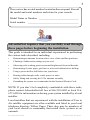
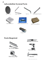
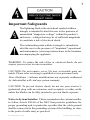
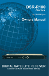
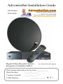
AdventistSat Installation Guide
GEOSATpro
DVR1000ci
Digital Video Recorder System
Reception of Satellite AMC4
45+ Hours Record Capacity
Dish Aiming Information for Zip Code ____________
.
Compass Azimuth
_______._______°
LNBF Rotation
_______._______°
Dish Elevation _______ _______°
+ / -
Important Installation Notice: The Federal Communications
Commission (FCC) has ruled that local government zoning or
homeowner’s associations may not prevent the installation of
satellite antennas one meter (39”) or smaller in diameter, unless
legitimate safety restrictions such as fire codes are in effect.
For more information: www.fcc.gov/cgb/satellite.html
Table of Contents
Advent V.101
Page
Parts List
4
Important Safeguards
5
Site Survey
10
Dish Assembly
14
Universal Post Mount Assembly and Install
18
Dish Aiming Angles
20
Connect Receiver and Television
22
Locate and Peak Satellite Signals
23
Grounding the System
27
Basic Operation
28
Frequently Asked Questions
29
Connection Examples
31
Accessories
32
Limited Warranty
33
Quick Install Guide for Professional Installers
34
Site Check: Satellite Elevation Finder Tool
37
Note: Save all original boxes, manuals, accessories
and packaging materials in case it is necessary to return
the merchandise. You have 30 days from the date of
delivery to return the equipment for refund or exchange to
AdventistSat.
Before unpacking or assembly of any item, review the
warranty, exchange and refund policy on page 33 of this
manual.
Please call 866-552-6882 with any questions.
Materials contained in this installation manual are the property of:
AdventistSat
8801 Washington Blvd., Suite 101
Roseville, CA 95678
www.adventistsat.com
©2006 Adventistsat.com
www.adventistsat.com
Toll Free 866-552-6882
©2006 Adventistsat.com
The receiver has a serial number located on the rear panel. Record
the model and serial numbers and retain for your records.
Model Name or Number _____________________________
Serial number
_____________________________________
AdventistSat requires that you carefully read through
these pages before beginning the installation.
This guide is intended for an individual experienced in performing
the various tasks described, including:
•
Determining an antenna location with a view of the satellites positions.
•
Climbing a ladder and working on your roof.
•
Observing safe working practices around heights and electrical hazards.
•
Determining if water pipes, gas lines or wires are hidden before drilling.
•
Using a power drill to drill holes into your house.
•
Routing cable through walls, crawl spaces or attics.
•
Safely lifting and securing the 25 lb. antenna assembly.
•
Grounding the system as recommended in the National Electric Code.
NOTE: If you don’t feel completely comfortable with these tasks,
please contact AdventistSat toll free at 866-552-6882 or local 916677-6228 for information on having your system installed by a local
installer.
Local installers that are experienced with the installation of Free to
Air satellite equipment are often available and listed in your local
telephone directory Yellow Pages. There also may be members of
your local church or community that install these systems as an
outreach.
www.adventistsat.com
Toll Free 866-552-6882
AdventistSat System Parts
Reflector (1)
LNBF ARM (1)
Installation Kit (1)
Post (1)
Satellite DVR Receiver (1)
Tripod Support Leg (2)
Dish Accessory Kit (1)
LNBF (1)
Tools Required
Phillips Screwdriver
10, 11mm Socket
Drill and Bits
Measuring Tape
Hammer
©2006 Adventistsat.com
Important Safeguards
The lightning flash with arrowhead symbol within a
triangle is intended to alert the user to the presence of
uninsulated “dangerous voltage” within the product’s
enclosure—voltage that may be of sufficient magnitude
to constitute a risk of electrical shock.
The exclamation point within a triangle is intended to
alert the user to the presence of *important* operational
and maintenance (servicing) instructions in the literature
accompanying the appliance.
WARNING: To reduce the risk of fire or electrical shock, do not
expose your receiver to rain or moisture.
Caution: Do not remove cover. No user serviceable parts are
inside. Please refer servicing to qualified service personnel only.
Note: Hardware / software modifications not expressly authorized
by AdventistSat will void any system warranty.
Caution: To prevent electric shock, do not use your receiver’s
(polarized) plug with an extension cord receptacle or other outlet
unless the blades can be fully inserted to prevent blade exposure.
Notice to System Installer: This is a reminder to the system installer
to follow Article 820-40 of the NEC that provides guidelines for
proper grounding and, in particular, specifies that the cable ground
shall be connected to the grounding system of the building, as close
to the point of cable entry as practical.
www.adventistsat.com
Toll Free 866-552-6882
Example of Antenna Grounding
NEC, ANSI/NFPA 70
CAUTION: Read all of these Instructions. Save these Instructions
for later use. Follow all Warnings and Instructions marked on the
equipment.
Read Instructions All the safety and operating instructions should
be read before the product is operated.
Retain Instructions The safety and operating instructions should be
retained for future reference.
Heed Warnings All warnings on the product and in the operating
instructions should be adhered to.
Follow Instructions Follow all operating and usage instructions.
Cleaning Unplug this product from the wall outlet before cleaning.
Do not use liquid cleaners or aerosol cleaners. Use a damp cloth for
cleaning.
Attachments Do not use attachments not recommended by the
product manufacturer as they may cause hazards.
Water and Moisture Do not use this product near water. For example,
near a bath tub, wash bowl, kitchen sink, or laundry tub; in a wet
basement, near a swimming pool, etc.
©2006 Adventistsat.com
Accessories
Do not place this product on an
unstable cart, stand, tripod, bracket, or table. The
product may fall, causing serious injury to a child or
adult, and serious damage to the product. Use only
with a suitable cart, stand, tripod, bracket, or table.
Any mounting of the product should follow the manufacturer’s
instructions, and should use a mounting accessory recommended by
the manufacturer. A product and cart combination should be moved
with care. Quick stops, excessive force, and uneven surfaces may
cause the product and cart combination to overturn.
Ventilation
Slots and openings in the cabinet are provided for
ventilation and to ensure reliable operation of the product and to
protect it from overheating. These openings must not be blocked
or covered. The openings should never be blocked by placing the
product on a bed, sofa, rug, or other similar surface. This product
should not be placed in a built-in installation such as a bookcase
or rack unless proper ventilation is provided or the manufacturer’s
instructions have been adhered to.
Power Sources This product should be operated only from the
type of power source indicated on the marking label. If you are
not sure of the type of power supply to your home, consult your
product dealer or local power company. For products intended to
operate from battery power, or other sources, refer to the operating
instructions.
Grounding or Polarization This product may be equipped with
a polarized alternating current line plug (a plug having one blade
wider than the other). This plug will fit into the power outlet only
one way. This is a safety feature. If you are unable to insert the plug
fully into the outlet, try reversing the plug. If the plug should still
fail to fit, contact your electrician to replace your obsolete outlet. Do
not defeat the safety purpose of the polarized plug.
Power Cord Protection Power supply cords should be routed so
that they are not likely to be walked on or pinched by items placed
upon or against them, paying particular attention to cords at plugs,
convenience receptacles, and the point where they exit from the
product.
www.adventistsat.com
Toll Free 866-552-6882
Outdoor Antenna Grounding When an outside antenna or cable
system is connected to the product, be sure the antenna or cable
system is grounded so as to provide some protection against voltage
surges and built-up static charges. Article 810 of the National
Electrical Code, ANSI/NFPA 70, provides information with regard
to proper grounding of the mast and supporting structure, grounding
of the lead-in wire to an antenna discharge unit, size of grounding
conductors, location of antenna discharge unit, connection
to grounding electrodes, and requirements for the grounding
electrode.
Lightning For added protection for this product during a lightning
storm, or when it is left unattended and unused for long periods
of time, unplug it from the wall outlet and disconnect the antenna
or cable system. This will prevent damage to the product due to
lightning and power line surges.
Power Lines An outside antenna system should not be located in
the vicinity of overhead power lines or other electric light or power
circuits, or where it can fall into such power lines or circuits. When
installing an outside antenna system, extreme care should be taken
to keep from touching such power lines or circuits as contact with
them might be fatal.
Overloading Do not overload wall outlets, extension cords, or
integral convenience receptacles as this can result in risk of fire or
electric shock.
Object and Liquid Entry Never push objects of any kind into
this product through openings as they may touch dangerous voltage
points or short-out parts that could result in a fire or electric shock.
Never spill liquid of any kind on the product.
Heat The product should be placed away from heat sources such as
radiators, heat registers, stoves, or any product that produces heat.
©2006 Adventistsat.com
Servicing Do not attempt to service this product yourself as
opening or removing covers may expose you to dangerous voltage
or other hazards. Refer all servicing to qualified service personnel.
Modification to the hardware or software without authorization
by AdventistSat the will result in voiding any warranty. Service
assistance may be arranged by contacting AdventistSat technical
support at 866-552-6882.
Damage Requiring Service Unplug this product from the wall
outlet and refer servicing to qualified service personnel under the
following conditions:
When the power supply cord or plug is damaged.
If liquid has been spilled, or objects have fallen into the product.
If the product has been exposed to rain or water.
If the product does not operate normally by following the operating
instructions. Adjust only those controls that are covered by the
operating instructions as an improper adjustment of other controls
may result in damage and will often require extensive work by a
qualified technician to restore the product to its normal operation.
If the product has been dropped or damaged in any way.
When the product exhibits a distinct change in performance, this
indicates a need for service.
Replacement Parts When replacement parts are required, be sure
the service technician has used replacement parts specified by the
manufacturer or have the same characteristics as the original part.
Unauthorized substitutions may result in fire, electric shock, or other
hazards.
Safety Check Upon completion of any service or repairs to this
product, ask the service technician to perform safety checks to
determine that the product is in proper operating condition.
www.adventistsat.com
Toll Free 866-552-6882
10
Site Survey
If you feel comfortable with drilling holes in the walls and/or roof
of your home, climbing ladders, attaching wires to the utility ground
according to NEC and local codes and following step-by-step
instructions, you might consider installing your
own system.
The satellite is located over 23,000 miles away
and the installation does require precise tuning
and a great deal of patience to correctly install.
Have you recently installed a light switch, ceiling
fan, basketball hoop and programmed a VCR? If
not, this project might not be a good time to hone
your mechanical and electrical skills!
Please contact AdventistSat 866-552-6882 if you would
like to schedule a basic professional installation in the US
and Canada. In Mexico call 800-727-1080.
Will a AdventistSat System work at your home? Before assembling
any equipment it is important to verify that the installation location
has a suitable area to safely and securely mount the satellite dish and
have a clear line of site to receive the satellite signal. The satellite
dish must be pointed directly at the satellite, with NO obstructions
between the two. This means NO trees and NO buildings. Satellite
signals will not pass through leaves, limbs, so consider future tree
growth, house remodeling or additions and new construction in your
area. Do not attempt to install the dish indoors!
©2006 Adventistsat.com
11
Where Is The Satellite?
Generally the dish will point towards the South, Southeast or
Southwest. The satellite is located south of Texas and Mexico
directly over the equator. That means if you live in Miami, you
must have a clear line of sight to the Southwest; if you live in San
Francisco, you must have a clear line to the Southeast.
Compass Azimuth Reading: _______________
www.adventistsat.com
Toll Free 866-552-6882
12
How High Up in the Sky is the Satellite?
Depending on where you live, the satellite will be at an elevation
angle between 30 and 60 degrees. Southern US point more toward
60 degrees; northern US point more toward 30 degrees. Northern
Canada and Hawaiian elevations can be as low
as 10 degrees, but Central American dishes will
be aimed almost straight up!
Dish Elevation Angle: ___________
Compass
Elevation Angle Finder
Using the Site Check Tools
Using the aiming coordinates located on the front cover of this
guide along with a compass and the Site Check Satellite Elevation
Finder located on the last page of this manual, locate a suitable dish
mounting position. While facing south, hold the compass level in
the palm of your hand. With the red needle pointed exactly at North,
reference the compass reading. Are there any obvious obstructions?
If the line of sight appears clear, continue to the check the elevation
angle. Sight along the top edge of the elevation angle finder with the
weighted string registering the correct elevation angle. Is the line of
sight clear with no branches, limbs or tall buildings?
Please note that the Elevation Angle Finder is only used for the site
check and cannot be used to set the elevation angle of the dish. The
elevation scale on the back of the dish is used for setting the correct
elevation angle.
©2006 Adventistsat.com
13
Dish Mounting Options
We recommend ground mounting the dish on
a 1 5/8” heavy wall galvanized post set in
cement. Attach a bolt or muffler clamp to the
bottom of the post to prevent the post from
twisting in the hardened cement. These items
are readily available at any hardware store.
Filling the post with a wet cement mixture
will provide greater rigidity. The post must
be perfectly plumb, level on all sides.
Posts standing higher than 7 feet should
be stabilized to prevent movement during
high winds. The post should be installed in
advance of the install as the cement can take Ground Post Mount
24 - 48 hours to set. Do not install the dish on a wooden 4” x 4” post
or on a tree. The grain of the wood will twist during dry and rainy
seasons causing the dish to swing off of the satellite causing reduced
or loss of signal. Take proper precautions to protect the dish from
being bumped during yard care or damaged by children at play.
Wall Mount
Roof Mount
The AdventistSat system includes a heavy duty universal wall / roof
post mount. This mount can be attached at almost any angle and
provides a stable secure mount even in high wind regions if properly
attached. If this universal post mount is used, the included tripod
legs MUST be installed. The universal post will fail under moderate
wind load if the tripod legs have not been installed to support the
larger wind load area of a 36” dish. The dish and mount are designed
to remain operational in winds up to 80+ mph and survive wind
gusts over 110+ mph.
Failure to install the tripod legs will result in a
charge back to the professional installer.
www.adventistsat.com
Toll Free 866-552-6882
14
Dish Assembly
Once a suitable dish mounting location
has been chosen it is time to set up the
dish. Use the large cardboard shipping
box as a working surface to prevent
damage to the dish components during
assembly. We recommend assembling
the dish first and then installing on the
post mount.
Important Note:
An assembled dish will not be accepted for refund.
Dish Reflector Accuracy
Before assembling the dish it is extremely important to verify that
the reflector was not warped during shipping. Failure to check for
dish warpage could lead to many frustrating hours of trying to locate
the satellite.
Bad - Warped Reflector
Good - Reflector
Find a perfectly flat surface such as a garage cement floor and lay the
reflector face down. Are the edges of the reflector laying perfectly
flat? If any area of the edge is raised by even an 1/8th of an inch
reception of the satellite signal could be affected!
It is important to check the reflector for warping before
assembly of the satellite dish.
©2006 Adventistsat.com
15
If the reflector edges are not laying
perfectly flat, pick up the dish by
the edges like a steering wheel and
quickly thrust the reflector away from
your body while holding the edges of
the dish. This action will cause the
reflector to flex and it will spring back
into the factory pressed shape. Lay the
reflector face down and observe if the
edges are now laying perfectly flat. If
not, repeat the flexing process until the
reflector edges are uniform and laying
perfectly flat against the surface.
GEOSATpro 90cm Dish Hardware
Item Quantity
Description
Size
1
6
Carriage Bolt
M6 - 12mm
2
3
4
5
2
2
12
2
Phillips Screw
Hex Nut
Hex Nut 10mm
Carriage Bolt
M4 - 16m
M4
M6
M6 - 20mm
6
7
8
1
2
2
Structural Bolt 10mm
Elevator Bolt
Washer
M6 - 60mm
M6 - 30mm
M6
A
B
C
4
1
1
Hex Flange Bolt
Hex Nut 10mm
Hex Tap Bolt
M6 - 12mm
M6
M6 - 90mm
D
1
Fastener Insert
Please contact AdventistSat at 866-552-6882 if any of these parts
are missing or damaged. Most replacement or damaged hardware
items can be found at a local hardware supply store.
www.adventistsat.com
Toll Free 866-552-6882
16
Attach the LNBF Arm to the Elevation
Bracket. Assemble the Elevation
Bracket and Post Clamp. Most
installations in the US and Canada will
use Elevation Scale A type assembly.
Mexico installations will usually use
Elevation Scale B assembly.
US and Canada
Mexico
The Post Clamp has two holes drilled. One hole is stamped with an
A and the other with a B. Assemble the Elevation Bracket to the Post
Clamp using either the hole stamped A if the Dish Elevation Angle is
between 20 - 50 degrees or the hole stamped B if the elevation angle
is 50 – 90 degrees. The dish has been
correctly assembled for Measuring the
Dish Elevation Angle using the A Scale
if an upside letter B is visible stamped on
the Post Clamp. If an upside down letter
A is visible on the Post Clamp, the dish
has been assembled to use Scale B for
measuring the Elevation Angle.
After verifying the reflector is not
warped, mount to the Elevation
Bracket.
©2006 Adventistsat.com
17
Assemble the LNBF Clamp and attach the
LNBF clamp to the LNBF arm.
LNBF Rotation Angle: _______________
Install the GEOSATpro Mini Bullet
LNBF into the LNBF Clamp. Slide the
LNBF as far away from the reflector as
possible so the tabs on the LNBF plastic
housing touch the LNBF clamp. Rotate
the LNBF in the circular clamp until the
centering line on the top of the LNBF
aligns with the LNBF Rotation specified
in the aiming coordinates.
Standing in front of the dish looking
towards the reflector, rotate the LNBF counter clockwise (left) for
a positive (+) LNBF Rotation setting and Clockwise (right) for a
negative (-) LNBF Rotation setting. The Rotation Angle is marked on
the LNBF Clamp for Zero (0) and +/- 20
degree positions. Each mark on the clamp
measures 5°. Example: If the aiming
coordinates specify a LNBF Rotation of
+13, set the pointer to a position between
+10° and +15° counter clockwise (left).
Tighten both clamp screws (2).
If the aiming coordinates specify a number
greater than +/- 20 degrees, estimate the
Example: Positive +20° additional number of degrees necessary
for setting the correct rotation angle. Example: If the Aiming
Coordinates specify a LNBF Rotation of -30, estimate and add an
additional 10° (two additional marks) and set the center pointer to
a -30° clockwise position.
www.adventistsat.com
Toll Free 866-552-6882
18
Optional: Universal Post
Mount the Universal Post Mount Foot Plate to a
wall stud or roof rafter using two 5/16th x 3” lag
bolts. Adding 5/16th x 2” lag bolts on the outer
edges will increase stability.
To prevent water leakage, use the
included silicone sealant or other
waterproofing product on all wall
or roof penetrations.
The Universal Post Mount can be assembled for
roof or wall type installations. The post has slots
for attaching to the Foot Plate on both ends of
the tube. This allows the dish to be mounted with
either a higher reach above a roof (as pictured)
or outward reach away from a wall when using
the slots on the opposite end of the post.
Level and Secure Post
Insert the Bubble Level into the top of the post. Be sure that it is
seated level with the top edge of the post.
The unique slots in the post tube
allows the post to be leveled in almost
any installation position. Center the
bubble in the level then tighten the
4 flange bolts to secure the post. It is
very important to make sure that the
post is perfectly plumb (level on all
sides).
©2006 Adventistsat.com
19
If the post is not exactly plumb, the elevation scale will not be
accurate and it will be very difficult to locate the satellites and
properly tune the dish for reliable reception.
Not Level Level
The most critical step to providing a
stable mounting platform for the dish
is the installation of the Tripod Support
Legs. If the lag bolts cannot be secured
directly into a stud or rafter, the legs
should be secured into plywood sheeting
with either a backing a toggle bolt or to
a 2 x 4” that is lag bolted between the
rafters or studs.
Remember to use silicone or other sealant on any roof or wall
penetration. The legs are required to support the wind load on the
universal post mount. Failure to install the tripod support legs will
result in collapse of the post during moderate winds. The post is
not designed to solely support the dish. If you hire a local installer,
please be sure that the legs are installed.
AdventistSat will chargeback contracted
professional installers if the Tripod Support
Legs are not installed.
www.adventistsat.com
Toll Free 866-552-6882
20
Dish Aiming
Elevation Angle
Place the assembled dish onto the post. Set
the Dish Elevation to the angle provided
on the cover of this manual. The pointer
for the elevation indicator
is a white line that is visible
through the elevation scale and
is located near the edge of the
elevation fastening nut.
Semi-tighten the elevation fastening nuts to hold the dish in position.
Do not tighten the fasteners for final setting at this time. Additional
adjustment will be needed to locate and peak the satellite signal.
Do not grip the edges of the reflector to adjust the dish.
Always hold the dish by the elevation bracket during
elevation or azimuth (side-to-side) adjustments. Applying
pressure to the reflector will affect the accuracy of the
satellite signal reflection from the dish into the LNBF.
When setting the dish elevation angle it
is important to note that the face of the
dish will be aimed lower than the actual
elevation angle to the satellite. The scale
on the elevation bracket is calibrated
for accurate aiming if the post has been
installed perfectly plumb (leveled on all
sides). The dish elevation angle cannot
be set using an angle finder on the LNBF
arm or on the face of the dish.
©2006 Adventistsat.com
21
Compass Reading: Azimuth
In North America, the satellites are always located South of
your location. To correctly aim the dish you must first accurately
determine the exact compass reading angle (azimuth). Metals,
electricity and other magnetic disturbances can cause the compass
to point incorrectly. Compass readings should be made at least 10
feet in front of or behind the metal satellite dish and away from any
large metal object such as metal buildings, air conditioners, vehicles,
utility and power lines or electrical panels. Check compass reading
several times to reduce install time and the need to hunt the entire
southern sky for the satellite signal.
California
Texas
New York
Example: Texas Magnetic Compass Reading 180 degrees.
Find a reference landmark on the distant horizon that corresponds
to the compass reading provided on the cover of this manual. This
landmark could be a utility pole, tree, or other stationary object.
Installers often find it easier to aim the dish with a 10 - 20 foot string
tied to the post and stretched out in front of the dish and aligned with
the compass reading.
Move directly behind the dish and align the dish so that the LNBF
arm is aimed directly at the reference landmark or in line with the
string. Semi-tighten the post clamp nuts, but allow the dish to be
just loose enough to be moved left or right by gripping the elevation
bracket with applying light pressure.
www.adventistsat.com
Toll Free 866-552-6882
22
Connect Receiver and TV
The easiest way to aim the satellite dish is to temporarily place the
satellite receiver connected to a small television at the dish antenna
mounting location.
Caution: DO NOT ATTEMPT TO OPERATE
ELECTRONIC DEVICES IN AN UNSAFE
LOCATION OR IN VIOLATION of SAFEGUARDS
PROVIDED IN THIS MANUAL OR ANY OTHER
EQUIPMENT MANUAL PROVIDED WITH THIS
AdventistSat SATELLITE SYSTEM.
Remove the satellite receiver and remote control from the packaging.
Inspect the unit before operation. If any equipment is damaged or if
you have any questions, please immediately contact AdventistSat at
866-552-6882.
Install the two included AAA batteries into the
remote control. Connect a coaxial cable from the
LNBF on the dish antenna to the LNB IN Digital
port on the back of the satellite receiver. Do not
connect Satellite dish to ANT INPUT, as this
input is reserved for an outdoor antenna or cable
TV connection.
Finger-tighten all connections. Never use a wrench to tighten the
LNBF and receiver connections as this will cause severe damage
and void the warranty!
Set the channel 3/4 selection switch on the
back of the satellite receiver to an unused
channel in your area (usually channel 3). Plug
the television power plug into a surge protected
power strip Turn the TV power on and set the
channel to match this same channel.
Plug the satellite receiver’s AC power plug to
the same power strip. Power ON the Master
Power Switch on back of the receiver.
©2006 Adventistsat.com
23
Locate and Peak Signals
Power the receiver into the Operate mode
by pressing the Power button on the
remote control.
Press the Menu button.
Press the CH/DOWN arrow to select
Installation.
Press OK.
Enter password 0000 with the
remote numeric keypad.
Press the CH/DOWN arrow to select
Antenna Setup.
Select satellite AMC4 KU by
pressing the VOL/LEFT or
VOL/RIGHT arrow.
Press the CH/DOWN arrow to
select the 2nd line, frequency.
Select 11822 by pressing VOL/LEFT or
VOL/RIGHT. (This is 3ABN, the strongest
transponder on the satellite).
www.adventistsat.com
Toll Free 866-552-6882
24
This screen shot shows a receiver and LNBF that are
properly connected, but the dish is not aimed at the
proper satellite.
This screen shot shows a receiver and LNBF that
are properly connected and the dish is aimed at the
proper satellite.
While you or an assistant observes the Signal Quality reading meter,
slowly make a small left or right movement of the dish. If necessary,
sweep the other direction until an indicator bar appears at any signal
quality of 20% or better. As the dish is directed at any of the 30+
satellites visible over North America, the signal strength reading
will rise and fall. Only when the dish is aimed at the correct satellite
will the Signal Quality reading increase above 10% Note: Signal
Level is not important at this time.
If no Signal Quality is detected, increase or decrease the elevation
by one degree and sweep once again. The elevation may need to
be adjusted up to +/- 5 degrees depending on the accuracy of the
post leveling and mechanical tolerances. Move the dish very slowly
to allow the receiver to process the signal information and update
the strength displays. Sweep extremely slow as a movement of just
1/2 of a degree can result in a perfect or no signal. This process
may need to be repeated many times to precisely aim and peak the
quality of the signal. Signal Quality must be at least 90% + on this
channel.
Note: Setting the LNBF Rotation is extremely
important! If the LNBF Rotation is not set to the
approximate angle , the satellite signal might not be
found.
©2006 Adventistsat.com
25
When the dish is aimed correctly
programming will display and
the Signal Quality will display
a 90% or better quality level.
This screen shots show a Quality
Reading of a dish that is correctly
aimed at AMC4, 11822.
Once the correct satellite is located, make small adjustments in
elevation and azimuth until maximum signal is indicated on the
quality bar. Quality readings should be as high as possible to insure
optimum picture and sound on the receiver. The higher the quality,
the better the reception. If the signal quality is low the picture will
break up into little squares and the sound will become garbled and
choppy or will disappear completely!
Press VOL/UP arrow to place the receiver
on 12020 (This is LLBN, a weaker
transponder).
Verify the Quality reading is 70%
or better. If not, peak Quality
reading by fine tuning the dish
angles.
Congratulations! The dish is now aimed for optimum reception of
the Adventist channels. Press the EXIT button 3 times to exit the
menu screens and view the TV and listen to the Radio channels.
www.adventistsat.com
Toll Free 866-552-6882
26
To verify that the dish is accurately aligned for reception of all
Adventist channels, press the CH/UP arrow to surf through all of the
preprogrammed TV and Radio channels and verify that the Signal
Quality is 70% or better on all channels.
If the Signal Quality is below 70% on any of the channels, place the
receiver on the channel with the lowest quality reading and make
very small movements to the dish elevation and/or the dish panning
side-to-side (azimuth) and /or LNBF rotation to peak the quality.
If the Signal Quality reading remains low after attempting any
combination of these adjustments, it is possible that the dish was not
checked for warping or corrected before assembling the dish.
Record Signal Quality Sample Readings
CH #
Channel Name
Quality %
Quality %
Setting Time
AMC4 Channel List
Local time must be set before use.
Change to view only AMC4 Channels
1.
Press MENU button
1.
Press CH LIST button
2.
Select System Parameters
2.
Press the (Orange) LIST button.
3.
Press ENTER
4.
Select Local Time/Timers
3.
Press VOL ◄ until satellite name
AMC4/KU is displayed.
5.
Press ENTER
6.
Select Local Time/Timers
4.
Press EXIT to view or listen to
available channels.
7.
Enter Month/Day/Year and the
hour and minutes (24 hour)
8.
Press EXIT 2 times
©2006 Adventistsat.com
27
Completing the Installation
Carefully route the coax cable from
the dish to the ground block then
to the satellite receiver. Secure all
cables using appropriate cable clips
and nylon zip ties. Avoid using
wire staples as they can dimple or
penetrate the cable and can cause
loss of signal! Form drip loops and
cable loops as needed to prevent
water from running down the cables and entering cable connection
fittings or into wall penetrations. Remember to seal all exterior wall
and/or roof holes with a quality sealant or silicone caulking.
Install the grounding block and
wire while observing all NEC,
National Electrical Code and local
codes. Connect the ground wire to
the structure ground. If you are
unsure of how to properly ground
your satellite system, please
consult with a local professional.
Copies of the NEC are often
available at your local library or
online.
Important Notice: AdventistSat recommends that you DO
NOT use existing coaxial cabling that has been pre-wired or
previously used in your home. Often these cables are not rated for
satellite applications or have splitters and other devices that are not
compatible with a AdventistSat satellite system. Always connect the
RG-6 type coax cable directly from the satellite dish LNBF through
the grounding block and attach to the LNBF IN Digital connection
on the rear of the Satellite Receiver.
Cable splitters or any other devices in the coax line may cause the
satellite receiver to shut down or malfunction. Do not use any device
in the coax line unless approved for satellite installation. Multiple
receiver installations should use a multiple output LNBF to avoid
programming conflicts between the receivers.
www.adventistsat.com
Toll Free 866-552-6882
28
Basic Operation
Turn the satellite receiver ON/OFF using
the POWER button.
Change channels by either entering the
channel on the numeric keypad or by
pressing CH/UP or CH/DOWN buttons.
The volume is adjusted by pressing the
VOL/UP or VOL/DOWN buttons. This
does not affect the audio level during a
recording to the hard drive. Note: Volume
is also controlled by the TV. AdventistSat
suggests that the satellite receiver volume be set at mid-level
and use the TV to adjust the sound level.
The TV/RADIO button select between viewing the satellite
TV channels or listening to satellite radio services.
Channels may offer alternative audio translations or additional
audio services. Press the AUDIO button to determine if
additional audio selections are available. Press CH/UP or CH/
DOWN to select alternative audio then the EXIT button. Note:
This selected source will be the default audio when this channel
is selected.
Press the RECORD button to start a recording of current
programming.
The TIMER button sets schedule for recording at future time.
The LIST button displays all programs currently recorded on
the hard drive. These programs can be viewed while a current
program is being recorded.
The receiver features many of the controls necessary for basic
operation of the satellite system in case the remote is misplaced.
* See the DVR1000ci Owners Manual for additional features.
©2006 Adventistsat.com
FAQ – Frequently Asked Questions
29
Remote doesn’t work but receiver front panel buttons may turn
on/off and change channels. Check batteries, remote needs a clear
line of sight to the receiver. Reset Master Power switch on rear of
the receiver.
No lights on receiver. Check power plug make sure that it is plugged
into a working electrical outlet. Reset Master Power switch.
Receiver displays 50%+ Signal Level, 10% Quality on all
channels. The dish might be pointed at the wrong satellite or there is
an obstruction in the line of sight between the dish and the satellite.
Mounting mast may have moved or is loose. Reset Master Power
switch.
Meters display 0% signal level and no quality. Coax not connected
from LNBF on dish to SAT INPUT on receiver. Dish not properly
aimed. Bad coax, connectors or LNBF failure.
Picture breaks up into big blocks and the audio is garbled.
The antenna might not be aimed correctly. Satellite view partially
obstructed. Damaged coax or connections.
Satellite receiver has a channel number on front panel, but TV
displays snow. Tune TV to channel 3 /4 or the AV input if using the
RCA AV cables.
Local or cable TV channels are fuzzy and channel number is
displayed on front panel. Turn off the satellite receiver when
watching local or cable channels.
No audio on any satellite channels. Set satellite remote control
audio up to 75% and use the TV volume control to adjust volume.
Picture breaks up during rain and snow. Heavy rain or clouds may
affect the strength of the satellite signal. A properly installed dish
will rarely lose signal during extreme weather. Snow or ice build up
can interfere with the satellite signal. Mount the dish where snow
can be gently brushed off. Dish covers and heaters are available for
locations with regular ice and snow accumulations.
DVR will not record. Local Time is not set. Hard disk is full.
Overlapping timers.
www.adventistsat.com
Toll Free 866-552-6882
30
Satellite receiver displays “No Signal” only during very hot or
cold weather. LNBF is aging or is affected by temperature extremes.
Replace the LNBF.
Most of the channels have strong Signal Quality, but LLBN signal
quality is poor or the receiver displays “No Signal”. LLBN has
a weaker signal than the other Adventist channels and may display
a low signal quality or no signal. Installations often need to be fine
tuned to receive this weaker station. Slight adjustments might need
to be made to the antenna elevation, azimuth and the LNBF rotation
and distance from the reflector to peak the quality.
I only receive either the TV or the Radio Channels. How do I
switch between these services? Press the TV/Radio button on the
lower left corner of the remote control. This button toggles between
the TV and Radio services available.
Are more channels available? Many more channels are often
available for viewing on this and other satellites. This receiver is
capable of automatically programming these additional TV and
Radio services. Many free national and international services
are available. Do this at your own risk, as AdventistSat will only
provide the warranty free technical support for the reception of the
AdventistSat programming.
Scanning the Satellite for Additional Channels (optional)
1.
Press MENU on the remote, verify that the receiver is in the Installation Menu. If
not, CH/DOWN arrow to enter the Installation Menu.
2.
Press OK and enter password 0000.
3.
Press CH/DOWN to select Satellite Scan.
4.
Press VOL/Right arrow to select FREE ONLY
5.
Press CH/DOWN to select satellite name
6.
Press VOL/Right arrow to select IA5 KU or AMC4 KU
7.
Press ENTER button to begin the satellite scan. This process will take approximately
3 minutes.
8.
After the Scanning is complete, press the ENTER button once to save and a second
time view or listen to the scanned channels.
Do not call to activate programming; all channels are free to air and available
with no monthly charge. The receiver assigns channel numbers while scanning;
therefore, no uniform channel line-up will be available after a scan is performed.
©2006 Adventistsat.com
31
Connection Examples
Audio / Video RCA
Component Video / Audio RCA
S-Video / Audio RCA
Cable, DirecTV, Dish or Antenna
VCR or DVD Recorder
Please consult the owners manual provided with TV, VCR or other
device that will be connected to the AdventistSat satellite receiver.
The manual will include important connection and operational
information. Please contact AdventistSat technical support for
assistance in connecting the receiver to a television. Questions
regarding the connection to any other equipment should be directed
to the manufacturer of that device.
www.adventistsat.com
Toll Free 866-552-6882
32
Accessories * prices in US Dollar
AdventistSat carries a large selection of satellite accessories and
replacement items. Please call 866-552-6882 or www.adventistsat.
com for additional items or to place an order.
Glorystar Satellite System
Over 32 Christian Channels
$199 + Shipping
Satellite Receiver with PVR
45+ Hour Record time.
$259
Satellite Finder Meter
Installs Faster, Easier
$15
Extra Mercury II Receiver
Replacement or Extra Room
$135
Single LNBF
$20
Dual LNBF
One Dish w/multiple Receivers
$35
RF Remote Extender
Change Channels from 2nd Room
$45
Signal Line Amplifier
Long Cable Runs
$12
Non-Penetrating Roof Mount
No Holes or Temporary
$55
AC Surge Protector
Protect Your Investment
$10
Dish 1.2 Meter
Reliable Fringe Area Reception
$129.
Universal Remote
Mercury Replacement
$20
RG6 Coax Cable 3’
Connect VCR or to Splitter
$2.50
S-Video Cable
Better Quality Picture
$6
Splitter for 2 TV Viewing
Low Cost 2 Room Viewing
$5
©2006 Adventistsat.com
33
One Year Limited Warranty
AdventistSat Systems are guaranteed to be free of defects in materials and
workmanship under normal use for a period of 24 months from the date of Sales
Invoice by the original purchaser. Annual warranty extension and telephone
technical support is available for a $19.95 fee.
AdventistSat agrees to repair or replace the unit at no charge within the warranty
period, provided that the item is delivered to an AdventistSat service center in the
original packaging and appropriately protected and packaged for shipment.
The warranty does not cover damage due to lightning, flood, fire, act of God,
electrical surge, accident, misuse, abuse, negligence, modification of hardware,
installation of software, improper operation, installation, or maintenance.
The warranty remedies presented here are exclusive and in lieu of all other
expressed or implied warranties. No other representations or claims shall bind
or obligate AdventistSat in any way. Any warranty applicable to this product is
limited to the period described above. In no event will AdventistSat be liable
for any special, incidental, or consequential damages, loss of revenues, cost of
replacement goods, cost of professional services, or installer fees resulting from
the use or malfunction of these products or to the equipment systems on which
they are used.
Return, Repair and Exchange Policy
1.
Call AdventistSat Customer Service at 866-552-6882 for an RMA number
(Return Merchandise Authorization) before returning any merchandise.
2.
Equipment must be properly protected and packaged to prevent damage in
transit. The retail display box provided with the equipment is not suitable to use
as a shipping container. Write the RMA number on the outside of each box near
the mailing address.
3.
All returned equipment must include a copy of the original Sales Invoice or
the name, address, along with the RMA number and a description of the reason
the equipment is being returned. AdventistSat will not be responsible for any loss
or damages incurred while in transit for such returned merchandise.
4.
Ship authorized RMA Merchandise to:
AdventistSat Satellite Systems
8801 Washington Blvd., Suite 101
Roseville, CA 95678
5.
Warranty repair merchandise must be received within the 24 months from the
date of Sales Invoice. Merchandise will be evaluated and tested for manufacturing
defect or faulty workmanship. Problem-free merchandise or problems caused by
improper settings or operation error may be charged a $35 bench fee plus shipping
charges. All returned merchandise for refund or exchange must be received by
AdventistSat within 30 days of the original date of delivery. Equipment will be
accepted for return if it is unassembled and in like new condition with original
packaging and accessories. Refunds, exchanges or refused shipments are subject
to a 20% restocking fee plus shipping charges.
6.
AdventistSat reserves the right to refuse any returned merchandise if the
equipment is returned without an RMA, not sold by AdventistSat or its authorized
distributors, found to have hardware / software modification or used in a manner
that voids the manufacturers warranty.
www.adventistsat.com
Toll Free 866-552-6882
34
Quick Guide for Professional Installers
This section is an overview of the installation information contained in
this booklet designed for the experienced professional installer. AdventistSat equipment is preprogrammed to receive Adventist
Television and Radio Services on satellite AMC4. No activation is
necessary.
Before assembling the satellite dish, lay the reflector
on a flat surface. Verify that the reflector has not
been warped in shipping. If the edges do not lie
flat, hold the dish like a steering wheel and rapidly
flex the reflector away from your body. Repeat if
needed until the edges lay perfectly flat.
1. Perform a thorough site survey using the included dish aiming
coordinates for Adventist Satellite System. The dish will be aimed at
the DirecTV 101w location. Verify line of site for AMC4 101w.
2. Install the dish on either the universal roof/wall mounting post or
mounted on a steel post set in concrete. It is very important to have the
post perfectly plumb before mounting the dish. Mast tripod support legs
MUST be installed if the dish is mounted with the included universal
post mount. Failure to install the tripod support legs will result in a
Charge Back to the contracted installer.
3. Install the LNBF into LNBF clamp. The LNBF should be slid in
the clamp away from the reflector. Align the LNBF centering marks
with the LNBF rotation scale numbers on the LNBF clamp. Standing
in front of the dish looking towards the reflector, a Positive (+) LNBF
Rotation is counter clockwise (left), Negative (-) is clockwise (right).
The LNBF clamp has marking for 0°, -20° and +20° degrees. Each
mark is equal to 5°. If the aiming coordinates specify a rotation greater
than 20°, estimate the additional number of degrees needed and set the
LNBF rotation to the approximate angle.
©2006 Adventistsat.com
35
When using a Lacuna, SatHawk, BirDog or SatBuddy digital
satellite location and identification meter, connect the LNBF to the
meter and use data for standard LNB type, KU, AMC4, Horizontal
and Vertical transponders. Peak for AMC4.
4. The satellite receiver features very sensitive Strength and
Quality meters to align the dish. Connect the LNBF output to the
satellite receiver SAT IN using the 25’ or 75’ coax cable.
5.
Connect the satellite receiver TV OUT to the television set
Antenna IN. Place the Output Selector
Switch on the back of the receiver to Channel
3 or 4 and select the same channel on the
television set.
6. Power ON the Master Power switch on
the rear of the receiver.
7. Power the receiver in the Operate mode
by pressing the Power button on the remote
control.
8.
Press the Menu button.
9. Press the CH/DOWN arrow to select
Installation.
10. Press OK.
11. Enter password 0000 with the remote
numeric keypad.
12. Press the CH/DOWN arrow to select Antenna Setup.
13. Select satellite AMC4 KU by pressing the VOL/LEFT or
VOL/RIGHT arrow.
14. Press the CH/DOWN arrow to select the 2nd line. This line
selects the frequency that the receiver is tuning.
The Signal Strength Level and Signal Quality is displayed in the
lower left corner of the screen.
www.adventistsat.com
Toll Free 866-552-6882
36
15. Select 11822 by pressing VOL/LEFT or VOL/RIGHT. (This
is 3ABN, the strongest transponder on the satellite).
16. Locate the satellite and peak Signal Quality reading by setting
the dish elevation and panning the dish side to side. As the dish is
directed at any one of the 30+ satellites visible over North America,
the signal strength reading will rise and fall. Only when the dish is
aimed at the correct satellite will the Signal Quality reading increase
above 10%. Note: Signal Level is not important at this time. If no
Signal Quality is detected, increase or decrease the elevation by
one degree and sweep once again. The elevation may need to be
adjusted up to +/- 5 degrees depending on the accuracy of the post
leveling and mechanical tolerances. Signal Quality must be at least
90% + on this channel.
17. Press VOL/RIGHT arrow to place the receiver on 12020.
(This is the LLBNchannel, a weaker transponder).
18. Verify the Quality reading is 70% +. If not, peak Quality
reading by fine tuning the dish angles.
19. Press EXIT button 3 times to exit the menus. Verify that all
AMC4 channels are being received.
20. The installation is complete!
Set the Channel list to only display the AMC4 channels:
Press CH LIST button
Press the (Orange) LIST button.
Press VOL ◄ until satellite name AMC4/KU is displayed.
Press EXIT to view or listen to available AMC4 channels.
Installer Tip:
If you are having trouble locating the satellite,
remove the AdventistSat LNBF from the clamp and install a DirecTV
LNBF into the LNBF position. Locate the DirecTV 101w satellite
with a meter or DirecTV receiver. Replace the AdventistSat LNBFs
into the clamp. The dish is now roughly aimed and will only require
fine tuning for optimal reception of the linear satellite AMC4.
©2006 Adventistsat.com
37
Cut Here
www.adventistsat.com
Toll Free 866-552-6882