1
GuardShield Safe 2
Operation Manual
Transmitter:
The following points have to be considered:
• In case of operation in the modus “self monitoring”
both OSSD outputs have to be connected
separately to the safety switching of the machine.
Pin 5
= PE
Pin 3
Pin 4
=0V
Receiver
Transmitter
= Test 1
Pin 2
Pin 1
•
= Test 2
= + 24 VDC
GuardShield Safe 2
Operation Manual
GuardShield Safe 2:
In case of connecting an external test it could be
that, depending on the test type, only one OSSD
output (OSSD1 or OSSD2) has to be considered.
The automatic power-up test will only be successful,
if the transmitter and receiver are properly aligned,
correctly connected and the protective field is not
interrupted.
Any intrusion of an object into the protective field will
switch the OSSDs off within the specified response
time and the LED at the receiver toggles from green
to red.
5.2.5.
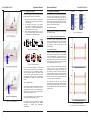
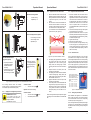
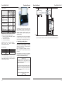
Figure 12: Correct testing of the protective field using
a test rod
5.2.
5.2.1.
Pin 5
= PE
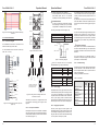
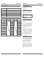
Connection diagram
Time Value in ms
Response time on test signal
t1
≤ tR + 15
Time to test
t2
> t1
Restart time after test
t3
≤ 800
Pin 3
Pin 4
= OSSD 1
Electrical Installation
=0V
Pin 2
= OSSD 2
Pin 1
= + 24 VDC
1
Test input
Transmitter
3
Figure 14: M12/5 Pin connector
Important information:
Safety devices for connection of GuardShield Safe 2
the must be built with PNP logic. The outputs will be
periodically controlled for short-circuit and cross-fault
detection.
open
OSSD 1 / OSSD 2
t1
Receiver
3)
+24 VDC
2
t3
t2
Transmitter
The output voltage at the solid-state outputs is
dependant on the power supply and the output load
(see chapter 11 Technical Data).
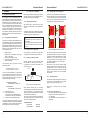
Figure 16: Test timing diagram
0V
2)
1)
tR means the response time of the respective
GuardShield Safe 2 type (see product label).
4
5
Not connected
1) Operation with internal test
2) Test using a relay contact
3) Test using a PNP output
Receiver
0V
1) Operation with internal test
2) Test using a relay contact
3) Test using PNP output
RL
OSSD 1
4
+24 VDC
1)
0V
RL
Test 2
2
Test 1
PE
OSSD 1
PE
+24 VDC
OSSD 2
1
Pin 1 (brown)
Pin 3 (blue)
Pin 4 (black)
0V
+24 VDC
Pin 2 (white)
Pin 1 (brown)
Pin 5 (grey)
Pin 3 (blue)
7
Pin 2 (white)
Not connected
Pin 4 (black)
Pin 5 (grey)
6
3
OSSD 2
2)
Not connected
Not connected
7
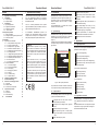
Figure 13: Terminal block connection (see also
Figure 18)
Figure 15: Wiring of the connecting cables of the
M12/5 Pin connector
Transmitter and receiver are supplied with M12/5
pin connectors The wiring is given in Figure 14 and
Figure 15.
5.2.2.
Internal test
Description
Continuous test current
I
Peak test current
IP
Time of peak test current
tP
Internal test
Short circuited (closed)
Open
5.2.3.
3)
5
6
Test input to transmitter
Normally the test input at the transmitter is installed
with a short circuit jumper to activate the transmitter. If
an external test is desired, a contact can be connected
to the test input (Figure 13).
12
The two redundant Output Signal Switching Devices
(OSSD) are fully monitored. Any short circuits are
detected. The maximum load is 0.4 A, higher currents
are limited through short circuit protection. Increased
output loads may be realized using external safety
interfaces.
short circuited
The transmitter and receiver are connected to the
machine control using a 5-wire cable.
For the transmitter and the receiver two M12 (for
cable - Ø 3 ... 6.5 mm)
Outputs
The timing of test input is as follows (Figure 16):
Receiver:
Transmitter
Active
Inactive
Value
10 mA
100 mA
20 µs
Test LED
Transmitter
Green
Red
Power supply
GuardShield Safe 2 safety light curtains are devices
of electrical safety level III (extra low voltage). 24 VDC
± 20 % has to be supplied by a power supply that
complies with IEC / EN 60204 and IEC / EN 60742.
Such a power supply meets the electrical safety
requirements and maintains the minimum power of 18
VDC during 20 ms even in the event of voltage dips.
5.2.4.
5.2.6.
Trouble shooting
Possible errors and operation status are indicated with
the LED indicators on the transmitter and receiver.
Also the Optical Interface has an option that can be
used for the diagnostics
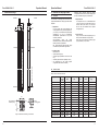
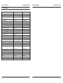
Following combinations are relevant:
Table 1: Transmitter
Status
No power supply
(external)
Test input closed
(external)
Test input open
(external)
Controller error
(internal)
Protective field error
(internal)
Orange
(Power)
off
LED
Green
(ok)
off
Red
(Test)
on
on
on
off
on
off
on
flashing
off
on
flashing
off
flashing
Bringing into operation
After the power supply has been applied to the
GuardShield Safe 2 and the automatic power-up test
is successfully completed (power up test time < 3 s)
the green LED on the receiver and transmitter will light
on. The system is now ready to operate.
13