1
GuardShield Safe 2
Operation Manual
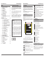
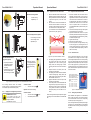
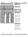
Table 2: Receiver
+24 VDC
Status
LED
Orange Green
(Power)
No power supply
(external)
No sufficient power
(external)
OSSD on (on-load operation,
protective field not interrupted,
normal)
OSSD off (off-load operation,
protective field interrupted or
insufficient alignment of the
system)
OSSD error (external, short
circuit between OSSD 1 and
OSSD 2, towards 0 V and off
24 VDC)
Controller error (internal)
Protective field error (internal)
off
on
off
off
on
off
flashing
off
on
irregular
flashing
flashing
off
flashing
off
on
off
flashing
Normal operation
5.2.7.
2
3
4
5
6
7
2 3
4
5
6
7
1 3 23 24
A1 S33 S34
MSR 4X
all 3s
short time
Internal error (orange LED is irregularly flashing):
Please
contact
the
nearest
ROCKWELL
AUTOMATION representative.
Transmitter
Receiver
Trans mitter
(Protective (Protective
field not
field
interrupted) interrupted)
off
off
on
1
1
Red
External error: An external interface error can be
resolved by correcting the installation, due to
1. Receiver: short circuit of both OSSDs, of OSSD
to Usp, of OSSD to GND
2. Transmitter: Test input open
3. No or too low power supply
Test input closed
Test input closed
Test input open
GuardShield Safe 2
Operation Manual
Receiver
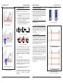
Operation status
OSSD on
OSSD off
OSSD off
Protective field free
Protective field interrupted
Test active
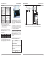
Optical Interface
As an accessory Rockwell Automation offers an
Optical Interface including a software package for
extended diagnostic purposes.
Figure 17: Optical Interface
The adapter may be snapped on the controller during
normal operation and may be connected via the
interface to a MS-Windows personal computer for
diagnoses purposes. A detailed description about
extended diagnostic features is shipped with the
diagnostic package.
The Optical Interface offers apart from the diagnosis
of operating conditions, the possibility to select and
analyse the length of the interrupted protective field.
S21 S22 A2
14 S11 S12
0 VDC
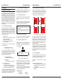
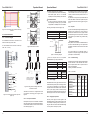
Figure 18: Diagram for automatic reset mode with ROCKWELL AUTOMATION MSR 42
6. Interfacing to safety devices
The interfacing of the light curtain with the machine
control has to be control reliability, i.e. a correct
interface with a safety PLC or safety relays with
positive guided relay contacts.
Figure 18 - Diagram for automatic reset mode shows a diagram of a typical emergency stop relay
component.
Other applications are mentioned in the application
note “Safety Interfaces with GuardShield Safe 2”, on
the ROCKWELL AUTOMATION homepage.
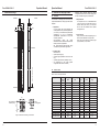
Danger
The safety devices and the interconnection to
the machinery have to comply with the basic
safety requirements as mentioned in the current
regulations and standards.
Direct interfacing of a safety light curtain to machine
control that does not meet the necessary safety
integrity level, i.e. use of general purpose PLCs or
general purpose relays can cause serious injury or
death of persons.
Consult a professional safety engineer!
Danger
14
15