1
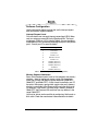
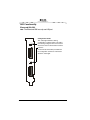
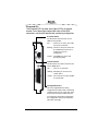
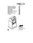
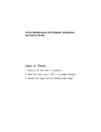
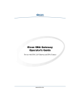
Eiconcard S5x Family
for ISA-Compatible Bus
www.eicon.com
Fourth Edition (July 2001)
203-078-04
Eicon, Eiconcard, and the Eicon logo are either trademarks or registered
trademarks of Eicon Networks Corporation.
Changes are periodically made to the information herein; these changes will be
incorporated into new editions of the publication. Eicon Networks may make
improvements and/or changes in the products and/or programs described in
this publication at any time.
Copyright © 1996-2001 Eicon Networks Corporation. All rights reserved,
including those to reproduce this publication or parts thereof in any form without
permission in writing from Eicon Networks Corporation.
www.eicon.com
Table of Contents
Introduction ................................................................... 5
Installing the Eiconcard S5x.......................................... 6
Making an ISDN Connection......................................... 9
Connecting to an Eicon Networks NT1....................................... 9
Connecting to a Third Party NT1 ................................................ 9
Termination ............................................................................... 11
Making an HSI Connection ......................................... 13
Interface Specifications ............................................... 14
Cable Construction Information ................................................
The V.24 Interface.....................................................................
The V.35 Interface.....................................................................
The X.21 Interface ....................................................................
Null-Modem Cables ..................................................................
15
16
18
20
22
Appendix ..................................................................... 25
Setting the I/O Address ............................................................
Selecting an Interface ...............................................................
Software Configuration .............................................................
LED Functionality .....................................................................
25
27
28
29
Technical Specifications.............................................. 31
International Regulatory Information ........................... 33
www.eicon.com
www.eicon.com
Introduction
The S5x family of Eiconcards are ISA cards that offer X.25
connectivity through one or two (depending on the the Eiconcard
model) high-speed ports (supporting V.24, V.35, or X.21 interfaces)
at speeds of up to 512 Kbps, and/or through an ISDN BRI port
(Eiconcard S51) at speeds of up to 128 kbps (over the “D” channel
or the “B” channels).
Note The Eiconcard S5x also supports protocols such as SDLC,
PPP, and Frame Relay.
All Eiconcards have been tested and found to comply with
the Electromagnetic compatibility, Safety and Network
connection regulations within the European Union, North
America, and other major territories. Read the regulatory
information on page 29 before installing and using your
adapter.
Hardware Features
The Eiconcard S5x features the following:
Eiconcard
CPU/Memory
# of HSI Ports
#of ISDN BRI Ports
Eiconcard S50
20 MHz Motorola 68302 /
2 MB RAM
1
N/A
Eiconcard S51
20 MHz Motorola 68302 /
2 MB RAM
1
1
Eiconcard S52
20 MHz Motorola 68302 /
2 MB RAM
2
N/A
The High-Speed Interface (HSI) ports, support full duplex
communications over a V.24, V.35, or X.21 interface at speeds of up
to 512 Kbps per port (depending on the type of interface selected).
The ISDN BRI port supports transfer rates of up to 128 kbps (over
the “D” channel or the “B” channels).
Power Consumption
Warning: Check that power supply will not be overloaded. Maximum
power consumption of the board is stated above. The user should
check that the total power drawn by the host computer, the
Eiconcard S5x, and any other peripherals, does not exceed the
capability of the host power supply unit.
Introduction
5
Installing the Eiconcard S5x
Follow the steps below to install the Eiconcard S5x. If you want the
Eiconcard S5x to be available to multiple users on a LAN, install it
in the PC that will function as a gateway for the LAN.
1 Prepare the PC
Turn off the PC and disconnect its power cable. Remove the cover
of the PC according to the instructions that came with it.
2 Prepare the Eiconcard
Prepare the Eiconcard S5x by selecting its I/O address and
communications interface.
a) Set the I/O address. The default I/O address is 380h. You only
need to change this setting if another card already installed in
the PC uses an I/O address in the range 380h to 387h. To
change the I/O address, follow the instructions in “Setting the
I/O Address” on page 22, then continue with Step 1(b) below.
b) Select the interface. The default setting enables the V.24 and
V.35 interfaces; to use these interfaces, continue with Step 2
below. To enable the X.21 interface instead, follow the
instructions in “Selecting an Interface” on page 24, then
continue with Step 3.
3 Install the Eiconcard S5x
Drain static electricity from your body by touching the metal
chassis (the unpainted metal at the back of your PC).
b) Locate a slot in your PC that has the same bus type as your
adapter.
If your PC has both ISA and PCI slots, the ISA slots are longer,
as shown.
a)
metal plates
PCI slots
ISA slots
Figure 1. Locating a PCI slot
6
Installing the Eiconcard S5x
If there is a metal plate at the end of the slot, remove it and keep
the screw.
d) Firmly insert the adapter into the selected slot.
To avoid damaging your hardware, insert the adapter
only into a slot with the same bus type as the adapter.
Inserting the adapter into any other type of slot can
damage your adapter, your PC, or both.
c)
screw
ISA
Eiconcard
ISA slot
Figure 2. Inserting the Eiconcard S5x.
Fasten the adapter with the screw (to ensure that the adapter
is properly secured and grounded to the PC’s chassis).
f) Replace the cover of your PC as described in your PC’s
manual.
g) Reconnect the power cable.
Note Although the Eiconcard S5x can be installed in any available
ISA expansion slot (unless the PC’s documentation specifies
otherwise), it is recommended that you install the card in a 16-bit
slot to take advantage of the higher IRQs and memory-address
locations available only through 16-bit slots.
e)
4 Set the interrupt request level and memory segment address
These parameters are set using the Eicon Networks networking
software that you purchased with the Eiconcard S5x. Consult the
documentation included with the networking software for
instructions on how to configure the Eiconcard.
To determine the correct interrupt request level and memory
segment address values to use, follow the instructions in “Software
Configuration” on page 25, then continue with Step 5.
Installing the Eiconcard S5x
7
5 Test the Eiconcard S5x
The application software purchased with the Eiconcard S5x
contains a test program to verify the card’s integrity. Consult the
documentation supplied with this software for details.
6 Connect to the outside world
You are now ready to connect the Eiconcard S5x to the outside
world.
• To set up ISDN connections, consult “Making an ISDN Connection” on page 9.
• To set up an HSI connection, consult “Making an HSI Connection” on page 13.
8
Installing the Eiconcard S5x
Making an ISDN Connection
Note Only the Eiconcard S51 supports ISDN connections.
After you have installed your Eiconcard S51, connect your ISDN
line.
• If you plan to use an Eicon Networks NT1, see “Connecting to
an Eicon Networks NT1,” below.
• If you plan to use a third party NT1 or if you are installing the
Eiconcard S51 outside of North America, see “Making an HSI
Connection” on page 13.
Connecting to an Eicon Networks NT1
To connect to an Eicon Networks NT1, plug one end of the Interface
Cable for ISDN NT1 into the DIN-4 port on the Eiconcard S51; plug
the other end into the DIN-4 port on the NT1. Figure 3 shows how
to make these connections.
Eicon Networks NT1
DIN-4 port
HSI connector
Interface Cable for ISDN NT1
DIN-4 port
Figure 3. Connecting to the Eicon Networks NT1
Making an ISDN Connection
9
Connecting to a Third Party NT1
To connect to a third party NT1, you must use the ISDN S/T Cable.
This cable includes interface circuitry which is not normally provided
by the third party NT1 (but which is provided by Eicon’s NT1).
Plug the ISDN S/T Cable into the DIN-4 port on the card as
illustrated in Figure 4.
• In North America and Australia, you may need to insert the
RJ-45 plug into the terminating resistor, and then insert the
terminating resistor into the S/T connector. The next section,
“Termination,” explains when to use the terminating resistor.
• In the rest of the world, insert the RJ-45 plug directly into the S/T
connector. Do not install the terminating resistor.
Plug the other end of the RJ-45 cable into the S/T port on your NT1.
Figure 4 shows how the ISDN S/T Cable, the terminating resistor
(when required), and the RJ-45 plug connect together.
Terminating resistor
(if required)
ISDN S/T Cable
RJ-45 plug
DIN-4 port
Figure 4. Connecting the ISDN S/T Cable
The interface cable contains fully passive components and does not
affect the energy consumption or other specifications of the
Eiconcard. This passive interface is required to ensure regulatory
compliance and guarantee proper functionality.
10
Connecting to a Third Party NT1
Termination
This section applies to S/T interface users in Australia and North
America, and provides instructions to help set up termination
scenarios. Termination requirements vary according to: the number
of devices connected to the NT1; and the distance between the
devices and the NT1.
For users who require termination, the Eiconcard S51 S/T has been
shipped with a separate terminating resistor. For information on how
to install the terminating resistor, see “Installing a Terminating
Resistor” on page 12.
How do I determine the termination value?
Single ISDN Device
If the NT1 is connected to a single ISDN device (e.g.
Eiconcard S51), follow the instructions below.
75 meters or more
If the connection spans 75 meters (250 feet) or more, connect the
100 ohm terminating resistor included with the ISDN cable. Set the
NT1 to provide 100 ohms of resistance. Consult the manual
provided with the external NT1 for more detailed instructions.
Note Some NT1s do not support connections over 75 meters (250
feet). Check your user documentation to determine the distance
supported.
75 meters or less
If the connection spans less than 75 meters (250 feet), set the NT1
to 50 ohms of resistance, and do not connect the terminating
resistor. Consult the manual provided with the external NT1 for more
detailed instructions.
Termination
11
Multiple ISDN Devices
If the NT1 is connected to more than one ISDN device, follow the
procedures below.
75 meters or more
If the connection spans 75 meters (250 feet) or more, both end
devices on the ISDN bus must be set to 100 ohm termination. If the
Eiconcard is one of the end devices, connect the 100 ohm
terminating resistor included with the ISDN cable. Consult the
manuals provided with the other ISDN devices and NT1 for more
details.
Note Some NT1s do not support connections over 75 meters (250
feet). Check your user documentation to determine the distance
supported
75 meters or less
If the connection spans less than 75 meters (250 feet), set the NT1
to 50 ohms of resistance, and do not connect the terminating
resistor. Set the other ISDN devices to no termination. Consult the
manuals provided with the NT1 and other ISDN devices for more
detailed instructions.
Installing a Terminating Resistor
The terminating resistor is installed by inserting the RJ-45 end of
the ISDN cable into the terminating resistor, and then inserting the
terminating resistor into the ISDN S/T cable (see, “Connecting the
ISDN S/T Cable” on page 10.
12
Termination
Making an HSI Connection
The Eiconcard S5x can connect as a DTE to devices such as Data
Service Units (DSUs) which support one of the following interfaces:
V.24, V.35, or X.21. It can also connect directly to a host computer,
or back-to-back to another Eiconcard. Each HSI port is configured
independently
Table 1 lists the most common connections supported by the HSI
port, and specifies the part number of the required Eicon Networks
cable. For information on making your own cables, see “Interface
Specifications” on page 14.
Interface
Eiconcard S5x
Connection
Cables Required
Part #
V.24
to V.24 DCE (method
1)
HSI V.24 DCE Cable
300-026
to V.24 DCE (method
2)
HSI/V.24 Converter, plus
Standard V.24 cable
300-046*
300-007
to V.24 DTE
or non-HSI Eiconcard
HSI V.24 DCE Cable, plus
HSI Null-Modem Conversion Cable
300-026,
300-033
V.35
X.21
to HSI Eiconcard
HSI V.24/V.35 Null-Modem Cable
300-031
to V.35 DCE
HSI V.35 DCE Cable
HSI V.35 DCE Modem Cable
(France)
300-024
300-086
to V.35 DTE
HSI V.35 DCE Cable, plus
HSI Null-Modem Conversion Cable
300-024,
300-033
to HSI Eiconcard
HSI V.24/V.35 Null-Modem Cable
300-031
to AS/400 port
HSI V.35 Null-Modem Cable for
AS/400
300-047
to X.21 DCE
HSI X.21 DCE Cable
300-025
to X.21 DTE
HSI X.21 DCE Cable, plus
HSI Null-Modem Conversion Cable
300-025,
300-033
to HSI Eiconcard
HSI X.21 Null-Modem Cable
300-032
* Included with the Eiconcard
Table 1. Standard Interface Cables
When you make connections through a null-modem cable—for
example, to a DTE or to the HSI port on another Eiconcard—one
card must be set to internal clocking, and the other to external
clocking.
Consult the documentation which came with your networking
software for more information about port configuration.
Making an HSI Connection
13
Interface Specifications
The standards compliant with the interfaces supported on the HSI
port are listed in Table 2. The rest of this section describes the
allocation of pins used to implement the electrical and signalling
requirements of each interface.
Interface
Standard
Compatibility
V.24
CCITT V.24
Signalling
CCITT V.28
Electrical
V.35
X.21
CCITT X.21bis
Electrical and signalling
RS-232-C
Electrical and signalling
ISO 2110
Connector type for the DCE side of a
V.24 HSI Modem Cable
CCITT V.28
Some signals for electrical
CCITT V.35
Some signals for electrical and signalling
ISO 2593
Connector type for the DCE side of a
V.35 HSI Modem Cable
CCITT X.21
Signalling
CCITT V.11
Electrical
CCITT X.27
Electrical
RS-422-A
Electrical
ISO 4903
Connector type for the DCE side of an
X.21 HSI Modem Cable
Table 2. Interface Compatibility
14
Interface Specifications
Cable Construction Information
If you plan to construct your own HSI cables, be sure to observe the
guidelines given below.
Wire Gauge, Grounding, and Pairing
• Use 26 or 24 AWG wire. Contacts should be 30 microinch gold
flash.
• The cable must be grounded both by a drain wire connected to
pin 1 on both sides (pin A on the type M connector) and by the
braid. Both the drain wire and the braid must be connected to
the connector case and shell at each end of the cable. The braid
must be connected through its full circumference.
• Unused wires must be connected to the cable shield at one end.
• Use an anti-EMI shield.
• Important. Wires identified by a rectangle under the heading
“Twisted pair” must be installed as a twisted pair. If you do not
install twisted pairs correctly, the cable will not work.
Type of Connectors
The HSI port accepts a 26-pin, 3-row male connector. The types of
connectors used on the interface-specific end of the cable are as
follows:
Cable Type
Connectors
V.24 modem
DB25, HSI
V.35 modem
Type M, HSI
X.21 modem
DB15, HSI
V.24/V.35 null-modem
HSI, HSI
X.21 null-modem
HSI, HSI
V.35-AS/400 nullmodem
Type M, HSI
Null-modem conversion HSI, HSI
Table 3. Connector Types
Cable Construction Information
15
The V.24 Interface
1 10
19
A pin-out diagram for the V.24
DCE interface is shown in
Figure 5. The signal definitions
and names are listed in Table 4.
PGND
TXD
RXD
RTS
CTS
DSR
SGND
DCD
TEST
DTR
RLB
RI
TCLK
DTECLK
TI
RCLK
Figure 5. V.24 Interface
Pin #
1
2
3
4
5
6
7
8
15
17
18
20
21
22
24
25
Signal
PGND
TXD
RXD
RTS
CTS
DSR
SGND
DCD
TCLK
RCLK
TEST
DTR
RLB
RI
DTECLK
TI
Name
Protective Ground
Transmit Data
Receive Data
Request to Send
Clear to Send
Data Set Ready
Signal Ground
Data Carrier Detect
Transmit Clock (DCE)
Receive Clock
Local Loopback Activation
Data Terminal Ready
Remote Loopback
Ring Indicator
Transmit Clock (DTE)
Test Indicator
Direction
Common
Output
Input
Output
Input
Input
Common
Input
Input
Input
Output
Output
Output
Input
Output
Input
Table 4. V.24 DCE Interface Signals
16
The V.24 Interface
CCITT #
101
103
104
105
106
107
102
109
114
115
141
108
140
125
113
142
The V.35 Interface
A pin-out diagram for the V.35
interface is shown in Figure 6.
The signal definitions and names
are listed in Table 5.
1 10
19
RCLKPGND
RXD+
RTS
CTS
DSR
CLK+
SGND
DCD
RCLK+
TXD+
DTR
RXDRLB
CLKRI
TCLK+
TCLKTI
TXDTEST
Figure 6. V.35 Interface
Pin #
Signal
Name
Direction
CCITT #
1
PGND
Protective Ground
Common
101
4
RTS
Request to Send
Output
105
5
CTS
Clear to Send
Input
106
6
DSR
Data Set Ready
Input
107
7
SGND
Signal Ground
Common
102
8
DCD
Data Carrier Detect
Input
109
9
RCLK+
Receive Clock from Modem
Input
115A
10
RCLK-
Receive Clock from Modem
Input
115B
11
RXD+
Receive Data
Input
104A
12
RXD-
Receive Data
Input
104B
13
CLK-
Transmit Clock to Modem
Output
113B
14
TCLK+
Transmit Clock from Modem
Input
114A
16
CLK+
Transmit Clock to Modem
Output
113A
18
TEST
Local Loopback Activation
Output
141
19
TXD+
Transmit Data
Output
103A
20
DTR
Data Terminal Ready
Output
108
21
RLB
Remote Loopback
Output
140
22
RI
Ring Indicator
Input
23
TCLK-
Transmit Clock from Modem
Output
25
TI
Test Indicator
Input
26
TXD-
Transmit Data
Output
125
114B
142
103B
Table 5. V.35 Interface Signals
The V.35 Interface
17
The X.21 Interface
1 10
19
A pin-out diagram for the X.21
interface is shown in Figure 7.
The signal definitions and names
are listed in Table 6.
S(B)
PGND
R(A)
R(B)
I(B)
B(A)
I(A)
SGND
T(A)
C(B)
B(B)
C(A)
T(B)
S(A)
Figure 7. X.21 Interface
Pin #
Signal
Name
Direction
CCITT #
1
7
9
10
11
12
13
14
16
19
20
23
24
26
PGND
SGND
S(A)
S(B)
R(A)
R(B)
I(B)
B(A)
I(A)
T(A)
C(B)
B(B)
C(A)
T(B)
Protective Ground
Signal Ground
Signal Element Timing (+)
Signal Element Timing (-)
Receive Data (+)
Receive Data (-)
Indication (-)
Byte Timing (+)
Indication (+)
Transmit Data (+)
Control Signal (-)
Byte Timing (-)
Control Signal (+)
Transmit Data (-)
Common
Common
Input
Input
Input
Input
Input
Input
Input
Output
Output
Input
Output
Output
101
102
115A
115B
104A
104B
109B
114A
109A
103A
105B
114B
105A
103B
Table 6. X.21 Interface Signals
18
The X.21 Interface
Null-Modem Cables
The wiring diagrams below shows the connections required to
construct a back-to-back HSI—HSI cable, and V.35 - AS/400 cable.
For additional information required to construct your own cables,
see “Cable Construction Information” on page 15.
TWISTED PAIRS
(MANDATORY)
HSI
1
2
3
4
5
6
7
8
DRAIN WIRE
HSI
1
3
2
8
20
7
4
5
9
14
10
16
13
23
11
12
19
26
10
23
9
14
24
13
16
15
17
19
26
20
24
11
12
6
15
17
BRAID
Figure 8. HSI V.24/V.35 Null-Modem Cable (300-031)
Null-Modem Cables
19
TWISTED PAIRS
(MANDATORY)
HSI
HSI
DRAIN WIRE
1
7
11
12
13
16
19
26
20
24
1
7
19
26
20
24
11
12
13
16
BRAID
Figure 9. HSI X.21 Null-Modem Cable (300-032)
TWISTED PAIRS
(MANDATORY)
HSI
1
4
5
6
7
8
14
9
10
23
11
12
Type M
DRAIN WIRE
A
F
H
B
C
D
U
W
P
S
X
AA
V
Y
R
T
E
13
16
19
26
20
BRAID
Figure 10. HSI V.35 Null-Modem Cable for AS/400 (300-047)
20
Null-Modem Cables
TWISTED PAIRS
(MANDATORY)
HSI
1
2
3
4
5
6
7
8
DRAIN WIRE
HSI
1
3
2
8
20
7
4
5
9
14
10
16
13
23
11
12
19
26
10
23
9
14
24
13
16
15
17
19
26
20
24
11
12
6
15
17
BRAID
Figure 11. HSI Null-Modem Conversion Cable (300-033)
Null-Modem Cables
21
Appendix
Setting the I/O Address
The Eiconcard S5x is shipped with the I/O address set to 380h. This
setting only needs to be changed if another card in your PC uses an
I/O address in the range 380h to 387h.
You can set the Eiconcard to use any of the standard I/O addresses
listed in Table 7. Remember that no other card can use the same
address, or the next seven higher values (for example, if you choose
378, no other card can use any value from 378 to 385).
Address
1
2
3
4
Address
1
2
3
4
278h
off
off
off
off
380h
off
on
off
off
280h
off
off
off
on
388h
off
on
off
on
378h
off
off
on
off
390h
off
on
on
off
380h
off
off
on
on
398h
off
on
on
on
Table 7. I/O Address Switch Positions
If you are installing more than one Eiconcard in the PC, be sure to
read about the additional address options described on the next
page.
To change the preset I/O address value, adjust the switches shown
in Figure 12 to match the values given in Table 7.
Hold the card as shown when
setting the I/O address, to
ensure the switches are oriented
correctly.
OFF (open)
ON (closed)
Figure 12. I/O Address Switch
22
Appendix
Setting I/O Addresses when Installing Multiple Eiconcards
If you are installing two or more Eiconcards in the PC, for every
Eiconcard installed at a primary I/O address, you can install one at
a secondary I/O address. This reduces the number of I/O addresses
consumed since primary and secondary I/O addresses occupy the
same position in the PC I/O address space.
Primary and secondary I/O addresses differ in the setting of
switch 1, as described in Table 8. To select a secondary I/O
address, set switch 1 to the ON position.
Primary
Secondary
1 Off
1 On
2
3
4
278h
678h
off
off
off
280h
680h
off
off
on
378h
778h
off
on
off
380h
780h
off
on
on
380h
780h
on
off
off
388h
788h
on
off
on
390h
790h
on
on
off
398h
798h
on
on
on
Table 8. I/O Address Selection
Note A secondary I/O address cannot be used if its associated
primary address conflicts with another card. Always verify that each
card installed in your PC has a unique I/O address.
Setting the I/O Address
23
Selecting an Interface
The Eiconcard S5x is capable of connecting as a DTE to devices
which support the V.24, V.35, or X.21 interface. It can also connect
directly to a host computer or back-to-back to another Eiconcard.
The Eiconcard S5x is shipped with the HSI port set to the V.24 and
V.35 interfaces. If you wish to use the X.21 interface, you must
reposition the jumper located next to the HSI connector.
To change the jumper from position A (V.24/V.35) to position B
(X.21), lift it straight up off the board, then position it above the
center and rightmost rows of pins. Carefully press it down onto the
pins. Figure 13 shows the jumper in position B.
If you find the jumper hard to move, use a small slotted screwdriver
to edge it up gradually from each side until you can lift it off.
A
B
To select the X.21 interface,
position the jumper on the two
rows of pins to the right of the “A”
printed on the Eiconcard.
Figure 13. Selecting an Interface
24
Selecting an Interface
Software Configuration
Use the information below to assign the card’s interrupt request
level and memory segment address.
Interrupt Request Level
Only one device can use each interrupt request level (IRQ). Make
sure you assign an unused IRQ to the Eiconcard S5x. The usual
assignment of IRQs in a PC is listed in Table 9. You may be able to
make additional IRQs available by disabling serial port 2 and parallel
port 2. Consult your PC manual for details.
IRQ
Usual Assignment
2
3
4
5
6
7
10
11
12
14
15
Available
Serial Port 2
Serial Port 1
Parallel Port 2
Diskette Controller
Parallel Port 1
Available (16-bit slot)
Available (16-bit slot)
Available (16-bit slot)
Fixed Disk
Available (16-bit slot)
Table 9. Usual Interrupt Request Level Assignments
Memory Segment Addresses
Some 16-bit peripheral cards (such as LAN adapters) use memory
windows—areas of contiguous memory which fall somewhere
within one of three 128k memory group addresses (A000-BFFF,
C000-DFFF, and E000-FFFF). If such a card is installed in your PC,
the entire 128k memory group which contains the card’s memory
window is unavailable to the Eiconcard S5x and other 8-bit cards.
For example, if you have a LAN card using a memory window at
C800-CFFF, the Eiconcard S5x could not use any address in the
range C000-DFFF.
You may be able to resolve conflicts by configuring 16-bit cards as
8-bit cards. Check the manufacturer’s documentation for details.
Software Configuration
25
LED Functionality
Eiconcard S50, S52
Note The Eiconcard S50 has only one HSI port.
Configuration Status
This status light illuminates during
configuration to indicate which card and/or
port is being configured. This is most useful
when more than one Eiconcard is installed
in the PC.
Consult the documentation provided with
the configuration software for information
about this status light.
26
LED Functionality
Eiconcard S51
The Eiconcard S51 has three status lights (LEDs) on the end
bracket. Two of these lights indicate the status of the ISDN
connection, and the third identifies the card during configuration.
D-channel Status
The D-channel controls the link to your
ISDN service provider.
Off ..........The line is not active. The cable
may not be connected.
Blinking .. The line is active, but a link can’t
be established. This may be a
symptom of incorrect
configuration.
Steady.... The ISDN line is active and
operating normally.
B-channel Status
The B-channels are used for the link to the
remote ISDN device.
Off .......... There is no connection.
Blinking .. Attempting to connect to the
remote device.
Steady ... The connection is active and able
to transmit data.
Configuration Status
This status light illuminates during
configuration to indicate which card is being
configured. This is most useful when more
than one Eiconcard is installed in the PC.
Consult the documentation provided with
the configuration software for information
about this status light.
LED Functionality
27
Technical Specifications
Technical Data
• IBM PC, PC AT, and PS/2 Model 30 bus compatible
Eiconcard
CPU/Memory
# of HSI Ports
#of ISDN BRI Ports
Eiconcard S50
20 MHz Motorola 68302 /
2 MB RAM
1
N/A
Eiconcard S51
20 MHz Motorola 68302 /
2 MB RAM
1
1
Eiconcard S52
20 MHz Motorola 68302 /
2 MB RAM
2
N/A
Hardware Installation
• Interrupt levels selectable via software (2, 3, 4, 5, 6, 7, 10, 11, 12, 14, 15)
• I/O address selectable via on-board switch (14 options)
• 4Kb shared memory access with a software selectable starting address
(48 options in the ranges of C000 to EF00 and FC000 to FEF00)
External Interface
Eiconcard
External Interface
Eiconcard S50
One 26-pin “D Type” female ports.
Eiconcard S51
One 26-pin “D Type” female port and one DIN-4 female connector.
Eiconcard S52
Two 26-pin “D Type” female port.
Performance
• 2 Mbps full duplex per physical HSI port (V.35, X.21, NRZ, NRZI)
• 128 kbps per ISDN BRI port (over the “D” channel or the “B” channels)
Power Requirements
• 3 A at +5 Volts
• 80 mA at +12 Volts
• 50 mA at -12 Volts
Environmental Requirements
•
•
•
•
Operating temperature: 0°C to 50°C
Operating humidity: 0 to 90% (non-condensing)
Barometric operating pressure: 86 to 106 kPascals
Maximum tolerance in power supply variation: +5% to -5%
HSI Ports
•
•
•
•
•
28
HSI ports connect to 26-pin high-density male connectors
Support for V.24,X.21bis, and V.35
X.21 with V.11 (X.27) signaling
NRZ, NRZI, and FM data encoding
Internal or external clocking (DTE or DCE) or split (transmit internal,
receive external)
Technical Specifications
International Regulatory Information
Regulatory Information for the USA:
WARNING. Changes or modifications to this unit not expressly approved by
Eicon Networks Corporation could void the user's authority to operate the
equipment.
Declaration of Conformity
We:
Eicon Networks Corporation
2155 Chenault Drive, Suite 503
Carrollton, Texas USA 75006
1-800-80-EICON
(972) 417-5500
Fax: (972) 417-5610
Declare under our sole legal responsibility that the products listed below to
which this declaration relates, are in conformity with Part 15 of the FCC Rules.
Operation is subject to the following two conditions:
(1) This device may not cause harmful interference, and
(2) This device must accept any interference received, including interference
that may cause undesired operation.
Note: This equipment has been tested and found to comply with the limits for
a Class B digital device, pursuant to Part 15 of the FCC Rules. These limits are
designed to provide reasonable protection against harmful interference in a
residential installation. This equipment generates, uses and can radiate radio
frequency energy and, if not installed and used in accordance with the
instructions, may cause harmful interference to radio communications.
However, there is no guarantee that interference will not occur in a particular
installation. If this equipment does cause harmful interference to radio or
television reception, which can be determined by turning the equipment off and
on, the user is encouraged to try to correct the interference by one or more of
the following measures:
• Reorient or relocate the receiving antenna.
• Increase the separation between the equipment and receiver.
• Connect the equipment into an outlet on a circuit different from that to
which the receiver is connected.
Consult the dealer or an experienced radio/TV technician for help.
International Regulatory Information
29
FCC Part 68 Notice
This unit complies with Part 68 of the FCC rules. On the bottom of this
equipment is a label that contains, among other information, the FCC
registration number. If requested, this information must be provided to the
telephone company.
An FCC compliant telephone cord and modular plug is provided with this
equipment, designed to be connected to the telephone network or premises
wiring using a compatible modular jack which is Part 68 compliant.
This equipment cannot be used on telephone company-provided coin
service. Connection to party line service is subject to state tariffs.
If this equipment causes harm to the telephone network, the telephone
company will notify you in advance that temporary discontinuance of service
may be required. If advance notice isn't practical, the telephone company will
notify the customer as soon as possible. Also, you will be advised of your right
to file a complaint with the FCC if you believe it is necessary.
The telephone company may make changes in its facilities, equipment,
operations, or procedures that could affect the operation of the equipment. If
this happens, the telephone company will provide advance notice in order for
you to make the necessary modifications in order to maintain uninterrupted
service.
If trouble is experienced with this equipment, please contact us for repair and
warranty information. If the trouble is causing harm to the telephone network,
the telephone company may request you remove the equipment from the
network until the problem is resolved.
Facility Interface
code
Digital Reg.
code
Service Order
code
USOC Jack
Type
S/T
021S5
XD
6.0N
N/A
U
021S5
DE
6.0N
RJ-49 C
Should you experience trouble with this equipment, please contact the address
on the previous page.
30
Regulatory Information for the USA:
Regulatory Information for Canada
NOTICE: The Industry Canada label identifies certified equipment. This
certification means that the equipment meets certain telecommunications
network protective, operational and safety requirements. Industry Canada does
not guarantee the equipment will operate to the user’s satisfaction.
Before installing this equipment, users should ensure that it is permissible to be
connected to the facilities of the local telecommunications company. The
equipment must also be installed using an acceptable method of connection.
In some cases, the company’s inside wiring associated with a single line
individual service may be extended by means of certified connector assembly
(telephone extension cord). The customer should be aware that compliance
with the above conditions may not prevent degradation of service in some
situations.
Warning: For your safety, follow these steps before you remove the
cover from your PC:
1. Turn off the power to your PC and all peripheral devices.
2. Disconnect the power cable.
Repairs to certified equipment should be made by an authorized Canadian
maintenance facility designated by the supplier. Any repairs or alterations made
by the user to this equipment, or equipment malfunctions, may give the
telecommunications company cause to request the user to disconnect the
equipment.
For their own protection, users should ensure that any electrical ground
connections of the power utility, telephone lines and internal metallic water pipe
system are connected together. This precaution is particularly important in rural
areas.
Warning: Users should not attempt to make such connections
themselves, but should contact the appropriate electric inspection
authority, or electrician, as appropriate.
This Class B digital apparatus complies with Canadian ICES-003.
Cet appareil numérique de la classe B est conforme à la norme NMB-003 du
Canada.
Regulatory Information for Canada
31
Regulatory Information for Europe
EU Declaration of Conformity
EN: Eicon Networks Corporation declares that this equipment is in compliance
with the essential requirements and other relevant provisions of
Directive1999/5/EC.
DE: Eicon Networks Corporation erklärt, daß diese
Telekommunikations-endeinrichtung den grundlegenden Anforderungen und
anderen relevanten Bestimmungen der Richtlinie 1999/5/EG entspricht.
DK: Eicon Networks Corporation erklærer, at dette udstyr er i
overensstemmelse med vigtige krav og andre relevante provisioner i Direktiv
1999/5/EC.
ES: Eicon Networks Corporation declara que este equipo cumple con los
requisitos esenciales y otras disposiciones pertinentes de la Directiva
1999/5/EC.
FI: Eicon Networks Corporation takaa, että tämä laite on 1999/5/EC-direktiivin
olennaisten vaatimusten ja muiden lausekkeiden mukainen.
FR: Eicon Networks Corporation déclare que cet équipement répond aux
exigences essentielles et autres dispositions pertinentes de la directive
1999/5/EC.
GR: Eicon Networks Corporation ðÒÔ‚·flÌÂÈ ÛÙÁÌ ·Ì·ÍÔflÌ˘ÛÁ ¸ÙÈ ·ıÙ‹ Ù·
ÏÁ˜·ÌfiÏ·Ù· ›˜ÔıÌ ÙÈÚ ‚·ÛÈÍ›Ú ·ð·ÈÙÔ˝ÏÂÌÂÚ ðÒԉȷ„Ò·ˆ›Ú Í·È ıð¸ÍÂÈÌÙ·È
ÛÙÈÚ ıð¸ÎÔÈðÂÚ Û˜ÂÙÈÍ›Ú ‰È·Ù‹ÓÂÈÚ ÙÁÚ œ‰Á„ÁÙÈÍfiÚ 1999/5/EC.
IC: Eicon Networks Corporation lýsir hér með yfir að þetta tæki uppfyllir
grunnkröfur og tengd ákvæði ESB tilskipunar nr. 1999/5/EC.
IT: La Eicon Networks Corporation certifica che la presente apparecchiatura
è conforme ai requisiti di legge stabiliti nella direttiva 1999/5/EC.
NL: Eicon Networks Corporation verklaart, dat deze uitrusting in
overeenstemming is met de essentiële vereisten en andere relevante
bepalingen van Richtlijn 1999/5/EC.
NO: Eicon Networks Corporation erklærer herved at dette utstyret oppfyller de
vesentligste krav og relevante bestemmelser i direktiv 1999/5/EF om radio- og
teleterminalutstyr.
PT: A Eicon Networks Corporation declara que este equipamento está de
acordo com os requisitos básicos e outras provisões relevantes da Directiva
1999/5/EC.
SE: Eicon Networks Corporation förklarar att denna utrustning
överensstämmer med de väsentliga krav och regler som finns i direktivet
1999/5/EG.
To receive a detailed R&TTE Declaration for this product please send a request
specifying the product name to the following e-mail address:
[email protected].
32
Regulatory Information for Europe
Safety Status: SELV
No voltages within this equipment exceed SELV voltages. All interconnection
points and ports are SELV.
User/Installer Instructions for the United Kingdom
Important Safety Considerations When Installing Into A Host
Computer System
The Eiconcard S5x is a single PCI card.
Installation Within A Spare Slot Position
Warning: It is essential that, when other option cards are introduced
which use or generate a hazardous voltage, the minimum creepages
and clearances specified in the table below are maintained. Suitable
user protection to ensure compliance with EN60950/A4 should be
present on the card. A hazardous voltage is one which exceeds 42.4V
peak a.c or 60V d.c. If you have any doubt, seek advice from a
competent engineer before installing other adapters into the host
equipment.
The equipment must be installed such that with the exception of the
connections to the host, clearance and creepage distances shown in the table
below are maintained between the card and any other assemblies which use
or generate a voltage shown in the table below.
Clearance
X mm
Creepage
Y mm
Voltage used or generated by other
parts of the host or expansion card
Vrms or Vdc
2.0
2.4 (3.8)
up to 50
2.6
3.0 (4.8)
up to 125
4.0
5.0 (8.0)
up to 250
4.0
6.4 (10.0)
up to 300
Table 10. Creepage Distances
The larger distance shown in brackets applies where the local environment
within the host is subject to conductive pollution or dry non-conductive pollution
which could become conductive due to condensation. Failure to maintain these
minimum distances would invalidate the approval.
The clearance distance X is the shortest distance in air between two points.
The creepage path Y (along surfaces) is the shortest distance between the
same two points.
Regulatory Information for Europe
33
Regulatory information for Australia
• This customer equipment shall only be installed in a PC that requires the
use of a tool to gain access to internal parts (e.g. this customer equipment
must not be installed in a PC with a ‘flip lid’).
• Proper installation of the Eiconcard S5x card requires that it is screwed to
the metal backplate of the computer. This ensures proper grounding, which
is necessary for safety purposes.
• This customer equipment may only be installed in host equipment where
there is at least 2 mm of air gap between the customer equipment and
adjacent boards (PCBs).
• Only ACA permitted line cord set(s) or made from ACA certified components shall be used as replacements with this customer equipment.
Eiconcard S5x
Warning: This customer equipment is to be installed and maintained
by service personnel as defined by AS/NZS 3260 Clause 1.2.14.3
Service Personnel. It may be hazardous if your computer is not
properly plugged in and grounded.
34
Regulatory information for Australia
203-078-04