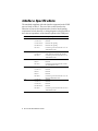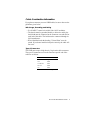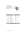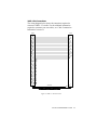
1
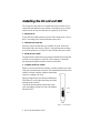
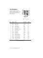
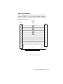
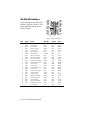
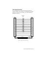
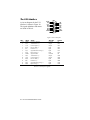
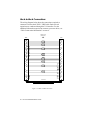
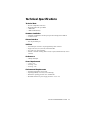
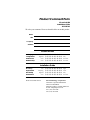
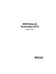
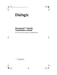
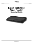
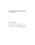
EiconCard S90
for PCI-Compatible Bus
Installation Guide
203-187-01
First Edition (March 1998)
Eicon, EiconCard, and EiconCard S90 are trademarks of Eicon Technology
Corporation.
Changes are periodically made to the information herein; these changes will be
incorporated into new editions of the publication. Eicon Technology may make
improvements and/or changes in the products and/or programs described in this
publication at any time.
A product comment form is provided at the back of this publication. If the form has
been removed, address your comments to the attention of Corporate Publications at
the address shown below, or by electronic mail to [email protected].
Eicon Technology may use or distribute whatever information you supply in any way
it believes appropriate without incurring any obligations to you.
Copyright © 1998 Eicon Technology Corporation. All rights reserved, including
those to reproduce this publication or parts thereof in any form without permission
in writing from Eicon Technology Corporation.
Eicon Technology Corporation
9800 Cavendish Blvd.
Montreal, Quebec
Canada, H4M 2V9
Table of Contents
Introduction............................................................................ 5
Installing the EiconCard S90 ................................................. 6
Selecting an Interface............................................................. 7
Interface Specifications.......................................................... 8
Cable Construction Information ............................................................ 9
The V.24 Interface ................................................................................ 10
The V.35 Interface ................................................................................ 12
The EIA-530 Interface ......................................................................... 14
The V.36/RS-449 Interface................................................................... 16
The X.21 Interface ............................................................................... 18
Back-to-Back Connections .................................................................. 20
Technical Specifications ...................................................... 21
International Regulatory Information .................................. 22
Limited Warranty................................................................. 25
Introduction
The EiconCard S90 is a PCI Plug-and-Play (PnP) card that offers
X.25 connectivity through a high-speed port (supporting V.24, V.35,
EIA-530, V.36/RS-449, or X.21 interfaces) at speeds of up to 2 Mbps.
Note The EiconCard S90 also supports protocols such as SDLC,
PPP, and Frame Relay.
Hardware Features
The EiconCard S90 features a 25 MHz Motorola 68302
microprocessor with 1 MB of RAM and 1 MB of FLASH memory. It
has one independent Very High-Speed Interface (VHSI) port,
supporting full duplex communications over a V.24, V.35, EIA-530,
V.36/RS-449, or X.21 interface at speeds of up to 2 Mbps (depending
on the type of interface selected).
Ease of Use
The EiconCard S90 features automatic interface selection. The
intelligent controller on the card detects the type of cable connected
to the VHSI port and automatically selects the matching interface.
About this Manual
This guide describes how to install the EiconCard S90 in any
computer with an IBM PC-compatible PCI bus. It covers the
following topics:
• Installing the card and connecting cables.
• Interpreting the status light on the card.
For instructions on setting up communications protocols and using
applications, consult the documentation provided with your
networking software.
EiconCard S90 Installation Guide
5
Installing the EiconCard S90
The steps below describe how to install the EiconCard S90. If you
want the EiconCard S90 to be available to multiple users on a LAN,
install it in the PC that will function as a gateway for the LAN.
1 Prepare the PC
Turn off the PC and disconnect its power cable. Remove the cover of
the PC according to the instructions that came with it.
2 Install the EiconCard S90
Insert the EiconCard S90 into any available PCI port. Secure the
EiconCard S90 to the chassis of the PC using the bracket-retaining
screw. Reinstall the cover of the PC and reconnect the power cable.
3 Test the EiconCard S90
The application software that you purchased with the EiconCard S90
includes a test program to verify the card’s integrity. Consult the
documentation supplied with this software for details.
4 Configure the EiconCard S90
Before you can use the EiconCard S90, you must configure it to work
with your communications software. The documentation which came
with this software contains complete instructions
on how to configure the card.
During configuration, note that the LED flashes.
This feature is useful when more than one card is
installed in the same PC.
Consult the documentation which came with
your networking software for more information
about the LED.
LED
Port
Figure 1. End Bracket
6
EiconCard S90 Installation Guide
Selecting an Interface
The EiconCard S90 can connect as a DTE to devices such as Data
Service Units (DSUs) which support one of the following interfaces:
V.24, V.35, EIA-530, V.36/RS-449, or X.21. It can also connect
directly to a host computer, or back-to-back to another EiconCard.
Table 1 lists the most common connections supported by the VHSI
port, and specifies the part number of the required Eicon Technology
cable. For information on making your own cables, see “Interface
Specifications” on page 8.
Interface
Connection
Part #
V.24
to V.24 DCE
300-077
to V.24 DTE
300-078
V.35
to V.35 DCE
300-076
to V.35 DCE (France)
300-083
EIA-530
to EIA-530 DCE
300-080
V.36/RS-449
to V.36/RS-449 DCE
300-079
X.21
to X.21 DCE
300-081
Direct
to VHSI port on another EiconCard S90 or
compatible Eicon Technology EiconCard
300-075
Table 1. Standard Interface Cables
To use an interface, simply install the appropriate cable. The
EiconCard S90 recognizes the cable and automatically prepares the
port for that interface.
Consult the documentation which came with your networking
software for more information about port configuration.
EiconCard S90 Installation Guide
7
Interface Specifications
The standards compliant with each interface supported on the VHSI
port are listed in Table 2. The rest of this section describes the
allocation of pins used to implement the electrical and signaling
requirements of each interface. A wiring diagram is also provided, to
show the correspondence of the interface pinout to the VHSI port.
Interface
Standard
Compatibility
V.24
CCITT V.24
Signaling
CCITT V.28
Electrical
CCITT X.21bis
Electrical and signaling
EIA RS-232-C
Electrical and signaling
ISO 2110
Connector type for the DCE side of a V.24
VHSI Modem Cable
CCITT V.28
Some signals for electrical
CCITT V.35
Some signals for electrical and signaling
ISO 2593
Connector type for the DCE side of a V.35
VHSI Modem Cable
RS-422
Electrical
V.35
EIA-530
V.36/RS-449
X.21
RS-423
Electrical
ISO 2110
Connector type for the DCE side of a EIA530 VHSI Modem Cable
CCITT V.10
Electrical
CCITT V.11
Electrical
RS-422
Electrical
RS-423
Electrical
ISO 4902
Connector type for the DCE side of a V.36/
RS-449 VHSI Modem Cable
CCITT X.21
Signaling
CCITT V.11
Electrical
CCITT X.27
Electrical
EIA RS-422-A
Electrical
ISO 4903
Connector type for the DCE side of an X.21
VHSI Modem Cable
Table 2. Interface Compatibility
8
EiconCard S90 Installation Guide
Cable Construction Information
If you plan to construct your own VHSI cables, be sure to observe the
guidelines given below.
Wire Gauge, Grounding, and Pairing
• Use 28 AWG 7-strand wire with 0.020–0.028" insulation.
• The chassis must be grounded both by a drain wire and by the
braid; both must be connected to the connector case and shell at
each end of the cable. The braid must be connected through its
full circumference.
• Wires identified under the heading “Twisted Pairs” must be
paired. If you do not install twisted pairs correctly, the cable will
not work.
Type of Connectors
The VHSI port accepts a high density 36-pin male cable connector.
The types of connectors used on the interface-specific end of the
cable are as follows:
Interface
Connector
V.35
Type M
V.24
DB25
V.36/RS-449
DB37
EIA-530
DB25
X.21
DB15
Table 3. Connector Types
EiconCard S90 Installation Guide
9
The V.24 Interface
A pin-out diagram for the V.24
interface is shown in Figure 2. The
signal definitions and names are
listed in Table 4.
PG N D
TXD
RXD
RTS
CTS
DSR
SG N D
DCD
1
14
TCLK
RCLK
TEST
DTR
RLB
RI
DTECLK
TI
25
13
Figure 2. V.24 Interface
Pin #
1
2
3
4
5
6
7
8
15
17
18
20
21
22
24
25
Signal
PGND
TXD
RXD
RTS
CTS
DSR
SGND
DCD
TCLK
RCLK
TEST
DTR
RLB
RI
DTECLK
TI
Name
Protective Ground
Transmit Data
Receive Data
Request to Send
Clear to Send
Data Set Ready
Signal Ground
Data Carrier Detect
Transmit Clock (DCE)
Receive Clock
Local Loopback Activation
Data Terminal Ready
Remote Loopback
Ring Indicator
Transmit Clock (DTE)
Test Indicator
Direction
Common
Output
Input
Output
Input
Input
Common
Input
Input
Input
Output
Output
Output
Input
Output
Input
Table 4. V.24 Interface Signals
10
EiconCard S90 Installation Guide
CCITT #
101
103
104
105
106
107
102
109
114
115
141
108
140
125
113
142
VHSI—V.24 Connections
The wiring diagram below shows the connections required to
construct a VHSI—V.24 cable. For the additional information
required to construct your own cables, see “Cable Construction
Information” on page 9.
VHSI
V.24
7
9
11
12
13
15
16
18
20
21
25
30
33
34
1
2
3
19
5
17
6
10
8
14
23
35
24
28
26
32
23
35
24
5
6
2
8
15
17
22
3
18
4
20
21
25
7
1
DRAIN WIRE
BRAID
Figure 3. VHSI—V.24 Connections
EiconCard S90 Installation Guide
11
The V.35 Interface
A pin-out diagram for the V.35
interface is shown in Figure 4. The
signal definitions and names are
listed in Table 5.
SGND
CTS
DCD
RI
TEST
RLB
R XD +
R XD R C LK +
R C LK -
B
TI
NN
A
P G ND
RTS
DSR
DTR
T X D+
TX DCLK+
CLKT CLK+
TCLK-
MM
Figure 4. V.35 Interface
Pin #
A
B
C
D
E
F
H
J
L
N
P
R
S
T
U
V
W
X
Y
AA
NN
Signal
Name
Direction
CCITT #
PGND
SGND
RTS
CTS
DSR
DCD
DTR
RI
TEST
RLB
TXD+
RXD+
TXDRXDCLK+
RCLK+
CLKRCLKTCLK+
TCLKTI
Protective Ground
Signal Ground
Request to Send
Clear to Send
Data Set Ready
Data Carrier Detect
Data Terminal Ready
Ring Indicator
Local Loopback Activation
Remote Loopback
Transmit Data
Receive Data
Transmit Data
Receive Data
Transmit Clock (DTE)
Receive Clock (DCE)
Transmit Clock (DTE)
Receive Clock (DCE)
Transmit Clock (DCE)
Transmit Clock (DCE)
Test Indicator
Common
Common
Output
Input
Input
Input
Output
Input
Output
Output
Output
Input
Output
Input
Output
Input
Output
Input
Input
Input
Input
101
102
105
106
107
109
108
125
141
140
103A
104A
103B
104B
113A
115A
113B
115B
114A
114B
142
Table 5. V.35 Interface Signals
12
EiconCard S90 Installation Guide
VHSI—V.35 Connections
The wiring diagram below shows the connections required to
construct a VHSI—V.35 cable. For the additional information
required to construct your own cables, see “Cable Construction
Information” on page 9.
TWISTED PAIRS
(MANDATORY)
VHSI
V.35
Y
AA
R
T
V
X
P
S
U
W
D
E
F
J
L
C
H
N
NN
B
A
5
23
6
24
8
26
10
28
14
32
9
11
13
18
21
25
30
33
34
36
1
3
19
DRAIN WIRE
BRAID
Figure 5. VHSI—V.35 DCEConnections
EiconCard S90 Installation Guide
13
The EIA-530 Interface
A pin-out diagram for the EIA-530
interface is shown in Figure 6. The
signal definitions and names are
listed in Table 6.
PG ND
TXD+
RXD+
RTS+
CTS+
DSR+
SG N D
DCD+
RTXCDCDCL KTRXCCTS-
1
13
14
25
TXDTRXC+
RXDRTXC+
TEST
RTSDTR+
RLB
DSRDTRCLK+
TI
Figure 6. EIA-530 Interface
Pin #
1
2
3
4
5
6
7
8
9
10
11
12
13
14
15
16
17
18
19
20
21
22
23
24
25
Signal
Name
Direction
CCITT #
EIA #
PGND
TXD+
RXD+
RTS+
CTS+
DSR+
SGND
DCD+
RTXCDCDCLKTRXCCTSTXDTRXC+
RXDRTXC+
TEST
RTSDTR+
RLB
DSRDTRCLK+
TI
Protective Ground
Transmit Data
Receive Data
Request to Send
Clear to Send
Data Set Ready
Signal Ground
Data Carrier Detect
Receive Clock (DCE)
Data Carrier Detect
Transmit Clock (DTE)
Transmit Clock (DCE)
Clear to Send
Transmit Data
Transmit Clock (DCE)
Receive Data
Receive Clock (DCE)
Local Loopback
Request to Send
Data Terminal Ready
Remote Loopback
Data Set Ready
Data Terminal Ready
Transmit Clock (DTE)
Test Indicator
Common
Output
Input
Output
Input
Input
Common
Input
Input
Input
Output
Input
Output
Output
Input
Input
Input
Output
Output
Output
Output
Input
Output
Output
Input
101
103A
104A
105A
106A
107A
102B
109A
115B
109B
113B
114B
106B
103B
114A
104B
115A
141A
105B
108A
140A
107B
108B
113A
142A
BA(A)
BB(A)
CA(A)
CB(A)
CC(A)
AB
CF(A)
DD(B)
CF(B)
DA(B)
DB(B)
CB(B)
BA(B)
DB(A)
BB(B)
DD(A)
LL
CA(B)
CD(A)
RL
CC(B)
CD(B)
DA(A)
TM
Table 6. EIA-530 Interface Signals
14
EiconCard S90 Installation Guide
VHSI—EIA-530 Connections
The wiring diagram below shows the connections required to
construct a VHSI—EIA-530 cable. For the additional information
required to construct your own cables, see “Cable Construction
Information” on page 9.
TWISTED PAIRS
(MANDATORY)
VHSI
EIA-530
4
22
5
23
6
24
7
25
8
26
9
27
11
29
12
30
13
31
17
35
21
33
34
1
2
19
2
14
15
12
3
16
4
19
17
9
5
13
6
22
20
23
8
10
24
11
18
21
25
7
1
DRAIN WIRE
BRAID
Figure 7. VHSI—EIA-530 Connections
EiconCard S90 Installation Guide
15
The V.36/RS-449 Interface
A pin-out diagram for the V.36/
RS-449 interfaces is shown in
Figure 8. The signal definitions and
names are listed in Table 7.
1
PG N D
TXD+
TRXC+
RXD+
RTS+
RTXC+
CTS+
TEST
DSR+
DTR+
DCD+
RLB
RI
CLK+
TI
GND
20
TXDTRXCRXDRTSRTXCCTSDSRDTRDCD-
C LK -
19
37
Fig. 8. V.36/RS-449 Interface
Pin #
Case
4
5
6
7
8
9
10
11
12
13
14
15
17
18
19
22
23
24
25
26
27
29
30
31
35
Signal
Name
Direction
CCITT #
PGND
TXD+
TRXC+
RXD+
RTS+
RTXC+
CTS+
TEST
DSR+
DTR+
DCD+
RLB
RI
CLK+
TI
GND
TXDTRXCRXDRTSRTXCCTSDSRDTRDCDCLK-
Protective Ground
Transmit Data
Transmit Clock (DCE)
Receive Data
Request to Send
Receive Clock (DCE)
Clear to Send
Local Loopback Activation
Data Set Ready
Data Terminal Ready
Data Carrier Detect
Remote Loopback
Ring Indicator
Transmit Clock (DTE)
Test Indicator
DTE Common Return
Transmit Data
Transmit Clock (DCE)
Receive Data
Request to Send
Receive Clock (DCE)
Clear to Send
Data Set Ready
Data Terminal Ready
Data Carrier Detect
Transmit Clock (DTE)
Common
Output
Input
Input
Output
Input
Input
Output
Input
Output
Input
Output
Input
Output
Input
Common
Output
Output
Input
Output
Input
Input
Input
Output
Input
Output
101
103A
114A
104A
105A
115A
106A
141A
107A
108A
109A
140A
125A
113A
142A
102A/B
103B
114B
104B
105B
115B
106B
107B
108B
109B
113B
Table 7. V.36/RS-449 Interface Signals
16
EiconCard S90 Installation Guide
VHSI—V.36/RS-449 Connections
The wiring diagram below shows the connections required to
construct a VHSI—V.36/RS-449 cable. For the additional
information required to construct your own cables, see “Cable
Construction Information” on page 9.
TWISTED PAIRS
(MANDATORY)
VHSI
V.36 / RS-449
4
22
5
23
6
24
7
25
8
26
9
27
11
29
12
30
13
31
17
35
18
21
33
34
1
2
19
4
22
5
23
6
24
7
25
8
26
9
27
11
29
12
30
13
31
17
35
15
10
14
18
19
20
37
DRAIN WIRE
BRAID
Figure 9. VHSI—V.36/RS-449 Connections
EiconCard S90 Installation Guide
17
The X.21 Interface
1
A pin-out diagram for the X.21
interface is shown in Figure 10.
The signal definitions and names
are listed in Table 8.
PG N D
T(A)
C(A)
R(A)
I(A)
S(A)
B(A)
SGND
9
T(B)
C(B)
R(B)
I(B)
S(B)
B(B)
PG ND
8
15
Figure 10. X.21 Interface
Pin #
1/15
2
3
4
5
6
7
8
9
10
11
12
13
14
Signal
Name
Direction
CCITT #
PGND
T(A)
C(A)
R(A)
I(A)
S(A)
B(A)
SGND
T(B)
C(B)
R(B)
I(B)
S(B)
B(B)
Protective Ground
Transmit Data (+)
Control Signal (+)
Receive Data (+)
Indication (+)
Signal Element Timing (+)
Byte Timing (+)
Signal Ground
Transmit Data (-)
Control Signal (-)
Receive Data (-)
Indication (-)
Signal Element Timing (-)
Byte Timing (-)
Common
Output
Output
Input
Input
Input
Input
Common
Output
Output
Input
Input
Input
Input
101
103A
105A
104A
109A
115A
114A
102
103B
105B
104B
109B
115B
114B
Table 8. X.21 Interface Signals
18
EiconCard S90 Installation Guide
VHSI—X.21 Connections
The wiring diagram below shows the connections required to
construct a VHSI—X.21 cable. For the additional information
required to construct your own cables, see “Cable Construction
Information” on page 9.
TWISTED PAIRS
(MANDATORY)
VHSI
X.21
1
19
4
22
5
23
6
24
8
26
11
29
12
30
8
2
9
7
14
4
11
6
13
5
12
3
10
1
DRAIN WIRE
BRAID
Figure 11. VHSI—X.21 Connections
EiconCard S90 Installation Guide
19
Back-to-Back Connections
The wiring diagram below shows the connections required to
construct a back-to-back VHSI—VHSI cable. Back-to-back
operations are conducted through the V.36 interface. For the
additional information required to construct your own cables, see
“Cable Construction Information” on page 9.
TWISTED PAIRS
(MANDATORY)
VHSI
VHSI
6
24
4
22
4
22
6
24
5
8
26
23
7
9
27
25
11
29
12
30
17
35
13
31
12
30
11
29
7
9
27
25
5
8
26
23
13
31
17
35
1
2
19
1
2
19
DRAIN WIRE
BRAID
Figure 12. VHSI—VHSI Connections
20
EiconCard S90 Installation Guide
Technical Specifications
Technical Data
•
•
•
•
PCI bus compatible (32-bit slot)
Motorola 68302 CPU @ 25 MHz
1 MB RAM
1 MB FLASH memory
Hardware Installation
• Automatic configuration of interrupt request level setting and I/O address
• 32-bit I/O access
External Interface
• One 36-pin female port
VHSI Port
•
•
•
•
One VHSI port connects to 36-pin high-density male connector
Support for V.24, V.35, EIA-530, and V.36/RS-449
X.21 with V.11 (X.27) signaling
Internal or external clocking (DTE or DCE) or split (transmit internal, receive
external)
Performance
• 2 Mbps full duplex
Power Requirements
• 1.0 A @ +5V
• 45 mA @ +12V
• 50 mA @ -12V
Environmental Requirements
•
•
•
•
Operating temperature: 0°C to 50°C
Operating humidity: 0 to 90% (non-condensing)
Barometric operating pressure: 86 to 106 kPascals
Maximum tolerance in power supply variation: +5% to -5%
EiconCard S90 Installation Guide
21
International Regulatory
Information
Regulatory Information for the USA:
FCC Warning
Declaration of Conformity
We:
Eicon Technology Inc.
2155 Chenault Drive
Suite 503
Carrollton, Texas
USA 75006
1-800-80-EICON
(972) 417-5515
Fax: (972) 417-5610
Declare under our sole legal responsibility that the product to which this declaration
relates, are in conformity with Part 15 of the FCC Rules. Operation is subject to the
following two conditions:
(1) This device may not cause harmful interference, and
(2) this device must accept any interference received, including interference that may
cause undesired operation.
Warning: Changes or modifications to this unit not expressly approved by Eicon
Technology Corporation could void the user's authority to operate the equipment.
Note: This equipment has been tested and found to comply with the limits for a Class
B digital device, pursuant to Part 15 of the FCC Rules. These limits are designed to
provide reasonable protection against harmful interference in a residential
installation. This equipment generates, uses and can radiate radio frequency energy
and, if not installed and used in accordance with the instructions, may cause harmful
interference to radio communications.
However, there is no guarantee that interference will not occur in a particular
installation. If this equipment does cause harmful interference to radio or television
reception, which can be determined by turning the equipment off and on, the user is
encouraged to try to correct the interference by one or more of the following measures:
• Reorient or relocate the receiving antenna.
• Increase the separation between the equipment and receiver.
• Connect the equipment into an outlet on a circuit different from that to which
the receiver is connected.
• Consult the dealer or an experienced radio/TV technician for help.
• This device requires a shielded cable to comply with the FCC Class B emissions
limits. Use of unshielded interface cables is prohibited.
22
EiconCard S90 Installation Guide
Regulatory Information for Canada
This digital apparatus does not exceed the Class B limits for radio noise emissions
from digital apparatus set out in the Radio Interference Regulations of the Canadian
Department of Communications.
Le présent appareil numérique n’émet pas de bruits radioélectriques dépassant les
limites applicables aux appareils numériques de la classe B prescrites dans le
Règlement sur le brouillage radioélectrique édicté par le ministère des
Communications du Canada.
Regulatory Information for Europe
This equipment displays the CE168 mark to show that it has been tested and found
to fully comply with the Terminal Equipment, EMC and Low Voltage Directives (91/
263/EEC, 89/336/EEC and 72/23/EEC, as amended by Directive 93/68/EEC).
Safety Status: SELV
No voltages within this equipment exceed SELV voltages. All interconnection points
and ports are SELV.
User/Installer Instructions for the United Kingdom
EiconCard S90 Communications Board
Important Safety Considerations When Installing Into A Host
Computer System
The EiconCard S90 is a half-length PCI compatible card.
The EiconCard S90 is approved only for installation in an EN60950 approved host,
surrounded by a minimum 2.5 mm air gap, and with host attachments which are
either type approved for such apparatus, or, if supplied after March 1, 1989, are
marked with or supplied with a statement that the host is supplied under: GENERAL
APPROVAL NUMBER NS/G/1234/J/100003.
Installation Within A Spare Slot Position
In order to comply with Safety Regulations particular care should be taken to ensure
adequate separation between the EiconCard S90, the components mounted on it, and
any adjacent modules.
Except at the edge connector which plugs into the host’s expansion slot, clearance
and creepage distances of X mm and Y mm, as listed in Table 9, must be maintained
between the EiconCard S90 card and other parts of the host including any other
expansion cards fitted.
Voltage used or generated by other
parts of the host or expansion card
Vrms or Vdc
Clearance
X mm
Creepage
Y mm
2.0
2.4 (3.8)
up to 50
2.6
3.0 (4.8)
up to 125
4.0
5.0 (8.0)
up to 250
4.0
6.4 (10.0)
up to 300
EiconCard S90 Installation Guide
23
Table 9. Creepage Distances
The creepage distances apply when installed in a normal office environment. The
creepage distances shown in parentheses apply where the local environment within
the PC is subject to conductive pollution or dry non-conductive pollution which
could become conductive due to condensation.
These distances can be checked by measuring between the adjacent parts as shown
below. X shows the clearance distance which is the shortest distance in air between
two points. Y shows the creepage path (along surfaces) between the same two points.
x
y
Figure 13. Typical Installation
Power Consumption
Check that power supply will not be overloaded. Maximum power consumption of
the board is stated on page 21. The user should check that the total power drawn by
the host computer, the EiconCard S90, and any other peripherals, does not exceed
the capability of the host power supply unit.
24
EiconCard S90 Installation Guide
Limited Warranty
Eicon Technology Corporation warrants to the original purchaser of this
Eicon Technology Product that it is to be in good working order for a period of
five (5) years from the date of purchase from Eicon Technology or an authorized
Eicon Technology dealer. Should this Product, in Eicon Technology’s opinion, fail
to be in good working order at any time during this five year warranty period,
Eicon Technology will, at its option, repair or replace this Product at no additional
charge except as set forth below. Repair parts and replacement Products will be
furnished on an exchange basis and will be either reconditioned or new. All replaced
parts and Products become property of Eicon Technology. This Limited Warranty
does not include service to repair damage to the Product resulting from accident,
disaster, misuse, abuse, or non-authorized alterations, modifications, and/or repairs.
Products requiring Limited Warranty service during the warranty period should be
delivered to Eicon Technology with proof of purchase. If the delivery is by mail, you
agree to insure the Product or assume the risk of loss or damage in transit. You also
agree to prepay shipping charges to Eicon Technology and to use the original
shipping container or equivalent.
EICON TECHNOLOGY HEREBY DISCLAIMS ALL OTHER EXPRESSED
AND IMPLIED WARRANTIES FOR THIS PRODUCT INCLUDING, BUT NOT
LIMITED TO, THE WARRANTIES OF MERCHANTABILITY AND FITNESS
FOR A PARTICULAR PURPOSE. Some jurisdictions do not allow the exclusion of
implied warranties, so the above limitations may not apply to you.
IN NO EVENT WILL EICON TECHNOLOGY BE LIABLE IN ANY WAY TO
THE USER FOR DAMAGES, INCLUDING ANY LOST PROFITS, LOST
SAVINGS, OR OTHER INCIDENTAL OR CONSEQUENTIAL DAMAGES
ARISING OUT OF THE USE OF, OR INABILITY TO USE, SUCH PRODUCT.
Some jurisdictions do not allow the exclusion or limitation of incidental or
consequential damages for consumer products, so the above limitations or exclusions
may not apply to you.
THIS WARRANTY GIVES YOU SPECIFIC LEGAL RIGHTS, AND YOU MAY
ALSO HAVE OTHER RIGHTS WHICH MAY VARY FROM ONE
JURISDICTION TO ANOTHER.
This Limited Warranty applies to hardware products only.
EiconCard S90 Installation Guide
25
Product Comment Form
EiconCard S90
Installation Guide
203-187-01
We value your comments. Please use the tables below to rate this product.
Name
Title
Company
Address
EiconCard S90
Poor
➀ ➁ ➂ ➃ ➄ ➅ ➆ ➇ ➈ ➉
Excellent
Difficult
➀ ➁ ➂ ➃ ➄ ➅ ➆ ➇ ➈ ➉
Easy
Performance
Poor
➀ ➁ ➂ ➃ ➄ ➅ ➆ ➇ ➈ ➉
Excellent
Workmanship
Poor
➀ ➁ ➂ ➃ ➄ ➅ ➆ ➇ ➈ ➉
Excellent
Packaging
Configuration
Installation Guide
Accuracy
Organization
Readability
Presentation
Low
➀ ➁ ➂ ➃ ➄ ➅ ➆ ➇ ➈ ➉
High
Confusing
➀ ➁ ➂ ➃ ➄ ➅ ➆ ➇ ➈ ➉
Clear
Difficult
➀ ➁ ➂ ➃ ➄ ➅ ➆ ➇ ➈ ➉
Easy
Poor
➀ ➁ ➂ ➃ ➄ ➅ ➆ ➇ ➈ ➉
Excellent
Please return this form to:
Eicon Technology Corporation
Attention: Corporate Publications
9800 Cavendish Blvd.
Montreal, Quebec, Canada H4M 2V9
E-mail: [email protected]
Fax: (514) 745-5588
Tel: (514) 745-5500
Printed in Canada