1
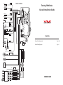
GREEN/BLACK (-)
WIRING DIAGRAM
REAR L
Touring 7500 Series
GREEN (+)
WHITE/BLACK (-)
General Installation Guide
FRONT L
GREY/BLACK (-)
FRONT R
POWER SUPPLY
WHITE (+)
GREY (+)
PURPLUE/BLACK (-)
OPTIONAL MACHINE
PURPLUE (+)
REAR R
RED
+BATTERY
YELLOW
BLACK
BATT
GND
ACC
ACC
ACC
RED
BROWN
YELLOW
LIGHT SWITCH
ILLUM
NOT IN
USE
BATTERY
FUSE 15A
MIC
GND
BLACK
GPS
Contents
RADIO ANTENNA
BLUE/BLACK
BLUE/WHITE
ANT CONT
STOP / BRAKE SWITCH
P
R
N
D
2
1
GEAR SWITCH
BRAKE
BACK
BLUE
EXTERNAL
USB
AMP-C
AUDIO FRONT L OUT
RED
AUDIO FRONT R OUT
WHITE
AUDIO REAR L OUT
RED
AUDIO REAR R OUT
WHITE
AUDIO SUB L OUT
RED
AUDIO SUB R OUT
3
REAR SEAT
MONITOR
AND AUDIO
EXTERNAL AMPLIFIER
WHITE
YELLOW
WHITE
RED
iPod
ORANGE
REAR MONITOR
VIDEO OUTPUT
REAR MONITOR
AUDIO OUTPUTS
REVERSE
CAMERA
REVERSE CAMERA IN
General Installation guide
Page 1&2
General Wiring Diagram
Page 3
GENERAL INSTALLTION GUIDE
Connectivity
IMPORTANT!!!
Be sure to read this installation guide thoroughly prior to installation. If installation methods or non standard parts not specified in this installation manual
are used, accidents or injury may result. Professional installation is required for this system. VMS recommends installation to be completed by an
authorised VMS dealer. The customer should keep this manual after installation for future reference.
What’s In The Box
1
2
3
4
5
6
7
8
GPS antenna
1 x Main Unit
1 x Power connector (power, speakers, camera in)
1 x AV / iPod / USB connector
1 x GPS Antenna
1 x Microphone
1 x Micro to SD adaptor
1 x micro SD card
8 x Hexagonal mounting screws (M5 x 8)
Ensure the antenna has a clear view of the sky. Attach Antenna to dash
surface with double sided adhesive pad. (not provided)
Connect all wiring on the back of the head unit including:
• Power & Speaker Loom
• AV Loom
• GPS Antenna
• iPOD Cable / AUX cable
• Mini USB update cable
• Bluetooth Module
Refit radio fascia panel.
Radio Fascia Panel
Install unit Into Dash
GPS antenna
Factory Radio
Factory radio mounting brackets
Do not press front fascia buttons with force, they may dislodge.
Connect Ground Terminal on Battery
Re-connect the GND terminal on the main vehicle battery.
Before Starting?
Ensure connections at the rear of unit are secure with no pressure applied on
any connections. Excessive pressure may result in damaging the connection
lead or breaking the connection from the unit itself.
Functionality Test
Disconnect the GND from the main
vehicle battery.
To ensure the installation is successful and all functions of the system are
operational, drive the vehicle into an open area with a clear view of the sky
and turn the ignition to the on position.
Complete the following quality assurance checklist.
Remove transit screws from DVD
mechnism.
QUALITY ASSURANCE CHECKLIST
Powers on and off with ignition.
- Select a location that is at least 30 cms from the body of the unit,
otherwise the accuracy of the GPS will decrease.
- If installing the GPS antenna inside the vehicle, the installation location
& shape of the vehicle’s cabin can decrease the sensitivity and accuracy
of the GPS signal. Accuracy is generally lower and GPS lock times are
generally longer when the antenna is placed in the cabin.
Remove Factory Radio
Radio Fascia Panel
Scan and store both FM and AM radio stations.
Insert and eject CD/DVD.
iPOD connectivity.
iPOD functionality.
USB connectivity (to USB flash disk).
Bluetooth Microphone
Reverse Camera is operational.
Ensure the microphone is mounted securely.
Factory Radio
Factory radio mounting brackets
Mounting Bracket to Main Unit
A pillar
Hexagonal Screws
M5 x 8
Microphone
• Install the microphone and
microphone wire where it cannot
interfere while driving.
• Do not install microphone where it
can interfere with switches in the
vehicle.
• If installing into a vehicle equipped
with airbags, ensure all parts of the
microphone do not interfere with
airbag operation.
Bluetooth is operational.
System audio volume is operational.
BASS/TREBLE, FADE/BAL is operational.
Navigation is operational with GPS lock.
Check default settings.
Auto display GPS screen = OFF.
GPS Audio = ON.
iPOD = ON.
VMS Unit
Park Brake Connection (example)
Factory radio mounting bracket
Connect the BRAKE wire (BLUE / WHITE) on the power loom to the park
brake signal wire of the vehicle.
PLEASE NOTE: Some vehicles may require repositioning of the
factory mounting holes in order to align the unit properly with the
dash. In these cases, re-drill the mounting positions on the bracket.
REAR ENTERTAINMENT = ON.
CDC MULTIDISCS = ON.
BRAKE INSPECTION = ON.
REVERSE CAMERA = ON.
STEERING WHEEL BUTTON = ON.
Connect BRAKE wire
To maintain proper function the unit
body must be mounted at less than
30 degrees from horizontal. If the
angle is excessive, CD/DVD skipping
and improper ejection may be
experienced.
AUTO DIMMING = ON.
GPS COLD START = OFF.
Reverse Wire connection (example)
If fitting a reverse camera, connect the BACK wire (BLUE)
30 Degrees
Reverse Lamp
Connect BACK wire
STEERING WHEEL KEY = Matches the vehicle & SW functions
are operational.
WARNING!!!
• This system is designed for 12-volt DV operation,
negative grounded Vehicles only. Never install into a
24-Volt vehicle such as commercial trucks or diesel
vehicles with cold region specifications. If unsure,
contact the manufacturer of the vehicle.
• Do not place any plastic storage bags over a person’s
head. This may cause suffocation or death.
• Keep small parts such as screws and brackets out of
reach of children.
• Do not disassemble, rebuild or alter the product.
Sophisticated electronic components internally may
cause injury, fire or electric shock.
• When it is necessary to replace the fuse, always use
a fuse of the correct ratings (no. of amperes) Inappropriate fuses may cause a fire.
• Do not operate the product after experiencing a
problem. Doing so will cause further damage to the
product and may lead to fire, or electric shock.
If an abnormal situation occurs, such as foreign matter
entering the product or it comes into contact with liquids,
smoke or strange odors are emitted, power off the
product immediately and consult the dealer where the
product was purchased. Continued operation may
cause injury, fire or electrical shock.