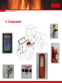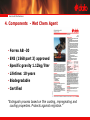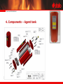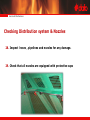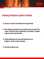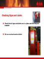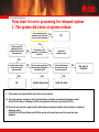
1
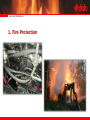
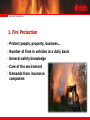
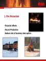
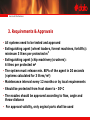
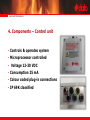
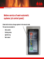
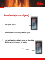
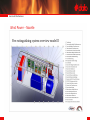
Service & Maintenance FORREX Suppression system © Dafo Brand AB 2009. All rights reserved. Service & Maintenance CEO Administration Quality & Environment General Fire & Safety Products Fire & Rescue Equipment Design Dept CAD Fixed Installations Training & Service Service & Maintenance Service & Maintenance Service & Maintenance Agenda 1. Fire protection 2. Function 3. Requirements & Approvals 4. Components 5. Service & Maintenance 6. Recharge 7. Handover Service & Maintenance 1. Fire Protection FROM: TO: Service & Maintenance 1. Fire Protection • Protect people, property, business… • Number of fires in vehicles at a daily basis • General safety knowledge • Care of the enviroment • Demands from insurance companies Service & Maintenance 1. Fire Protection • Financial effects • Secure Production • Reduce risk of business interruption Service & Maintenance 2. Function • Custom made, using proven components, meets demands of authorities and insurance companies • Manual, semi automatic or fully automatic systems • Dafo Forrex systems use a wet chemical which is easy to clean after activation • Operational temperature down to -30o C/-22 F • System size from 5 up to 200 liters • 6 different agent tank sizes • Can be combined with CO2 systems Service & Maintenance Service & Maintenance 2. Function • In case of a fire the system will make visual and audible alarm • The driver can actuate the system manually if needed • When actuated (manually or automatically) the agent tank will be pressurized from the cartridge and the agent will be distributed through the pipeline and the nozzles to the protected area • Release time appr. 20-40 seconds • Extinguish the fire usually in 1 second Service & Maintenance 3. Requirments & Approvals • FK 127:2011-4(fin) SBF127(swe) • ECE 10.3 EU standard for vehicles in traffic • TÜV / VDS • Russia N 123-03 • EN 60529 • EN 60068-2-64 • EN 10305 • EN 853 • 97/23/EY • FM (expected in March 2013) Service & Maintenance 3. Requirements & Approvals • All systems need to be tested and approved • Extinguishing agent (wheel loaders, forrest machines, forklifts): minimum 3 liters per protected m3 • Extinguishing agent (chip machinery/crushers): 6 litres per protected m3 • The system must release min. 80% of the agent in 20 seconds (systems calculated for 3 litres/m3) • Maintenance interval every 12 months or by local requirements • Should be protected from frost down to - 30o C • The nozzles should be approved according to flow, angle and throw distance • For approval validity, only orginal parts shall be used Service & Maintenance 4. Components Service & Maintenance Forrex - makes the difference Service & Maintenance 4. Components - Wet Chem Agent • Forrex AB -30 • EN3 (1568 part 3) approved • Specific gravity 1.12kg/liter • Lifetime: 10 years • Biodegradable • Certified ”Extinguish process based on film coating, impregnating and cooling properties. Protects against reignition.” Service & Maintenance 4. Components – Agent tank • Type SV-K • Aluminum • Patented • Working pressure 20 bars • Sizes from 5 to 25 liters, can be multiplied • Un-pressurized • Horizontal or vertical positioning • Service and maintenance friendly Service & Maintenance 4. Components – Agent tank Service & Maintenance 4. Components – Release mechanism • 3 different versions; - mechanical - pneumatic/electric - mechanical/pneumatic/electric Service & Maintenance 4. Components – Release mechanism Service & Maintenance 3. Components – Cartrigde • Pressure vessel, handle with care! • Propellant – Nitrogen N2 • Pressure 124 - 145 bar • Different sizes • Pressure test every 10th year (EN pressure vessel directive) Service & Maintenance 4. Components – Distribution piping & Nozzles • Stainless steel 12x1mm • Total length of max. 20 meters • JIC connections • Number of nozzles depends on agent tank volume (see design manual) Service & Maintenance 4. Components – Detection • Two (2) options; *spot detection *linear detection • Temperature range from 60-186o C/140-366 F • Supervised circuit • Number and/or type of detection will be chosen based on the protected area (see design manual) Service & Maintenance 4. Components – Control panel • Located in cabin or protected area • 5 leds indicates system status • Two (2) push buttons *Activate system *Test/Reset • Protective cover over actuation button • Different lanquage options Service & Maintenance 4. Components – Control unit • Controls & operates system • Microprocessor controlled • Voltage 12-30 VDC • Consumption 25 mA • Colour coded plug-in connections • IP 69K classified Service & Maintenance 5. Service & Maintenance Service & Maintenance 5. Service & Maintenance - Safety Warning! During service, use personal safety protection goggles Warning! Cartrige are high pressured cylinder, handle with care Caution! Pressure vessels (cartridge) must always be handled with the protective cap installed Caution! Before any welding, and/or auxiliary start-up, the control unit must be disconnected Caution! Service must be followed in the consecutive order, according to the test protocol and service instructions Service & Maintenance 5. Service & Maintenance - Safety Note! Service and repairs may only be performed by authorized personnel using parts and equipment for the applicable system Note! Some service action will activate alarms Note! Testing of system may only be performed by test unit Note! Secure safe working conditions Service & Maintenance Before service of semi-automatic systems (at control panel) Check which devices change system to the manual mode This can be connected to: - Main switch - Parking brake - Ignition key - Seat sensor Service & Maintenance Before Service (at control panel) 1. Check green LED is on 2. Switch system to manual mode (if that is an option) 3. Press Test/Reset button at least 1 second and check that all LEDs ligth up and the fire alarm will activate Service & Maintenance Checking function of control unit 1. Disconnect the connector from actuator (squib) cable. Disconnect the detector cable connector (blue) from the control unit 2. Check control panel that ”fault detector” and ”fault actuator” LEDs are on 3. Connect test unit cables to the control units cable in following order: - Blue connector to control unit´s connection (blue ring) - Blue connector to detector cable´s connection - Test unit connector to actuator (squib) cable - If needed use adaptercable (pn. 55-1742-02) Service & Maintenance Checking function of control unit 4. Check that LEDs for ”fault actuator” and ”fault detector” are NOT activated on the control panel. 5. Connect multimeter to test unit and measure resistance in the circuit. The resistance should be 1.8 kohm (double detection line 2x5.6kohm=2.8kohm) Check that there are no connection between either pole and ground of the machine 6. Press the test unit´s button at least 1 second to check function of the system. One of the two red LEDs on the test unit should flash. On the control panel green LED ON should be on and red LED ”Fire Alarm” should flash. Service & Maintenance Checking function of control unit 7. Reset system with TEST/RESET button on the control panel 8. Push activation button (red) at least 1 second and check that the red LED on test unit will activate. Reset by pushing green TEST/RESET button. 9. Disconnect red connector for five (5) seconds and reconnect it. Check control panel that only green LED is on 7. Close the protective cover on the control panel and seal it Service & Maintenance Checking and Inspection of Agent Tank 11. Inspect agent tank visually for any damage. Damaged tank shall be replaced. The agent tank is marked with manufacturing year and volume. At an age of 10 years, revision of tank should be performed (see recharge and revision instruction). Service & Maintenance Checking and Inspection of Agent Tank 12. Remove the outlet hose connection from top of tank. 13. Check that burst disc is not damaged and is leakage free. Service & Maintenance Checking and Inspection of Agent Tank 14. Disconnect propellant gas hose at the bottom of the agent tank and check that agent does not flow out and there is no leakage. Note; a small amount of agent may remain after filling. Service & Maintenance Checking Nitrogen cartrigde and Release Mechanism 15. Remove Nitrogen cartrigde and release mechanism by loosening the hoses and clamps 16. Unscrew cartrigde from release mechanism and install protection cap NOTE: protection cap should always be installed when cartridge is handled 17. Check that weigth of cartrigde corresponds to the weigth stated on the label. Max, deviation is – 14 grams. The cap weigth is 20grams and should be added to cartridge weigth. Service & Maintenance Checking Nitrogen Cartrigde and Release Mechanism 18. Dismantle the release mechnism. Clean and lube the gaskets with waterproof vaseline 19. Assemble the release mechanism 20. Check the level of the puncture pin tip. The measurement shall be in line with sliding calibers +/- 1 mm from the egde of mechanism Service & Maintenance Checking Nitrogen Cartrigde and Release Mechanism 21. Check the level of the puncture pin tip. The measurement shall be in line with sliding calibers +/- 1 mm from the egde of mechanism. 22. Check that pulling pin (yellow) is unbroken and put a new tag on it. Service & Maintenance Checking Detection circuit 23. Visually inspect the detectors/detectionline for any damage. In case of damages, replace items 24. Check that at all detectors or linear detector are clean , clean it Service & Maintenance Checking Detection circuit 25. Check that all connections are tight and corrosion free, replace if necessary.( Note; secure that all connectors are tight and that all washers under clamps will be at place.) 26. Clean and check that O-rings are damage free, lube it with waterproof vaselin. 27. If system equipped by linear detection , check that minimiun radius is not exceeded NOTE; Checking function of control unit also confirm operational condition of detection circuit. Service & Maintenance Checking central unit CV-01 BK Addition while using spot detector type BD-P Using spot detector type BD-P Connect multimeter with the buzzer connected. Heat a detector at a time and check that the buzzer on the multimeter is activated. All detectors shall be tested. NOTE! Cigarette lighters can not be used! Check that all detectors are free from any damage and that clamps are mounted on the wire. Service & Maintenance Checking Detection circuit Detector must be dust free Spot detector installation need to be complete with all washers Minium radius for linear detection wire Note; see installation manual Service & Maintenance Checking Distribution system & Nozzles 28. Inspect hoses , pipelines and nozzles for any damage. 29. Check that all nozzles are equipped with protective caps Service & Maintenance Checking Distribution system & Nozzles 30. Connect air hose to the outlet hose from agent tank 31. Start blowing and check that all protective caps comes off from nozzles. Check that flow is satisfactory in all nozzles. If needed, remove nozzles and clean them. 32. Follow distribution line and check that there are no leakage or cracks on hoses and pipes 33. Reinstall protective caps Service & Maintenance Checking Signs and Labels 34. Check that all signs and labels are in a place and that they are readable 35. Put on an actual service sticker Service & Maintenance Finishing 36. Fill in service protocol, give copy to the machine owner 37. Check that safety pin and control panel are affixed by seal 38. Check that control panel green LED is on Service & Maintenance Flow chart for error processing for released system 1. The system did alarm at system release Is it possible that the machine could have had a fire or been overheated Is there a red LED flashing/lit on the printed circuit board in the control unit Yes OK No Yes Is the value of the recistance in the detector circuit ok No Repair the detector circuit No Is the cable between the control unit and the alarm panel ok Yes Has the release button on the alarm panel been activated Yes OK 1: No Has the alarm panel been mechanically damaged or exposed to water Yes Switch alarm panel No See point 1: check list Yes Swith the cable If the system has released with an alarm there are two options: 1:1 The control unit has recieved an alarm from the detector circuit due to mechanical damages or moist. On the CV-01 B there is a flashing red LED on the printed circuit board (not valid for CV-01 A). 1:2 The control unit recieves a signal from the cable between alarm panel and the control unit due to mechanical damage or moist. On the CV-01-A/B there flashing red LED if the control unit has not been reset (the power has been disabled). Service & Maintenance Flow chart for error processing for released system 2. The system did not alarm at system release Is the ”Fault container” LED lit Yes Is the cable to the gas generator ok Yes See point 2 in the check list No Is the gas generator released No Yes Is the nitrogen cartridge released (check weight) No The burst disc has been activated Yes Is there any traces of water or oxides in the control unit A manual release has been performed Yes Change the control unit No Is the cable to the gas generator ok, check for damages 2: If the system has released without any alarm there are two options: 2:1 An electronic spike has occured in the system. A flash-over in the system though the gas generator has occured. Chech taht there is a plastic adaptor between the release mechanism and the gas generator 2:2 The cable to the gas generator is damaged and there has been a short circuit. (The system uses constant plus-feed and the outputs is controlled by minus-feed.) Service & Maintenance Replacement Intervals • Actuator (squib) 5 years, from installation date • Forrex agent 10 years, from filling date • Cartridge 10 years or according to local regulations • Sealings in agent tank 10 years • O-rings & sealings in release mechanism 10 years Service & Maintenance 6. Recharge - after system activation Service & Maintenance 6. Recharge - after system activation 1. Check out reason for system activation 2. Unplug actuator cable from control unit (green) 3. Remove the outlet hose connection from top of agent tank Service & Maintenance 6. Recharge - after system activation 4. Clean distribution pipeline with water, let water run through 5. Connect compressed air to outlet hose (dry air) 6. Blow distribution pipeline clean with compressed air for appr. 30 seconds until no fluid comes out from nozzles. 7. Install the caps on the nozzles 8. Clean engine compartment Service & Maintenance 6. Recharge - after system activation 9. Check if the system is damaged (see service instruction) 10. Repair or replace any equipment that has been damaged Service & Maintenance 6. Recharge - after system activation 11. Remove the adapter from the tank and clean it 12. Remove the broken burst disc 13. Disconnect propellant gas hose at the bottom of the agent tank Service & Maintenance 6. Recharge - after system activation 14. Disconnect agent tank from brackets (if neccassery) 15. Inspect agent tank for a any damage 16. Press back piston to bottom with compressed air Check distance from top to pistons (see instruction manual) No any mechnical devices inside cylinder Service & Maintenance 6. Recharge - after system activation 19. Fill the tank by Forrex AB-30 agent. Use a funnel with a hose in the end that reches to the bottom of tank, this will prevent the agent from ”foaming”. Fill it slowly. NOTE; The agent tank should be 100% full of liquid Service & Maintenance 6. Recharge - after system activation Refilling tool 59-3000-20 - Easy to use - Less foaming Service & Maintenance 6. Recharge - after system activation 20. Install new burst disk , installed with convex side up 21. Tighten the adaptor. Torgue 40Nm Note ; Lubricate the treads with grease. 22. Fill in signs with refill(recharge) date. 23. Install the agent tank. 24. Connect propellant gas hose at the bottom of agent tank. Note: If the agent tank is older than 5 years , change seals (see instructions) Service & Maintenance 6. Recharge - after system activation 25. Expose the expellant gas cartrigde and actuator by loosening hoses and clamps. Spin off the expellant gas cartridge from the actuator and install the protective nut 26. Dismantle the actuator. Clean and lube the gaskets with vaseline 27. Assemble the actuator 28. Check the pins level. The measurement shall be in line with sliding puncturing pin +/- 1 mm from the egde of mechanism is accepted Service & Maintenance 6. Recharge - after automatic activation 1. Replace actuator (squib). Tighten by hand only 2. Check adaptor for damages ( black, plastic) Service & Maintenance 6. Recharge - after system activation 29. Replace expellant gas cartrigde. Check that it is fully pressurized by weighing it. Correct weigth is stated on the label. Max. deviation from the weight is – 14 grams. The cap weight is 20 grams and should be added to total weigth Service & Maintenance 6. Recharge - after system activation 30. Assemble release mechanism to cartrigde 31. Connect hose to realese mechanism 32. Assemble cartridge to bracket Service & Maintenance 6. Recharge - after system activation 33. Follow system function checking procedure 34. Fill in service protocol, give a copy to the machine owner. 35. Check that pulling pin and control panel are equipped by seal 36. Check that control panel green LED is on Service & Maintenance 7. Hand over A final check must be carried out in accordance with the instructions in the ”Check list of Forrex installations for machines” document Make sure that driver/owner are aware of fire system function Check if the machine is equipped with user manual Service & Maintenance 7. Compressor for Atlas Copco Central typ CB-02 Forrexbehållare 25 liter Flamdetektor Rörsystem m munstycken Drivgaspatron Tillsats huvudbrytare Linjedetektor Manuell utlösning Service & Maintenance Compressor Atles Copco System Layout Service & Maintenance Wind Power - Nacelle Service & Maintenance