1
Rearview Camera
HCE-C105
• OWNER'S MANUAL
Please read before using this equipment.
• MODE D'EMPLor
Veuillez lire avant d'utiliser cet appareil.
• MANUALDEOPERACrON
Ualo antes de utilizar este equipo.
ALPINE ELECTRONICS MARKETING, INC.
1-1-8 Nishi Gotanda,
Shinagawa-ku,
Tokyo 141-0031, Japan
Phone 03-5496-8231
ALPINE ELECTRONICS OF AMERICA, INC.
19145 Gramercy Place. Torrance,
California 90501, U.S.A.
Phone 1-800-ALPINE-1 (1-800-257-4631)
ALPINE ELECTRONICS OF CANADA, INC.
777 Supertest Road, Toronto,
Ontario M3J 2M9, Canada
Phone 1-800-ALPINE-1 (1-800-257-4631)
ALPINE ELECTRONICS OF AUSTRALIA PTY. LTD.
161-165 Princes Highway, Hallam
Victoria 3803, Australia
Phone 03-8787-1200
ALPINE ITALIA S.p.A.
Viale C. Colombo 8, 20090 Trezzano
Sui Naviglio (MI), Italy
Phone 02-484781
ALPINE ELECTRONICS GmbH
Frankfurter Ring 117, 80807 Munchen, Germany
Phone 089-32 42 640
ALPINE ELECTRONICS DE ESPANA, SA
Portal de Gamarra 36, Pabell6n, 32
01013 Vitoria (Alava)-APDO 133, Spain
Phone 945-283588
ALPINE ELECTRONICS OF U.K. LTD.
Alpine House
Fletchamstead Highway, Coventry CV4 9TW, U.K.
Phone 0870-33 33 763
ALPINE ELECTRONICS FRANCE SAR.L.
(RCS PONTOISE B 338 101 280)
98, Rue de la Belle Etoile, Z.1. Paris Nord II,
B.P. 50016, 95945 Roissy Charles de Gaulle
Cedex, France
Phone 01-48638989
ALPINE ELECTRONICS (BENELUX) GmbH
Leuvensesteenweg 510-B6,
1930 Zaventem, Belgium
Phone 02-725-1315
Designed by ALPINE Japan
Printed in China (Y)
68-12118Z91-A
M3514382010
Operating Instructions
English
6
WARNING
This symbol means important
instructions. Failure to heed them can
result in serious injury or death.
MAKE THE CORRECT CONNECTIONS.
HALT USE IMMEDIATELY IF APROBLEM APPEARS.
Failure to make the proper connections may result in fire or
product damage.
Failure to do so may cause personal injury or damage to the
product. Return it to your authorized Alpine dealer or the
nearest Alpine Serviee Center for repairing.
USE THIS PRODUCT FOR MOBILE 12V APPLICATIONS.
Use for other than its designed application may result in
fire, electric shock or other injury.
WHEN REVERSING THE CAR, CHECKING BEHIND AND
AROUND THE CAR MUST BE DONE VISUALLY BY THE
DRIVER.
CHECK THAT THE CAMERA MOUNTING BRACKET IS
ATTACHED SECURELY, AND THAT THE SCREWS ARE TIGHT
BEFORE DRIVING.
The rearview camera assists the driver in checking behind
by sending images to the screen showing conditions behind
the car. The camera uses a wide-angle lens, therefore, there
is a difference in distance perspective between what is
normally seen and what appears on the screen. Also, the
images shown by the camera are reversed, so as to appear
the same as what is seen through the rearview mirror.
Failure to do so may result in an accident.
WHEN INSTALLING THE CAMERA, OR WHEN CHECKING IT
IS INSTALLED SECURELY, DO SO AFTER PARKING THE CAR
IN ALEVEL, SAFE PLACE, TURNING OFF THE ENGINE, AND
APPLYING THE HAND BRAKE.
Failure to do so may result in an accident.
Doing so may result in an accident, fire or electric shock.
WHEN USING ADRILL TO MAKE A HOLE, TAKE
PRECAUTIONS SUCH AS WEARING GOGGLES SO
FRAGMENTS DO NOT GET INTO THE EYES.
KEEP SMALL OBJECTS SUCH AS SCREWS OUT OF THE
REACH OF CHILDREN.
Failure to do so may result in injury.
DO NOT DISASSEMBLE OR ALTER.
Swallowing them may result in serious injury. If swallowed,
consult a physician immediately.
USE THE CORRECT AMPERE RATING WHEN REPLACING
FUSES.
Failure to do so may result in fire or electric shock.
USE ONLY IN CARS WITH A12 VOLT NEGATIVE GROUND.
kh CAUTION
This symbol means important
instructions. Failure to heed them can
result in injury or material property
damage.
(Check with your dealer if you are not sure.) Failure to do
so may result in fire, etc.
HAVE THE WIRING AND INSTALLATION DONE BY EXPERTS.
BEFORE WIRING, DISCONNECT THE CABLE FROM THE
NEGATIVE BATTERY TERMINAL.
The wiring and installation of this unit requires special
technical skill and experience. To ensure safety, always
contact the dealer where you purchased this product to have
the work done.
Failure to do so may result in electric shock or injury due to
electrical shorts.
DO NOT USE BOLTS OR NUTS IN THE BRAKE OR STEERING
SYSTEMS TO MAKE GROUND CONNECTIONS.
Bolts or nuts used for the brake or steering systems (or any
other safety-related system), or tanks should NEVER be
used for installations or ground connections. Using such
parts could disable control of the vehicle and cause fire etc.
DO NOT DAMAGE PIPE OR WIRING WHEN DRILLING
HOLES.
When drilling holes in the chassis for installation, take
precautions so as not to contact, damage or obstruct pipes,
fuel lines, tanks or electrical wiring. Failure to take such
precautions may result in fire.
ARRANGE THE WIRING SO IT IS NOT CRIMPED OR
PINCHED BY ASHARP METAL EDGE.
Route the cables and wiring away from moving parts (like
the seat rails) or sharp or pointed edges. This will prevent
crimping and damage to the wiring. If wiring passes
through a hole in metal, use a rubber grommet to prevent
the wire's insulation from being cut by the metal edge of
the hole.
USE SPECIFIED ACCESSORY PARTS AND INSTALL THEM
SECURELY.
Be sure to use only the specified accessory parts. Use of
other than designated parts may damage this unit internally
or may not securely install the unit in place. This may cause
parts to become loose resulting in hazards or product
failure.
EXCEPT FOR THE REARVIEW CAMERA ITSELF, DO NOT
ATTACH ANY PARTS TO AREAS WHICH WILL GET WET, OR
WHERE THERE IS ALOT OF HUMIDITY OR DUST.
Failure to do so may result in fire or damage.
DO NOT ATTACH THE CAMERA MOUNTING BRACKET TO
FLUOROCARBON RESIN FINISHED CAR BODIES OR
GLASS.
Doing so could cause the strength of the camera mounting
bracket to weaken, which could cause it to fall of and cause
accidents, injury, or damage to the car body.
DO NOT ATTACH THE CAMERA MOUNTING BRACKET TO
ANY SURFACE WHERE THE ENTIRE ADHESIVE SURFACE
CANNOT BE APPLIED.
Doing so could cause the strength of the camera mounting
bracket to weaken, which could cause it to fall of and cause
accidents, injury, or damage to the car body.
6
PRECAUTIONS
Do not assert any excess pressure to the camera or the mounting.
as this could cause the camera direction to shift, or the camera
mounting bracket to come off.
To prevent the camera lens, mounting and cords from changing
color or shape, or from deteriorating, wipe with a chemical-free.
damp cloth.
When washing the car, do not using an automatic car washer, or
high-pressure washer. Doing so could cause the camera to come
off, damage to the camera cord. or may allow water to enter the
camera or the inside of the car.
Be sure to disconnect the cable from the (-) battery post before
installing your HCE-C105. This will reduce any chance of
damage to the unit in case of a shon-circuit.
Be sure to connect the color coded leads according to the
diagram. Incorrect connections may cause the unit to malfunction
or damage to the vehicle's electrical system.
When making connections to the vehicle's electrical system, be
aware of the factory installed components (e.g. on-board
computer). Do not tap into these leads to provide power for this
unit. When connecting the HCE-C I05 to the fuse box. make sure
the fuse for the intended circuit of the HCE-C I05 has the
appropriate amperage. Failure to do so may result in damage to
the unit and/or the vehicle. When in doubt, consult your Alpine
dealer.
in some cases, to attach the camera, a hole must be drilled in the
car body, requiring use of touch-up paint (retail product) for rustprevention. and should be prepared beforehand.
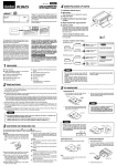
Installation/lnstallation/lnstalacion
Check Accessory PartsNerifiezlesac~essoife$lCQrnpruebelos accesorios
x2
CD Camera (O.5m)
CD Camera (O,5m)
CD Camara (O,5m)
®
®
®
@ Power unit (Reversel
ACC/GND: 1m)
@ Bloc d'alimentation
(Reverse/ACC/GND : 1m)
@ Unidad de alimentacion
(Marcha atras/ACCI
TIERRA: 1m)
®
®
Hexagonal wrench
Cle hexagonale
L1ave hexagonal
®
@ Camera mounting bracket
@ Support de la camera
@ Soporte de la camara
@ Hex screw
@ Vis a tete
hexagonale
@ Tornillo hexagonal
RCA extension cable (5m)
Cable rallonge RCA
(5 metres)
Cable de extension RCA
(5 m)
(f) ACC connection
cable (6m)
(f) Cable de connexion
ACC (6m)
(f) Cable de conexion
ACC (6m)
I
xS
® Waterproofing pad
®
®
Protege-cables
impermeable
Dispositivo protector
resistente al agua
®
®
®
Waterproofing pad adhesive
sheet
Adhesif pour protege-cables
impermeable
Hoja adhesiva para el
dispositivo protector
resistente al agua
@J Wire clamp
@J Attache-fils
@J Fijador de cables
x4
@ Velcro fastener
@ Bande velcro
@ Fijador de velcro
@ Self-tapping screw
@ Vis autotaraudeuse
@ Camera extension
@ Tornillo macho
@ Cable rallonge de la
roscador
cable (3.5m)
camera (3,5m)
@ Cable de extension de
la camera (3,5m)
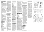
Installation LocationJEmplacement de l'installation/Ubicaci6n de la instalaci6n
Install the Camera on the Rear Bumper/lnstallez la
camera sur la carrosserie arrierel1nstalacion en el
acabado trasero
3 Faites un trou de 13 mm dans la carrosserie arriere
pour fixer Ie support de la camera (schema 2).
4 Faites passer Ie cable de la camera
vehicule par Ie trou fait I'etape 3.
a
a I'interieur du
5 Retirez Ie film protecteur du support de la camera,
puis fixez ce dernier sur Ie chassis du vehicule. Le
cas echeant, fixez Ie support I'aide des vis
autotaraudeuses.
Installing the Power Unit/1nstallation du bloc
d'alimentation/lnstalacion de la unidad de
alimentacion
Bottom of power unit!
Sous de bloc
d'alimentationl
Parte inferior de unidad
de alimentacion
a
Fig.lISchema l/Fig.]
Fig.2JSchema 2IFig.2
English
2
3
4
5
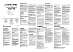
Attach the camera to the camera mounting bracket
@. Pull the camera cable through to the camera
mounting bracket @ , and secure with the hex
screws@ (see Fig. 1).
Loosen the camera mounting bracket @ and angle
adjustment screw. Determine the attachment angle,
and carefully tighten the angle adjustment screw.
Make a 13 mm hole in the rear bumper camera
mounting bracket (see Fig. 2).
Pull the camera cable inside the car through the
hole made in step 3.
Peel off the adhesive seal from the camera mounting
bracket and attach the camera mounting bracket on
the chassis of the vehicle. If required, fix the camera
mounting bracket using self-tapping screws.
• Attach the camera in a position where it does not touch
the number plate.
• Use retail touch-up paint to paint the surface and
sunvunding area when a hole has been made in a metal
surface.
• WaterplVof securely the hole made for the camera cable
using a commercially-available waterproof rape or
sealing material.
• If necessary, use a self-tapping screw @ to fix the camera
mounting bracket (In the case of a plastic mount area).
Fran~ais
Fixez la camera sur Ie support @. Passez Ie cable
de la camera dans Ie support @, puis fixez-Ie
I'aide des vis hexagonaux @ (schema 1).
2 Deserrez Ie support de la camera @ et inserez en
angle la vis de reglage. Choisissez I'angle de
fixation, puis reserrez delicatement la vis dans cet
angle.
a
• Fixez la camera de faron a ce qu'elle ne touche pas la
plaque d'immatriculation.
• Si vous avez perce un tlVU dans une surface merallique,
une retouche est necessaire sur et autour de la surface
avec une peinture speciale.
• Les passes-fils a l'interieur du vehicule doivent etre
impermeables .. pour cela, utilisez du ruban adhesif
impermeable ou un autre plVduit d'etancheite vendu
dans Ie commerce.
• Si besoin est, utilisez une vis autotaraudeuse @ pour
fixer Ie support de la camera (notamment si la surface de
montage est en plastique).
Espanal
2
3
4
5
Coloque la camara en el soporte de la camara @.
Tire del cable de la camara a traves del soporte de
la camara @ y !fjelo con los tornillos hexagonales
@ (vease la figura 1).
Afloje el soporte de la camara @ e inserte en
angulo el tornillo de ajuste. Calcule el angulo de
fijaci6n y, con cuidado, apriete el tornillo en dicho
angulo.
Realice un agujero de 13 mm en el soporte de la
camara del acabado trasero (vease la figura 2).
Tire del cable de la camara desde el interior del
coche a traves el agujero del paso 3.
Retire el sello adhesivo del soporte de la camara y
!fjelo en el chasis del vehfculo. Si fuera necesario,
fije el soporte de la camera con ayuda de los
tornillos embriados suministrados.
• Coloque la camara en una posicion en la que no toque la
matricula.
• Utilice pintura para retocar la superjicie y el area que
rodea el agujero realizado en la superficie de metal.
• Para garantizar que las arandelas aislantes colocadas
en el interior del vehiculo son resistentes al agua, utilice
cinta adhesiva resistente al agua 0 algun tipo de
material sellante.
• Si es necesario, utilice un tornillo macho roscador @
parafijarel soporte de la camara (en caso de que el
area de instalacion sea de pldstico).
Velcro fastener (hard side)!
Sande velcro {e6te
rugueux)fFijador de velcro
(cara dura)
Hg. 61Schema 6/Fig. 6
English
Attach the Velcro fastener (hard side) @ to the
bottom of the power unit @ (see Fig. 6).
2 Attach the Velcro fastener (soft side) @ to the floor,
and secure the power unit@.
• When attaching the Velcro fastener (hard side) @ to the
floor carpet, do so without the Velcro fastener (soft side)
@attached.
Fran~als
Fixez la bande velcro (cote rugueux) @ sous Ie
bloc d'alimentation @ (schema 6).
2 Fixez la ban de velcro (cote doux) @ au sol, puis
attachez Ie bloc d'alimentation @.
• Lorsque vousfixez la bande velcro (cote rugueux)@au
sol, fixez-ta sans decoller Ie cote doux de ta bande velcro
@.
Espanal
Coloque el fijador de velcro (cara dura) @ en la
parte inferior de la unidad de alimentaci6n @
(vease la figura 6).
2 Coloque el fijador de velcro (cara blanda) @ en el
suelo y fije la unidad de alimentaci6n @.
• Al colocar elfijador de velcro (cara dura) @ en la
moqueta del suelo, hdgalo sin despegar la cara blanda
del velcro @.
Connections/Raccordements/Conexiones
Fran,,:ais
N°
------------
Nom
--_._--,
Couleur du Caracteristiquel
connecter fonction
~L.PINE
I
[I]
Connecteur de
sortie video
---
m
Connecteur de
la camera arriere
---
rn
Fusible
---
[!]
lID
Fil Reverse/ACC
Conducteur de
terre
Name
Lead
color
Specificationl
Function
Connect to
Outputs a camera
Connect the RCA
extension cable
(included), and
then to the camera
video input
connector of the
connected device.
video on the
[I]
m
rn
[!]
ffiJ
Video Output
Connector
Rear Camera
Connector
---
connected monitor
or navigation
system.
---
Inputs the rear
camera video
signal.
Fuse
---
Reverse/ACC
When reversing
the vehicle, the
Orangel lead is used to
white
supply power to
the unit.
Lead
Ground Lead
Black
Connect the
camera extension
cable to the rear
camera.
Fix the lead
securely to a metal
part of the car's
chassis.
Connect the lead
securely to a metal
part of the car's
chassis. Failure to
do so may cause a
malfunction.
• Install the camera cable and RCA extension cable wiring
away from the radio antenna and antenna cable. If they
are too close, or wrapped together, noise can result.
Diffuse Ie signal
Connectez Ie cable
rallonge de la
camera a la
camera arriere.
video de la
7,5A
Fixez ce
connecteur
correctement a un
ele rnent metallique
du chassis du
vehicule.
Connectez ce fil ala
borne positive de
I'alimentation du feu
arriere du vehicule, ou
placez la cle de contact
en position ACC.
Raccordez ce
connecteur correctement
aun element metallique
du chassis du vehicule.
Dans Ie cas contraire, un
dysfonctiopnnement
peut se produire.
• Installez Ie dible de la camera et Ie dible rallonge RCA
a l'ecart de l'antenne radio et du dlble d'antenne. S'ils
sont trop prets les uns des autres, des interferences
peuvent se produire.
Espanal
N.O
[I]
7.5A
Connect the lead
to the positive side
of the rear lamp
feed of the vehicle,
orthe ACC
position.
Raggordez-Ie au
cable rallonge RCA
(fourni), puis au
connecteur d'entree
video de la camera
du peripherique
connecte.
Lorsque vous
faites marche
Orangel arriere, ce fil est
blanc utilise pour
alimenter I'unite.
English
No.
Reproduit I'image
de la camera sur
Ie moniteur
connecte ou Ie
systeme de
navigation.
camera arriere.
Noir
Le raccorder a
Nombre
Conectorde
salida de video
Color del Especificaci6nl
cable
Funci6n
---
Emite la imagen
de la camera en el
monitor 0 en el
sistema de
navegaci6n
conectado.
Conecte el cable de
extensi6n RCA
(incluido) y, a
continuaci6n, el
conector de entrada
de la camera del
dispositive conectado.
recibe la senal de
Conecte el cable
de extensi6n de la
camera a la
camera trasera.
m
Conector de
camera trasera
---
video de la
rn
Fusible
---
7,5A
Cable Marcha
[!]
lID
atras/ACC
Cable de tierra
Conectar a
camera trasera.
Cuando el
vehiculo circula
Naranjal marcha atras, este
Blanco cable se utiliza
para alimentar la
unidad.
Conecte el cable al
borne positivo de
la alimentaci6n de
faros traseros del
vehiculo, 0 bien a
la posici6n ACC.
Fije el cable
correctamente a
una pieza metalica
del chasis del
vehiculo.
Conecte el cable
correctamente a una
pieza metalica del
chasis del vehiculo. Si
no 10 hace, la unidad
podria no funccionar
correctamente.
Negro
• Instale el cable de la camara y el cable de extension
RCA desde la antena de radio y el cable de la antena. Si
estan demasiado cerca 0 entrelazados, podian
producirse inteiferencias.
Adjusting the Camera Angle/Reglage de I'angle de la
cameralAjuste del angulo de la camara
Espanol
6
Precauci6n
Cuando ajuste el angulo de la camara, apague
primero el motor y ponga el freno de mana para
evitar posibles accidentes.
Ponga la palanca de marchas en marcha atras (R)
y compruebe la imagen de la camara que se
muestra en la pantalla.
2 Afloje el soporte de la camara @ e inserte en
angulo el tornillo de ajuste. Calcule el angulo de la
camara y, con cuidado, apriete el tornillo en dicho
angulo.
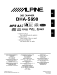
Securing the Camera Cable/Fixation du cable de la
cameraiFijaci6n del cable de la camara
English
Caution
When adjusting the camera angle, do so after turning
off the engine and applying the hand brake to avoid
an accident.
Put the gear shift into reverse (R), and check the
image from the camera on the display.
2 Loosen the camera mounting bracket @ and angle
adjustment screw. Determine the camera angle,
and carefully tighten the angle adjustment screw.
6
a
Fran4f:alS
Fixez Ie cable de la camera en vous reportant au
schema 7.
Fixez Ie protege-cables ® sur son ruban adhesif
®, puis fixez et tendez Ie cable sortant du protegecables ® I'aide de I'attache-fils ®.
• Assurez-vous que Ie ciible n'est pas coince dans la malle,
dans les portes arrii!res ou dans une chamii!re.
• Le dible doit etre hoI's des protections des chamii!res et
des hamais.
• Une fois Ie cablage termine, ouvrez et refermez plusieurs
fois la malle arriere et les portes arrieres afin de vous
assurez que Ie cable n 'est pas coince et qu 'il ne subit
aucun frollemelll.
Espanol
Fran~alS
Mettez Ie levier de vitesse en marche arriere (R),
puis verifiez I'image de la camera affichee I'ecran.
2 Deserrez Ie support de la camera @ et inserez en
angle la vis de reglage. Choisissez I'angle de la
camera, puis reserrez delicatement la vis dans
I'angle.
®.
• Ensure the cable does not get caught in the trunk, rear
door(s) or any hinges.
• The cable should go on the outside of car hinges and
hamess covers.
• After completing wiring, open and close the trunk and
the rear doors several times to confirm the cable is not
gelling caught or rubbing anywhere.
a
6
Attention
Veillez 11 couper Ie moteur et 11 mettre Ie frein 11 main
avant de regler "angle de la camera afin d'eviter tout
accident.
English
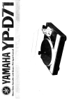
Secure the camera cable while referring to Fig. 7.
Attach the waterproof pad ® with the waterproof
pad adhesive sheet ®, and secure any slack cable
around the waterproof pad ® using the wire clamp
(A)
(8)
(C)
(D)
Rearview camera/Camera arriereJCamera trasera
To Power unitIBloc d'alimentationlUnidad de alimentaci6n
C1amper/Attache-fiLsIFijador
Waterproofing pad/Protege-cables impenneableIDispositivo protector
resistente al agua
Fig. 7/Schema 7/Fig. 7
Fije el cable de la camara siguiendo el diagrama de
la figura 7.
Coloque el dispositivo protector resistente al agua
® con la hoja adhesiva correspondiente ® y fije
cualquier cable que sobresalga alrededor del
dispositivo resistente al agua ® con ayuda del
fijador de cables ®.
• Verijique que el cable no queda atrapado en el maletero,
las puertas traseras 0 en cualquier bisagra.
• El cable debe estar fuera de las protecciones de las
bisagras y ameses del vehfculo.
• Una vezfinalizado el cableado, abra y cierre el maletera
y las puertas rraseras varias veces para comprobar que
el cable no queda atrapado ni plegado en ningun sitio.
Specifications/Specifications/Especificaciones
Output Drive Capacity
Image Sensor
Effective Number of Pixels
Lens Section
Angle 01 field
Aulomatic Image Adjusting Function
14.4V DC
Negative ground type
less than 2.4W
Mirror image, VBS (NTSC
Color signal system)
75 ohms
1/4 type color CCD image
sensor, aspect ratio 4 : 3
510 (horizontal) x 492 (vertical)
approximately 250,000 pixels
Focal length: f=1.28mm,
brightness: F=2.8
Horizontal: 138', Vertical: 105'
Automatic metering
adjustment, Automatic white
balance adjustment
Inlernal synchronization
40dB or more
300 lines
Approx. 1.51x to 100,000 Ix
Synchro-System
SIN ratio
Resolution (horizontal,cenler area)
lIIuminalion Range
Operaling Temperature Range
• Camera seclion
-30'C 10 +70'C
• Power section
-30'C to +60'C
External Dimensions (W x H x D)
• Camera section (except projection on the rear)
................................................................... 59/64" x 59/64" x 31/32"
(23.4mm x 23.4mm x 24.6mm)
• Power seclion (except projection)
................................................................... 3-15116" x 1-31/32" x 63/64"
(100mm x 50mm x 25mm)
Weight
• Camera section (including cable)
1-1/8 oz.
(37g)
• Power seclion (including cable)
6-1/2 oz.
(182g)
Espanol
Fran¥ais
English
Power Requirements
Ground Type
Power Consumption ...•..•..•.•....•.........•.....•...••
Output Image
Puissance requise
Type de masse
Consommalion d'energie
Image reproduite
Capacite d'excitation de sortie
CCD
Nombre effectif de pixels
Section de I'objeclil
14,4 V DC
Masse negative
moins de 2,4 W
Image miroir, VBS (systeme de
signaux couleur NTSC)
75 ohms
Capteur d'image CCD couleur
1/4", format d'image 4 : 3
510 (horizontal) x 492 (vertical),
environ 250.000 pixels
Focale: 1= 1,28 mm,
luminosite: F = 2,8
Horizontal: 138', Vertical :105'
Angle de champ
Fonction de reglage aUlomatique de l'image
......................................................................... Reglage automatique de la
mesure, Reglage automalique
de la balance des blancs
Systeme de synchronisation
Synchronisation interne
Rapport signal sur bruil
40 dB ou plus
Resolulion (horizontale,zone cenlrale)
300 lignes
Plage d'iIIumination
environ 1,5 100.000 Ix
Plage de lemperatures de lonclionnemenl
-30 a +70 'c
• Section de la camera
• Seclion d'alimentalion
-30 +60
Dimensions externes (I x H x P)
• Section de la camera
59/64" x 59/64" x 31/32"
(23,4 x 23,4 x 24,6 mm)
(partie saillante arriere non comprise)
• Seclion d'alimenlatlon
3-15/16" x 1-31/32" x 63/64"
(100 x 50 x 25 mm)
(partie saillanle non comprise)
Poids
• Section de la camera (cable compris)
1-1/8 oz.
(37g)
• Section d'alimenlation (cable compris) ....... 6-112 oz.
(182g)
a
a
'c
Requisitos de alimentacion
Tipo de toma de lierra
Consumo de energia
Imagen de salida
Capacidad de impulso de salida
Sensor de imagen
Numero electivo de pixeles
Seccion de lalente
14,4 V CC
Tipo toma de lierra negativa
menos de 2,4 W
Imagen en espejo, VBS (sistema
de senal a color NTSC)
75 ohmios
Sensor de imagen CCD de 1/4
pulg., relacion de aspecto 4 : 3
510 (horizontal) x 492
(vertical), aproximadamenle
250.000 pixeles
Longitud local: I = 1,28 mm,
brillo: F = 2,8
Horizontal: 138', Vertical: lOS'
Angulo de campo
Funcion de ajuste de imagen aulomatico
...................................................................... Ajuste de medlcion
automatico, ajuste automstico
del balance de blancos
Sistema de sincronizacion
Sincronizaci6n interna
Relacion senal-ruido
Como minimo 40 dB
Resolucion (horizontal, area central)
300lineas
aprox.de 1,5 a 100.000 Ix
Alcance de la iluminacion
Inlervalo de temperatura de luncionamiento
• Seccion de camara
-Entre 30 y +70'C
-Entre 30 y +60'C
• Seccion de alimenlacion
Dimensiones externas (ancho x alto x largo)
• Seccion de camara
59/64" x 59/64" x 31/32"
(23,4 x 23,4 x 24,6 mm)
(excepto proyeccion Irasera)
3-15/16" x 1-31/32" x 63/64"
• Seccion de alimentacion
(100 x 50 x 25 mm)
(excepto proyeccion)
Peso
• Seccion de camara (incluido cable)
1-1/8 oz.
(37g)
• Seccion de alimentacion (incluido cable) ...... 6-1/2 oz.
(182g)
ffffMLPINER
NotelRemarque/Nota
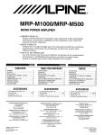
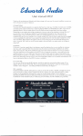
Special Instructions for Pickup Truck Installations I Instructions speciales pour installation sur un pickup Iinstrucciones especiales para las instalaciones en camionetas
t
Front of pickup truck!
Avant du pickup!
Parte delantera de la camioneta
Recommended camera power supply
mounting location (inside pickup cab)/
Emplacement de montage recommande
de I'alimentation de la camera
(3 I'interieur de la cabine du pickup)!
Ubicacion recornendada para colocar 141
fuentc de alimentation de la camara
(en el interior de la camioncta)
~ CAUTION
This symbol means important
instructions.
Failure to heed them can
result in injury or material
property damages.
Special Instruction #1
In pickup truck installations, the wire that
connects between the camera and the
camera power supply typically gets installed
under the pickup truck chassis.
-This wire must be protected from damage
using split-loom tubing in any areas where it
is installed under the pickup chassis.
-The rubber grommet where the wire passes
from the cab to the underside of the truck
must be sealed with silicone '0 prevent
moisture intrusion into the pickup truck cab.
Special Instruction #2
Rubber grommet to pass
camera wire from inside
of pickup truck cab to
underside of pickup truck
chassis/
Passe-c1oison en
caoutchouc pour faire
transiter Ie til de la
camera de I'interieur de
la cabine du pickup Yers
Ie dessous du chassis!
Arandela de goma para
power supply!
Recommended HCE-CI05 Back-up camer<:t
Connecteur blanc entre 13
camera arrierc et
l'alimentationf
Conector blanco entre la
camara de vision trasera )'
la fuentc de aHmentarion
mounting location (on rear humper)!
Emplacement de montage recommande de
)3 camera arriere HCE-CI05 (sur Ie parechoes arrieTc)/
Ubicacion recomendada para colocar la
camara de vision trasera HCE-CI05 (en el
parachoques trasero)
Instruction speciale n 0 1
~PRUDENCIA
Este simbolo indica que ias
instrucciones son importantes. De no tenerse en cuenta,
podria ocasionarse heridas
graves 0 danos materiales.
Instrucci6n especial n.°1
En cas d'installation sur un pickup. Ie fil qui
relie la camera a son alimentation est
generalement instal Ie sous Ie chassis du
vehicule.
-Le fil doit etre protege contre les degats au
moyen d'un tubage pour cablage, la ou il
est installe sous Ie chassis du pickup.
En instalaciones realizadas en camionetas,
el cable que conecta la camara y la fuente
de alimentaci6n de la camara normalmente
se instala bajo el chasis de la cam ioneta.
-Le passe -cloison en caoutchouc, utilise
pour acheminer Ie fil de la cabine vers Ie
dessous du pickup, doit etre protege avec
du silicone pour eviter toute intrusion
d'humidite dans la cabine du vehicule.
-La arandela de goma por el que pasa el
cable desde la cabina hasta la parte inferior
de la camioneta se debe sellar con silicona
para evitar la entrada de humedad en la
cabina de la camioneta.
Instruction speciale n02
-Este cable debe estar protegido mediante
un tubo de hendidura en espiral en las
zonas en las que se encuentre instalado
bajo el chasis de la camioneta.
Instrucci6n especial n.02
In pickup truck installations, the white
electrical connector between the back-up
camera and the camera's power supply may
be exposed to moisture. If so, it must be
sealed to prevent corrosion. This can be
accomplished in one of three ways:
En cas d'installation sur un pickup, Ie
connecteur electrique blanc situe entre la
camera arriere et son alimentation risque
d'etre expose a I'humidite. Si c'est Ie cas, il
doit etre protege afin d'eviter toute corrosion
Cela peut etre effectue de trois manieres
differentes :
En instalaciones realizadas en camionetas,
el con ector electrico blanco situado entre la
camara de visi6n trasera y la fuente de
alimentaci6n de la camara pod ria estar
expuesto a la humedad. En ese caso se
debe sellar para evitar la corrosi6n. Esto
puede Ilevarse a cabo de una de las tres
siguientes maneras:
Option #1)
Seal the white connector by
wrapping it tightly with good
quality electrical tape after
installation.
Option n01)
Protegez Ie connecteur blanc
en I'entourant convenablement
de bande isolante de bonne
qualite, une fois I'installation
terminee.
Opci6n n.01) Selle el con ector blanco
rodeandolo de cinta aislante
electrica de buena calidad
tras la instalaci6n.
Option #2)
Seal the white connector using
heat-shrink tubing.
Option n02)
Protegez Ie connecteur blanc avec
un tubage thermoretractrable.
Opci6n n.02) Selle el conector blanco
mediante un tubo termocontractil.
Option #3)
Apply dielectric white grease to
both sides of the white
connector before installation.
Option n03)
Appliquez de la graisse
blanche dielectrique aux deux
extremites du connecteur
blanc, avant son installation
Opci6n n03) Aplique lubricante blanco
dielectrico en ambos lados
del con ector blanco antes de
la instalaci6n.
pasar el cable de la
camara desde el interior
de la cabina de la
camioneta a la parte
inferior del chasis de la
camioneta
\Vhite connector between
back-up camera and
~ATTENTION
Ce symbole designe des instructions importantes.
Le non-respect de ces instructions peut entralner des
blessures au des dammages
materiels.
Printed in China (Y)
68-12118Z93-A
HCE-C105
M3544117010
~LPINE.
Customer Care Registration
. . . For easy on-line registration, go to ..www.alpine-usa.com/registration ..
Thank you for choosing Alpine! Please register your product with us so we can serve you better.
First name:
• Product purchased
Last name:
_
Home address: =St-ree~t-ad~dr-es.,..s- - - - - - - - - - -
City
State/Provo
Zip Code
May we contact you at this address? 1.0 Ves 2.0 No
Phone number: (
...:-_----------1.0Ves 2.0No
May we contact you at this number?
W
II:
W
::E:
...J
«
W
en
E-mail Address:
1.0 Male
t
_
_
Vear:
1.0 Single
4. 0 Asian
5.0 Other
=----
2.0 Married
_
.Your highest level of education completed:
1. 0 High School Student
2.0 High School Graduate
3.02 Vr. Degree/Some College
4.0 Completed 4 Vr. College
5.0 Completed Graduate School
Month:
_
Vear:
1.0 Alpine...., (Model No.)
_
---------------------
2.0 Other...., (Brand Name)
• Purpose of buying this unit?
1.0 Addition
2.0 Replacement...., *Previous brand replaced?
1.0 Factory installed
2.0 Alpine
3.0 Other
_
• Have you purchased Alpine products before?
1. 0 First time
Thank you for your cooperation! We value your privacy. This information will remain confidential with Aipine and its affiliates.
2. 0 Two or more times
_
• Which of the following statements best describes you?
_
• Serial Number:
2.0 No.
(Brand Name)
• If navigation system, which monitor?
.Which ethnicity best describes yourself:
1. 0 Caucasian
2.0 Hispanic
3. 0 African-American
1.0Ves
• Model Number:
1.0Ves 2.0No
2.0 Female
• Date of Birth Month:
• Marital Status
.When you purchased this Alpine unit, did you
compare it with other brands?
9. 0 Monitor Controller
10.0 Video Monitor
11 . 0 Navigation
12.0 Mobile Mayday
13.0 Video Tape Player
14.0 Processor/Equalizer
15.0 Security
16.0 Other
• Date of Purchase:
May we contact you bye-mail?
• Gender
1. 0 Cassette Player
2. 0 CD Player
3. 0 MD Player
4. 0 DVD Player
5.0 CD Changer
6.0 Amplifier
7. 0 Speaker
8. 0 Subwoofer
1.0 I usually have more electronic equipment than my friends
2. 0 I am usually one of the first of my friends to buy the newest
electronic equipment
3. 0 I usually wait until a product has been out for a while before
I purchase it
4.0 I am usually on of the first of my friends to know about the
newest car
5. 0 I usually know more about cars than my friends
• Occupation
1. ~ Executive/Managerial
2.
Secretarial/Clerical
3.
Sales
4.
General Labor
5.0 Professional
§
6.
EngineeringlTechnical
7.
Farming/Fishing
8.
Retired
9.
Student
10.0 Other
_
en
m
»
r::E:
m
m
:xl
• Household Income
1. 0 Less than $30,000
2.0 $30,000 - $50,000
3.0 $50,000 - $70,000
4.0 $70,000 - $90,000
5.0 $90,000 - $110,000
6.0 Over $110,000
• Type of vehicle in which this unit is installed.
Make:
Purchased Vear:
Model:
_
_
Model Vear:
_
• How was this vehicle purchased?
1.0 Bought
Customer Care Registration is for Product registration.
Failure to complete and return this card does not diminish your warranty rights.
2.0 Leased
PART NO. 68P04190K17-A
M3544084010
II I I
NO POSTAGE
NECESSARY
IF MAILED
INTHE
UNITED STATES
BUSINESS REPLY MAIL
FIRST·CLASS MAIL
PERMIT NO. 320
TORRANCE CA
POSTAGE WILL BE PAID BY ADDRESSEE
ATIENTION MARKETING SERVICES
ALPINE ELECTRONICS OF AMERICA INC
PO BOX 2859
TORRANCE CA 90509-9939
1111111111111111111111111111111111111111111111111111
r
FOR USE IN USA, PLEASE FOLD HERE AND ENSURE THAT
AMERICAN ADDRESS FACES UP.
°dn S38'v'::I SS3800'v' N'v'IO'v'N'v'8
1'v'H138nSN3 ON'v' 383H 010::1 3S'v'31d "v'O'v'N'v'8 NI 3Sn 80::1
1.
1111111111111111111111111111111111111111111111111111
VJICl3V\1V .::10 S3.LV.LS 03.LINn
9LB6-~0906 VJ 3JNVClClO.L
ld AJCl3V\1VCl8 9v~6~
SJINOCl.LJ313 3NldlV
)lAId lSNDdlU/11VW AldlU SS.-ll_INUU.
-
m 1III1G/SBI
mvlSOIM
-.Ill
IIMI:I
AMRIII
IIV. . . .
.:IIIVIHV IV~.
--
rnJmIm
I1III1
mm
/W#/ILPINEc~
LIMITED WARRANTY
ALPINE ELECTRONICS OF AMERICA, INC. AND ALPINE OF CANADA INC. ("Alpine"), are dedicated to quality craftsmanship and are pleased to
offer this Warranty. We suggest that you read it thoroughly. Should you have any questions, please contact your Dealer or contact Alpine at one of the
telephone numbers listed below.
• PRODUCTS COVERED:
.HOW WE LIMIT IMPLIED WARRANTIES:
This Warranty covers Car Audio Products and Related Accessories
("the product"). Products purchased in the Canada are covered only in
the Canada. Products purchased in the U.S.A. are covered only in the
U.S.A.
ANY IMPLIED WARRANTIES INCLUDING FITNESS FOR USE AND
MERCHANTABILITY ARE LIMITED IN DURATION TO THE PERIOD
OF THE EXPRESS WARRANTY SET FORTH ABOVE AND NO
PERSON IS AUTHORIZED TO ASSUME FOR ALPINE ANY OTHER
LIABILITY IN CONNECTION WITH THE SALE OF THE PRODUCT.
.LENGTH OF WARRANTY:
This Warranty is in effect for one year from the date of the first
consumer purchase.
.WHO IS COVERED:
This Warranty only covers the original purchaser of the product, who
must reside in the United States, Puerto Rico or Canada.
.WHAT IS COVERED:
This Warranty covers defects in materials or workmanship (parts and
labor) in the product.
.WHAT IS NOT COVERED:
This Warranty does not cover the following:
Damage occurring during shipment of the product to Alpine for
repair (claims must be presented to the carrier).
® Damage caused by accident or abuse, including burned voice coils
caused by over-driving the speaker (amplifier level is turned up and
driven into distortion or clipping). Speaker mechanical failure (e.g.
punctures, tears or rips). Cracked or damaged LCD panels.
Dropped or damaged hard drives.
@ Damage caused by negligence, misuse, improper operation or
failure to follow instructions contained in the Owner's manual.
@ Damage caused by act of God, including without limitation,
earthquake, fire, flood, storms or other acts of nature.
Any cost or expense related to the removal or reinstallation of the
product.
® Service performed by an unauthorized person, company or
association.
® Any product which has the serial number defaced, altered or
removed.
(}) Any product which has been adjusted, altered or modified without
Alpine's consent.
® Any product not distributed by Alpine within the United States,
Puerto Rico or Canada.
® Any product not purchased from an Authorized Alpine Dealer.
CD
.HOW TO OBTAIN WARRANTY SERVICE:
.HOW WE EXCLUDE CERTAIN DAMAGES:
ALPINE EXPRESSLY DISCLAIMS LIABILITY FOR INCIDENTAL AND
CONSEQUENTIAL DAMAGES CAUSED BY THE PRODUCT. THE
TERM "INCIDENTAL DAMAGES" REFERS TO EXPENSES OF
TRANSPORTING THE PRODUCT TO THE ALPINE SERVICE
CENTER, LOSS OF THE ORIGINAL PURCHASER'S TIME, LOSS OF
THE USE OF THE PRODUCT, BUS FARES, CAR RENTALS OR
OTHERS COSTS RELATING TO THE CARE AND CUSTODY OF THE
PRODUCT. THE TERM "CONSEQUENTIAL DAMAGES" REFERS TO
THE COST OF REPAIRING OR REPLACING OTHER PROPERTY
WHICH IS DAMAGED WHEN THIS PRODUCT DOES NOT WORK
PROPERLY. THE REMEDIES PROVIDED UNDER THIS WARRANTY
ARE EXCLUSIVE AND IN LIEU OF ALL OTHERS.
.HOW STATE/PROVINCIAL LAW RELATES TO THE
WARRANTY:
This Warranty gives you specific legal rights, and you may also have
other rights which vary from state to state and province to province. In
addition, some states/provinces do not allow limitations on how long an
implied warranty lasts, and some do not allow the exclusion or limitation
of incidental or consequential damages. Accordingly, limitations as to
these matters contained herein may not apply to you.
.IN CANADA ONLY:
This Warranty is not valid unless your Alpine car audio product has been
installed in your vehicle by an Authorized Installation Center, and this
warranty stamped upon installation by the installation center.
.HOW TO CONTACT CUSTOMER SERVICE:
Should the product require service, please call the following number for
your nearest Authorized Alpine Service Center.
CAR AUDIO
NAVIGATION
1-800-ALPINE-1 (1-800-257-4631)
1-888-NAV-HELP (1-888-628-4357)
Or visit our website at; http://www.alpine-usa.com
CD
You are responsible for delivery of the product to an Authorized
Alpine Service Center or Alpine for repair and for payment of any
initial shipping charges. Alpine will, at its option, repair or replace
the product with a new or reconditioned product without charge. If
the repairs are covered by the warranty, and if the product was
shipped to an Authorized Alpine Service Center or Alpine, Alpine
will pay the return shipping charges.
® You should provide a detailed description of the problem(s) for
which service is required.
@ You must supply proof of your purchase of the product.
@ You must package the product securely to avoid damage during
shipment. To prevent lost packages it is recommended to use a
carrier that provides a tracking service.
ALPINE ELECTRONICS OF AMERICA, INC., 19145 Gramercy Place, Torrance, California 90501, U.S.A.
ALPINE ELECTRONICS OF CANADA, INC., 777 Supertest Road, Toronto, Ontario M3J 2M9, Canada
Do not send products to these addresses.
Call the toll free telephone number or visit the website to locate a service center.