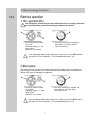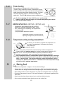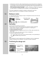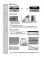
1
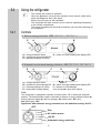
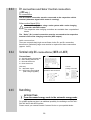
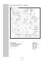
Operating Instructions
ABSORPTION - REFRIGERATOR for CARAVAN and MOTORHOME
RM 7601 L
RM 7605 L
RM 7651 L
RM 7655 L
RM 7801 L
RM 7805 L
RM 7851 L
RM 7855 L
EN
OPERATING INSTRUCTIONS / INSTALLATION INSTRUCTIONS
ABSORPTION REFRIGERATOR
Please state for future reference :
Type C40 / 110
Model number
.............................................
Product number
.............................................
Serial number
.............................................
T.B. MB 10/2005
English
Information
Environmental
Advice
Attention
Warning
Dansk
Deutsch
Ελληνικά
English
Español
Français
via INTERNET
www.dometic.com
Italiano
Customer Service
Nederlands
Norsk
Português
Suomi
Svensk
Safety instructions
Instructions for storing food in a refrigerator:
No refrigerator of any kind can improve the quality of the food; refrigerators can only maintain the food's quality for a short
duration as from the time of storing it.
Please observe the following particular conditions for storing food in a refrigerator that is built into a vehicle:
- A change in the climatic conditions such as temperature fluctuations
- High temperatures inside the vehicle when it is closed and parked in direct sunlight (temperatures are possible
up to 50°C)
- Use of the refrigerator whilst travelling with the power supply of 12V--DC
- A refrigerator built in behind a window and exposed to direct sunlight
- Storing the goods too soon, i.e. shortly after switching the device on for use
Under these particular conditions the refrigerator cannot guarantee having the temperature needed for food that perishes quikkly.
Foods that perish quickly include: all the products with a stipulated use-by date and a minimum storage temperature of +4°C
or less, especially for meat, poultry, fish, sausage, pre-packed foods.
Instructions
- Pack raw and cooked foods separately (e.g. in containers, aluminium foil, etc.)
- Only remove the outside packaging of single packs if all the necessary data, such as the use-by date, for
example, can also be read on the single packs.
- Do not leave cooled goods outside the refrigerator for too long.
- Place the foods with the next use-by date at the front, accordingly.
- Pack away any left-over food again and eat at the first opportunity.
- Wash your hands before and after touching any food.
- Clean the inside of the refrigerator at regular intervals.
Information :
Please observe the instructions and information regarding the use-by date on the outside packaging of the food.
Please observe the following sections in these instructions: "5.1 Cleaning" and "5.3 Storing food".
These operating instructions should be kept in a safe place.
If this device is passed on, please include these operating instructions with it.
© Dometic GmbH - 2004 - Subject to change without notice - Printed in Germany
2
TABLE OF CONTENTS
1.0
INTRODUCTION . . . . . . . . . . . . . . . . . . . . . . . . . . . . . . . . . . . . . . .
4
2.0
FOR YOUR SAFETY . . . . . . . . . . . . . . . . . . . . . . . . . . . . . . . . . . . .
4
2.1
2.2
Warning and safety notices . . . . . . . . . . . . . . . . . . . . . . . . . . . . . . . . . . . . . . . . . . . . . . . . . . . .
Coolant . . . . . . . . . . . . . . . . . . . . . . . . . . . . . . . . . . . . . . . . . . . . . . . . . . . . . . . . . . . . . . . . . . . .
4
4
3.0
WARRANTY AND CUSTOMER SERVICE . . . . . . . . . . . . . . . . . . .
5
3.1
Damages in transit . . . . . . . . . . . . . . . . . . . . . . . . . . . . . . . . . . . . . . . . . . . . . . . . . . . . . . . . . . .
5
4.0
DESCRIPTION OF MODEL . . . . . . . . . . . . . . . . . . . . . . . . . . . . . .
5
5.0
REFRIGERATOR GUIDE . . . . . . . . . . . . . . . . . . . . . . . . . . . . . . . .
5
Cleaning . . . . . . . . . . . . . . . . . . . . . . . . . . . . . . . . . . . . . . . . . . . . . . . . . . . . . . . . . . . . . . . . . . .
Using the refrigerator . . . . . . . . . . . . . . . . . . . . . . . . . . . . . . . . . . . . . . . . . . . . . . . . . . . . . . . . .
Storing food . . . . . . . . . . . . . . . . . . . . . . . . . . . . . . . . . . . . . . . . . . . . . . . . . . . . . . . . . . . . . . . .
Making ice cubes . . . . . . . . . . . . . . . . . . . . . . . . . . . . . . . . . . . . . . . . . . . . . . . . . . . . . . . . . . . .
Defrosting . . . . . . . . . . . . . . . . . . . . . . . . . . . . . . . . . . . . . . . . . . . . . . . . . . . . . . . . . . . . . . . . . .
Positioning the storage racks . . . . . . . . . . . . . . . . . . . . . . . . . . . . . . . . . . . . . . . . . . . . . . . . . . .
Door locking . . . . . . . . . . . . . . . . . . . . . . . . . . . . . . . . . . . . . . . . . . . . . . . . . . . . . . . . . . . . . . . .
Switching off the refrigerator . . . . . . . . . . . . . . . . . . . . . . . . . . . . . . . . . . . . . . . . . . . . . . . . . . .
Winter operation . . . . . . . . . . . . . . . . . . . . . . . . . . . . . . . . . . . . . . . . . . . . . . . . . . . . . . . . . . . . .
Interior light . . . . . . . . . . . . . . . . . . . . . . . . . . . . . . . . . . . . . . . . . . . . . . . . . . . . . . . . . . . . . . . . .
Changing the decor panel . . . . . . . . . . . . . . . . . . . . . . . . . . . . . . . . . . . . . . . . . . . . . . . . . . . . .
Changing the door . . . . . . . . . . . . . . . . . . . . . . . . . . . . . . . . . . . . . . . . . . . . . . . . . . . . . . . . . . .
Troubleshooting . . . . . . . . . . . . . . . . . . . . . . . . . . . . . . . . . . . . . . . . . . . . . . . . . . . . . . . . . . . . .
Maintenance . . . . . . . . . . . . . . . . . . . . . . . . . . . . . . . . . . . . . . . . . . . . . . . . . . . . . . . . . . . . . . . .
Product liability . . . . . . . . . . . . . . . . . . . . . . . . . . . . . . . . . . . . . . . . . . . . . . . . . . . . . . . . . . . . . .
Environmental hints . . . . . . . . . . . . . . . . . . . . . . . . . . . . . . . . . . . . . . . . . . . . . . . . . . . . . . . . . .
Disposal . . . . . . . . . . . . . . . . . . . . . . . . . . . . . . . . . . . . . . . . . . . . . . . . . . . . . . . . . . . . . . . . . . .
Energy-saving tips . . . . . . . . . . . . . . . . . . . . . . . . . . . . . . . . . . . . . . . . . . . . . . . . . . . . . . . . . . .
Technical data . . . . . . . . . . . . . . . . . . . . . . . . . . . . . . . . . . . . . . . . . . . . . . . . . . . . . . . . . . . . . .
Declaration of conformity . . . . . . . . . . . . . . . . . . . . . . . . . . . . . . . . . . . . . . . . . . . . . . . . . . . . . .
5
6
10
11
11
11
12
12
12
13
13
14
15
16
16
16
16
16
17
17
5.1
5.2
5.3
5.4
5.5
5.6
5.7
5.8
5.9
5.10
5.11
5.12
5.13
5.14
5.15
5.16
5.17
5.18
5.19
5.20
6.0
6.1
6.2
6.3
6.4
6.5
6.6
6.7
6.8
6.9
INSTALLATION GUIDE . . . . . . . . . . . . . . . . . . . . . . . . . . . . . . . . . . 18
Installation . . . . . . . . . . . . . . . . . . . . . . . . . . . . . . . . . . . . . . . . . . . . . . . . . . . . . . . . . . . . . . . . .
Draught free installation . . . . . . . . . . . . . . . . . . . . . . . . . . . . . . . . . . . . . . . . . . . . . . . . . . . . . . .
Ventilation and air extraction . . . . . . . . . . . . . . . . . . . . . . . . . . . . . . . . . . . . . . . . . . . . . . . . . . .
Installation of the ventilation system . . . . . . . . . . . . . . . . . . . . . . . . . . . . . . . . . . . . . . . . . . . . .
Installation recess . . . . . . . . . . . . . . . . . . . . . . . . . . . . . . . . . . . . . . . . . . . . . . . . . . . . . . . . . . . .
Securing the refrigerator . . . . . . . . . . . . . . . . . . . . . . . . . . . . . . . . . . . . . . . . . . . . . . . . . . . . . .
Connections gas/electrical installation . . . . . . . . . . . . . . . . . . . . . . . . . . . . . . . . . . . . . . . . . . . .
Gas installation . . . . . . . . . . . . . . . . . . . . . . . . . . . . . . . . . . . . . . . . . . . . . . . . . . . . . . . . . . . . . .
Electrical installation . . . . . . . . . . . . . . . . . . . . . . . . . . . . . . . . . . . . . . . . . . . . . . . . . . . . . . . . . .
3
18
19
20
21
22
22
23
23
25
1.0
INTRODUCTION
You have made an excellent choice in selecting the Dometic Absorption Refrigerator.
We are sure that you will be fully satisfied with your new appliance in all respects.
The appliance, which works silently, meets high quality standards and guarantees
the efficient utilisation of resources and energy throughout its entire life cycle, during
manufacture, in use and when being disposed of.
Before you start to use the appliance, please read the installation and operating
instructions carefully.
The refrigerator is designed for installation in leisure vehicles such as caravans or
motorcaravans. The appliance has been certified for this application in accordance with
EU Gas Directive 90/396/EEC.
2.0
FOR YOUR SAFETY
2.1
Warning and safety notices
Warning Attention
Never use a naked flame to check the appliance for leaks.
Protect children!
When disposing of the refrigerator, remove all refrigerator doors and leave the
storage rack in the refrigerator. This will prevent accidental locking in or suffocation.
If you smell gas:
- close the locking tap of the gas supply and the valve on the cylinder.
- open the windows and leave the room.
- do not switch on anything electrical.
- extinguish naked flames.
Never open the cooling unit; it is under high pressure.
Work on the gas, flue system and electrical components must only be
carried out by qualified service personnel.
It is imperative that the operating pressure should correspond to the data given on
the model plate of the appliance.
Compare the operating pressure data given on the model plate with the data on the
pressure monitor of the liquid gas cylinder.
Gas operation of the appliance is not permitted while travelling on ferries.
Covers ensure electrical safety and must only be removed using a tool.
The appliance must not be exposed to rain.
The refrigerator is not suitable for the proper storage of medications.
2.2
Coolant
Ammonia is used as a coolant.
This is a natural compound also used in household cleaning agents (1 litre of
Salmiak cleaner contains up to 200g of ammonia - about twice as much as is used
in the refrigerator). Sodium chromate is used for corrosion protection (1.8% of the
solvent).
In the event of leakage (easily identifiable from the unpleasant odour):
Switch off the appliance.
Air the room thoroughly.
Inform the authorised Customer Service department.
4
3.0
WARRANTY AND CUSTOMER SERVICE
Warranty arrangements are in accordance with EC Directive 44/1999/CE and the
normal conditions applicable for the country concerned. For warranty or other
servicing, please contact our Dometic Service department. Any damage due to improper use is not covered by the warranty. The warranty does not cover any modifications to the appliance or the use of non-original Dometic parts;
the warranty does not apply if the installation and operating instructions are not
adhered to and no liability shall be entertained. Parts can be ordered throughout
Europe from our Dometic Service department. Your Service Centre contact numbers
numbers are found in the “European Service Network” booklet
When contacting Dometic Service, please state the model, product number and
serial number together with the MLC Code, if applicable. You will find this information
on the data plate inside the refrigerator.
3.1
Damage in transit
After removing the packaging, check whether the refrigerator has been damaged
during transportation.
Any damage sustained in transit must be reported to the transportation company
concerned no later than seven days after delivery of the goods.
4.0
DESCRIPTION OF MODEL
e.g.
RM 7651 L
“L” with interior light
Last digit 1 = manual energy selection
Last digit 5 = automatic and manual energy selection
Model range
Refrigerator Mobil /
Mobile Absorber Refrigerator
5.0
5.1
0 = flat door
5 = curved door
REFRIGERATOR GUIDE
Cleaning
Before switching the refrigerator on to use it, we recommend that you clean it inside
and out, and repeat this at regular intervals.
Use a soft cloth and lukewarm water with a mild detergent.
Then rinse the appliance with clean water and dry thoroughly.
Remove dust from the refrigerator unit at yearly intervals using a brush or soft cloth.
ATTENTION
To avoid deterioration of materials:
Do not use soap or hard, abrasive or soda-based cleaning agents.
Do not allow the door seal to come into contact with oil or grease.
5
5.2
Using the refrigerator
5.2.1
The cooling unit is silent in operation.
When the appliance is first put into operation, there may be a mild odour
which will disappear after a few hours.
Ensure the living area is well ventilated.
The refrigerator will take several hours to reach its operating temperature
in the cooling compartment
The freezer compartment should be cold about one hour after switching on
the refrigerator.
Controls
A. Manual energy selection MES ( RM 76x1 L, RM 78x1 L)
E
C
A
A = energy selection switch
B = gas/electric thermostat AC/DC
C = operating displays (3 LEDs)
B
E = switch for frame heating with display LED
B. Automatic and manual energy selection AES (RM 76x5 L, RM 78x5 L)
E
A
B
C
D
=
=
=
=
A
C
D
B
energy selection switch
F
gas/electric thermostat AC/DC E = switch for frame heating with display LED
operating displays (4 LEDs)
F = dimmer for LED-displays
temperature setting display
(only accessable when door opens)
Note:
The refrigerator is equipped to operate on mains power, DC or liquid gas (propane/
butane). The desired power option is selected by means of energy selector switch (A).
Energy selector switch (A) has four settings: AC mains power, DC (12V),
Gas (liquid gas), OFF.
Appliances with automatic energy selection have the additional setting “AUTO” .
OFF
Gas
AC mains power
12V DC
Automatic energy selection
6
A. Manual Energy Selection
5.2.2
Electrical operation
1. 12V - operation (DC)
The refrigerator should only be used while the motor is running, otherwise
the on-board-battery would be discharged within a few hours!
B
A
C
1. Set energy selector switch
(A) to 12V .
Operating display “C”, 12V
lights “green”.
Appliance is in function.
2. Use rotary switch (B) to regulate the
temperature in the main refrigerator compartment.
If the operating display fails to light up ( it lights up “red” at AES models )
the device is not in operation. (For troubleshooting see 5.13)
2. Mains power
This option should only be selected where the supply voltage of the connection for
power supply corresponds to the value specified on the data plate. Any difference in
values may result in damage the appliance.
A
B
C
1. Set energy selector switch
(A) to 230V .
Operating display “C”, 230V
lights “green”.
Appliance is in function.
2. Use rotary switch (B) to regulate the
temperature in the main refrigerator compartment.
If the operating display fails to light up ( it lights up “red” at AES models )
the device is not in operation. (For troubleshooting see 5.13)
7
5.2.3
Gas operation
The refrigerator should only be operated using liquid gas
(Propane, Butane). Do not use Autogas, town gas or natural gas.
If the refrigerator is operated during travel using gas, the precautions
stipulated by the legislation in the respective country must be taken (in
conformity with the European standard EN 732).
Due to physical reasons, ignition faults could occur starting from an
altitude above sea level of approx. 1000 m /3280 ft. (No malfunction!)
As a basic rule, operation using gas is prohibited in petrol stations.
1. Open the valve of the gas cylinder
2. Open the shut-off valve to the gas supply.
C
1. Set energy selector switch (A) to gas
A
2. Set rotary switch (B) to “MAX” postion.
The ignition process is activated automatically, accompanied by a ticking sound
approx. 30 sec. Upon successful ignition, the display LED (C) “Gas” lights yellow.
The refrigerator is in function. Use rotary switch (B) to regulate the temperature in the
main refrigerator compartment.
B. Automatic Energy Selection (RM 76x5 L, RM 78x5 L only)
5.2.4
“AUTO”-operation
RM7XX5 L - models are equipped with an “AUTO”-MATIC function.
1. Set energy selection switch (A) to position
“AUTO” .
The LED "AUTO" illuminates.
Manual operation is possible at any time.
Explanations:
Upon switching on, the electronics automatically select one of the three
possible energy types: 230V - 12V - liquid gas. The control electronics
automatically ensure that the refrigerator is supplied with the optimum
source of energy in each respective case.
Priority
1.) Solar (12V DC)
2.) 230V AC
3.) 12V DC
4.) Liquid gas
The selected energy is displayed by the corresponding LED (i.e. 230V).
8
230 V - operation
If sufficient supply voltage is available (more than 200V), this power source is
selected as the first option ( no solar-system installed).
12 V - operation
12V operation should only be selected while the vehicle motor is running or there
is sufficient voltage available from the solar system. This can be detected from
the D+ connection of the alternator to the electronics, or from the respective signal on the solar charge regulator.
Gas operation
Gas operation is selected in the following circumstances:
No supply voltage available.
The vehicle engine is not running.
Supply voltage less than 200V
REFUELLING STOP
In order to prevent unintended switching to gas operation during refuelling,
the electronic system starts gas operation of the refrigerator, after the
motor has been turned off for 15 mins. During this time the appliance is in
stand-by operation mode and only the "AUTO" LED lights up.
The use of naked flames is prohibited in petrol station environments.
If the refuelling stop lasts longer than 15 mins., the refrigerator should be
switched off at the main switch (A), or switched over to another energy
type.
Gas faults (MES and AES)
5.2.5
A
C
If gas faults occur the operating LED “C”
flashes yellow.
Remedies:
Set the energy selector switch (A) to position “OFF”.
1. Is there any gas in the gas bottle?
2. Is the gas bottle valve open?
3. Is the on-board shut-off valve open?
4. Set the main switch (A) to “on”
The ignition starts again.
If after about 30 seconds the operating display (C) starts flashing red
again, the gas fault has not been cleared (e.g. air in the gas pipe).
5. Briefly switch the refrigerator off and then on again using main switch (A).
To remove air from the gas pipes, repeat this procedure 3-4 times.
If these actions do not help, please call an authorised Dometic Service
Centre.
9
5.2.6
Frame heating
Both models are equipped with a frame heating
(12VDC/3,5W) around the freezer compartment. During
summer months with high temperatures and humidity the
metal frame may have water droplets forming. To evaporate these droplets switch on the frame heating with
switch (A). The LED (B) indicates that the heating is on.
B
A
The frame heating will draw 12V DC power continuously.
Observe LED (B) when the engine is shut off while parking the vehicle.
Shut off the frame heating.
5.2.7
Additional functions (RM 76x5 L, RM 78x5 L only)
Temperature setting display (D) with 4 LED to
indicate the selected temperature (MIN - MAX)
LED - dimmer (E) for adjusting the brightness of
the display-LED
(only accessible when door opens)
D
E
Underneath the fascia is a knurled knob for
adjusting the brightness (see item E above)
5.2.8
Temperature setting cooling compartment
As shown, you are able to regulate the temperature of
B the cooling compartment, if necessary, by turning
rotary knob (B) .
medium setting
The cooling unit’s performance is influenced by ambient temperatures.
Please select the medium setting for ambient temperatures between +15°C
TIP and +25°C. The unit operates within its optimum performance range.
Dometic refrigerators work according to the absorption principle.
Due to physical reasons, an absorption system responds slowly to changes
made on the thermostat controller, or a loss in cooling through opening the
door, or storing food. The devices fulfill the cooling performance requirements of the Climatic Class SN acc. to EN/ISO 7371 in the temperature range
of +10°C to 32°C ambient temperature.
5.3
Storing food
Switch the refrigerator on approx. 12 hours before filling it.
Always store pre-cooled foods in the refrigerator. Make sure that the food is well
cooled when it is bought and also when transporting it. Use insulated cooling bags.
When taking food out of the refrigerator only open the refrigerator door very briefly.
Foods must be packed - best of all in closed containers - and stored separately from
each other.
Allow foods that have been warmed up to cool down before storing.
Store quickly perishable foods directly next to the cooling fins.
10
Products that could emit volatile, flammable gases must not be stored in the refrigerator
The refrigerator must not be exposed to direct sunlight. Please bear in mind that the tem-
perature inside a closed vehicle increases sharply if exposed to sunlight and that this can
reduce the efficiency of the refrigerator.
The air inside the refrigerator unit MUST be able to circulate freely without any hindrance.
(see also Section 6.3 "Ventilation and air extraction" in the Operating Manual).
The freezer compartment is suitable for making ice cubes and for short-term
storage of frozen food. It is not suitable as a means of freezing foods.
5.4
Making ice cubes
Ice cubes are best frozen overnight. At night, the refrigerator has less work to do and
the unit has more reserves.
1. Fill the ice
cube tray with
drinking water.
2. Place the ice cube
tray in the freezer
compartment.
Only use drinking water!
5.5
Defrosting
As time goes by, frost builds up on the fins.
When the layer of frost is about 3mm thick, the refrigerator should be defrosted.
1. Switch off the refrigerator, as described in Section 5.8 - "Switching off".
2. Remove the ice cube tray and food.
3. Leave the refrigerator door open.
4. After defrosting (freezer compartment and fins free of frost), wipe the cabinet dry
with a cloth.
5. Use a cloth to mop up the water from the freezer compartment.
6. Switch the refrigerator back on again.
The layer of ice must never be removed forcibly, nor may defrosting be
accelerated using a heat source.
Note:
Water thawing in the main compartment of the refrigerator runs into an appropriate
container at the back of the refrigerator. From there, the water evaporates.
5.6
Positioning the storage rack
Dismantling:
1. Loosen the front
and back securing
brackets.
1.
2. Move the storage
rack to the left and
remove it.
To fit the storage rack, the reverse order applies.
11
2.
5.7
Door locking
open
close
RM 7601/05 and RM 7801/05
5.8
RM 7651/55 and RM 7851/55
Switching off
A
1. Set energy selector switch (A)
to position "0" (OFF). The
appliance is now fully switched
off.
2. Secure the door open by means of the door
stop. The door will be slightly ajar. This is to
prevent mould from forming inside
the appliance.
Switching off gas operation
If the refrigerator is to be taken out of service for an extended period of
time, the on-board shut-off valve and the cylinder valve must be closed.
5.9
Winter operation
1. Check that the ventilation grills have not been
blocked by snow, leaves or similar.
2. When the ambient temperature falls below
+8°C, the optional winter covers should be
fitted. This protects the unit from excessively cold air.
roof exhaust ( R500 )
3. Affix the cover
and fasten it.
ventilation grille ( L500 )
ventilation grille ( L205 )
You should also attach the winter cover if the vehicle is taken out of service
for a longer period or while it is being cleaned from the outside.
12
5.10
Interior light
Changing the light bulbs
1.
2.
1. Remove cover.
90°
2. Detach defective light
bulb.
3. Fit new light bulb
Note:
For 12V DC :
1 light bulb 12V, 2W
4. Clip the cover back in
place.
5.11
Please contact Dometic Service Centres for
replacement light bulbs.
Changing the decor panel
1. Upper door
- remove the two screws holding the control panel
- unsrcew upper hinge pin (A) and remove the door
- unscrew upper part of the door frame and the panel
- insert new panel and fasten upper part of the door
frame
Please note: Carry out following steps BEFORE mounting the upper door.
A
B
2. Lower door
- unscrew both screws of the middle hinge pin (B)
- Pull out door and hinge in an upwards direction
- unsrcrew lower part of the door frame and remove the
decor panel
- insert new panel and fasten lower part of the door
frame
- insert lower door and fasten the middle hinge
- insert upper door and fasten the upper hinge pin (A)
- replace the control panel
Dimensions of the panels in mm:
Model
RM 7601/ RM 7605 (flat door)
RM 7801 / RM 7805
Height
857,0+/-1
252,5+/-1
Width
491,5+0/-1
491,5+0/-1
RM 7651/ RM 7655 (curved door)
RM 7851 / RM 7855
868,0+/-1
263,0+/-1
500,0+0/-1
500,0+0/-1
13
Thickness
3,2 max
3,2 max
2,5 max
2,5 max
5.12
Changing the doorhang
It is not always possible to change the door when the refrigerator is installed.
A
1. Remove rotary knobs and unscrew control
panel.
Open the freezer door, unscrew the hinge (A)
screw and keep it to hand.
2. Take off the door by moving it upwards.
3. Unscrew middle
hinge and remove
lower door.
4. Remove the middle
hinge.
5. Place hinge pin on the
opposite side.
5.
6. Positon the hinge at the
opposite side of the door
and insert lower door.
7. Affix the middle
hinge.
8. Insert freezer compartment door and fasten the upper hinge pin.
9. Replace the control panel and the rotary knobs.
14
5.13
Troubleshooting
Before calling the authorised Service Department, please check whether:
1. The instructions in the section "Using the refrigerator" have been followed.
2. The refrigerator is not tilted excessiveley.
3. It is possible to operate the refrigerator with an available power source.
Failure : The refrigerator does not work in gas operation mode.
Possible cause
Action you can take
a.) Gas bottle empty.
a.) Change gas bottle.
b.) Is the supply cut-out device open?
b.) Open the cut-out device.
c.) Air in the gas pipe?
c.) Switch device off and on again 3-4 times to
remove air from the gas pipe.
Failure : The refrigerator does not work on 12V.
Possible cause
Action you can take
a.) On-board fuse defective.
a.) Fit new fuse.
b.) On-board battery discharged.
b.) Check battery, charge it
c.) Engine not running.
c.) Start engine.
Failure : The refrigerator does not work on 230V.
Possible cause
Action you can take
a.) On-board fuse defective.
a.) Fit new fuse.
b.) No connection to supply voltage.
b.) Establish power connection.
c.) AES: gas operation despite connection
to the supply voltage?
c.) Appliance switches to gas operation due to
insufficient supply voltage (automatically
switches back to 230 V operation)
Failure : The refrigerator does not cool sufficiently.
Possible cause
Action you can take
a.) Inadequate ventilation to the unit.
a.) Check that the ventilation grilles are not
covered.
b.) The thermostat setting is too low.
b.) Turn the thermostat to a higher setting.
c.) There is too much ice on the condenser.
c.) Check that the refrigerator door seals
when shut.
d.) Too much warm food put inside.
d.) Let food cool down first.
e.) Appliance running for a short time.
e.) Wait several hours, check again.
15
5.14
Maintenance
Works on gas components and electical installation may only be carried out
by authorised personnel. We recommend to contact your Dometic Service
Centre.
EN 1949 stipulates that the appliance´s gas equipment and it’s associated fume
system must be inspected after installation and a certificate issued.
Afterwards a qualified technician must inspect according to EN 1949 every two
years and a certificate issued.
It is the user’s responsibily to arrange for inspections after purchase.
It is recommended that the gas burner be inspected and cleaned as necessary at
least once a year.
We recommend maintenance following an extended shutdown of the vehicle.
5.15
Product liability
Product liability of Dometic GmbH does not include damages which may arise from
faulty operation, improper alterations or intervention in the equipment, adverse effects
from the environment such as changes in temperature and air humidity, which may
impact the equipment itself or the direct vicinity of the equipment or persons in the
area.
5.16
Environmental hints
Refrigerators manufactured by Dometic GmbH are free of CFC/HCFC and HFC.
Ammonia (a natural compound of hydrogen and nitrogen) is used in the cooling unit
as a coolant. The non-ozone-hazardous cyclopentan is used as a propellant in the
manufacture of the PU foam insulation.
5.17
Disposal
In order to ensure that the recyclable packaging materials are re-used, these should
be sent to the usual local collection system.
The appliance should be transferred to a suitable waste disposal company that will
ensure re-use of the recyclable components and proper disposal of the rest.
For eco-friendly draining of the coolant from all absorber refrigeration units, a suitable
disposal plant should be used.
5.18
Energy-saving tips
At an average ambient temperature of approx. 25°C, it is sufficient to operate the
refrigerator at the middle thermostat setting (for both gas and mains voltage).
Where possible, always store goods that have previously been cooled.
Do not position the refrigerator in direct sunlight.
Constant circulation of air must be supplied to the refrigerator unit.
Defrost regularly.
Open the door only for a short time when removing goods from the refrigerator.
Run the refrigerator for about 12 hours before filling it.
16
5.19
Technical data
Model
Dimensions
H x W x D (mm)
depth incl. door
Groos capacity Usable
Connection
incl. freezer
capacity of
Mains / Battery
compartment freezer
compartment
* Consumption
electricity / gas
in 24 hrs
Netweight
Ignition
Flame
Failure
Device
RM 7601(L)
RM 7605(L)
RM 7801(L)
RM 7805(L)
1245x525x543
1245x525x543
1245x525x599
1245x525x599
142 lit.
142 lit.
167 lit.
167 lit.
25,lit.
25 lit.
30 lit.
30 lit.
190 W / 170 W
190 W / 170 W
190W / 170 W
190W / 170 W
ca.3,2 KWh / 380 g
ca.3,2 KWh / 380 g
ca.3,2 KWh / 380 g
ca.3,2 KWh / 380 g
42 kg
42 kg
44,0 kg
44,0 kg
X
X
X
X
standard door
standard door
standard door
standard door
RM 7651(L)
RM 7655(L)
RM 7851(L)
RM 7855(L)
1245x525x570
1245x525x570
1245x525x626
1245x525x626
150 lit.
150 lit.
175 lit.
175 lit.
26 lit.
26 lit.
31 lit.
31 lit.
190 W / 170 W
190 W / 170 W
190W / 170 W
190W / 170 W
ca.3,2 KWh / 380 g
ca.3,2 KWh / 380 g
ca.3,2 KWh / 380 g
ca.3,2 KWh / 380 g
43 kg
43 kg
44,7 kg
44,7 kg
X
X
X
X
curved door
curved door
curved door
curved door
We reserve the right to make technical changes.
*Average consumption measured at an average ambient temperature of 25°C in pursuance of
ISO Standard.
5.20
Declaration of conformity
17
6.0
INSTALLATION GUIDE
On installation of the appliance, the technical and administrative regulations of the
country in which the vehicle will first be used must be adhered to. Otherwise the
refrigerator must be installed as described in these instructions. In some OEM applications it may not be possible for these instructions to be followed exactly. In this case
an authorised Dometic representative may issue supplementary instruction
In Europe, for example, gas appliances, cable laying, installation of gas
cylinders, as well as approval and checking for leaks must comply with
EN 1949 for liquid gas units in vehicles.
6.1
Installation
The appliance and its fume extraction shall be installed in such a way as to be accessible for servicing at all times and must be capable of easy removal and installation.
The appliance may only be installed by authorised personnel.
Installation and connection of the appliance must comply with the latest
technical regulations, as follows:
The electrical installation must comply with national regulations.
Technical regulations EN 60335-1, EN 60335-2-24, EN 1648-1 , EN 1648-2
The gas installation must comply with national regulations.
Technical regulations EN 1949
Technical regulations EN 732
Local and building control department requirements
The appliance shall be installed in such a way that it is shielded from
excessive heat radiation.
Excessive heat impairs performance and raises the energy consumption of the
refrigerator.
Any installation that is not carried out by qualified persons will jeopardize the manufacturer's guarantee.
6.1.1
Side installation
If the appliance is installed on the same side of the vehicle as the entrance
door, it is desirable that the door does not cover the refrigerator’s vents. If this cannot
be avoided there must be a gap of at least 25mm between the door and the vents.
6.1.2
Rear installation
If the refrigerator is mounted at the rear of the vehicle you must ensure the lower grille
is not covered by the bumper or rear lights. This would be prevent the air from circulating properly and cause problems in warm weather.
Air vent grille not
blocked: OK!
An installation that is not carried out by qualified persons causes a
reduction in the cooling capacity and will jeopardize the manufacturer's guarantee.
18
6.2
Draught-free installation
The refrigerator must be sealed in accordance with EN 1949.
Do NOT use any easily inflammable materials (in particular silicone sealing
agent or similar) for sealing! The device manufacturer's product liability
and guarantee shall lapse if such materials are used.
Illustrated below is a typical approved method of sealing.
Proposal :
FIG. 1
B
A
Using the Installation Sealing Kit from Dometic
(available from Dometic)
Insert lipped seals (A) into the installation recesses at
the bottom and at each side (FIG 1, 2, 3).
Insert deflector plate (B), fitted with a lipped seal (A) of
heavy-duty, non- flammable material, into the
installation recess (see Fig. 4).
Insert deflector plate (B) in such a way that the hot air
escapes through the air vent grille into the open air.
Affix the discharge plate to the caravan wall, not to
the refrigerator !
In addition, discharge plate (B) with its lipped seal (A)
must seal the refrigerator off from the living area (see
FIG. 1,4).
Ensure that the refrigerator is installed level in the
recess.
B
A
FIG. 2
A
FIG. 3
FIG. 4
Finally, push the refrigerator into the recess from the front.
This installation option facilitates the removal and installation of the appliance
for servicing.
Comment:
Other methods of sealing may be approved. However the chosen method must prevent draughts entering the living space of the motorhome. Failure to seal correctly will
allow warm air to collect around the refrigerator and its performance will be affected.
If the cavity between the vehicle’s wall and the refrigerator is sealed so that fumes
cannot penetrate the living area it is possible to vent the flue gas directly through the
upper grille
Do not use any kind of aluminium flue pipe (e.g. T-piece) to lead the flue gas out.
Deviations shall require the consent of the manufacturer.
19
Ventilation and extraction
A correct installation is important for correct operation of the appliance to ensure,
there is no build-up of heat at the back of the appliance. This heat must be allowed
to escape into the open air.
In the event of high ambient temperatures, full performance of the cooling unit
can only be achieved by means of adequate ventilation and extraction.
Stopper
strip with
profiled
joint
L500
A
H
10-20mm
L500
Stopper
strip with
profiled
joint
Minimum height of ventilation
R500
Minimum height of ventilation
6.3
Stopper
strip with
profiled
joint
A
H
10-20mm
Stopper
strip with
profiled
joint
L500
Fig.1
Fig.2
Installation of lower ventilation
grille (L500) with roof exhaust (R500).
Installation of lower and upper ventilation grilles (L500).
Minimum height of ventilation ( mm) H
☺☺☺ B.
☺☺
A.
Roof exhaust R500
Upper ventilation L500
Lower ventilation L500 Lower ventilation L500
1250
1400
☺
C.
Upper ventilation L500
Lower ventilation L205
(no mosquito net)
1400
The unit is ventilated through openings in the wall or roof of the vehicle.
(Fig. 1 and Fig. 2). Fresh air enters at the bottom and the warmed air flows off
through the upper ventilation grille (flue effect). The side walls of the ventilation
shaft should be local to avoid the build up of condensation and drafts. The parts of
the shaft walls, which are situated above and next to the exhaust for the combustion gases, must be made of highly inflammable material. The upper ventilation grille should be positioned as high as possible above condenser (A) (observe minimum ventilation heights). The lower ventilation grille should be flush with the
floor of the vehicle, allowing any gas leakages (heavier than air) to escape directly
into the open air. Should this arrangement prove impossible, a ventilation aperture
must be introduced by the manufacturer of the vehicle into the recess floor intended
for the unit's installation, in order to avoid the accumulation, on this floor, of any
non-combusted gas which might escape (according to EN 1949). It is desirable to fit
the hole with wire mesh or similar, and an angle plate to protect it from stones, mud
etc., the wire mesh must not reduce the effective area of 13cm2 (EN1949). The
ventilation grilles must have a free cross section of at least 400cm2. Here it
should be noted that protective insect nets behind the ventilation grilles can reduce
the free cross section by up to 50%.
Correct mounting of the lower ventilation grille facilitates the access to
the electrical and gas connections during maintenance work.
20
6.4
Installing the ventilation system
L 500
To install the ventilation grilles, cut two rectangles (451mm x 341mm) in the
outer wall of the vehicle (for position of the cuts, see point 6.3).
1. Seal the mounting frame, making it waterproof.
2. Insert the frame and
screw into position.
4. Lock the ventilation grilles.
3. Insert the ventilation
grilles.
5. Insert winter cover
R 500
Measurements of roof exhaust R500
Length
Width
Height
595 mm
205 mm
150 mm
Roof cut out: 87mm X 507 mm
1. Seal the installation
bays and screw
them to the vehcile
roof
2 . Place the hood in
postion and screw
it to the installation
bays.
L 205
To install the ventilation grilles, cut a rectangle (451mm x 156mm) in the outer
wall of the vehicle (for position of the cuts, see point 6.3).
Item 1 does not apply for installation
framess with an integrated seal.
1. Seal the frame waterproof.
2. Screw on the frame.
21
3. Insert and lock the ventilation grilles.
6.5
Installation recess
The refrigerator must be installed draught-free in a recess (see “6.2”).
The measurements of the recess are given in the table below.
Push the appliance far enough into the recess until the front edge of the refrigerator
casing is flush with the front of the recess. Allow a gap of 10-20 mm between the back
wall of the recess and the refrigeration unit. The floor of the recess must be level, allowing the appliance to be pushed easily into its correct position. The floor must be substantial enough to bear the weight of the appliance (no hollow space underneath).
Ensure that the refrigerator is installed level in the recess.
Recess measurements:
Width of recess = W
Width of recess = W
Model
Hight H
Width W
Depth T
RM 7601 / RM 7605
1248 mm
530 mm
510 mm
RM 7651 / RM 7655
1248 mm
530 mm
510 mm
RM 7801 / RM 7805
H RM 7851 / RM 7855
1248 mm
530 mm
565 mm
1248 mm
530 mm
565 mm
Affix strip to side wall.
Seal i.e.V seal.
T
Stopper strips for example are affixed
in the installation bay, at the sides, at
the bottom and at the top and are fitted
with flexible sealant strips
6.6
plan view
Securing the refrigerator
In the sidewalls of the refrigerator, there are four plastic
sleeves with screws for securing the refrigerator. The
sidewalls or rails attached for securing the refrigerator
must be designed in such a way that the screws will
remain firmly in place even when under increased load
(while the vehicle is moving).
Always insert screws through the sleeves provided;
otherwise, structural parts embedded in the foam,
such as cables, etc., may be damaged.
Once the refrigerator is in its final position, secure the
screws into the wall of the recess.
The screws must penetrate
through the sheet metal
casing of the refrigerator.
22
6.7
Connections for gas / electrical installation
Terminal block
12VDC permanent connection
Terminal block
12VDC heating element
Gas valve
connection gas supply
Terminal block
12V DC conn. power module
and D+ input
6.8
Gas installation
The rules in point 6.1 must be adhered to.
When running on gas, these appliances are intended exclusively to use
liquid gas (propane/butane) - under no circumstances should town gas or
natural gas be used (EN 27418).
A fixed, pre-set pressure regulator complying with EN 12864 must be
connected to the liquid gas cylinder.
The pressure regulator must concur with the operating pressure specified
on the data plate of the appliance. The operating pressure corresponds to
the standard pressure of the country of specification (EN 1949, EN 732).
Only one connection pressure is permissible for any one vehicle. A plate
showing the permanent, clearly legible notice must be displayed in full view
at the point where the gas cylinder is installed.
The gas connection to the appliance must be installed securely and at
zero potential using tube connectors and must be securely connected to the
vehicle (a hose connection is not permissible) (EN 1949) .
23
Inflamable material should not be in immediate proximity to the burner.
The gas connection to the appliance is effected by means of a suitable
coupling tube fitting L8, DIN 2353-ST, complying with EN 1949 (e. g. Ermeto).
The gas connection may only be carried out by a qualified
personnel.
Following proper installation, a testing for leakage and a flame test must be carried out by *qualified personnel in compliance with EN 1949 .
A certificate of testing must be issued.
* qualified personnel
Qualified personnel are accredited experts who are able, by virtue of their training and knowledge,
to vouch for the correct implementation of the leakage test.
ATTENTION
15 Nm
max
20 Nm
max
SW 14
SW 17
C
The refrigerator must be equipped with a gas cock
(C) in the supply line to allow the supply to be disconnected.
Such a cut-out device must be readily accessible to the user.
Gas pressure
Category
mbar
I3P(30)
30
I
3P(37)
I3P(50)
37
50
I3+
28-37
30-37
I3B/P(50)
I3B/P(30)
50
30
•
•
•
•
•
BE
DK
DE
FI
•
FR
•
GR
•
IE
•
•
•
IS
•
IT
LU
NL
•
•
NO
•
AT
PT
•
•
SE
•
•
•
CH
ES
UK
•
•
•
•
•
24
•
•
•
6.9
Electrical installation
Electrical installation may only be carried out by qualified personnel.
The connection cables must be laid in such a way that they do not come
in contact with hot components of the unit/burner or with sharp edges.
The electrical installation must comply with national regulations
(EN 60335-2-24, EN 1648-1, EN 1648-2 for Europe).
It is advisable to run the incoming supply through an on-board fuse or
automatic circuit breaker. The power cable must be laid in such a way
that it does not come in contact with hot components of the unit/burner
or with sharp edges.
Changes at the internal electrical installation or the connection of other
electrical components (e.g. additional fan) to the internal wiring of the
appliance will expire the e1/ CE admittance as well as any claims from
guarantee and product liability!
6.9.1
Power line connection
The power must be supplied via a properly earthed socket outlet or hardwired connection.
Where a socket outlet is used for the mains connection lead, the outlet
must be freely accessible.
It is advisable to run the incoming supply through an on-board fuse or automatic
circuit breaker. The power cable must be laid in such a way that it does not come in
contact with hot components of the unit/burner or with sharp edges.
If the connection cable is damaged it must be replaced by the Customer
Service at Dometic, or by respectively qualified personnel, in order to
prevent any hazards.
6.9.2
Battery connection
The machine's mains 12V connection cable is connected (observing correct
polarity) to a terminal strip. The cabling must be direct and by the shortest possible
route to the battery and alternator respectively (motorcaravan).
Cross-sectional area of cable
Motorcaravan
Caravan (inside)
6 mm²
10 mm²
Caravan (outside)
min 2,5 mm²
Length of cable
<6m
2,5mm²
>6m
(EN1648-1)
The 12V circuit must be protected with a 20A fuse.
The heating element circuit must be connected to the vehicle battery by a suitable
ignition operated relay in order that the 12V supply is only live while the vehicle
ignition is switched on.
The connection C/D (interior light, electronics ; cable black / violet) must be
permanently attached, and must not be cut-out when the vehicle ignition key is
turned off. This can be realised with an on-board habitation battery .
For 12V operation any habitation isolation relay must be by-passed.
This 12V permanently connection must be protected with a 2A fuse!
If the appliance is installed in a caravan the respective leads for 12V+
and 12V- the connections A/B and C/D must not be connected to each
other on the caravan-side ( EN 1648-1).
25
6.9.3
D+ connection and Solar Control connection
( AES only )
D+ connection
The D+ control connection must be connected to the respective vehicle
terminal (alternator signal while motor is running).
Solar control input (S+):
Connection only when using a solar system with a solar charging
controller with AES output.
The respective solar charging controllers are available from a specialized
dealer.
The “Solar” (S+) control connection must be connected to the respective
terminal of the solar charging controller (AES output).
Cable cross-sections
There are no particularly high current flows via the D+ and S+ connection;
therefore no particularly large cross-section is required for these connections
(approx. 1mm²).
6.9.4
Terminal strip DC connections (MES and AES)
Connections:
A = Ground heating element DC
B = Plus heating element DC
C = Ground electronics
D = Plus electronics
(RM7605)
D+ = alternator signal
S+ = AES-input-control signal
(solar charge regulator)
C D
12V DC
heating-connection
permanent DC-connection
C
D
6.9.5
B
A
Retrofitting
RETROFITTING
From the manual energy mode to the automatic energy mode
For all MES appliances there is an additional possibility for retrofitting to an RM 76x5 /
RM 78x5 device with AES functions.
Please consult your nearest Dometic Customer Service or your specialist dealer.
26
6.9.6
Wiring diagram
Wiring diagram for RM 76x1 L / RM 78x1 L
permanently connection DC
C
D
ionisation
electrode
Burner
Control
Device
ignition
plug
ignition unit
Ground
gas burner
terminal block heating element DC
Gas
Valve
Switch
Frame
Heating
B
A
Reed contacts
(sensor switching)
heating element DC
temp. sensor
heating element AC
lighting DC
Power Module
Ground
mains
connection
Connections:
Colours:
A = Ground heating element DC
B = Plus heating element DC
C = Ground electronics
D = Plus electronics
schwarz = black
violett = violet
braun = brown
weiss = white
grün = green
gelb = yellow
rot = red
For operation, it is compulsory to provide the device with a permanent 12V
DC connection at terminals C/D (permanent voltage supply for the functional electronics).
27
Wiring diagram for RM 76x5 L / RM 78x5 L
permanently connection DC
C
D
ionisation
electrode
Burner
Control
Device
ignition
plug
ignition unit
Ground
gas burner
terminal block heating element DC
Gas
Valve
Switch
Frame
Heating
B
A
Reed contacts
(sensor switching)
heating element DC
temp. sensor
heating element AC
lighting DC
Power Module
Ground
mains
connection
Connections:
Colours:
A = Ground heating element DC
B = Plus heating element DC
C = Ground electronics
D = Plus electronics
schwarz = black
violett = violet
braun = brown
weiss = white
grün = green
gelb = yellow
rot = red
28
29
Dometic GmbH
In der Steinwiese 16
D-57074 Siegen
www.dometic.de/caravan
www.dometic.com