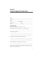
1
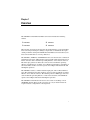
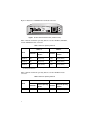
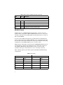
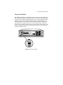
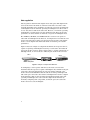
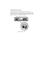
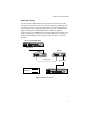
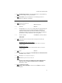
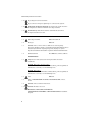
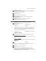
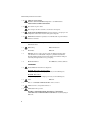
AT-MC13 AT-MC14 AT-MC15 AT-MC16 Ethernet Media Converters Installation Guide PN 613-10724-00 Rev C Copyright 2001 Allied Telesyn International Corp. 960 Stewart Drive Suite B, Sunnyvale CA 94086 USA All rights reserved. No part of this publication may be reproduced without prior written permission fro Allied Telesyn International Corp. e Ethernet is a registered trademark of Xerox Corporation. All other product names, company names, logos or other designations mentioned herein are trademarks or registered trademarks of their respective owners. Allied Telesyn International Corp. reserves the right to make changes in specifications and other information contained in this document without prior written notice. The information provided herein is subject to change without notice. In no event shall Allied Telesyn International Corp. be liable for any incidental, special, indirect, or consequential damages whatsoever, including but not limited to lost profits, arising out of or related to this manual or the information contained herein, even if Allied Telesyn International Corp. International Corp. has been advised of, known, or should have known, the possibility of such damages. Electrical Safety and Emission Compliance Statement Standards: This product meets the following standards. U.S. Federal Communications Commission DECLARATION OF CONFORMITY Manufacture Name: Allied Telesyn International Corp. Manufacture Address: 960 Stewart Drive, Suite B Sunnyvale, CA 94085 USA Manufacture Telephone: 408-730-0950 Declares that the product: Ethernet Media Converters Model Numbers: AT-MC13, AT-MC14, AT-MC15, AT-MC16 This product complies with FCC Part 15B, Class B Limits: This device complies with part 15 of the FCC Rules. Operation is subject to the following two conditions: (1) This device must not cause harmful interference, and (2) this device must accept any interference received, including interference that may cause undesired operation. RADIATED ENERGY Note: This equipment has been tested and found to comply with the limits for a Class B digital device pursuant to Part 15 of FCC Rules. These limits are designed to provide reasonable protection against harmful interference in a residential installation. This equipment generates, uses and can radiate radio frequency energy and, if not installed and used in accordance with instructions, may cause harmful interference to radio or television reception, which can be determined by turning the equipment off and on. The user is encouraged to try to correct the interference by one or more of the following measures: - Reorient or relocate the receiving antenna. - Increase the separation between the equipment and the receiver. - Connect the equipment into an outlet on a circuit different from that to which the receiver is connected. - Consult the dealer or an experienced radio/TV technician for help. Changes and modifications not expressly approved by the manufacturer or registrant of this equipment can void your authority to operate this equipment under Federal Communications Commission rules. Industry Canada This Class B digital apparatus meets all requirements of the Canadian Interference-Causing Equipment Regulations. Cet appareil numérique de la classe B respecte toutes les exigences du Règlement sur le matériel brouilleur du Canada. iii Warning: In a domestic environment this product may cause radio interference in which case the user may be required to take adequate measures. RFI Emission EN55022 Class B $ 1 Immunity EN55024 $ 2 Warning (AT-MC13, AT-MC14, AT-MC16): This product requires shielded cables to comply with emission and immunity standards. If it is used with unshielded cables, the user may be required to take measures to correct the interference problem at their own expense. $ 3 Electrical Safety TUV-EN60950, UL1950, CSA 950 $ 4 Laser EN60825 $ 5 Important: Appendix B contains translated safety statements for installing this equipment. When you see the $, go to Appendix B for the translated safety statement in your language. Wichtig: Anhang B enthält übersetzte Sicherheitshinweise für die Installation dieses Geräts. Wenn Sie $ sehen, schlagen Sie in Anhang B den übersetzten Sicherheitshinweis in Ihrer Sprache nach. Vigtigt: Tillæg B indeholder oversatte sikkerhedsadvarsler, der vedrører installation af dette udstyr. Når De ser symbolet $, skal De slå op i tillæg B og finde de oversatte sikkerhedsadvarsler i Deres eget sprog. Belangrijk: Appendix B bevat vertaalde veiligheidsopmerkingen voor het installeren van deze apparatuur. Wanneer u de $ ziet, raadpleeg Appendix B voor vertaalde veiligheidsinstructies in uw taal. Important: L'annexe B contient les instructions de sécurité relatives à l'installation de cet équipement. Lorsque vous voyez le symbole $, reportezvous à l'annexe B pour consulter la traduction de ces instructions dans votre langue. Tärkeää: Liite B sisältää tämän laitteen asentamiseen liittyvät käännetyt turvaohjeet. Kun näet $-symbolin, katso käännettyä turvaohjetta liitteestä B. Importante: l’Appendice B contiene avvisi di sicurezza tradotti per l’installazione di questa apparecchiatura. Il simbolo $, indica di consultare l’Appendice B per l’avviso di sicurezza nella propria lingua. Viktig: Tillegg B inneholder oversatt sikkerhetsinformasjon for installering av dette utstyret. Når du ser $, åpner du til Tillegg B for å finne den oversatte sikkerhetsinformasjonen på ønsket språk. Importante: O Anexo B contém advertências de segurança traduzidas para instalar este equipamento. Quando vir o símbolo $, leia a advertência de segurança traduzida no seu idioma no Anexo B. Importante: El Apéndice B contiene mensajes de seguridad traducidos para la instalación de este equipo. Cuando vea el símbolo $, vaya al Apéndice B para ver el mensaje de seguridad traducido a su idioma. Obs! Bilaga B innehåller översatta säkerhetsmeddelanden avseende installationen av denna utrustning. När du ser $, skall du gå till Bilaga B för att läsa det översatta säkerhetsmeddelandet på ditt språk. iv Table of Contents Electrical Safety and Emission Compliance Statement . . . . . . . . . . . . iii Welcome to Allied Telesyn . . . . . . . . . . . . . . . . . . . . . . . . . . . . . . . . . . . . . . vii Where to Find Web-based Guides . . . . . . . . . . . . . . . . . . . . . . . . . . . . . . . . . vii Document Conventions . . . . . . . . . . . . . . . . . . . . . . . . . . . . . . . . . . . . . . . . . . vii Contacting Allied Telesyn Technical Support . . . . . . . . . . . . . . . . . . . . . . . . viii Online Support . . . . . . . . . . . . . . . . . . . . . . . . . . . . . . . . . . . . . . . . . . . . viii Telephone and Fax Support . . . . . . . . . . . . . . . . . . . . . . . . . . . . . . . . . . viii Technical Support E-mail Addresses . . . . . . . . . . . . . . . . . . . . . . . . . . . . .ix Returning Products . . . . . . . . . . . . . . . . . . . . . . . . . . . . . . . . . . . . . . . . . . . . . . ix FTP Server . . . . . . . . . . . . . . . . . . . . . . . . . . . . . . . . . . . . . . . . . . . . . . . . . . . . . ix For Sales or Corporate Information . . . . . . . . . . . . . . . . . . . . . . . . . . . . . . . . . . x Tell Us What You Think . . . . . . . . . . . . . . . . . . . . . . . . . . . . . . . . . . . . . . . . . . . x Chapter 1 Overview . . . . . . . . . . . . . . . . . . . . . . . . . . . . . . . . . . . . . . . . . . . . . . . . . . . . . . 1 Key Features . . . . . . . . . . . . . . . . . . . . . . . . . . . . . . . . . . . . . . . . . . . . . . . . . . . . 3 Status LEDs. . . . . . . . . . . . . . . . . . . . . . . . . . . . . . . . . . . . . . . . . . . . . . . . . . . . . 3 MDI/MDI-X Switch . . . . . . . . . . . . . . . . . . . . . . . . . . . . . . . . . . . . . . . . . . . . . . . 4 Fiber Link Test Switch . . . . . . . . . . . . . . . . . . . . . . . . . . . . . . . . . . . . . . . . . . . . 5 Auto-negotiation . . . . . . . . . . . . . . . . . . . . . . . . . . . . . . . . . . . . . . . . . . . . . . . . . 6 MissingLink . . . . . . . . . . . . . . . . . . . . . . . . . . . . . . . . . . . . . . . . . . . . . . . . . . . . . 7 Terminator Switch (AT-MC15 Only) . . . . . . . . . . . . . . . . . . . . . . . . . . . . . . . . . 8 External AC/DC Power Adapter . . . . . . . . . . . . . . . . . . . . . . . . . . . . . . . . . 9 Network Topologies . . . . . . . . . . . . . . . . . . . . . . . . . . . . . . . . . . . . . . . . . . . . . . 10 Standalone Topology . . . . . . . . . . . . . . . . . . . . . . . . . . . . . . . . . . . . . . . . . 10 Back-to-Back Topology . . . . . . . . . . . . . . . . . . . . . . . . . . . . . . . . . . . . . . . 11 Chapter 2 Installing the Media Converter . . . . . . . . . . . . . . . . . . . . . . . . . . . . . . . . . Verifying Package Contents . . . . . . . . . . . . . . . . . . . . . . . . . . . . . . . . . . . . . . . Planning the Installation . . . . . . . . . . . . . . . . . . . . . . . . . . . . . . . . . . . . . . . . . Reviewing Safety Precautions . . . . . . . . . . . . . . . . . . . . . . . . . . . . . . . . . Installing the Media Converter . . . . . . . . . . . . . . . . . . . . . . . . . . . . . . . . . . . . Warranty Registration . . . . . . . . . . . . . . . . . . . . . . . . . . . . . . . . . . . . . . . . . . . 13 13 13 15 16 17 v Chapter 3 Troubleshooting . . . . . . . . . . . . . . . . . . . . . . . . . . . . . . . . . . . . . . . . . . . . . . . 19 Appendix A Technical Specifications . . . . . . . . . . . . . . . . . . . . . . . . . . . . . . . . . . . . . . . 23 Physical . . . . . . . . . . . . . . . . . . . . . . . . . . . . . . . . . . . . . . . . . . . . . . . . . . . . . . 23 Temperature . . . . . . . . . . . . . . . . . . . . . . . . . . . . . . . . . . . . . . . . . . . . . . . . . . 23 Electrical Rating . . . . . . . . . . . . . . . . . . . . . . . . . . . . . . . . . . . . . . . . . . . . . . . 23 Agency Certifications. . . . . . . . . . . . . . . . . . . . . . . . . . . . . . . . . . . . . . . . . . . . 24 Appendix B Translated Safety and Emission Information . . . . . . . . . . . . . . . . . . . . . 25 Appendix C Technical Support Fax Order Form . . . . . . . . . . . . . . . . . . . . . . . . . . . . . 39 Incident Summary . . . . . . . . . . . . . . . . . . . . . . . . . . . . . . . . . . . . . . . . . . . . . . 39 vi Welcome to Allied Telesyn This guide contains instructions on how to install the AT-MC1x Series Ethernet Media Converters. Where to Find Web-based Guides The Allied Telesyn web site at www.alliedtelesyn.com provides you with an easy way to access the most recent documentation and technical information for all of our products. For product guides, you can go directly to the following web page: www.alliedtelesyn.com/support/prd_libs.htm. Document Conventions This guide uses several conventions that you should become familiar with first before installing the product. Note A note provides additional information. Caution A caution indicates that performing or omitting a specific action may result in equipment damage or loss of data. Warning A warning indicates that performing or omitting a specific action may result in bodily injury. vii Welcome to Allied Telesyn Contacting Allied Telesyn Technical Support You can contact Allied Teleysn technical support online or by telephone, fax, or e-mail. Online Support You can request technical support online by filling out the Online Technical Support Form at www.alliedtelesyn.com/support/supportf.asp or by accessing the Technical Support Knowledge Base from Allied Telesyn’s North American web site. You can use the Knowledge Base to submit questions to our technical support staff and review answers to previously asked questions. Telephone and Fax Support For Technical Support via fax, please fill out the “Technical Support Fax Order” on page 35 and send it to the appropriate location listed below. Americas United States, Canada, Mexico, Central America, South America Tel: 1 (800) 428-4835, option 4 Fax: 1 (425) 481-3790 Germany Germany, Switzerland, Austria, Eastern Europe Tel: (+49) 30-435-900-126 Fax: (+49) 30-435-70-650 Asia Singapore, Taiwan, Thailand, Malaysia, Indonesia, Korea, Philippines, China, India, Hong Kong Tel: (+65) 3815-612 Fax: (+65) 3833-830 Italy Italy, Spain, Portugal, Greece, Turkey, Israel Tel: (+39) 02-41-30-41 Fax: (+39) 02-41-30-42-00 Australia Tel: 1 (800) 000-880 Fax: (+61) 2-9438-4966 Japan Tel: (+81) 3-3443-5640 Fax: (+81) 3-3443-2443 France France, Belgium, Luxembourg, The Netherlands, Middle East, Africa Tel: (+33) 0-1-60-92-15-25 Fax: (+33) 0-1-69-28-37-49 United Kingdom United Kingdom, Denmark, Norway, Sweden, Finland Tel: (+0044) 1235-442500 Fax: (+44) 1-235-442680 viii AT-MC1x Series Installation Guide Technical Support E-mail Addresses United States and Canada [email protected] Latin America, Mexico, Puerto Rico, Caribbean, and Virgin Islands [email protected] Europe [email protected] Returning Products Products for return or repair must first be assigned a Return Materials Authorization (RMA) number. A product sent to Allied Telesyn without a RMA number will be returned to the sender at the sender’s expense. To obtain an RMA number, contact Allied Telesyn’s Technical Support at one of the following locations: North America Toll-free: 1-800-428-4835, option 4 Fax: 1-425-481-3790 Europe, Africa, and the Middle East Tel: +44-1793-501401 Fax: +44-1793-431099 Latin America, the Caribbean, and Virgin Islands Tel: international code + 425-481-3852 Fax: international code + 425-481-3895 Puerto Rico Tel: 1-800-424-5012, ext 3852 or 1-800-424-4284, ext 3852 Mexico Toll-free: 800-424-5012, ext 3852 Fax: international code + 425-481-3895 Asia and Southeast Asia Tel: +65-381-5612 Fax: +65-383-3830 Australia Toll-free: 1-800-000-880 Fax: +61-2-9438-4966 New Zealand Toll-free: 0800-45-5782 FTP Server If you need management software for an Allied Telesyn managed device and you know the file name of the software, you can download the software by connecting directly to our FTP server at ftp.alliedtelesyn.com. At login, enter ‘anonymous’ as the user name and your e-mail address for the password. ix Welcome to Allied Telesyn For Sales or Corporate Information You can contact Allied Telesyn for sales or corporate information at one of the locations below: Allied Teleyn International Corp. 19800 North Creek Parkway, Suite 200 Bothell, WA 98011 Tel: 1 (425) 487-8880 Fax: 1 (425) 489-9191 Allied Telesyn International Corp. 960 Stewart Drive, Suite B Sunnyvale, CA 94085 Tel: 1 (800) 424-4284 (US and Canada) Fax: 1 (408) 736-0100 Tell Us What You Think If you have any comments or suggestions on how we might improve this or other Allied Telesyn documents, please fill out the Send Us Feedback Form at www.alliedtelesyn.com/contact/feedbackf.asp. x Chapter 1 Overview The AT-MC1x Series Ethernet Media Converters includes the following models: q AT-MC13 q AT-MC15 q AT-MC14 q AT-MC16 These media converters are designed to extend the distance of your network by interconnecting twisted pair cabling to single-mode or multimode fiber optic cabling or thinnet cabling. The AT-MC1x Series Media Converters allow you to interconnect LAN devices over large distances. The AT-MC13, AT-MC14, and AT-MC16 media converters feature a 10Base-T twisted pair port and a 10Base-F fiber optic port. The twisted pair port has an RJ-45 connector and a maximum operating distance of 100 meters (328 feet). The fiber optic port has an ST or SC connector and a maximum operating distance of 2 kilometers (1.2 miles) to 100 kilometers (62 miles), depending on the model. These media converters operate at 10 Mbps and feature half- and full-duplex operation. The AT-MC15 features a 10Base-T twisted pair port and a 10Base2 thinnet port. The twisted pair port has an RJ-45 connector and a maximum operating distance of 100 meters (328 feet). The thinnet port has a BNC-type connector and a maximum operating distance of 185 meters (606 feet). The AT-MC15 operates at 10 Mbps and features half-duplex operation. The AT-MC1x Series Media Converters can be used on a desktop or in an AT-MCR12 chassis. These media converters are easy to install and do not require software configuration or management. 1 Figure 1 illustrates an AT-MC1x Series Media Converter. FIBER LINK TEST TX RX 10Base-F 10Base-T REC PWR REC NML LNK MDI LNK MDI-X MC13 ETHERNET MEDIA CONVERTER Figure 1 AT-MC1x Series Media Converter (AT-MC13 model) Table 1 lists the maximum operating distances for the AT-MC13, AT-MC14, and the AT-MC16 media converters. Table 1 Maximum Operating Distances 10Base-F Model 10Base-T Connector Maximum Operating Distance1 Connector Maximum Operating Distance AT-MC13 ST 2 km (1.2 mi) RJ-45 100 m (328 ft) AT-MC14 SC 2 km (1.2 mi) RJ-45 100 m (328 ft) AT-MC16 ST 15 km (9.3 mi) RJ-45 100 m (328 ft) 1. Maximum operating distance may be less depending on the duplex mode of the end stations and the type of fiber optic cabling used with the port. Table 2 lists the maximum operating distances for the AT-MC15 media converter. Table 2 Maximum Operating Distances 10Base2 Model AT-MC15 2 10Base-T Connector Maximum Operating Distance Connector Maximum Operating Distance BNC 185 m (606 ft) RJ-45 100 m (328 ft) AT-MC1x Series Installation Guide Key Features The media converters have the following key features: q LEDs for unit and port status q Full- or half-duplex mode operation (except AT-MC15) q Half-duplex mode operation (AT-MC15 only) q MissingLink notifies end-nodes of link failures (fiber models only) q Link Test feature performs a link test on the media converter’s fiber port q MDI/MDI-X switch that eliminates the need for a crossover cable q Internal termination on the BNC port (AT-MC15 only) q External AC/DC power adapter q Standard, compact size for desktop use or in an AT-MCR12 rackmount chassis Status LEDs Table 3 lists the status LEDs for the AT-MC1x Series Media Converters. Table 3 Status LEDs for the Media Converters LED Color Description PWR Green Power is applied to the media converter. LNK Green A link has been established on the port. REC Green Data is being received. All Models AT-MC13, AT-MC14 and AT-MC16 only NML Green The MissingLink feature is enabled and the media converter is functioning in normal operating mode. OFF The MissingLink feature is disabled and the media converter is performing a link test. 3 Table 3 Status LEDs for the Media Converters (Continued) LED Color Description TX Green Data is being transmitted on the BNC port. RX Green Data is being received on the BNC port. ONLINE Green The BNC port is connected to an active 10Base2 segment. COL Green The BNC port is sensing a collision signal. AT-MC15 Only MDI/MDI-X Switch An RJ-45 port on a 10 Mbps Ethernet network device can have one of two possible wiring configurations: MDI or MDI-X. The RJ-45 port on a PC, router or bridge is typically wired as MDI, while the twisted pair port on a switch or hub is usually MDI-X. To connect two 10 Mbps network devices together that have dissimilar port wiring configurations, such as MDI to MDI-X, you use a straight-through cable. To connect two network devices that have an RJ-45 port with the same wiring configuration, such as MDI to MDI, you use a crossover cable. The RJ-45 port on the media converters feature an MDI/MDI-X button. You can use this button to configure the twisted pair port on the media converter as either MDI or MDI-X, thus eliminating the need for a crossover cable regardless of the type of network device you are connecting to the unit. Table 4 lists the pinouts of the RJ-45 ports for both MDI and MDI-X wiring configurations. Table 4 RJ-45 Pinout MDI Pinout MDI-X Pinout Pin Signal Pin Signal 1 TD + 1 RD+ 2 TD- 2 RD- 3 RD+ 3 TD+ 6 RD- 6 TD- 4, 5, 7, 8 N/A 4, 5, 7, 8 N/A 4 AT-MC1x Series Installation Guide Fiber Link Test Switch The AT-MC13, AT-MC14, and AT-MC16 media converters feature a Fiber Link Test switch. This switch sets the fiber port into an artificial link transmission state for testing without the twisted pair port being connected. When the Fiber Link Test switch is in the DOWN (default) position, the NML LED is green indicating that the media converter is functioning normally. For a link test, set the switch in the UP position. Be sure to set the switch back to the default position after performing a link test. If the switch is left in the UP position, the media converter will not function properly. Refer to Figure 2 for the location of the Fiber Link Test switch. FIBER LINK TEST TX RX 10Base-F 10Base-T REC PWR REC NML LNK MDI MDI-X LNK MC13 ETHERNET MEDIA CONVERTER FIBER LINK TEST Figure 2 Fiber Link Test Switch 5 Auto-negotiation Auto-negotiation determines the duplex mode of the ports. The duplex mode refers to the manner in which an end-node sends and receives data on the network. Depending on its capabilities, an end-node can operate in either halfor full-duplex mode. An end-node operating in half-duplex can either send or receive data, but not both at the same time. However, an end-node operating in full-duplex can send and receive data simultaneously. The best network performance is achieved when an end-node can operate in full-duplex mode. The AT-MC13, AT-MC14, and AT-MC16 media converters can operate in either full- or half-duplex mode. However, it is important to note that the endnodes connected to these media converters must operate in the same duplex mode to avoid a duplex mode mismatch which can result in poor network performance. Figure 1 shows an example of a duplex mode mismatch. A repeater (Unit 1), capable of operating in half-duplex mode only, is connected to the 10Base-F port on the media converter, while a switch (Unit 2), capable of either half- or full-duplex mode, is connected to the 10Base-T port on the media converter. Unit 1 Unit 2 FIBER LINK TEST TX RX 10Base-F 10Base-T REC PWR REC NML LNK MDI 100Base-TX Repeater MDI-X LNK Media Converter 100Base-TX Switch Figure 1 Example of a Duplex Mode Mismatch In attempting to auto-negotiate with Unit 1, the media converter will determine that the repeater is capable of half-duplex only and will set the port connected to the unit appropriately. In auto-negotiating with Unit 2, the media converter will determine that the switch can manage full-duplex and will set the port connected to the switch to full-duplex. The result is a duplex mode mismatch, with one unit operating in half-duplex and the other unit operating in full-duplex. You can resolve the duplex mode mismatch by manually configuring Unit 2, if possible, so that the port connected to the media converter is set to half-duplex. 6 AT-MC1x Series Installation Guide MissingLink The MissingLink feature enables the ports on the media converter to pass the “Link” status of their connections to each other. When the media converter detects a problem with one of the ports, such as the loss of connection to a endnode, the media converter shuts down the connection to the other port, thus notifying the end-node that the connection has been lost. For example, if the network twisted pair cable on an AT-MC14 were to fail, the module would respond by dropping the link on the fiber optic port. In this way, the AT-MC14 notifies the end-node connected to the fiber optic port that the connection on the twisted pair port has been lost. If the failure had started with the fiber optic cabling, the unit would drop the link to the twisted pair port. The value to this type of network monitoring and fault notification is that some hubs and switches can be configured to take a specific action in the event of the loss of connection on a port. In some cases, the unit can be configured to seek a redundant path to a disconnected end-node or send out a trap to a network management station, alerting the network administrator of the problem. Note MissingLink is disabled when you perform a link test with the Fiber Link Test switch. Consequently, to ensure that MissingLink is enabled on the media converter, always set the Fiber Link Test switch to the DOWN position during normal network operations. 7 Terminator Switch (AT-MC15 Only) The Terminator switch on the AT-MC15 media converter offers 50 Ω termination without the use of a T-connector and 50 Ω barrel terminator. Only end-point nodes need 50 Ω termination. Internal nodes on a thinnet segment should be connected to the cable through standard 10Base2 T-connectors. Refer to Figure 3 for the location of the Terminator switch. 10Base2 TERMINATOR O F F 10Base-T RX RX PWR ONLINE O N LNK COL TX MDI MDI-X TX MC15 ETHERNET MEDIA CONVERTER TERMINATOR O F F Figure 3 Terminator Switch 8 O N AT-MC1x Series Installation Guide External AC/DC Power Adapter An external AC/DC power adapter is included with the media converter for desktop operation (see Figure 4). The power adapter supplies 12 V DC to the media converter. Allied Telesyn supplies an approved safety compliant AC power adapter for the 120 and 240 V AC versions with an unregulated output of 12 V DC at 1 A. The power requirement for the AT-MC13, AT-MC14, and AT-MC16 media converters is 12 V DC, 500 mA. The power requirement for the AT-MC15 is 12 V DC, 300 mA Note The power adapter is not used if you install the media converter in an AT-MCR12 chassis. Figure 4 External AC/DC Power Adapter (North American Version) 9 Network Topologies The AT-MC1x Series Media Converters can be used in two different topologies: standalone and back-to-back. Both types of topologies are described below. Standalone Topology A standalone topology uses one media converter between the end-nodes. Figure 5 illustrates a standalone topology that uses an AT-MC13 media converter to connect two switches. 10Base-F Fiber Optic Switch 2 km (1.2 mi) AT-MC13 FIBER LINK TEST TX RX 10Base-F 10Base-T REC PWR REC NML LNK MDI MDI-X LNK MC13 ETHERNET MEDIA CONVERTER 100 m (328 ft) Fiber Optic 10BASE-T / 100BASE-TX FAST ETHERNET SWITCH A Twisted Pair 10BASE-T / 100BASE-TX PORT ACTIVITY 1X 3X 5X 7X 9X 11X 13X 15X 17X 19X 21X 23X 2X 4X 6X 8X 10X 12X 14X 16X 18X 20X 22X 24X 100M LINK / L /A ACTIVITY RS-232 TERMINAL PORT 10M LINK / HALF DUP/ FULL DUP D/C STATUS ACTIVITY COL 1 3 5 7 9 11 13 15 17 19 21 23 2 4 6 8 10 12 14 16 18 20 22 24 FAULT L /A D/C B RPS L /A PWR D/C RESET AT-8224XL Switch Figure 5 Standalone Topology 10 AT-MC1x Series Installation Guide Back-to-Back Topology In some network configurations you may want to interconnect two media converters in what is referred to as a back-to-back topology. In this topology, the media converters not only extend the distance of your network but also convert the fiber optic cable from twisted pair to fiber optic and back again. Figure 6 illustrates two AT-8224XL switches at different campuses interconnected by two AT-MC14 media converters. The 10Base-T ports on the media converters are connected to one 10/100Base-TX port on each switch, while the 10Base-F ports on the media converters are directly connected together. Campus 1: One AT-8224XL Switch 10BASE-T / 100BASE-TX FAST ETHERNET SWITCH A 10BASE-T / 100BASE-TX PORT ACTIVITY 1X 3X 5X 7X 9X 11X 13X 15X 17X 19X 21X 23X 2X 4X 6X 8X 10X 12X 14X 16X 18X 20X 22X 24X 100M LINK / L /A ACTIVITY RS-232 TERMINAL PORT 10M LINK / STATUS ACTIVITY HALF DUP/ FULL DUP D/C COL 1 3 5 7 9 11 13 15 17 19 21 23 2 4 6 8 10 12 14 16 18 20 22 24 FAULT L /A D/C B RPS L /A PWR D/C RESET 100 m (328 ft) AT-MC14 AT-MC14 FIBER LINK TEST TX RX 10Base-F 10Base-T REC REC LNK MDI MDI-X FIBER LINK TEST TX RX 10Base-T 10Base-F PWR REC NML LNK LNK MC14 ETHERNET MEDIA CONVERTER REC PWR NML MDI LNK MDI-X MC14 ETHERNET MEDIA CONVERTER 2 km (1.2 mi) 100 m (328 ft) Fiber Optic 10BASE-T / 100BASE-TX FAST ETHERNET SWITCH A Twisted Pair 10BASE-T / 100BASE-TX PORT ACTIVITY 1X 3X 5X 7X 9X 11X 13X 15X 17X 19X 21X 23X 2X 4X 6X 8X 10X 12X 14X 16X 18X 20X 22X 24X 100M LINK / L /A ACTIVITY RS-232 TERMINAL PORT 10M LINK / HALF DUP/ FULL DUP D/C STATUS ACTIVITY COL 1 3 5 7 9 11 13 15 17 19 21 23 2 4 6 8 10 12 14 16 18 20 22 24 FAULT L /A D/C B RPS L /A PWR D/C RESET Campus 2: One AT-8224XL Switch Figure 6 Back-to-Back Topology 11 Chapter 2 Installing the Media Converter This chapter explains how to install an AT-MC1x Series Media Converter on a desktop. To install the media converter in an AT-MCR12 chassis, refer to the AT-MCR12 Installation Guide. This guide can be downloaded from our web site at www.alliedtelesyn.com/support/prd_libs.htm. Verifying Package Contents Make sure the following items are included in your media converter package. If any item is missing or damaged, contact your sales representative for assistance. q One AT-MC1x Series Ethernet Media Converter q Four protective feet (for desktop use only) q External AC/DC power adapter (North America, Continental Europe, United Kingdom, or Australia) q This installation guide q Warranty card Planning the Installation Be sure to observe the following guidelines when planning the installation of your media converter. q The end-nodes connected to the media converter must operate at 10 Mbps. q The end-nodes connected to the ports of the AT-MC13, AT-MC14, and the AT-MC16 must be able to operate in the same duplex mode. These units can operate in either full- or half-duplex mode. q The end-nodes connected to the ports of the AT-MC15 must operate in half-duplex mode. 13 q Refer to Table 5 for the twisted pair cabling specifications. Table 5 Twisted Pair Port Specifications Model Cable Maximum Operating Distance All models Shielded or unshielded Category 3 or better 100 m (328 ft) q Refer to Table 6 for the thinnet cabling specifications. Table 6 Thinnet Port Specifications Model Cable Maximum Operating Distance AT-MC15 Shielded or unshielded Category 3 or better 185 m (606 ft) q Refer to Table 7 and Table 8 for the fiber optic cabling specifications. Table 7 Fiber Optic Port Specifications (Full-duplex) Model Connector Cable Maximum Operating Distance Maximum Allowable Loss Budget AT-MC13 ST 62.5/125 micron multimode 2 km (1.2 mi)1 20 dB at 850 nm AT-MC14 SC 62.5/125 micron multimode 2 km (1.2 mi)1 20 dB at 850 nm AT-MC16 ST 9/125 micron single-mode 15 km (9.3 mi) 13 dB at 1310 nm 1. Maximum operating distance over multimode fiber is 2 km (1.2 mi) if the maximum measured optical loss budget is less than 20 dB’s when measured at 850 nm optical wavelength. 14 AT-MC1x Series Installation Guide Table 8 Fiber Optic Port Specifications (Half-duplex) Number of Media Converters Connected Devices Maximum Operating Distance One Media Converter Inline Switch to Switch 372 m (1,221 ft) Workstation to Switch 372 m (1,221 ft) Switch to Class I Repeater 137 m (450 ft) Switch to Class II Repeater 185 m (607 ft) Switch to Switch 332 m (1,089 ft) Workstation to Switch 332 m (1,089 ft) Switch to Class I Repeater 97 m (318 ft) Switch to Class II Repeater 145 m (476 ft) Two Media Converters Inline Reviewing Safety Precautions Please review the following safety precautions before you begin to install the media converter. Caution Power to the hub must be sourced only from the adapter. $ 5 Warning (AT-MC13, AT-MC14) This is a “CLASS 1 LED PRODUCT” $ 7 (AT-MC16) Class 1 laser product. $ 8 Warning Do not stare into the laser beam. $ 9 Warning Lightning Danger: Do not work on equipment or cables during periods of lightening activity. $ 10 Caution Do not block air vents. $ 11 15 Caution Operating Temperature This product is designed for a maximum ambient temperature of 40 degrees C. $ 12 Caution All Countries: Install product in accordance with local and National Electrical Codes. $ 13 Installing the Media Converter To install an AT-MC1x Series Media Converter, perform the following procedure: 1. Remove all equipment from the package and store the packaging material in a safe place. Note Do not remove the dust cover from the fiber optic port until you are ready to connect the fiber optic cable. Dust contamination can adversely impact the operating performance of the port and the media converter. 2. If you are installing the media converter on a desktop, attach the four protective feet (provided) to each corner of the base of the unit. Do not attach the rubber feet if you are installing the unit in an AT-MCR12 chassis. 3. If you are installing the media converter in an AT-MCR12 chassis, refer to the chassis’ installation guide for instructions on how to install the unit, then proceed to Step 5. 4. Place the media converter on a level, secure surface (such as a desk or table), leaving ample space around the unit for ventilation. 5. For an AT-MC13, AT-MC14, or AT-MC16, remove the dust cover from the fiber optic connector and connect the cable to the fiber optic port. Verify that the near end-node transmitter port (TX) is connected to the far endnode receiver port (RX) and that the near end-node receiver port (RX) is connected to the far end-node transmitter port (TX). 6. For an AT-MC15, connect the thinnet cable to the 10Base2 port. 16 AT-MC1x Series Installation Guide 7. Connect the twisted pair cable to the 10Base-T port. 8. Set the MDI/MDI-X switch as follows: 9. — If you are connecting a workstation to the twisted pair port, set the MDI/MDI-X switch to the MDI-X position. (MDI-X is the default position.) — If you are connecting a hub or switch to the twisted port pair, set the MDI/MDI-X switch to the MDI position. Plug the AC/DC power adapter into an appropriate AC power outlet and insert the power plug into the DC receptacle located on the back of the unit. This step does not apply if you installed the unit in an AT-MCR12 chassis. 12 V D C Figure 7 12 V DC Connector on the Back of the Media Converter 10. Verify that the Power LED is green. If the LED is OFF, refer to “Troubleshooting” on page 19 for instructions. 11. Power ON the end-nodes. 12. Verify that the LNK LED for both the fiber optic port and the twisted pair port is green. The AT-MC15 has one LNK LED for the twisted pair port. If the LED is OFF, refer to “Troubleshooting” on page 19 for instructions. The media converter is now ready for use. Warranty Registration When you finish installing the product, register your product by completing the enclosed warranty card and sending it in. You can also fill out the registration online at www.alliedtelesyn.com/support/warrantyf.asp. 17 Chapter 3 Troubleshooting Follow the guidelines below to test and troubleshoot the installation in the event a problem occurs. If the PWR LED is OFF, do the following: q If the unit is installed on a desktop, check to be sure that the power adapter is securely connected to a power outlet and that the power adapter cable is securely connected to the back of the media converter. q If the unit is installed in an AT-MCR12 chassis, check that the unit is fully seated in the slot. q Verify that the power outlet has power by connecting another device to it. q Try using another power adapter. If the LNK LED for the twisted pair port is OFF, do the following: q Check that the end-node connected to the port is powered ON and is operating properly. q Check that the twisted pair cable is securely connected to the twisted pair port on the media converter and on the remote end-node. q Make sure that the twisted pair cable does not exceed 100 meters (328 feet) and that you are using Category 3 or better cable. q Verify that the end-node is operating at 10 Mbps and full- or half-duplex mode if connected to an AT-MC13, AT-MC14, or AT-MC16. q Verify that the end-node is operating at 10 Mbps and half-duplex mode if connected to an AT-MC15. 19 If the LNK LED for the fiber optic port is OFF, do the following: q Verify that the end-node connected to the port is ON and is operating properly. q Check that the fiber optic cable is securely connected to the fiber optic port on the media converter and on the remote end-node. q Check to be sure that the end-node connected to the port is operating at 10 Mbps. q Make sure that the fiber optic port on the remote end-node is operating in either full- or half-duplex mode. q Make sure that the cable connected to the fiber optic receiver port on the media converter is connected to the transmitter port on the remote end-node and that the fiber optic transmitter port on the media converter is connected to the receiver port on the end-node. q Test the attenuation on the fiber cable to ensure that it does not exceed acceptable values. q Verify that you are using the appropriate type of fiber optic cable and that you have not exceeded the maximum operating distance. For cable types and operating distances, refer to Table 7 on page 14 and Table 8 on page 15. q Check that the operating specifications (e.g., wavelength and maximum operating distance) of the fiber optic port on the end-node are compatible with the operating specifications of the fiber optic port on the media converter. See Table 7 on page 14 for fiber optic port specifications. 20 AT-MC1x Series Installation Guide If the LNK LED for the fiber optic port is ON, but there is a communication problem between the end-nodes connected to the media converter (and you are not running a Fiber Link Test), check the following: q Check that the end-nodes connected to the ports are operating at 10 Mbps. q Check that the end-nodes connected to the AT-MC13, AT-MC14, or AT-MC16 are operating in the same duplex mode. These units can operate in either full- or half-duplex mode. q Check that the Fiber Link Test switch on the media converter is in the DOWN position. q Check that the maximum allowable loss budget for the fiber optic cable has not been exceeded. Refer to Table 7 on page 14 for the fiber optic port specifications. If the NML LED on the AT-MC13, AT-MC14, or AT-MC16 is OFF, do the following: q Check that the end-nodes connected to the media converter are powered ON. q Check that the fiber optic cable is securely connected to the fiber optic port. q Verify that the appropriate fiber optic cable is being used. Refer to Table 7 on page 14 and Table 8 on page 15 for the fiber optic cable specifications. q Verify that the maximum allowable loss budget for the fiber optic cable has not been exceeded. If you are still experiencing problems after troubleshooting the installation, contact Allied Telesyn Technical Support for assistance. Refer to “Contacting Allied Telesyn Technical Support” on page viii or visit our web site at www.alliedtelesyn.com for support information. 21 Appendix A Technical Specifications Physical Dimensions (W x D x H): 10.5 cm x 9.5 cm x 2.5 cm (4.1 in x 3.7 in x 1.0 in) Weight: 294 g (10.4 oz) Temperature Maximum Operating: 0° C to 40° C (32° F to 104° F) Maximum Storage: -25° C to 70° C (-13° F to 158° F) Relative Humidity: 5% to 95% non-condensing Operating Altitude: Up to 3,048 meters (10,000 feet) Electrical Rating Input Supply Voltage: 12 V DC ± -5% Maximum Current: .5 Power Consumption: 6W AC Input Voltage: AT-MC13, AT-MC14, AT-MC16 500 mA AT-MC15 300 mA 23 Agency Certifications EMI/RFI: FCC Class A, IC Class A, EN 55022 Class B Safety: UL, CSA, TUV, IEC 825-1 CE Compliant Immunity: EN50082-1 1997 Immunity Standard 24 Appendix B Translated Safety and Emission Information Important: This appendix contains multiple-language translations for the safety statements in this guide. Wichtig: Dieser Anhang enthält Übersetzungen der in diesem Handbuch enthaltenen Sicherheitshinweise in mehreren Sprachen. Vigtigt: Dette tillæg indeholder oversættelser i flere sprog af sikkerhedsadvarslerne i denne håndbog. Belangrijk: Deze appendix bevat vertalingen in meerdere talen van de veiligheidsopmerkingen in deze gids. Important: Cette annexe contient la traduction en plusieurs langues des instructions de sécurité figurant dans ce guide. Tärkeää: Tämä liite sisältää tässä oppaassa esiintyvät turvaohjeet usealla kielellä. Importante: questa appendice contiene traduzioni in più lingue degli avvisi di sicurezza di questa guida. Viktig: Dette tillegget inneholder oversettelser til flere språk av sikkerhetsinformasjonen i denne veiledningen. Importante: Este anexo contém traduções em vários idiomas das advertências de segurança neste guia. Importante: Este apéndice contiene traducciones en múltiples idiomas de los mensajes de seguridad incluidos en esta guía. Obs! Denna bilaga innehåller flerspråkiga översättningar av säkerhetsmeddelandena i denna handledning. 25 Translated Safety and Emission Information Standards: This product meets the following standards. U.S. Federal Communications Commission DECLARATION OF CONFORMITY Manufacture Name: Allied Telesyn International Corp. Manufacture Address: 960 Stewart Drive, Suite B Sunnyvale, CA 94085 USA Manufacture Telephone: 408-730-0950 Declares that the product: Ethernet Media Converters Model Numbers: AT-MC13, AT-MC14, AT-MC15, AT-MC16 This product complies with FCC Part 15B, Class B Limits: This device complies with part 15 of the FCC Rules. Operation is subject to the following two conditions: (1) This device must not cause harmful interference, and (2) this device must accept any interference received, including interference that may cause undesired operation. RADIATED ENERGY Note: This equipment has been tested and found to comply with the limits for a Class B digital device pursuant to Part 15 of FCC Rules. These limits are designed to provide reasonable protection against harmful interference in a residential installation. This equipment generates, uses and can radiate radio frequency energy and, if not installed and used in accordance with instructions, may cause harmful interference to radio or television reception, which can be determined by turning the equipment off and on. The user is encouraged to try to correct the interference by one or more of the following measures: - Reorient or relocate the receiving antenna. - Increase the separation between the equipment and the receiver. - Connect the equipment into an outlet on a circuit different from that to which the receiver is connected. - Consult the dealer or an experienced radio/TV technician for help. Changes and modifications not expressly approved by the manufacturer or registrant of this equipment can void your authority to operate this equipment under Federal Communications Commission rules. Industry Canada This Class B digital apparatus meets all requirements of the Canadian Interference-Causing Equipment Regulations. Cet appareil numérique de la classe B respecte toutes les exigences du Règlement sur le matériel brouilleur du Canada. 26 AT-MC1x Series Installation Guide Warning: In a domestic environment this product may cause radio interference in which case the user may be required to take adequate measures. $1 RFI Emission EN55022 Class B $2 Immunity EN55024 $3 Warning (AT-MC13, AT-MC14, AT-MC16): This product requires shielded cables to comply with emission and immunity standards. If it is used with unshielded cables, the user may be required to take measures to correct the interference problem at their own expense. $4 Electrical Safety TUV-EN60950, UL1950, CSA 950 SAFETY $5 Power to the hub must be sourced only from the adapter. EUROPE—EC (AT-MC13, AT-MC14, AT-MC16) Use TÜV licensed AC adapter of 12 V DC, min 500 mA. EUROPE—EC (AT-MC15) Use TÜV licensed AC adapter of 12 V DC, min 300 mA. OTHER COUNTRIES (AT-MC13, AT-MC14, AT-MC16) Use a Safety Agency Approved AC adapter of 12 V DC, min 500 mA. OTHER COUNTRIES (AT-MC15) Use a Safety Agency Approved AC adapter of 12 V DC, min 300 mA. $6 Laser $7 This is a “CLASS 1 LED PRODUCT” (AT-MC13, AT-MC14) $8 Warning (AT-MC16): Class 1 Laser product. $9 Warning: Do not stare into the Laser beam. EN60825 At time of installation the Fiber Optic Lasers comply with FDA Radiation Performance Standard 21CFR Subchapter J, applicable at date of manufacture. Caution: Power cord is used as a disconnection device. To de-energise equipment disconnect the power cord. $ 10 LIGHTNING DANGER Danger: Do not work on equipment or cables during periods of lightning activity. $ 11 Do not block air vents. 27 Translated Safety and Emission Information Do not connect a telephone line into the signal connector. $ 12 Operating Temperature: This product is designed for a maximum ambient temperature of 40 degrees C. $ 13 All Countries: Install product in accordance with local and National Electrical Codes. Normen: Dieses Produkt erfüllt die Anforderungen der nachfolgenden Normen. $1 Hochfrequenzstörung EN55022 Klasse B $2 Störsicherheit EN55024 $3 Achtung (AT-MC13, AT-MC14, AT-MC16): Für dieses Produkt sind abgeschirmte Kabel erforderlich, damit den Richtlinien für Emission und Interferenzschutz entsprochen wird. Falls das Produkt mit nicht abgeschirmten Kabeln verwendet wird, können weitergehende Maßnahmen für die Korrektur von Interferenzproblemen auf Kosten des Benutzers notwendig werden. $4 Elektrische Sicherheit TUV-EN60950, UL1950, CSA 950 SICHERHEIT $5 Der Buchse darf nur aus dem Adpater Strom zugeführt werden. EUROPE—EC (AT-MC13, AT-MC14, AT-MC16) Gebrauchen Sie einen von TÜV zugelassenen Wechselstromadapter für Gleichstrom 12 Vdc, 500 mA. EUROPE—EC (AT-MC15) Gebrauchen Sie einen von TÜV zugelassenen Wechselstromadapter für Gleichstrom 12 Vdc, 300 mA. $6 Laser $7 Das ist ein “LED Produkt der Klasse 1” (AT-MC13, AT-MC14) $8 Warnung (AT-MC16): Laserprodukt der Klasse 1. $9 Warnung: Nicht direkt in den Strahl blicken. EN60825 Vorsicht: Das netzkabel dient zum trennen der stromversorgung. Zur trennung vom netz, kabel aus der steckdose ziehen. $ 10 GEFAHR DURCH BLITZSCHLAG Gefahr: Keine Arbeiten am Gerät oder an den Kabeln während eines Gewitters ausführen. $ 11 Entlüftungsöffnungen nicht versperren. 28 AT-MC1x Series Installation Guide Verbinden Sie nicht das Telefonkabel mit dem Signalverbindungsstecker. $ 12 Betriebstemperatur: Dieses Produkt wurde für den Betrieb in einer Umgebungstemperatur von nicht mehr als 40° C entworfen. $ 13 Alle Länder: Installation muß örtlichen und nationalen elektrischen Vorschriften entsprechen. Standarder: Dette produkt tilfredsstiller de følgende standarder. $1 Radiofrekvens forstyrrelsesemission EN55022 Klasse B $2 Immunitet $3 Advarsel (AT-MC13, AT-MC14, AT-MC16): Dette produkt skal bruges med afskærmede kabler for at overholde bestemmelserne vedrørende udstråling og støjimmunitet. Hvis det bruges med uafskærmede kabler, kan det blive påkrævet af brugeren at korrigere interferensproblemer for egen regning. $4 Elektrisk sikkerhed EN55024 TUV-EN60950, UL1950, CSA 950 SIKKERHED $5 Strømforsyningen til apparatet må udelukkende tages fra tilpasningstransformatoren. EUROPE - EC (AT-MC13, AT-MC14, AT-MC16) Brug kun TÜV godkendt vekselstrømstransformator på 12 Vdc, 500 mA. EUROPE - EC (AT-MC15) Brug kun TÜV godkendt vekselstrømstransformator på 12 Vdc, 300 mA. $6 Laser $7 Dette er et “PRODUKT UNDER KLASSE 1 LED” (AT-MC13, AT-MC14) $8 Advarsel (AT-MC16): Laserprodukt av klasse 1. $9 Advarsel: Stirr ikke på strålen. EN60825 Advarsel: DEN STRØMFØRENDE LEDNING BRUGES TIL AT AFBRYDE STRØMMEN. SKAL STRØMMEN TIL APPARATET AFBRYDES, tages ledningen ud af stikket. $ 10 FARE UNDER UVEJR Fare: UNDLAD at arbejde på udstyr eller KABLER i perioder med LYNAKTIVITET. $ 11 Ventilationsåbningerne må ikke blokeres. Tilslut ikke telefonledninger til signalstikforbindelsen. 29 Translated Safety and Emission Information $ 12 Betjeningstemperatur: Dette apparat er konstrueret til en omgivende temperatur på maksimum 40 grader C. $ 13 Alle Lande: Installation af produktet skal ske i overensstemmelse med lokal og national lovgivning for elektriske installationer. Eisen: Dit product voldoet aan de volgende eisen. $1 RFI Emissie EN55022 Klasse B $2 Immuniteit EN55024 $3 Waarschuwing (AT-MC13, AT-MC14, AT-MC16): Om te voldoen aan de emissie- en immuniteitsnormen dient dit apparaat te zijn voorzien van afgeschermde kabels. Als het met niet-afgeschermde kabels wordt gebruikt, kan het zijn dat de gebruiker maatregelen moet treffen om interferentieproblemen voor eigen rekening op te lossen. $4 Electrische Veiligheid TUV-EN60950, UL1950, CSA 950 VEILIGHEID $5 Stroom mag alleen via de adapter naar het apparaat toegevoerd worden. EUROPE - EC (AT-MC13, AT-MC14, AT-MC16) Gebruik een door TÜV gekeurde wisselstroomadapter van 12 Vdc, 500 mA. EUROPE - EC (AT-MC15) Gebruik een door TÜV gekeurde wisselstroomadapter van 12 Vdc, 300 mA. $6 Laser $7 Dit is een “KLASSE 1 LED-PRODUKT” (AT-MC13, AT-MC14) $8 Waarshuwing (AT-MC16): Klasse-1 laser produkt. $9 Waarchuwing: Neit in de straal staren. EN60825 Waarschuwing: HET TOESTEL WORDT UITGESCHAKELD DOOR DE STROOMKABEL TE ONTKOPPELEN.OM HET TOESTEL STROOMLOOS TE MAKEN: de stroomkabel ontkoppelen. $ 10 GEVAAR VOOR BLIKSEMINSLAG Gevaar: NIET aan toestellen of KABELS WERKEN bij BLIKSEM. $ 11 Ventilatiegaten niet blokkeren. Sluit geen telefoonlijn aan op de signaalverbinding. 30 AT-MC1x Series Installation Guide $ 12 Bedrijfstemperatuur: De omgevingstemperatuur voor dit produkt mag niet meer bedragen dan 40 graden Celsius. $ 13 Alle Landen: het toestel installeren overeenkomstig de lokale en nationale elektrische voorschriften. Normes: ce produit est conforme aux normes de suivantes. $1 Eemission d’interférences radioélectriques EN55022 Classe B $2 Immunité EN55024 $3 Avertissement (AT-MC13, AT-MC14, AT-MC16): Il faut utiliser des câbles blindés pour ce produit afin de respecter les normes d’émission et d’immunité. Si l’utilisateur choisit d’utiliser des câbles non blindés, il sera peut-être contraint de prendre les mesures nécessaires pour corriger les problèmes d’interférences, ainsi que d’assumer le coût correspondant. $4 Sécurité électrique TUV-EN60950, UL1950, CSA 950 SÉCURITÉ $5 L’alimentation du concentrateur doit être uniquement fournie par l’adaptateur. EUROPE - EC (AT-MC13, AT-MC14, AT-MC16) Utiliser un adaptateur secteur conforme TÜV de 12 V dc, 500 mA en courant continu. EUROPE - EC (AT-MC15) Utiliser un adaptateur secteur conforme TÜV de 12 V dc, 300 mA en courant continu. $6 Laser $7 Ce matériel est un “PRODUIT À DIODE ÉLECTROLUMINESCENTE DE CLASSE 1” (AT-MC13, AT-MC14) $8 Attention (AT-MC16 ): Producit laser di classe 1. $9 Attention: Ne pas fixer le faisceau des yeux. EN60825 Attention: LE CORDON D’ALIMENTATION SERT DE MISE HORS CIRCUIT. POUR COUPER L’ALIMENTATION DU MATÉRIEL, débrancher le cordon. $ 10 DANGER DE FOUDRE Danger: NE PAS MANIER le matériel ou les CÂBLES lors d’activité orageuse. 31 Translated Safety and Emission Information $ 11 Ne pas bloquer les fentes d’aération. Ne pas connecter une ligne téléphonique au connecteur de signaux. $ 12 Température De Fonctionnement: Ce matériel est capable de tolérer une température ambiante maximum de 40 degrés Celsius. $ 13 Pour Tous Pays: Installer le matériel conformément aux normes électriques nationales et locales. Standardit: Tämä tuote on seuraavien standardien mukainen. $1 Radioaaltojen häirintä EN55022 Luokka B $2 Kestävyys EN55024 $3 Varoitus (AT-MC13, AT-MC14, AT-MC16): Tämä tuote vaatii suojattuja kaapeleita toimiakseen emissio- ja häiriönsietostandardien mukaisesti. Jos tuotetta käytetään ilman suojattuja kaapeleita, käyttäjä voi joutua korjaamaan häirinnän aiheuttaman ongelman omalla kustannuksellaan. $4 Sähköturvallisuus TUV-EN60950, UL1950, CSA 950 TURVALLISUUS $5 Tähtipisteeseen (hub) syötettävän virran pitää tulla ainoastaan sovittimesta. EUROPE - EC (AT-MC13, AT-MC14, AT-MC16) Käytä TÜV-lisenssillä valmistettua verkkosovitinta, jonka tasajännitteen nimellisarvot ovat 12 Vdc, 500 mA (milliampeeria). EUROPE - EC (AT-MC15) Käytä TÜV-lisenssillä valmistettua verkkosovitinta, jonka tasajännitteen nimellisarvot ovat 12 Vdc, 300 mA (milliampeeria). $6 $7 Laser EN60825 Tämä on “ENSIMMÄISEN LUOKAN VALODIODITUOTE” (AT-MC13, AT-MC14) $8 Varoitus (AT-MC16): Luokan 1 Lasertuote. $9 Variotus: Älä katso säteeseen. Huomautus: VIRTAJOHTOA KÄYTETÄÄN VIRRANKATKAISULAITTEENA. VIRTA KATKAISTAAN irrottamalla virtajohto. 32 AT-MC1x Series Installation Guide $ 10 SALAMANISKUVAARA Hengenvaara: ÄLÄ TYÖSKENTELE laitteiden tai KAAPELEIDEN KANSSA SALAMOINNIN AIKANA. $ 11 Älä tuki ilmareikiä Älä liitä puhelinlinjaa signaalin liittimeen. $ 12 Käyttölämpötila: Tämä tuote on suunniteltu ympäröivän ilman maksimilämpötilalle 40° C. $ 13 Kaikki Maat: Asenna tuote paikallisten ja kansallisten sähköturvallisuusmääräysten mukaisesti. Standard: Questo prodotto è conforme ai seguenti standard. $1 $2 $3 $4 Emissione RFI (interferenza di radiofrequenza) EN55022 Classe B Immunità EN55024 (AT-MC13, AT-MC14, AT-MC16): questo prodotto, se utilizzato con cavi schermati, è conforme alle norme sulle emissioni e sull’immunità. In caso di uso senza cavi schermati, l’utente può dover adottare a proprie spese misure correttive contro le interferenze. Avvertenza Sicurezza elettrica TUV-EN60950, UL1950, CSA 950 NORME DI SICUREZZA $5 Questo dispositivo deve essere alimentato solo mediante l’adattatore. EUROPE - EC (AT-MC13, AT-MC14, AT-MC16) Utilizzare l’adattatore per c.a. da 12 Vdc, 500 mA conforme alla normativa TÜV. EUROPE - EC (AT-MC15) Utilizzare l’adattatore per c.a. da 12 Vdc, 300 mA conforme alla normativa TÜV. $6 Laser $7 Questo è un “PRODOTTO CON LED DI CLASSE 1” (AT-MC13, AT-MC14) $8 Avvertenza $9 Avertenza: Non fissare il raggio con gli occhi. EN60825 (AT-MC16) : Prodotto laser di Classe 1. Attenzione: IL CAVO DI ALIMENTAZIONE È USATO COME DISPOSITIVO DI DISATTIVAZIONE. PER TOGLIERE LA CORRENTE AL DISPOSITIVO staccare il cavo di alimentazione. 33 Translated Safety and Emission Information $ 10 PERICOLO DI FULMINI Pericolo: NON LAVORARE sul dispositivo o sui CAVI durante PRECIPITAZIONI TEMPORALESCHE. $ 11 Non ostruire le prese d’aria. Non collegare una linea telefonica al connettore del segnale. $ 12 Temperatura Di Funzionamento: Questo prodotto è concepito per una temperatura ambientale massima di 40 gradi centigradi. $ 13 Tutti I Paesi: installare il prodotto in conformità delle vigenti normative elettriche nazionali. Sikkerhetsnormer: Dette produktet tilfredsstiller følgende sikkerhetsnormer. $1 RFI stråling EN55022 Klasse B $2 Immunittet EN55024 $3 Advarsel (AT-MC13, AT-MC14, AT-MC16): Dette produktet må brukes med vernede kabler for å tilfredsstille emisjons- og fritakelsesstandarder. Dersom produktet brukes med uvernede kabler, må brukeren muligens rette forstyrrelsesproblemene for egen regning. $4 Elektrisk sikkerhet TUV-EN60950, UL1950, CSA 950 SIKKERHET $5 All strømtilførsel må komme fra adapteren. EUROPE - EC (AT-MC13, AT-MC14, AT-MC16) Benytt TÜV-godkjent AC-adapter på 12 Vdc, 500 mA (milliampere). EUROPE - EC (AT-MC15) Benytt TÜV-godkjent AC-adapter på 12 Vdc, 300 mA (milliampere). $6 Laser $7 Dette er et “KLASSE 1 LED PRODUKT” (AT-MC13, AT-MC14) $8 Advarsel (AT-MC16): Laserprodukt Av Klasse 1. $9 Advarsal: Stirr ikke på strålen. EN60825 Forsiktig: STRØMLEDNINGEN BRUKES TIL Å FRAKOBLE UTSTYRET. FOR Å DEAKTIVISERE UTSTYRET, må strømforsyningen kobles fra. 34 AT-MC1x Series Installation Guide $ 10 FARE FOR LYNNEDSLAG Fare: ARBEID IKKE på utstyr eller KABLER i TORDENVÆR. $ 11 Blokker ikke luftventilene. Telefonlinje må ikke koples til signalkontakten. $ 12 Driftstemperatur: Dette produktet er konstruert for bruk i maksimum romtemperatur på 40 grader celsius. $ 13 Alle Land: Produktet må installeres i samsvar med de lokale og nasjonale elektriske koder. Padrões: Este produto atende aos seguintes padrões. $1 Emissão de interferência de radiofrequência EN55022 Classe B $2 Imunidade EN55024 $3 Advertência (AT-MC13, AT-MC14, AT-MC16): Este produto requer a utilização de cabos blindados para cumprimento dos standards de limites de emissão e imunidade. Se o produto for utilizado com cabos não blindados, o utilizador poderá necessitar de tomar medidas para correcção de problemas de interferência, por sua própria conta. $4 Segurança eléctrica TUV-EN60950, UL1950, CSA 950 SEGURANÇA $5 Use somente o adaptador fornecido para alimentação elétrica do hub. EUROPE - EC (AT-MC13, AT-MC14, AT-MC16) Use um adaptador de corrente alternada com saída DC de 12 Vdc, 500 mA em conformidade com as especificações da TÜV. EUROPE - EC (AT-MC15) Use um adaptador de corrente alternada com saída DC de 12 Vdc, 300 mA em conformidade com as especificações da TÜV. $6 Laser $7 Este é um “PRODUTO CLASSE 1 LED” (AT-MC13, AT-MC14, AT-MC16) $8 AVISO (AT-MC16): Produto laser de classe 1. $9 AVISO: Não olhe fixamente para o raio. EN60825 Cuidado: O CABO DE ALIMENTAÇÃO É UTILIZADO COMO UM DISPOSITIVO DE DESCONEXÃO. PARA DESELETRIFICAR O EQUIPAMENTO, desconecte o cabo de ALIMENTAÇÃO. 35 Translated Safety and Emission Information $ 10 PERIGO DE CHOQUE CAUSADO POR RAIO Perigo: NÃO TRABALHE no equipamento ou nos CABOS durante períodos suscetíveis a QUEDAS DE RAIO. $ 11 Não bloqueie as aberturas de ventilação. Não conecte uma linha telefônica ao conector de sinal. $ 12 Temperatura De Funcionamento: Este produto foi projetado para uma temperatura ambiente máxima de 40 graus centígrados. $ 13 Todos Os Países: Instale o produto de acordo com as normas nacionais e locais para instalações elétricas. Estándares: Este producto cumple con los siguientes estándares. $1 Emisión RFI EN55022 Clase B $2 Inmunidad EN55024 $3 Advertencia: Este producto exige cables protectores para ajustarse a las normas de emisión e inmunidad. Si se utiliza con cables sin protección, el usuario tendrá que correr con los gastos por las medidas a tomar en caso de problemas de interferencias. $4 Seguridad eléctrica TUV-EN60950, UL1950, CSA 950 SEGURIDAD $5 La energía para el dispositivo central o “hub” debe provenir únicamente del adaptador. EUROPE - EC (AT-MC13, AT-MC14, AT-MC16) Utilizar un adaptador de corriente alterna autorizado TÜV de 12 Vdc, 500 mA. EUROPE - EC (AT-MC15) Utilizar un adaptador de corriente alterna autorizado TÜV de 12 Vdc, 300 mA. $6 $7 Laser EN60825 Este es un “Producto De Diodo Luminiscente (LED) Clase 1” (AT-MC13, AT-MC14) $8 ¡Advertencia! (AT-MC16) Producto láser Clase 1. $9 ¡Advertencia! No mirat fijamente el haz. 36 AT-MC1x Series Installation Guide Atencion: EL CABLE DE ALIMENTACION SE USA COMO UN DISPOSITIVO DE DESCONEXION. PARA DESACTIVAR EL EQUIPO, desconecte el cable de alimentación. $ 10 PELIGRO DE RAYOS Peligro: NO REALICE NINGUN TIPO DE TRABAJO O CONEXION en los equipos o en LOS CABLES durante TORMENTAS ELECTRICAS. $ 11 No bloquee las aberturas para ventilacion. No conectar ninguna línea telefónica al conector de señales. $ 12 Temperatura Requerida Para La Operación: Este producto está diseñado para una temperatura ambiental máxima de 40 grados C. $ 13 Para Todos Los Países: Monte el producto de acuerdo con los Códigos Eléctricos locales y nacionales. Standarder: Denna produkt uppfyller följande standarder. $1 Radiostörning EN55022 Klass B $2 Immunitet EN55024 $3 Varning (AT-MC13, AT-MC14, AT-MC16): Denna produkt kräver skärmade kablar för att uppfylla standardkraven för emission och immunitet. Om den används med oskärmade kablar kan användaren vara tvungen att vidta åtgärder på egen bekostnad för att åtgärda störningsproblemet. $4 Elsäkerhet TUV-EN60950, UL1950, CSA 950 SÄKERHET $5 Endast anslutningsenheten får vara kraftkälla till centralen. EUROPE - EC (AT-MC13, AT-MC14, AT-MC16) Använd en växelströmsanslutningsenhet licensierad av TÜV. Likström 12 Vdc, 500 mA. EUROPE - EC (AT-MC15) Använd en växelströmsanslutningsenhet licensierad av TÜV. Likström 12 Vdc, 300 mA. $6 Laser $7 Detta är en “KLASS 1 LYSDIODPRODUKT” (AT-MC13, AT-MC14) $8 Varning! (AT-MC16) Laserprodukt av klass 1. $9 Varning! Laserstrålning när enheten är öppen. EN60825 37 Translated Safety and Emission Information Varning: NÄTKABELN ANVÄNDS SOM STRÖMBRYTARE FÖR ATT KOPPLA FRÅN STRÖMMEN, dra ur nätkabeln. $ 10 FARA FÖR BLIXTNEDSLAG Fara: ARBETA EJ på utrustningen eller kablarna vid ÅSKVÄDER. $ 11 Blockera inte luftventilerna. Koppla inte telefonledning till signalkontakten. $ 12 Driftstemperatur: Denna produkt är konstruerad för rumstemperatur ej överstigande 40 grader Celsius. $ 13 Alla Länder: Installera produkten i enlighet med lokala och statliga bestämmelser för elektrisk utrustning. 38 Appendix C Technical Support Fax Order Form Name _________________________________________________________________ Company ______________________________________________________________ Address _______________________________________________________________ City______________________ State/Province_______________________________ Zip/Postal Code _________________ Country_______________________________ Phone ______________________________ Fax_______________________________ Incident Summary Model number of Allied Telesyn product I am using _______________________ Network software products I am using (e.g., network managers) ______________________________________________________________________ ______________________________________________________________________ Brief summary of problem ______________________________________________________________________ ______________________________________________________________________ ______________________________________________________________________ ______________________________________________________________________ Conditions (List the steps that led up to the problem.) ______________________________________________________________________ ______________________________________________________________________ ______________________________________________________________________ ______________________________________________________________________ Detailed description (Use separate sheet, if necessary) ______________________________________________________________________ ______________________________________________________________________ ______________________________________________________________________ When completed, fax this sheet to the appropriate Allied Telesyn office. Fax numbers can be found on page viii. 39