1
ConnectPort® X Family
User’s Guide
ConnectPort® X Family Products:
ConnectPort X2
ConnectPort X2 XTend®/XStream® variants
ConnectPort X4
ConnectPort X4 H
Note: This guide covers only the ConnectPort X Family products listed above.
For ConnectPort X3 products, see the ConnectPort X3 Family User’s Guide (9001190)
For ConnectPort X5 products, see the ConnectPort X5 Family User’s Guide (9001100)
For ConnectPort X2 for Smart Energy products, see the Smart Energy Gateway Documentation (9001120)
For ConnectPort X2e SE products, see the Smart Energy Gateway Documentation (9001931)
For ConnectPort X2e ZBproducts, see the Connectport X2e ZB User’s Guide (90001298)
90000832_J
©Digi International Inc. 2013. All Rights Reserved.
The Digi logo, Digi Connect, Device Cloud, ConnectPort, Digi SureLink, Digi Dialserv, Etherios,
the Etherios logo, the Etherios website, Device Cloud by Etherios, Device Manager, DIA,
RealPort, and XBee are trademarks or registered trademarks of Digi International, Inc.
All other trademarks mentioned in this document are the property of their respective owners.
Information in this document is subject to change without notice and does not represent a
commitment on the part of Digi International.
Digi provides this document “as is,” without warranty of any kind, either expressed or implied,
including, but not limited to, the implied warranties of fitness or merchantability for a particular
purpose. Digi may make improvements and/or changes in this manual or in the product(s) and/or
the program(s) described in this manual at any time.
This product could include technical inaccuracies or typographical errors. Changes are periodically
made to the information herein; these changes may be incorporated in new editions of the
publication.
2
Contents
Contents
Contents ..............................................................................................................................................................................3
About this guide .................................................................................................................................................................6
Purpose .......................................................................................................................................................................6
Audience.....................................................................................................................................................................6
Scope ..........................................................................................................................................................................6
Where to find more information.................................................................................................................................6
Digi contact information ............................................................................................................................................7
Chapter 1: Introduction ........................................................................................................................................................... 8
Important Safety Information.....................................................................................................................................8
ConnectPort® X products ..........................................................................................................................................9
Features ....................................................................................................................................................................10
User interfaces ................................................................................................................................................10
Configurable network services .......................................................................................................................10
IP protocol support .........................................................................................................................................11
Mobile/Cellular features and protocol support ...............................................................................................15
RealPort software............................................................................................................................................16
Alarms.............................................................................................................................................................17
Modem emulation...........................................................................................................................................17
Security features in Digi devices ....................................................................................................................18
Configuration management ............................................................................................................................19
Customization capabilities..............................................................................................................................19
Supported connections and data paths in Digi devices ............................................................................................20
Network services ............................................................................................................................................20
Network/serial clients .....................................................................................................................................22
Interfaces for configuring, monitoring, and administering Digi devices .................................................................23
Configuration capabilities...............................................................................................................................23
Configuration interfaces .................................................................................................................................24
Device Manager™ interface...........................................................................................................................26
Monitoring capabilities and interfaces............................................................................................................31
Device administration.....................................................................................................................................32
Chapter 2: Hardware ............................................................................................................................................................. 33
Hardware installation for ConnectPort X4 H ...........................................................................................................34
Connector pinouts...........................................................................................................................................34
Cable fittings...................................................................................................................................................39
Antenna options and connectors.....................................................................................................................39
3
Contents
SIM card slots .................................................................................................................................................40
There are several firmware settings for SIM cards, for selecting between dual SIM cards, designating primary
and secondary SIM cards, setting ID and phone numbers, and viewing status. See "SIM card selection and
settings" on page 100.Power cable fitting ......................................................................................................41
Optional Ethernet hub feature.........................................................................................................................42
Chapter 3: Configuration....................................................................................................................................................... 43
IP address assignment ..............................................................................................................................................44
Default IP address and DHCP settings ...........................................................................................................44
Alternative methods of assigning IP addresses ..............................................................................................44
Configure an IP address using DHCP ............................................................................................................44
Configure an IP address using Auto-IP ..........................................................................................................45
Configure an IP address from the command-line interface ............................................................................45
IP addresses and Device Manager ..................................................................................................................45
Test the IP address configuration ...................................................................................................................45
Configuration through Device Manager ..................................................................................................................46
Device Cloud device management through Short Message Service (SMS) commands ................................46
Configuration through the web interface .................................................................................................................47
Open the web interface ...................................................................................................................................47
Organization of the web interface...................................................................................................................49
Change the IP address from the web interface, as needed..............................................................................51
Network configuration settings.......................................................................................................................52
Mobile (cellular) settings................................................................................................................................99
WiMAX settings...........................................................................................................................................125
XBee network settings..................................................................................................................................127
Serial port settings ........................................................................................................................................141
Camera settings.............................................................................................................................................150
Alarms...........................................................................................................................................................151
System settings .............................................................................................................................................155
Device Cloud settings ...................................................................................................................................163
Users settings ................................................................................................................................................172
Position - GPS support..................................................................................................................................180
Applications..................................................................................................................................................182
Configuration through the command line ..............................................................................................................191
Access the command line .............................................................................................................................191
Verify device support of commands.............................................................................................................191
Examples of configuration commands .........................................................................................................192
Configuration through Simple Network Management Protocol (SNMP)..............................................................194
Batch capabilities for configuring multiple devices...............................................................................................194
Chapter 4: Monitoring and management........................................................................................................................... 195
Monitoring capabilities from Device Manager ......................................................................................................196
4
Contents
Monitor and manage XBee networks ...........................................................................................................196
Monitoring capabilities in the web interface..........................................................................................................197
Display system information..........................................................................................................................197
Manage connections and services.................................................................................................................221
Monitoring capabilities from the command line ....................................................................................................225
Commands for displaying device information and statistics........................................................................225
Commands for managing connections and sessions.....................................................................................227
Commands for managing XBee networks and nodes...................................................................................228
Monitoring Capabilities from SNMP.....................................................................................................................229
Chapter 5: Device administration ....................................................................................................................................... 230
Administration from the web interface ..................................................................................................................230
File management...........................................................................................................................................231
X.509 Certificate/Key Management.............................................................................................................232
Backup/restore device configurations...........................................................................................................244
Update firmware and Boot/POST Code .......................................................................................................245
Restore a device configuration to factory defaults .......................................................................................246
Display system information..........................................................................................................................250
Reboot the Digi device .................................................................................................................................250
Enable/disable access to network services ...................................................................................................250
Administration from the command-line interface..................................................................................................251
Chapter 6: Specifications and certifications....................................................................................................................... 252
Hardware specifications .........................................................................................................................................252
ConnectPort X2 specifications .....................................................................................................................253
ConnectPort X4 specifications .....................................................................................................................255
ConnectPort X4 H specifications..................................................................................................................256
Wireless networking features .................................................................................................................................257
Regulatory information and certifications..............................................................................................................259
FCC certifications and regulatory information (USA only) .........................................................................259
Industry Canada (IC) certifications ..............................................................................................................261
Safety statements ..........................................................................................................................................262
International EMC (Electromagnetic Emissions/Immunity/Safety) standards.............................................264
Chapter 7: Troubleshooting................................................................................................................................................. 265
Troubleshooting Resources ....................................................................................................................................265
System status LEDs................................................................................................................................................266
ConnectPort X2 LEDs and buttons...............................................................................................................266
ConnectPort X4 LEDs and buttons...............................................................................................................268
ConnectPort X4 H LEDs ..............................................................................................................................269
5
Purpose
About this guide
Purpose
This guide describes and shows how to install, provision, configure, monitor, and administer Digi devices.
Audience
This guide is intended for those responsible for setting up Digi devices. It assumes some familiarity with networking
concepts and protocols.A glossary is provided with definitions for networking terms and features discussed in the
content.
Scope
This guide focuses on configuration, monitoring, and administration of Digi devices. It does not cover hardware details
beyond a certain level, application development, or customization of Digi devices.
Where to find more information
In addition to this guide, find additional product and feature information in the these documents:
Online help and tutorials in the web interface for the Digi device
Quick Start Guides
RealPort® Installation Guide
Cellular 101 Tutorial
Digi Connect Family Customization and Integration Guide
Device Cloud® tutorials and user’s guides
Release Notes
Cabling Guides
Product information available on the Digi website, www.digi.com, and Digi's support site at www.digi.com/
support, including, Support Forums, Knowledge Base, Data sheets/product briefs, application/solution
guides, and carrier-specific documents
Digi Wiki for Developers
6
Digi contact information
Digi contact information
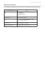
For more information about Digi products, or for customer service and technical support, contact Digi International.
To Contact Digi International by:
Use:
Mail
Digi International
11001 Bren Road East
Minnetonka, MN 55343
U.S.A.
World Wide Web:
http://www.digi.com/support/
email
Look for the link Contact Digi Support at this address:
http://www.digi.com/support/
Telephone (U.S.)
(952) 912-3444 or (877) 912-3444
Telephone (other locations)
+1 (952) 912-3444 or (877) 912-3444
7
Important Safety Information
Introduction
C
H
A
P
T
E
R
1
This chapter introduces Digi devices and their product families, types of connections and data
paths in which Digi devices can be used, and the interface options available for configuring,
monitoring, and administering Digi devices.
Important Safety Information
To avoid contact with electrical current:
Never install electrical wiring during an electrical storm.
Never install an Ethernet connection in wet locations unless that connector is
specifically designed for wet locations.
Use caution when installing or modifying lines.
Use a screwdriver and other tools with insulated handles.
Wear safety glasses or goggles.
Do not place Ethernet wiring or connections in any conduit, outlet or junction box
containing electrical wiring.
Installation of inside wire may bring you close to electrical wire, conduit, terminals and
other electrical facilities. Extreme caution must be used to avoid electrical shock from
such facilities. Avoid contact with all such facilities.
Ethernet wiring must be at least 6 feet from bare power wiring or lightning rods and
associated wires, and at least 6 inches from other wire (antenna wires, doorbell wires,
wires from transformers to neon signs), steam or hot water pipes, and heating ducts.
Do not place an Ethernet connection where it would allow a person to use an Ethernet
device while in a bathtub, shower, swimming pool, or similar hazardous location.
Protectors and grounding wire placed by the service provider must not be connected to,
removed, or modified by the customer.
Do not touch uninsulated Ethernet wiring if lightning is likely!
External Wiring: Any external communications wiring installed needs to be constructed
to all relevant electrical codes. In the United States this is the National Electrical Code
Article 800. Contact a licensed electrician for details.
For ConnectPort X4 H only: the plug serves as a disconnect device, and must be easily
accessible after the device is installed.
8
ConnectPort® X products
ConnectPort ® X products
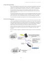
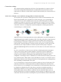
The ConnectPort X Family of products is intended to provide gateway functionality between
various network technologies such as Ethernet, cellular, Wi-Fi, and XBee. In addition to providing
IP network connectivity between cellular, Wi-Fi and Ethernet networks and devices; ConnectPort
X Family products are designed to provide remote connectivity to XBee networks as well as other
devices connected to local ports: USB, 1-Wire, RabbitNet, and asynchronous serial. ConnectPort X
Family products act as a coordinator for a mesh network. As with the Connect and Cellular product
families, ConnectPort X Family products are supported by Device Manager, which can be used to
remotely manage gateway devices and mesh networks.
Key features of ConnectPort X Family include:
Network flexibility: gateway functionality for a variety of networks
XBee-PRO Radio
Currently Freescale-based, primarily 802.15.4
Ember-250/XBee-based
Commercial/Industrial Grade
Device Manager™: High-level and detailed views of XBee networks and nodes
Personal Area Network (PAN) connectivity and management
Support of Python programming language, for creating a variety of embedded programs
and applications
Remote help desk support through a WatchPort® Camera connection to a USB host port
Security
For some models, an internal GPS
9
Features
Features
This is an overview of key features in Digi devices. Firmware features are covered in more detail in
the next three chapters. Hardware specifications are covered in Chapter 6, "Specifications and
certifications"
User interfaces
There are several user interfaces for configuring and monitoring Digi devices, including the
following.
Device Manager™
A web-based interface for configuring, monitoring, and administering Digi devices. For
Digi devices that ship with a default IP address, simply connecting a laptop computer to
the Ethernet port of these products allows direct access to the web interface for
configuration.
A command-line interface available via local serial port, telnet or SSH.
Simple Network Management Protocol (SNMP).
Configurable network services
Access to network services can be enabled and disabled. This means that a device’s use of network
services can be restricted to those strictly needed by the device. To improve device security, nonsecure services can be disabled. Network services that can be enabled or disabled include:
Advanced Digi Discovery Protocol (ADDP): can enable or disable ADDP, but cannot
change its network port number.
RealPort
Encrypted RealPort
HTTP/HTTPS
Line Printer Daemon (LPD)
Remote Login (rlogin)
Remote Shell (rsh)
Simple Network Management Protocol (SNMP)
Telnet
In the web interface, access to network services is enabled and disabled on the Network Services
page of Network Configuration. For more information, see "Network services settings" on page 64.
In the command-line interface, network services are enabled and disabled through the set service
command. See the Digi Connect Family Command Reference for the set service command
description.
10
Features
IP protocol support
All Digi devices include a Robust on-board TCP/IP stack with a built-in web server. Supported
protocols include, unless otherwise noted:
Transmission Control Protocol (TCP)
User Datagram Protocol (UDP)
Dynamic Host Configuration Protocol (DHCP)
Simple Network Management Protocol (SNMP)
Secure Sockets Layer (SSL)/Transport Layer Security (TLS)
Telnet Com Port Control Option (Telnet) including support of RFC 2217 (ability to
control serial port through Telnet). See "Serial data communication over TCP and UDP"
on page 12 for additional information.
Remote Login (rlogin)
Line Printer Daemon (LPD)
HyperText Transfer Protocol (HTTP)/HyperText Transfer Protocol over Secure Socket
Layer (HTTPS)
Simple Mail Transfer Protocol (SMTP)
Internet Control Message Protocol (ICMP)
Internet Group Management Protocol (IGMP)
Address Resolution Protocol (ARP)
Advanced Digi Discovery Protocol (ADDP)
Point to Point Protocol (PPP)
Network Address Translation (NAT)/Port Forwarding
Secure Shell (SSHv2)
Generic Routing Encapsulation (GRE) Passthrough
IPSec Encapsulating Security Payload (ESP) on most models
ESP Passthrough
Following is an overview of some of the services provided by these protocols.
11
Features
Serial data communication over TCP and UDP
Digi devices support serial data communication over TCP and UDP. Key features include:
Serial data communication over TCP, also known as autoconnect and tcpserial can
automatically perform the following functions:
–
Establish bidirectional TCP connections, known as autoconnections, between the serial
device and a server or other network device. Autoconnections can be made based on
data and or serial hardware signals.
–
Control forwarding characteristics based on size, time, and pattern
–
Allow incoming raw, Telnet, and SSL/TLS (secure-socket) connections
–
Support RFC 2217, an extension of the Telnet protocol
Serial data communication over UDP, also known as udpserial, can automatically
perform the following functions:
–
Digi Connect products can automatically send serial data to one or more devices or
systems on the network using UDP sockets. Options for sending data include whether
specific data is on the serial line, a specific time period has elapsed, or after the specified
number of bytes has been received on the serial port.
–
Control forwarding characteristics based on size, time, and patterns.
–
Support incoming datagrams from multiple destinations.
–
Support outgoing datagrams sent to multiple destinations.
TCP/UDP forwarding characteristics.
Extended communication control on TCP/UDP data paths.
–
Timeout
–
Hangup
–
User-configurable Socket ID string (text string identifier on autoconnect only)
Dynamic Host Configuration Protocol (DHCP)
Dynamic Host Configuration Protocol (DHCP) can be used to automatically assign IP addresses,
deliver TCP/IP stack configuration parameters such as the subnet mask and default router, and
provide other configuration information. For further details, see "Configure an IP address using
DHCP" on page 44.
Auto-IP
Auto-IP is a protocol that will automatically assign an IP address from a reserved pool of standard
Auto-IP addresses to the computer on which it is installed. For Digi devices are set to obtain its IP
address automatically from a DHCP server and the DHCP server is unavailable or nonexistent,
Auto-IP will assign the device an IP address. For further details, see "Configure an IP address using
Auto-IP" on page 45.
12
Features
Simple Network Management Protocol (SNMP)
Simple Network Management Protocol (SNMP) is a protocol for managing and monitoring
network devices. SNMP architecture enables a network administrator to manage nodes--servers,
workstations, routers, switches, hubs, etc.--on an IP network; manage network performance, find
and solve network problems, and plan for network growth. Digi devices support SNMP Versions 1
and 2. For more information on SNMP as a device-management interface, see "Simple Network
Management Protocol (SNMP)" on page 30. For a list SNMP-related of supported Request for
Comments (RFCs) and Management Information Bases (MIBs), see page 159.
Secure Sockets Layer (SSL)/Transport Layer Security (TLS)
Secure Sockets Layer (SSL)/Transport Layer Security (TLS) are used to provide authentication and
encryption for Digi devices. For more information, see "Security features in Digi devices" on page
18.
Telnet
Digi devices support the following types of Telnet connections:
Telnet Client
Telnet Server
Reverse Telnet, often used for console management or device management
Telnet Autoconnect
RFC 2217, Telnet Com Port Control Option, an extension of the Telnet protocol
For more information on these connections, see "Supported connections and data paths in Digi
devices" on page 20. Access to Telnet network services can be enabled or disabled.
Remote Login (rlogin)
Users can perform logins to remote systems (rlogin). Access to rlogin service can be enabled or
disabled.
Line Printer Daemon (LPD)
The Line Printer Daemon (LPD) allows network printing over a serial port. Each serial port has a
dedicated LPD server that is independently configurable. Access to LPD service can be enabled or
disabled.
HyperText Transfer Protocol (HTTP)
HyperText Transfer Protocol over Secure Socket Layer (HTTPS)
Digi devices provide web pages for configuration that can be secured by requiring a user login.
Internet Control Message Protocol (ICMP)
ICMP statistics can be displayed, including the number of messages received, bad messages
received, and destination unreachable messages received.
13
Features
Point-to-Point Protocol (PPP)
The Point-to-Point Protocol (PPP) transports multi-protocol packets over point-to-point links. PPP
encapsulates the data packet, allows the server to inform the dial-up client of its IP address (or
client to request the IP address), authenticates the exchange, negotiates multiple protocols, and
reassembles the data packet for network communication. ConnectPort X Family devices support
PPP as the connection protocol from the Digi device to the cellular IP network with NAT (Network
Address Technology).
Network Address Translation (NAT)/Port Forwarding
Network Address Translation (NAT) reduces the need for a large amount of publicly known IP
addresses by creating a separation between publicly known and privately known IP addresses.
Advanced Digi Discovery Protocol (ADDP)
The Advanced Digi Discovery Protocol (ADDP) runs on any operating system capable of sending
multicast IP packets on a network. ADDP allows the system to identify all ADDP-enabled Digi
devices attached to a network by sending out a multicast packet. The Digi devices respond to the
multicast packet and identify themselves to the client sending the multicast.
ADDP communicates with the TCP/IP stack using UDP. The TCP/IP stack should be able to
receive multicast packets and transmit datagrams on a network.
Not all Digi devices support ADDP. Access to ADDP service can be enabled or disabled, but the
network port number for ADDP cannot be changed from its default.
Generic Routing Encapsulation (GRE) Passthrough
Encapsulating Security Payload (ESP)
ESP Passthrough
Generic Routing Encapsulation (GRE) and Encapsulating Security Payload (ESP) are routing
protocols that are used to route (tunnel) various types of information between networks.
GRE applies to the encapsulation of IP datagrams tunnelled through the internet. The encapsulation
includes security, typically in the form of IPSec (IP security), and is most commonly found in VPN
(Virtual Private Network) implementation. RFC (Request For Comment) 1701 and 1702 define
these standards.Similarly, ESP is used in conjunction with IPsec as a possible way of carrying IP
packets for a Virtual Private Network (VPN) setup. ESP is defined in RFC 2406.
In ESP Passthrough and GRE Passthrough, inbound IPsec ESP or GSP protocol traffic is
forwarded from to a VPN device connected to the Digi device’s Ethernet port.
Note: If an Auto-key Internet Key Exchange (IKE)-based VPN is used, UDP port 500 must also be
forwarded.
14
Features
Mobile/Cellular features and protocol support
Key cellular features in cellular-enabled Digi devices include:
GSM: GPRS, EDGE, UMTS, HSPA, SMS
CDMA: 1xRTT, Ev-DO (Revs 0 and A)
IPSec ESP / IKE
IP Pass-through, also known as bridge mode
3-5 Volt SIM card
Signal-strength LEDs
Provisioning wizard
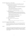
For Digi devices equipped with a Code-Division Multiple Access (CDMA)-based cellular modem,
the Mobile Device Provisioning Wizard is available in the web interface to properly configure the
Digi device with the required configuration used to access the mobile network. The wizard allows
for both automatic and manual provisioning for a variety of mobile service providers.
Digi SureLink™
Digi Connect Family, Digi Cellular Family, and ConnectPort X Family products support the Digi
SureLink™ feature. Digi SureLink provides an “always-on” mobile network connection to ensure
that a Digi device is in a state where it can connect to the network. It does this through hardware
reset thresholds and periodic tests of the connection.
Mobile/Cellular protocols
Mobile/cellular protocols supported include, unless otherwise noted:
Global System for Mobile communication (GSM)
General Packet Radio Service (GPRS)
Enhanced Data Rates for GSM Evolution (EDGE)
Universal Mobile Telecommunications Service (UMTS)
High Speed Packet Access (HSPA)
Code-Division Multiple Access (CDMA)
Evolution-Data Optimized (EV-DO, EVDO, or 1xEV-DO)
Short Message Service (SMS), currently for GSM cellular products only. Digi cellular
gateways implement an SMS-based protocol that allows managing devices by sending
SMS commands from anywhere SMS messages can be sent. See "Short Message
Service (SMS) settings" on page 114.
Wi-MAX
15
Features
RealPort software
Digi devices use the patented RealPort COM/TTY port redirection for Microsoft Windows.
RealPort software provides a virtual connection to serial devices, no matter where they reside on
the network. The software is installed directly on the host PC and allows applications to talk to
devices across a network as though the devices were directly attached to the host. Actually, the
devices are connected to a Digi device somewhere on the network. RealPort is unique among COM
port re-directors because it is the only implementation that allows multiple connections to multiple
ports over a single TCP/IP connection. Other implementations require a separate TCP/IP
connection for each serial port. Unique features also include full hardware and software flow
control, as well as tunable latency and throughput. Access to RealPort services can be enabled or
disabled.
Encrypted RealPort
Digi devices also support RealPort software with encryption. Encrypted RealPort offers a secure
Ethernet connection between the COM or TTY port and a device server or terminal server.
Encryption prevents internal and external snooping of data across the network by encapsulating the
TCP/IP packets in a Secure Sockets Layer (SSL) connection and encrypting the data using
Advanced Encryption Standard (AES), one of the latest, most efficient security algorithms. Access
to Encrypted RealPort services can be enabled or disabled. Digi’s RealPort with encryption driver
has earned Microsoft’s Windows Hardware Quality Lab (WHQL) certification. Drivers are
available for a wide range of operating systems, including Microsoft Windows Server 2003,
Windows XP, Windows 2000, Windows NT, Windows 98, Windows ME; SCO Open Server;
Linux; AIX; Sun Solaris SPARC; Intel; and HP-UX. It is ideal for financial, retail/point-of-sale,
government or any application requiring enhanced security to protect sensitive information.
16
Features
Alarms
Digi devices can be configured to issue alarms, in the form of email message or SNMP traps, when
certain device events occur. These events include certain data patterns being detected in the data
stream, and cellular alarms for signal strength and amount of cellular traffic for a given period of
time. Receiving alarms about these conditions provides the advantage of notifications being issued
when events occur, rather than having to monitor the device on an ongoing basis to determine
whether these events have occurred. Alarms can also be forwarded to Device Manager for display
and management in that platform. For more information on configuring alarms, see "Alarms" on
page 151.
Modem emulation
Digi devices include a configuration profile that allows the device to emulate a modem. Modem
emulation sends and receives modem responses to a serial device over TCP/IP (including Ethernet
and Cellular instead of Public Switched Telephone Network (PSTN). The modem emulation profile
allows maintaining a current software application but using it over the less expensive Ethernet
network. In addition, Telnet processing can be enabled or disabled on the incoming and outgoing
modem-emulation connections.The modem-emulation commands supported in Digi devices are
documented in the Digi Connect Family Command Reference.
17
Features
Security features in Digi devices
Secure access and authentication
One password, one permission level.
Passwords can be issued to device users.
Selective enabling/disabling network services such as ADDP, RealPort, Encrypted
RealPort, HTTP/HTTPS, LPD, Remote Login, Remote Shell, SNMP, and Telnet.
Can control access to inbound ports.
Can control access to specific devices, IP addresses, or networks through IP filtering.
Secure sites for configuration: HTML pages for configuration have appropriate security.
Encrypted RealPort offers encryption for the Ethernet connection between the COM/
TTY port and the Digi device. Encryption prevents internal and external snooping of
data across the network by encapsulating the TCP/IP packets in a Secure Sockets Layer
(SSL) connection and encrypting the data using the Advanced Encryption Standard
(AES) security algorithm.
Strong Secure Sockets Layer (SSL) V3.0/ Transport Layer Security (TLS) V1.0-based
encryption: DES (64-bit), 3DES (192-bit), AES (128-/192-/256-bit), IPsec ESP: DES,
3DES, AES.
Wireless Digi Connect products provide Wi-Fi Protected Access (WPA/WPA2/802.11i)
and Wired Equivalent Privacy (WEP) encryption (64-/128-bit). Supported WPA/WPA2/
802.11i authentication methods are:
Encryption
Supported WPA authentication methods
EAP-TLS
LEAP
(WEP only)
PEAP
EAP/TTLS
EAP-PEAP/MSCHAPv2 (both PEAPv0 and
PEAPv1)
EAP-PEAP/TLS (both PEAPv0 and PEAPv1)
EAP-PEAP/GTC (both PEAPv0 and PEAPv1)
EAP-PEAP/OTP (both PEAPv0 and PEAPv1)
EAP-PEAP/MD5-Challenge (both PEAPv0 and
PEAPv1)
EAP-TTLS/EAP-MD5-Challenge
EAP-TTLS/EAP-GTC
EAP-TTLS/EAP-OTP
EAP-TTLS/EAP-MSCHAPv2
EAP-TTLS/EAP-TLS
EAP-TTLS/MSCHAPv2
EAP-TTLS/MSCHAP
EAP-TTLS/PAP
EAP-TTLS/CHAP
18
Features
SNMP security
SNMP “set” commands can be disabled to make use of SNMP read-only. Changing public and
private community names is recommended to prevent unauthorized access to the device.
Network Port Scan Cloaking
The Network Port Scan Cloaking feature allows you to configure this Digi device to ignore
(discard) received packets for services that are hidden or not enabled and network ports that are not
open. This feature can be used to protect your Digi device from malicious software or denial of
service attacks. For more information, see "Network Port Scan Cloaking" on page 97.
Configuration management
Once a Digi device is configured and running, configuration-management tasks need to be
periodically performed, such as:
Upgrading firmware
Copying configurations to and from a remote host
Software and factory resets
Rebooting the device
Memory management
File management
For more information on these configuration-management tasks, see Chapter 5, "Device
administration".
Customization capabilities
Several aspects of using Digi devices can be customized. For example:
The look-and-feel of the device interface can be customized, to use a different company
logo or screen colors.
Custom applications written in Python can be executed.
Custom factory defaults to which devices can be reverted can be defined.
The Digi Connect Family Customization and Integration Guide (Part Number 90000734; available
with the Digi Connect Integration Kit) describes customization and integration tools and processes.
Contact Digi International for more information on the Digi Connect Integration Kit customization
tools and resources and for assistance with customization efforts.
19
Supported connections and data paths in Digi devices
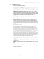
Supported connections and data paths in Digi devices
Digi devices allow for several kinds of connections and paths for data flow between the Digi device
and other entities. These connections can be grouped into two main categories:
Network services, in which a remote entity initiates a connection to a Digi device.
Network/serial clients, in which a Digi device initiates a network connection or opens a
serial port for communication.
This discussion of connections and data paths may be helpful in understanding the effects of
enabling certain features and choosing certain settings when configuring Digi products.
Network services
A network service connection is one in which a remote entity initiates a connection to a Digi
device. There are several categories of network services:
Network services associated with specific serial ports
Network services associated with serial ports in general
Network services associated with the command-line interface (CLI)
Network services associated with specific serial ports
Reverse Telnet: A telnet connection is made to a Digi device, in which data is passed
transparently between the telnet connection and a named serial port.
Reverse raw socket: A raw TCP socket connection is made to a Digi device, in which
data is passed transparently between the socket and a named serial port.
Reverse TLS socket: An encrypted raw TCP socket is made to a Digi device, in which
data is passed transparently to and from a named serial port.
LPD: A TCP connection is made to a named serial port, in which the Digi device
interprets the LPD protocol and sends a print job out of the serial port.
Modem emulation, also known as Pseudo-modem (pmodem): A TCP connection is
made to a named serial port, and the connection will be “interpreted” as an incoming call
to the pseudo-modem.
20
Supported connections and data paths in Digi devices
Network services associated with serial ports in general
RealPort: A single TCP connection manages (potentially) multiple serial ports.
Modem emulation, also known as pseudo-modem (pool): A TCP connection to the
“pool” port is interpreted as an incoming call to an available pseudo-modem in the
“pool” of available port numbers.
rsh: Digi devices support a limited implementation of the Remote shell (rsh) protocol, in
that a single service listens to connections and allows a command to be executed. Only
one class of commands is allowed: a single integer that specifies which serial port to
connect to. Otherwise, the resulting connection is somewhat similar to a reverse telnet or
reverse socket connection.
DialServ: Connecting a DialServ device to the serial port. DialServ simulates a public
switched telephone network (PSTN) to a modem and forwards the data to the serial port.
The Digi device sends and receives the data over an IP network.
Network services associated with the command-line interface
Telnet: A user can Telnet directly to a Digi device’s command-line interface.
rlogin: A user can perform a remote login (rlogin) to a Digi device’s command-line
interface.
21
Supported connections and data paths in Digi devices
Network/serial clients
A network/serial client connection is one in which a Digi device initiates a network connection or
opens a serial port for communication. There are several categories of network/serial client
connections:
Autoconnect behavior client connections
Command-line interface (CLI)-based clients
Modem emulation (pseudo-modem) client connections
Autoconnect behavior client connections
In client connections that involve autoconnect behaviors, a Digi device initiates a network
connection based on timing, serial activity, or serial modem signals. Autoconnect-related client
connections include:
Raw TCP connection: The Digi device initiates a raw TCP socket connection to a
remote entity.
Telnet connection: The Digi device initiates a TCP connection using the Telnet protocol
to a remote entity.
Raw TLS encrypted connection: The Digi device initiates an encrypted raw TCP
socket connection to a remote entity.
Rlogin connection: The Digi device initiates a TCP connection using the rlogin
protocol to a remote entity.
Command-line interface (CLI)-based client connections
Command-line interface based client connections are available for use once a user has established a
session with the Digi device’s CLI. CLI-based client connections include:
telnet: A connection is made to a remote entity using the Telnet protocol.
rlogin: A connection is made to a remote entity using the Rlogin protocol.
connect: Begin communicating with a local serial port.
Modem emulation (pseudo-modem) client connections
When a port is in the modem-emulation or pseudo-modem mode, it can initiate network
connections based on AT command strings received on the serial port.The AT commands for
modem emulation are documented in the Digi Connect Family Command Reference.
22
Interfaces for configuring, monitoring, and administering Digi devices
Interfaces for configuring, monitoring, and administering Digi devices
There are several interfaces for configuring, monitoring, and administering Digi devices. These
interfaces are covered in more detail later in this guide.
Configuration capabilities
Device configuration involves setting values and enabling features for such areas as:
Network configuration: Specifying the device’s IP address settings, network-service
settings, and advanced network settings.
Mobile (cellular) configuration: Specifying the mobile service provider and mobile
connection settings for the device.
Serial port configuration: Specifying the serial port characteristics for the device.
Alarms: Defining whether alarms should be issued, the conditions that trigger alarms,
and how the alarms should be delivered.
Security/Users configuration: Configuring security features, such as whether password
authentication is required for device users.
System configuration: Specifying system-identifying information, such as a device
description, contact person, and physical location.
23
Interfaces for configuring, monitoring, and administering Digi devices
Configuration interfaces
Several interfaces are available for configuring Digi devices, including:
The Digi Device Discovery Utility, which locates Digi devices on a network, and allows
opening the web interface for the devices.
Device Manager, a configuration interface to fine-tune or monitor devices. Device
Manager cannot assign an IP address but it can change one.
A web-based interface embedded with the product, providing device configuration
profiles for quick serial-port configuration and other settings.
A command-line interface (CLI).
Remote Command-line Interface (RCI) protocol
Simple Network Management Protocol (SNMP).
24
Interfaces for configuring, monitoring, and administering Digi devices
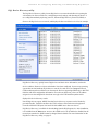
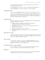
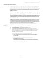
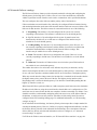
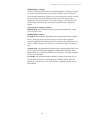
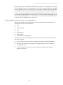
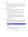
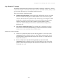
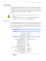
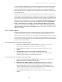
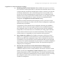
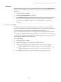
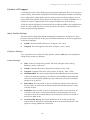
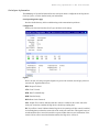
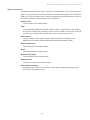
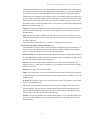
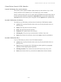
Digi Device Discovery utility
The Digi Device Discovery utility locates Digi devices on a network and allows for opening the
web interface for discovered devices, configuring network settings, and rebooting the device. It
uses a Digi International-proprietary protocol, Advanced Digi Discovery Protocol (ADDP), to
discover the Digi devices on a network, and displays the discovered devices in a list, for example:
Digi Device Discovery quickly locates Digi devices and basic device information, such as the
device’s address, firmware revision, and whether it has been configured. It runs on any operating
system that can send multicast IP packets to a network. It sends out a User Datagram Protocol
(UDP) multicast packet to all devices on the network. Devices supporting ADDP reply to this UDP
multicast with their configuration information. Even devices that do not yet have an IP address
assigned or are misconfigured for the subnet can reply to the UDP multicast packet and be
displayed in device discovery results.
Not all Digi devices support ADDP. Note that Device discovery responses can be blocked by
personal firewalls, Virtual Private Network (VPN) software, and certain network equipment.
Firewalls will block UDP ports 2362 and 2363 that ADDP uses to discover devices.
Digi Device Discovery is available for downloading from the Digi Support site. After installation,
it is available from the Start menu. Access to the ADDP service can be enabled or disabled, but the
network port number for ADDP cannot be changed from its default. For more information on the
Digi Device Discovery utility, see page 47.
25
Interfaces for configuring, monitoring, and administering Digi devices
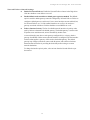
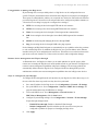
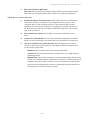
Device Manager™ interface
Device Manager is a software-as-a-service, delivering capabilities that empower IT, network
operations and customer support organizations to conquer the challenges of managing the vast
array of equipment in their device networks. As a network grows, the complexity of effectively
managing the network assets grows exponentially. Hosted on the Device Cloud by Etherios™,
Device Manager directly tackles and conquers the universal problems of a dynamic device
network:
Centralized control over large numbers of devices
Reducing service complexity
Maintaining high levels of security
Provisioning and decommissioning of equipment
Adding functionality to device networks
A feature of all Digi gateways, routers, devices and components, Device Manager provides a
robust suite of network management tools with centralized control via the Device Manager service
module.
From the Device Manager interface, you can configure devices, remotely update device firmware,
upload and manage Python/DIA files, remotely reboot devices, reset devices to factory defaults,
backup/restore device configuration properties, import or export the device configuration
properties, track devices, monitor devices and connections.
With Device Manager, management of large populations of devices is made easy. Devices can be
tagged and grouped together enabling management tasks to groups of devices within a network
simultaneously. Furthermore, the Scheduled Operations feature allows device management tasks to
26
Interfaces for configuring, monitoring, and administering Digi devices
be automated and scheduled to run either on a one-time or a recurring basis, against a single device
or multiple devices. The Alarms capability of Device Manager facilitates monitoring the health of a
device network. For instance, should a device disconnect or stay connected for longer than a
specified period, an alarm fires and notification of the alarm can be sent via email in real-time.
Some things to note about using Device Manager:
Devices must be registered on Device Manager before they can be accessed via the
Device Cloud platform.
To minimize network traffic, Device Manager uses caching. As a result, device settings
can be out-of-sync between the device and the settings viewed on the Device Manager
console.
Device information can be refreshed on demand when the device is connected, and is
refreshed automatically when a device connects.
For more information on Device Manager as a remote device network management solution, see
these resources:
Device Cloud User’s Guide
Device Cloud Programming Guide
Device Cloud tutorials and other documents available on www.etherios.com/
devicecloud
27
Interfaces for configuring, monitoring, and administering Digi devices
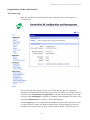
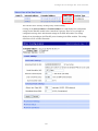
Web interface
A web interface is provided as an easy way to configure and monitor Digi devices. Configurable
features are grouped into several categories. These categories vary by product; examples include
Network, Serial Port,Alarms, and System. Most of the configurable features are arranged by most
basic settings on a page, with associated and advanced settings accessible from that page. Serial-port
configurations are classified into port profiles, or configuration scenarios that best represents the
environment in which the Digi device will be used. Selecting a particular port profile configures the
serial port parameters that are needed. To access the web interface, enter the Digi device’s IP
address or host name in a browser’s URL window. The main menu of the web interface is
displayed. For more information, see "Configuration through the web interface" on page 47. The
web interface has a tutorial, accessed from the Home page, and online help, accessed from the Help
link on each page. Not all settings provided by the command-line interface are displayed in the web
interface. However, the configuration settings in the web interface should be sufficient for most
users. If necessary, settings can be modified later from the command line.
28
Interfaces for configuring, monitoring, and administering Digi devices
Command-line interface
Digi devices can be configured by issuing commands from the command line. The command-line
interface allows communication directly without a graphical interface. To access the command line
from the Digi Device Discovery utility, click Telnet to command line.
For example, here is a command issued from the command line to assign the IP address to the
Ethernet interface:
#> set network ip=192.168.1.1
The command-line interface provides flexibility for making precise changes to device
configuration settings and operation. It does require users to have experience issuing commands,
and access to command documentation.
The command line is available through Telnet or SSH TCP/IP connections, or through serial port
using terminal emulation software such as Hyperterminal. Access to the command line from serial
ports depends on the port profile in use by the port. By default, serial port command-line access is
allowed.
See "Configuration through the command line" on page 191 for more information on this interface.
See the Digi Connect Family Command Reference for command descriptions and examples of
entering configuration commands from the command-line interface. In addition, online help is
available for the commands, through the help and ‘?’ commands.
Remote Command Interface (RCI)
Remote Command Interface (RCI) is a programmatic interface for configuring and controlling Digi
devices. RCI is an XML-based request/response protocol that allows a caller to query and modify
device configurations, access statistics, reboot the device, and reset the device to factory defaults.
Unlike other configuration interfaces that are designed for a user, such as the command-line or web
interfaces, RCI is designed to be used by a program. RCI access consists of program calls. A
typical use of RCI is in a Java applet that can be stored on the Digi device to replace the web
interface with a custom browser interface. Another example is a custom application running on a
PC that monitors and controls an installation of many Digi devices.
As RCI is designed to be used by a program, it is useful for creating a custom configuration user
interface, or utilities that configure or initialize devices through external programs or scripts.
RCI uses HTTP as the underlying transport protocol. Depending on the network configuration, use
of HTTP as a transport protocol could be blocked by some firewalls.
RCI is quite complex to use, requiring users to phrase configuration requests in Extensible Markup
Language (XML) format. It is a “power-user” option, intended more for users developing their own
user interfaces, or for users implementing embedded control (and thus potentially using RCI over
serial) than for end-users with limited knowledge of device programming.
Not all actions in the web interface have direct equivalents in RCI. Therefore, it may not be easy
for some end-users to determine what needs to be sent through XML for a particular style of
request.
For more details on RCI, see the Digi Connect Integration Kit and the Remote Command Interface
(RCI) Specification.
29
Interfaces for configuring, monitoring, and administering Digi devices
Simple Network Management Protocol (SNMP)
Simple Network Management Protocol (SNMP) is a protocol for managing and monitoring
network devices. The SNMP architecture enables a network administrator to manage nodes-servers, workstations, routers, switches, hubs, etc.--on an IP network; manage network
performance, find and solve network problems, and plan for network growth. Digi devices support
SNMP Versions 1 and 2.
SNMP is easy to implement in extensive networks. Programming new variables and “dropping in”
new devices in a network are easy. SNMP is widely used. It is a standard interface that integrates
well with network management stations in an enterprise environment. While its capabilities are
limited to device monitoring and display of statistics in Digi devices, read/write capabilities are
expected to be added to Digi devices in future releases.
However, because device communication is UDP-based, the communication is not secure. If more
secure communications with a device are required, use an alternate device interface. SNMP does
not allow for certain task that can be performed from the web interface, such as file management,
uploading firmware, or backing up and restoring configurations. Compared to the web or
command-line interfaces, SNMP is limited in its ability to set specific parameters, such as set port
profile, is not possible.
Accessing the SNMP interface requires a tool, such as a network management station. The
management station relies on an agent at a device to retrieve or update the information at the
device, including Device configuration, status, and statistical information. This information is
viewed as a logical database, called a Management Information Base (MIB). MIB modules
describe MIB variables for a variety of device types and computer hardware and software
components.
A variety of resources about SNMP are available, including reference books, overviews, and other
files on the Internet. For an overview of the SNMP interface and the components of MIB-II, go to
http://www.rfc-editor.org/rfcsearch.html, and search for MIB-II. From the results, locate the text
file describing the SNMP interface, titled Management Information Base for Network
Management of TCP/IP-based internets: MIB-II. The text of the Digi enterprise MIBs can also be
displayed.
For additional discussion of using SNMP as a device monitoring interface, see "Monitoring
Capabilities from SNMP" on page 229.
30
Interfaces for configuring, monitoring, and administering Digi devices
Monitoring capabilities and interfaces
Monitoring Digi devices includes such tasks as checking device status, checking runtime state,
viewing serial port operations, and reviewing network statistics, and managing their connections.
There are several interfaces for monitoring Digi devices and managing their connections.
As with device configuration, there are several interfaces available for monitoring Digi devices,
including, the web interface embedded with the product, SNMP, command-line interface, and
Device Manager. These interfaces are covered in more detail in Chapter 4, "Monitoring and
management"
Device Manager
In Device Manager, monitoring capabilities can be sorted by the server and the devices managed by
the server. The information is available in logs and can be generated into reports. When available,
the reports post linked totals that can be drilled back to the original devices that make up the
activity of the report.
Device Manager is well-suited to managing ConnectPort X Family devices and the networks in
which the devices reside. Advantages include the ability to view an entire network, and multiple
networks, at once, and ease in viewing signal strength, link quality, and alarms
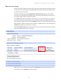
Web interface
The web interface has several screens for monitoring Digi devices:
Network Status
Mobile connection status
Serial Port Management: for each port, the port’s description, current profile, and current
serial configuration.
Connections Management: A display of all active system connections.
System Information: general device information; serial port information for each port,
including the port’s description, current profile, and current serial configuration (the
same information displayed by choosing Serial Port Management); and network
statistics.
Command-line interface
Several commands can be issued from the command line to monitor devices. For a review of these
commands and what they can provide from a device-monitoring perspective, see "Monitoring
capabilities from the command line" on page 225.
SNMP
Monitoring capabilities of SNMP include managing network performance, gathering device
statistics, and finding and solving network problems. For more information on using SNMP for
device-monitoring purposes, see "Monitoring Capabilities from SNMP" on page 229.
31
Interfaces for configuring, monitoring, and administering Digi devices
Device administration
Periodically, administrative tasks need to be performed on Digi devices, such as uploading and
managing files, changing the password for logging onto the device, backing up and restoring
device configurations, updating firmware, restoring the configuration to factory defaults, and
rebooting.
As with configuration and monitoring, administration can be done from a number of interfaces,
including the web interface, command line, and Device Manager. See Chapter 5, "Device
administration" for more information and procedures.
32
Hardware
C
H
A
P
T
E
R
2
This section details requirements and recommendations for installing ConnectPort X Family
product hardware. See also "Specifications and certifications" on page 252 and "System status
LEDs" on page 266.
33
Hardware installation for ConnectPort X4 H
Hardware installation for ConnectPort X4 H
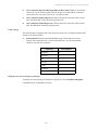
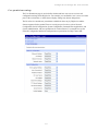
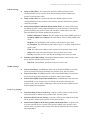
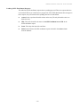
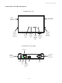
Connector pinouts
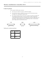
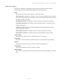
The ConnectPort X4 H has three connectors.
The 2-pin power connector is properly wired before shipping.
The 9-pin RS-232, RS-422, and RS-485 connector must be wired by the customer
according to the wiring diagram and pinout table.
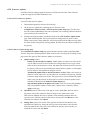
The 14-pin input/output connector must also be wired by the customer according to the
wiring diagram and pinout table. If you have purchased a 2-analog 2-digital input
version of this product, Input/Output 1 and Input/Output 2 are the two analog inputs, and
Input/Output 3 and Input/Output 4 are the two digital inputs. Pins 13 and 14 provide
power and ground for an optional Ethernet hub.
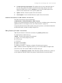
2-pin power connector pinouts
Pin
Function
1
+9 to 30 VDC
N
2
GND
34
Hardware installation for ConnectPort X4 H
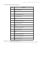
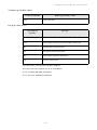
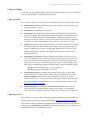
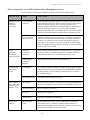
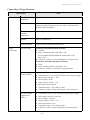
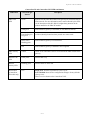
9-pin RS-232, RS-422, and RS-485 connector pinouts
RS-232
Pin
RS-422
Function
Pin
RS-485
Function
Pin
Function
1
CD
1
CTS(-)
1
CTS(-)
2
RXD
2
RXD(+)
2
485(+)
3
TXD
3
TXD(+)
3
N/A
4
DTR
4
RTS(-)
4
RTS(-)
5
GND
5
GND
5
GND
6
DSR
6
RXD(-)
6
485(-)
7
RTS
7
RTS(+)
7
RTS(+)
8
CTS
8
CTS(+)
8
CTS(+)
9
RI
9
TXD(-)
9
N/A
35
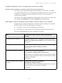
Hardware installation for ConnectPort X4 H
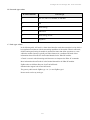
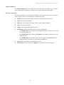
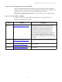
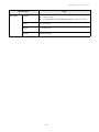
14-pin input/output connector pinouts
Pin
Function
1
+24VDC sensor power
2
GND
3
Analog/Digital Input/Output 1
4
+24VDC sensor power
5
GND
6
Analog/Digital Input/Output 2
7
+24VDC sensor power
8
GND
9
Analog/Digital Input/Output 3
10
+24VDC sensor power
11
GND
12
Analog/Digital Input/Output 4
13
+24VDC for auxiliary power
14
GND for auxiliary power
Maximum power usage on sensor power lines
A maximum of 300mA can be shared between all 5 24V power taps on the 14-pin connector.
36
Hardware installation for ConnectPort X4 H
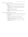
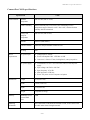
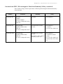
Analog and digital I/O specifications
The number of analog and digital input/output ports varies among ConnectPort X4 H models.
There are three basic variants:
4 analog I/O
4 digital I/O
2 analog I/O / 2 digital I/O
Specifications for the analog and digital I/O follow.
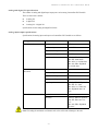
Analog input/output specifications
Specifications for analog input and output on ConnectPort X4 H models are as follows:
Analog Mode
Specification
Value
0-10 volt mode
Minimum input
0 VDC
Maximum input
+10.25 VDC
Minimum safe input
-0.5 VDC
Maximum safe input
+11 VDC
Input impedance
Differs by XBee RF protocol:
XBee ZB: 28200 ohms
XBee 802.15.4: 43600 ohms
XBee 868, XBee DigiMesh
900: 43600 ohms
Minimum input
0 mA
Maximum input
23.5 mA
Minimum safe input
-.5 VDC
Maximum safe input
40 mA
Input impedance
Differs by XBee RF protocol:
XBee ZB: 51.1 ohms
XBee 802.15.4:, XBee 868,
XBee DigiMesh 900: 120
ohms
Resolution
10 bits
Accuracy
Differs by XBee RF protocol:
XBee ZB, XBee 802.15.4:
0.2%
XBee 868, XBee DigiMesh
900: 0.4%
Current Loop (4 mA to 20
mA) mode
All modes
Note: Exceeding the maximum or minimum safe values will result in damage to the unit.
37
Hardware installation for ConnectPort X4 H
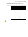
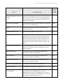
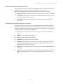
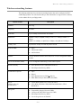
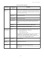
Digital input/output specifications
Specifications for digital input and output on ConnectPort X4 H models are as follows:
Digital mode
Specification
Value
Digital Input
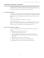
Input type
Non-inverting Schmitt trigger gate
Positive-going switching threshold
~1.6 VDC
Negative-going switching threshold
~1.0 VDC
Minimum input
0 VDC
Maximum input:
+30 VDC
Minimum safe input
-0.5 VDC
Maximum safe input
+31 VDC
Input impedance
1.5 Megaohms
Default level when no input applied
Low
Output type
Open collector sinking driver
Maximum sink current
1.8 ADC
Minimum output voltage
0 VDC
Maximum output voltage
+30 VDC
Minimum safe output
-0.5 VDC
Maximum safe output
+31 VDC
Resistor pullups
10K ohms pulled up to 3VDC;
switch-selectable
Digital Output
Note: Exceeding the maximum or minimum safe input values will result in damage to the unit.
38
Hardware installation for ConnectPort X4 H
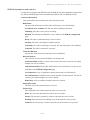
Cable fittings
To route serial, Ethernet or sensor cables outside the enclosure, and maintain IP66 rating, the three
hole plugs can be replaced with cable fittings, available in different diameters. These cable fittings
can be purchased separately from Digi.
To wire sensors through cable fittings:
1
Locate cord grip to attach sensor. Different diameter cord grips are available for different
sensors, please contact Digi for purchase.
2
Wire sensor to the 14-pin connector plug using the pinout guide provided in the enclosure or
in the pinout section on page 34. Up to 4 sensors can be wired into the 14-pin connector.
Note Make sure that all cable fittings are tightened and all empty holes are plugged before
use to maintain environmental rating.
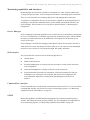
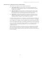
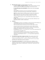
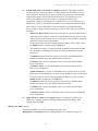
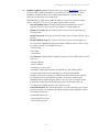
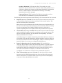
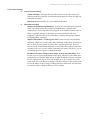
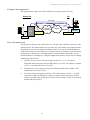
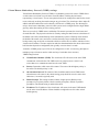
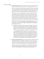
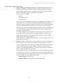
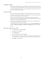
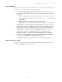
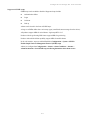
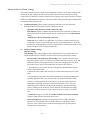
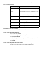
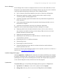
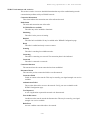
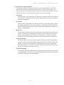
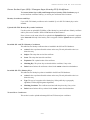
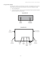
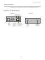
Antenna options and connectors
ConnectPort X4 H has two antenna connectors, one for cellular networks and the other for XBee
networks. Connect the antennas that come with the unit you purchased.
XBee Antenna
Connector
Cellular Antenna
Connector
c
Conne
4H
tPort X
Power cable
and conduit
Cable
Fittings
39
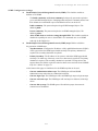
Hardware installation for ConnectPort X4 H
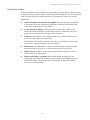
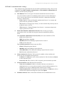
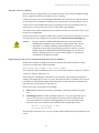
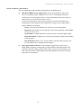
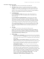
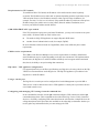
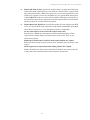
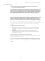
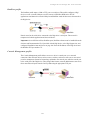
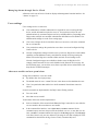
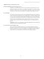
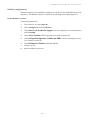
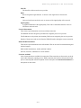
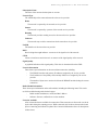
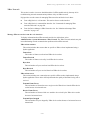
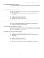
SIM card slots
There are two SIM card slots on the circuit board. If you are only using one SIM, insert it into the
primary SIM slot (the slot closer to the top of the product) as shown.
Note: For ConnectPort X4 H, the SIM cards slots are on the underside of NEMA enclosure cover.
When the cover is opened to insert the SIM card, the primary SIM card slot is the lower of the two
slots, and may be difficult to access for inserting the card. Consider using the secondary card slot.
The metal contacts on the SIM card should be facing down, and the chamfered edge should be
inserted first. When properly inserted, the SIM card will click into place. High-temperature SIM
cards are recommended to ensure cellular connectivity throughout the lifetime of the product.
SIM card activation
The SIM card must be activated for cellular service. Contact your mobile service provider and see
"Mobile (cellular) settings" on page 99.
40
Hardware installation for ConnectPort X4 H
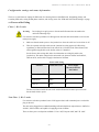
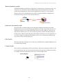
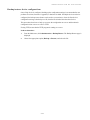
Configuration settings and status information
There are several firmware settings for SIM cards, for selecting between dual SIM cards, designating primary and
secondary SIM cards, setting ID and phone numbers, and viewing status. See "SIM card selection and settings" on page
100.Power
cable fitting
Class 1, Div 2 units
Warning
Do not plug in or apply power to the unit until all connections are made to the
unit in the following steps.
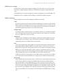
For customers who have purchased a C1D2-approved unit with cable and conduit to wire into the
main power supply:
1
Make sure that the mains power to the junction box where the cable is to be wired into is off.
2
Wire the exposed end of the cable into the junction box using approved C1D2 wiring
regulations per National Electrical Code Article 501 (if located in the United States) and
other regulations applicable to the locality where it is installed.
See the Power cable wiring table below for information on wiring this cable to the
junction box. The mains voltage for this unit needs to be between 100VAC and 240VAC,
50Hz to 60 Hz, and be able to supply a minimum of 24 Watts.
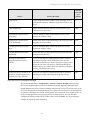
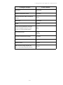
Power cable wiring
Function
Cable Wire Color
Power Supply
Phoenix Connector
Pin Number
Frame Ground (FG)
Green
1
Neutral (N)
White
2
Line (L)
Black
3
The blue reset button inside the unit can be used to disconnect/reconnect power for units
that are hard-wired to power.
Non-Class 1, Div 2 units
For customers who have purchased a non-C1D2 approved unit with a standard power cord with a
plug on the end:
The unit can be plugged into a standard matching wall outlet that has an output between 100VAC to
240VAC, 50Hz to 60Hz, and capable of supplying at least 24 Watts.
There are three power-cord options available: U.S.A 120V, European 240V, and U.K. 240V.
41
Hardware installation for ConnectPort X4 H
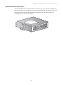
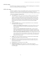
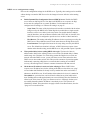
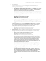
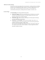
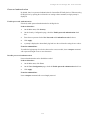
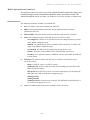
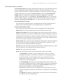
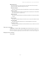
Optional Ethernet hub feature
The Ethernet hub for the ConnectPort X4 H is pre-wired to pins 13 and 14 of the 14-pin Phoenix
sensor connector for power and ground. It also comes with an Ethernet cable connecting one of the
five Ethernet ports to the Ethernet connector in the main board (any port can be used). The
remaining four ports can be used as desired.
42
Configuration
C
H
A
P
T
E
R
3
This chapter describes how to configure a Digi device. It covers these topics:
"IP address assignment" on page 44
"Configuration through Device Manager" on page 46
"Configuration through the web interface" on page 47
"Configuration through the command line" on page 191
"Configuration through Simple Network Management Protocol (SNMP)" on page 194
"Batch capabilities for configuring multiple devices" on page 194
43
IP address assignment
IP address assignment
Default IP address and DHCP settings
All products that have a cellular (WAN) interface ship with static IP address for the Ethernet port
of 192.168.1.1 and DHCP server enabled by default. Therefore, simply connecting a laptop
computer to the Ethernet port of these products allows direct access to the web interface for
configuration.The Ethernet port of the laptop should be configured to automatically receive an IP
address and DNS server address.
All products that only have an Ethernet or Wi-Fi (LAN) interface ship with DHCP client enabled
by default. Accessing the web interface on these products is most easily done by connecting it to a
LAN that has a DHCP server.
To discover which IP address has been assigned to the device, use the Device Discovery Utility for
Windows, available on the Digi Support site. See installation instructions on page 47.
Alternative methods of assigning IP addresses
There are several methods to assign an IP address to a Digi device, described on the following
pages:
Use Dynamic Host Configuration Protocol (DHCP) from the web interface.
Use the command-line interface.
Use Automatic Private IP Addressing (APIPA), also known as Auto-IP.
Configure an IP address using DHCP
An IP address can also be configured using Dynamic Host Configuration Protocol (DHCP). DHCP
is an Internet protocol for automating the configuration of computers that use TCP/IP. DHCP can
be used to automatically assign IP addresses and deliver TCP/IP stack configuration parameters.
As mentioned previously, all products that have a cellular (WAN) interface ship with static IP
address for the Ethernet port of 192.168.1.1 and DHCP server enabled by default. All products that
only have an Ethernet or Wi-Fi (LAN) interface ship with DHCP client enabled by default.
If desired, set up a permanent entry for the Digi device device on a DHCP server. While this is not
necessary to obtain an IP address via DHCP, setting up a permanent entry means the IP address is
saved when the device is rebooted. For more information on DHCP server configuration, see
"DHCP server settings" on page 60.
44
IP address assignment
Configure an IP address using Auto-IP
The standard protocol Automatic Private IP Addressing (APIPA or Auto-IP) automatically assigns
the IP address from a group of reserved IP addresses to the device on which Auto-IP is installed.
Use Digi Device Discovery or DHCP to find the Digi device and assign it a new IP address that is
compatible with your network. Once the unit is plugged in, Auto-IP automatically assigns the IP
address. Auto-IP addresses are typically in the 169.254.x.x address range.
Configure an IP address from the command-line interface
The set network command configures an IP address from the command line. Include the following
parameters:
ip=device ip: The IP address for the device.
gateway=gateway: The network gateway IP address.
submask=device submask: The device subnet mask.
dhcp=off: Turns off use of the Dynamic Host Configuration Protocol (DHCP), so that
the IP address assigned is permanent.
static=on: Specifies that the IP address is static, and will remain as the specified IP
address, gateway, and submask.
For example:
set network ip=10.0.0.100 gateway=10.0.0.1
submask=255.255.255.0 dhcp=off static=on
IP addresses and Device Manager
From the Device Manager interface, the Ethernet/LAN address for a Digi device can be changed
only; an address cannot be assigned. The mobile/cellular device is typically provided by the
mobile service provider; check with your mobile service provider on how they handle addresses.
To change the IP address, open the web interface for based on the IP address the device has and
navigate to Configuration > Network > IP Settings. On the IP Settings page, enter the new IP
address, subnet mask, and gateway.
Test the IP address configuration
Once the IP address is assigned, make sure it works as configured.
1
Access the command line of a PC or other networked device.
2
Issue the following command:
ping ip-address
where ip-address is the IP address assigned to the Digi device. For example:
ping 192.168.2.2
45
Configuration through Device Manager
Configuration through Device Manager
Device Manager is an on-demand service. After creating a Device Cloud account, you can connect
to Device Manager. There are no infrastructure requirements. Remote devices and enterprise
business applications connect to Device Manager via standards-based Web Services.
For details on using Device Cloud as a management interface, creating a Device Cloud account
and add your ConnectPort X Family device to the Device Manager device list so it can be managed
from that interface, see the Device Cloud User’s Guide.
Device Cloud device management through Short Message Service (SMS) commands
Digi devices can be configured to be managed by Device Cloud through Short Message Service
(SMS) commands. See "Users settings" on page 172.
46
Configuration through the web interface
Configuration through the web interface
Open the web interface
To open the web interface, either enter the Digi device’s URL in a web browser and log on to the
device, if required, or use the Digi Device Discovery utility to locate it and open its web interface.
By entering the Digi device’s IP address in a web browser
1
In the URL address bar of a web browser, enter the IP address of the device.
2
If security has not been enabled for the Digi device, the Home page of the web interface is
displayed. If security has been enabled for the Digi device, a login dialog will be displayed.
Enter the user name and password for the device. The default username is root and the
default password is dbps. If these defaults do not work, contact the system administrator
who set up the device. Then the Home page of the web interface is displayed. See
"Organization of the web interface" on page 49 for an overview of using the Home page and
other linked pages.
Note The idle timeout automatically logs users out of the web interface after 5 minutes of
inactivity if password authentication has been enabled for the device.
By using the Digi Device Discovery utility
Alternatively, use the Digi Device Discovery Utility to locate the Digi device and open its web
interface.
Install and run the Digi Device Discovery utility
The Digi Device Discovery Utility is available for downloading from the Digi Support site.
If this utility is not already available on your computer, follow these steps.
1
From a browser, go to www.digi.com.
2
Click the Support link and select Diagnostics, Utilities and MIBs.
3
Under Select Your Product for Support, select your Digi device from the product list
and click Submit.
4
Under Active Products, select your Digi device from the product list.
5
Under OS Specific Diagnostics, Utilities and MIBs, select the operating system for
your computer from the list.
6
Select either Device Discovery Utility for Windows - Standalone version or
Device Discovery Utility for Windows - Installable version. The standalone version runs
the utility immediately after the download is complete. The installable version installs the
utility on your computer and adds it to a program group named Digi in the Start menu.
7
Click Run on the two dialogs. The standalone version of the utility starts immediately.
For the installable version, an installation wizard is displayed. Follow the prompts to
complete the installation. To start the utility, select
Start > Programs > Digi > Digi Device Discovery > Digi Device Discovery
47
Configuration through the web interface
Discover devices
From the start menu, select Start > Programs > Digi Connect > Digi Device Discovery. The Digi
Device Discovery application is displayed.
Locate the device in the list of devices, and double-click it, or select the Digi device from the list
and select Open web interface in the Device Tasks list.
48
Configuration through the web interface
Organization of the web interface
The Home page
When the web interface is opened, the Home page is displayed. Here is a home page for a
ConnectPort X4.
The left side of the Home page has a menu of choices that display pages for configuration,
management, and administration tasks, and to log out of the web interface. This chapter focuses on
the choices under Configuration and Applications. For details on monitoring Digi devices and
the choices under Management, see Chapter 4, "Monitoring and management".For details on the
tasks under Administration, see Chapter 5, "Device administration".
Clicking Logout logs out of a configuration and management session with a Digi device. It does
not close the browser window, but displays a logout window. To finish logging out of the web
interface and prevent access by other users, close the browser window. Or, log back on to the
49
Configuration through the web interface
device by clicking the link on the screen. After 5 minutes of inactivity, the idle timeout also
automatically performs a user logout.
The Getting Started section has a link to a tutorial on configuring and managing Digi device.
The System Summary section notes all available device-description information.
Configuration pages
The choices under Configuration in the menu display pages for configuring settings for various
features, such as network settings, and serial port settings. Some of the configuration settings are
organized on sets of linked screens. For example, the Network Configuration screen initially
displays the IP Settings, and provides links to Network Services Settings, Advanced Settings, and
other network settings appropriate to the Digi device.
Applications pages
Depending on the Digi device, there may be an Applications menu item for configuring various
applications available for use in the device.
Python: For loading and running custom programs authored in the Python
programming language onto ConnectPort X Family devices.
Ekahau Client: For Digi Connect wireless devices, configures Ekahau Client™ devicelocation software. See page 188.
RealPort: Configures RealPort settings. See page 186.
Industrial Automation: Configures the Digi device for use in industrial automation
applications.
Apply and save changes
The web interface runs locally on the device, which means that the interface always maintains and
displays the latest settings in the Digi device. On each screen, the Apply button is used to save any
changes to the configuration settings to the Digi device.
Cancel changes
To cancel changes to configuration settings, click the Refresh or Reload button on the web
browser. This causes the browser to reload the page. Any changes made since the last time the
Apply button was clicked are reset to their original values.
Restore the Digi device to factory defaults
The device configuration can be reset to factory defaults as needed during the configuration
process. See "Restore a device configuration to factory defaults" on page 246.
Online help
Online help is available for all screens of the web interface, and for common configuration and
administration tasks. There is also tutorial available on the Home page.
50
Configuration through the web interface
Change the IP address from the web interface, as needed
Normally, IP addresses are assigned to Digi devices either through DHCP or the Digi Device Setup
Wizard.
This procedure assumes that the Digi device already has an IP address and you simply want to
change it.
1
Open a web browser and enter the Digi device’s current IP address in the URL address bar.
2
If security is enabled for the Digi device, a login prompt is displayed. Enter the user name
and password for the device. The default username is root and the default password is dbps.
If these defaults do not work, contact the system administrator who set up the device.
3
Click Network to access the Network Configuration page.
4
On the IP Settings page, select Use the following IP address.
5
Enter an IP address (and other network settings), then click Apply to save the configuration.
51
Configuration through the web interface
Network configuration settings
The Network configuration pages include:
Ethernet IP settings: For viewing IP address settings and changing as needed. See
page 55.
WiFi IP settings: For setting the IP address used for wireless LAN communication. See
page 56.
WiFi LAN settings: For setting basic options for wireless LAN devices such as
network name and network connection options. See page 56.
WiFi Security settings: For setting authentication and encryption options for wireless
LAN devices. See page 57.
WiFi 802.1x Authentication settings: Detailed authentication settings for IEEE 802.1x
authentication for wireless LAN devices. See page 59.
DHCP Server settings: For configuring a DHCP server to allow other devices or hosts
on this network to be assigned dynamic IP addresses. See page 60.
Network Services settings: Enable and disables access to various network services,
such as ADDP, RealPort and Encrypted RealPort, Telnet, HTTP/HTTPS, and other
services. See page 64.
Dynamic DNS Update settings: For configuring a Dynamic DNS (DDNS) service that
allows a user whose IP address is dynamically assigned to be located by a host or
domain name. See page 67.
IP Filtering settings: For configuring the Digi Cellular Family device to only accept
connections from specific and known IP addresses or networks. See page 70.
IP Forwarding settings: For configuring the Digi Cellular Family device to forward
certain connections to other devices. This is also known as Network Address
Translation (NAT) or Port Forwarding. See page 71.
IP Network Failover settings: provides a dynamic method for selecting and
configuring the default gateway for the Digi device using a set of rules and link tests to
determine whether a particular network interface can be used to communicate with a
specified destination. See page 74.
Socket Tunnel settings: For configuring a socket tunnel, used to connect two network
devices: one on the Digi Cellular Family device’s local network and the other on the
remote network. See page 78.
Virtual Private Network (VPN) settings: For configuring Virtual Private Networks,
which are used to securely connect two private networks together so that devices may
connect from one network to the other network using secure channels. See page 79.
IP Pass-through settings: Configures a Digi Cellular Family device to pass its mobile
IP address directly through and to the Ethernet device (router or PC) to which it is
connected through the Ethernet port. The Digi Cellular Family device becomes
transparent (similar to the behavior of a cable or DSL modem) to provide a bridge from
the mobile network directly to the end device attached to the Digi Cellular Family
device. See page 88.
52
Configuration through the web interface
Host List settings: Adds or removes entries from the host list. For DialServ, the host list
provides a means to map a phone number (in the local name field) to a network
destination, (in the “resolves_to” field). See page 91.
Virtual Router Redundancy Protocol (VRRP) settings: For configuring a number of
routers to represent a virtual router, which simplifies configuration of hosts on a
network.
Advanced Network Settings: Configures the Ethernet Interface speed and mode, TCP/
IP settings, TCP keepalive settings, and DHCP settings. See page 93.
53
Configuration through the web interface
Alternatives for configuring network communications
There are three ways a Digi device can be configured on the network.
Using dynamic settings: All network settings will be assigned automatically by the
network, using a protocol called DHCP. Contact your network administrator to find out
if a DHCP server is available.
Using static settings: All network settings are set manually and will not change. The IP
address and subnet mask are mandatory. The rest are not mandatory, but may be needed
for some functions. Contact your network administrator for the required values.
Using Auto-IP: Auto-IP assigns an IP address to the Digi device immediately after it is
plugged in. If running DHCP or ADDP, the Auto-IP address is overridden and a network
compatible IP address is assigned, or a static IP address can be assigned.
ConnectPort X Family products have two IP addresses: one for Ethernet and one for cellular. All
ConnectPort X Family products have a pre-defined default Ethernet Port IP address of 192.168.1.1.
Even if a DHCP server is available, the device configuration may work better with static settings.
Once set, static settings will not change, so you and other network devices can always find the Digi
device by its IP address. With dynamic settings, the DHCP server can change the IP address. This
can happen frequently or infrequently depending on how your network administrator has
configured the network.
When the IP address does change, you and other network devices configured to talk to the Digi
device can no longer access the device. In this case, the Digi device must be located the Digi
Device Discovery utility, and other network devices that need to communicate with the Digi device
must be reconfigured.
54
Configuration through the web interface
Ethernet IP settings
The Ethernet IP Settings page configure how the IP address of the Digi device is obtained, either
by DHCP or by using a static IP address, subnet mask, and default gateway. For more information
about how these settings are assigned and used in your organization, contact your network
administrator.
Obtain an IP address automatically using DHCP: When the Digi device is rebooted,
it will obtain new network settings.Use the Digi Device Setup Wizard to find the Digi
device, since it will likely have a new address.
Use the following IP Address: Choose this option to supply static settings. An IP
address and Subnet mask must be entered. Other items are not mandatory, but may be
needed for some functions (such as talking to other networks).
IP Address: An IP address is like a telephone number for a computer. Other network
devices talk to this Digi device using this ID.
The IP address is a 4-part ID assigned to network devices. IP addresses are in the form
of 192.168.2.2, where each number is between 0 and 255.
Subnet Mask: The Subnet Mask is combined with the IP address to determine which
network this Digi device is part of. A common subnet mask is 255.255.255.0.
Default Gateway: IP address of the computer that enables this Digi device to access
other networks, such as the Internet.
Enable AutoIP address assignment: With AutoIP enabled, the Digi device will
automatically self-configure an IP address when an address is not available from other
methods, for example, when the Digi device is configured for DHCP and a DHCP
server is not currently available.
55
Configuration through the web interface
WiFi IP settings
The WiFi IP settings configure how the IP address of a Wi-Fi-enabled Digi device is obtained. It
has the same settings as the Ethernet IP settings page.
WiFi LAN settings
Digi devices with Wi-Fi (wireless LAN) capability contain a wireless network interface that may
be used to communicate to wireless networks using 802.11b8 technology. Contact your
administrator or consult wireless access point documentation for the settings required to setup the
wireless LAN configuration. Settings include:
Network name: The name of the wireless network to which the wireless device should
connect. In situations with multiple wireless networks, this setting allows the device to
connect to and associate with a specific network. The network name is referred to as the
SSID (service set identifier). If the network name is left blank, the device will search for
wireless networks and connect to the first available network. This is useful if a specific
network name does not need to be used as the device will select the first available
network.
Connection method: The type of connection method this device uses to communicate
on wireless networks. Choose from:
–
Connect to any available wireless network: Use this setting to allow the device to
access any network. The device can either access point networks or peer-to-peer
wireless networks.
–
Connect to access point (infrastructure) networks only: Use this setting if the
wireless network that this device needs to connect to is composed of wireless access
points. This is typically the most popular method for connecting to wireless networks.
–
Connect to peer-to-peer (ad-hoc) networks only: Use this setting if all devices on the
wireless network connect to and communicate with each other. This is known as peerto-peer in that there is no central server or access point. Each system communicates
directly with each other system.
Country: The country in which this wireless device is being used. The channel settings
are restricted to the legal set for the selected country.
Channel: The frequency channel that the wireless radio will use. Select Auto-Scan to
have the device scan all frequencies until it finds one with an available access point or
wireless network it can join.
Transmit Power: The transmit power level in dBm.
Enable Short Preamble: Enables transmission of wireless frames using short
preambles. If Short Preamble is supported in the wireless network, enabling it can boost
overall throughput.
56
Configuration through the web interface
WiFi security settings
The WiFi security settings specify the wireless security settings that the wireless network uses.
Multiple security and authentication modes may be chosen depending on the configuration of the
access point or wireless network. The wireless device will automatically select and determine the
authentication and encryption methods to use while associating to the wireless network. If the
wireless network does not use security and uses an Open Network architecture, these settings do
not need to be modified.
Note that WPA settings require that the device communicate to Access Points and is not valid
when the Connection Method is set to Connect to wireless systems using peer-to-peer
(ad-hoc). Also, WPA pre-shared key (WPA-PSK) security is only valid when a specific
Network Name or SSID is being used.
Network Authentication: The authentication method or methods used for wireless
communications.
–
Use any available authentication method: Enables all of the methods. The
actual method used will be determined by the capabilities of the wireless network.
–
Use the following selected method(s): Selects one or more authentication
methods for wireless communications.
Open System: IEEE 802.11 open system authentication is used to establish a
connection.
Shared Key: IEEE 802.11 shared key authentication is used to establish a
connection. At least one WEP key must be specified in order to use shared key
authentication.
WEP with 802.1x authentication: IEEE 802.1x authentication (EAP) is used to
establish a connection with an authentication server or access point. Wired
Equivalent Privacy (WEP) keys are dynamically generated to encrypt data over the
wireless network.
WPA with pre-shared key (WPA-PSK): The Wi-Fi Protected Access (WPA)
protocol is used with a pre-shared key (PSK). The PSK is calculated using a
passphrase and the network SSID.
WPA with 802.1x authentication: The WPA protocol and IEEE 802.1x
authentication (EAP) is used to establish a connection with an authentication server
or access point. Encryption keys are dynamically generated to encrypt data over the
wireless link.
Cisco LEAP: Lightweight Extensible Authentication Protocol (LEAP) is used to
establish a a connection with an authentication server or access point. Wired
Equivalent Privacy (WEP) keys are dynamically generated to encrypt data over the
wireless link. A user name and password must be specified to use LEAP.
57
Configuration through the web interface
Data Encryption: Multiple encryption methods can be selected.
–
Use any available encryption method: enables all of the methods. The actual
method used will be determined by the capabilities of the wireless network.
–
Use the following selected method(s): Selects one or more encryption
methods.
Open System: No encryption is used over the wireless link. Open System
encryption is valid only with Open System and Shared Key authentication.
WEP: Wired Equivalent Privacy (WEP) encryption is used over the wireless link.
WEP encryption can be used with any of the above authentication methods.
TKIP: Temporal Key Integrity Protocol (TKIP) encryption is used over the
wireless link. TKIP encryption can be used with WPA-PSK and WPA with 802.1x
authentication.
CCMP: CCMP (AES) encryption is used over the wireless link. CCMP can be used
WPA-PSK and WPA with 802.1x authentication.
WEP Keys
–
Transmit Key: Specify the corresponding key of the encryption key that should be used
when communicating with wireless networks using WEP security.
This device allows up to four wireless keys to be set of either 64-bit or 128-bit
encryption. These keys allow the wireless network to traverse different wireless
networks without having to change the wireless key. Instead, only the transmit key
setting has to be changed to specify which wireless key to send.
–
Encryption Keys: Specify 1 to 4 encryption keys to be used when communicating with
wireless networks using WEP security.
The encryption keys should be a set of 10 (64-bit) or 26 (128-bit) hexadecimal
characters. The encryption key should only contain the characters A-F, a-f, or 0-9.
Optionally, separator characters, such as '-', '_', or '.' may be used to separate the set
of characters.
WPA PSK (Pre-Shared Key) Passphrase/Confirm: The passphrase that the Wi-Fi
network uses with WPA pre-shared keys. The pre-shared key is calculated using the
passphrase and the SSID. Therefore, a valid network name must have been previously
specified. In the Confirm field, reenter the passphrase.
Username/Password/Confirm: The username and password combination used to
authenticate on the network when using these authentication methods: WEP with 802.1x
authentication, WPA with 802.1x authentication, or LEAP. In the Confirm field, reenter
the password.
58
Configuration through the web interface
WiFi 802.1x authentication settings
These settings are not required based on the current Wi-Fi authentication settings. They are only
configurable when WEP with 802.1x authentication or WPA with 802.1x authentication are
enabled on the WiFi Security Settings tab.
EAP Methods: These are the types of Extensible Authentication Protocols (EAP) or
outer protocols that are allowed to establish the initial connection with an authentication
server or access point. These are used with WEP with 802.1x authentication and WPA
with 802.1x authentication.
–
PEAP: Stands for “Protected Extensible Authentication Protocol.” A username and
password must be specified to use PEAP.
–
TLS: Stands for “Transport Layer Security.” A client certificate and private key must be
installed in order to use TLS.
–
TTLS: Stands for “Tunneled Transport Layer Security.” A username and password
must be specified to use TTLS.
PEAP/TTLS Tunneled Authentication Protocols: These are the types of inner
protocols that can be used within the encrypted connection established by PEAP or
TTLS.
These Extensible Authentication Protocols (EAP) can be used with PEAP or TTLS.
–
GTC: Generic Token Card
–
MD5: Message Digest Algorithm.
–
MSCHAPv2: Microsoft Challenge response Protocol version 2.
–
OTP: One Time Password
These non-EAP protocols that can be used with TTLS.
–
CHAP: Challenge Response Protocol
–
MSCHAP: Microsoft Challenge response Protocol
–
TTLS MSCHAPv2: TTLS Microsoft Challenge response Protocol version 2.
–
PAP: Password Authentication Protocol
Client Certificate Use: When the TLS is protocol is enabled, a client certificate and
private key must be installed on the Digi device.
–
Certificate: Click Browse to select a client certificate file. Then click the next Browse
to select a private key file.
–
Private Key File: If the private key file is encrypted, a password must be specified.
Trusted Certificates: Adds and lists trusted certificates.
–
Verify server certificates: Enable to verify that certificates received from an
authentication server or access point are signed by a trusted certificate authority (CA).
Standard CAs are built in. Additional trusted certificates may be added.
–
Trusted Certificate File: To add additional trusted certificates, click Browse to select a
certificate file to upload to the Digi device, then click Upload.
Installed Certificates: Shows which client certificates have been added and are in use.
59
Configuration through the web interface
DHCP server settings
The DHCP server feature can be enabled in a Digi device to allow other devices or hosts on this
network to be assigned dynamic IP addresses. This DHCP server supports a single subnetwork
scope.
For the DHCP server to operate, the Digi device must be configured to use a static IP address. For
information on how to configure static IP settings, see "Ethernet IP settings" on page 55.
DHCP terminology
Some key DHCP terms involved in configuring a DHCP server include:
scope
A scope is the full consecutive range of possible IP addresses for a network. A scope typically
defines a single physical subnet on your network, to which DHCP services are offered. A scope
is the primary way for the DHCP server to manage distribution and assignment of IP addresses
and related configuration parameters to its clients on the network.
exclusion range
An exclusion range is a limited sequence of IP addresses within a scope, excluded from DHCP
service offerings. Exclusion ranges assure that any addresses in these ranges are not offered by
the server to DHCP clients on your network.
address pool
After the scope is defined and exclusion ranges are applied, the remaining addresses form the
available address pool within the scope. The addresses in this pool are available for dynamic
assignment by the server to DHCP clients on your network.
lease
A lease is the length of time that the DHCP server specifies, during which a client host can use
an assigned IP address. When the DHCP server grants a lease to a client, the lease is active.
Before the lease expires, the client typically needs to renew its address lease assignment with the
DHCP server. A lease becomes inactive when it expires or it is deleted at the server, or if the
client actively releases the lease. The duration of a lease determines when it will expire and how
often the client needs to renew it with the DHCP server in order to retain the lease.
A DHCP server will never grant a lease to its own address. There is no need for its own address
to be in the exclusion range; the DHCP server simply protects its address from being offered.
grace period
When a DHCP client actively releases a lease, or when the lease expires without being renewed
by the client, the DHCP server does not immediately delete the lease record and return the
associated IP address to the available address pool. A grace period is the interval of time for
which the lease record is retained before the DHCP server automatically deletes the record from
its lease list, thereby making the IP address available for lease assignment to another client. The
grace period is not a configurable value. See also the discussion of the grace period and what it
means when the DHCP server is running in "View and manage current DHCP leases" on page
223.
60
Configuration through the web interface
reservation
You may use a reservation to create a permanent address lease assignment by the DHCP server.
Reservations assure that a specified hardware device on the subnet can always use the same IP
address. Address lease reservations associate a specific IP address with a specific client's
Ethernet MAC address.
options
Options are other client configuration parameters that the DHCP server can assign when serving
leases to DHCP clients. Most options are defined in RFC 2132. The DHCP server in the Digi
device supports a limited set of options:
–
Option 3: Routers on Subnet
–
Option 6: DNS Servers
Addresses in the DHCP server settings
The IP address and subnet mask of the DHCP server's scope are the static IP configuration settings
for the Digi device itself.
The default gateway (router) provided to a client with the lease information is the IP address of the
Digi device.
The DNS servers provided to a client with the lease information are the DNS server addresses
configured in the Digi device. These addresses include any DNS server addresses that the Digi
device acquires when it connects to the mobile network.
61
Configuration through the web interface
DHCP server configuration settings
Here are the configuration settings for the DHCP server. Typically, these settings can be modified
without having to restart the DHCP server for the changes to become effective in the running
server.
Enable Dynamic Host Configuration Protocol (DHCP) Server: Enables the DHCP
server feature on this Digi device. Note that for the DHCP server to operate, the Digi
device must be configured to use a static IP address. For information on how to
configure static IP settings, see "Ethernet IP settings" on page 55.
–
Scope Name: The name of the physical network interface associated with the subnet
being served by the DHCP Server. Most Digi device models have a single network
interface, so there is no choice for the scope name. For models that have multiple
network interfaces, such as an Ethernet interface and a Wi-Fi (802.11) interface, this
DHCP Server may be configured to provide services on either of those interfaces.
–
IP Addresses: The starting and ending IP addresses for the scope being served by this
DHCP server. These addresses must be in the same subnet as the Digi device itself.
–
Lease Duration: The length of the leases for the scope being served by this DHCP
server. The default lease duration is 24 hours. A DHCP client may request a lease
duration other than this setting, and the DHCP server will grant that request if possible.
Wait specified delay before sending DHCP offer reply: The interval of time in
milliseconds to delay before offering a lease to a new client. The default delay is 500ms,
and the range is 0 to 5000ms. Use of this delay permits this Digi device to reside on a
network with other DHCP servers, yet not offer leases to new clients unless the other
DHCP servers do not make such an offer. This provides a measure of protection against
inadvertently connecting a Digi device to a network that is running its own DHCP
server(s), and offering leases to clients in a manner inconsistent with that network.
Check that an IP address is not in use before offering it: When a DHCP client
requests a new IP address lease, before offering an IP address to that client, use “ping”
to test whether that IP address is already in use by another host on the network but is
unknown to the DHCP server. If an IP address is determined to be in use, it is marked as
Unavailable for a period of time, and it will not be offered to any client while in this
state. Enabling this test adds approximately one second of delay before the IP address is
offered to the client, since the “ping” test must not receive a valid reply for that test to
successfully determine that the IP address is not already in use. This option is off
(disabled) by default. This option does not apply to Static Lease Reservations, since the
“ping” test is not used for them.
62
Configuration through the web interface
Send the DHCP Server IP address as a DNS Proxy Server: This option configures
the DHCP Server to send its IP address to a DHCP client as the first DNS server in its
lease information. This Digi device supports a DNS Proxy feature that will relay DNS
requests and responses between DNS clients and servers. The DNS Proxy is not a
feature of the DHCP Server itself, but rather it is managed elsewhere in the
configuration settings for this Digi device. For DNS Proxy to be used effectively by a
DHCP client, it must be enabled both in the DHCP server configuration and in the DNS
Proxy settings. For more information, see the description of the Enable DNS Proxy
Service setting in "Advanced network settings" on page 93. This option is on (enabled)
by default.
–
Static Lease Reservations: A static lease reservation is a specific IP address paired
with a client's MAC address, which reserves the IP address for that client's use only.
This assures that a client always receives a lease for the same IP address and that no
other client obtains a lease for that address.
To add a reservation, enter the IP address and MAC Address values, check or clear
the Enable checkbox, and then press the Add button.
After adding a reservation, you may click on the IP address or MAC address of that
entry in the table, permitting you to specify or modify the lease duration for this
reservation.
The Enable checkbox for the entry permits a reservation to be disabled without
actually removing the entry, then enabled again at a later time.
The Remove link is used to permanently remove a reservation from the DHCP
server configuration.
The Remove All link is used to permanently remove all reservations from the
DHCP server configuration.
–
Address Exclusions: A specific set of IP addresses to exclude from the scope. The
DHCP server will not grant leases to clients for any IP address in the exclusion range.
To add an exclusion, enter the starting and ending IP addresses, check or clear the
Enable checkbox, and then press the Add button.
The Enable checkbox for the entry permits an exclusion to be disabled without
actually removing the entry, then enabled again at a later time.
The Remove link is used to permanently remove an exclusion from the DHCP
server configuration.
The Remove All link is used to permanently remove all exclusions from the DHCP
server configuration.
Apply button: You must click the Apply button to save changes you make to the
DHCP server settings. If you leave this page without applying the changes, those
changes will be discarded.
Manage the DHCP server
To manage the DHCP server and view/manage lease status, go to
Management > Network Services. See "Manage DHCP server operation" on page 223.
63
Configuration through the web interface
Network services settings
The Network Services page shows a set of common network services that are available for Digi
devices, and the network port on which the service is running.
Common network services can be enabled and disabled, and the TCP port on which the network
service listens can be configured. Disabling services may be done for security purposes. That is,
certain services can be disabled so the device runs only those services specifically needed. To
improve device security, non-secure services such as Telnet can be disabled.
It is usually best to use the default network port numbers for these services because they are well
known by most applications.
Several services have a setting for whether TCP keep-alives will be sent for the network services.
TCP keep-alives can be configured in more detail on the Advanced Network Settings page.
Caution
Exercise caution in enabling and disabling network services, particularly
disabling them. Changing certain settings can render a Digi Connect device
inaccessible. For example, disabling Advanced Digi Discovery Protocol
(ADDP) prevents the device from being discovered on a network, even if it is
actually connected. Disabling HTTP and HTTPS disables access to the web
interface. Disabling basic services such as Telnet, Rlogin, etc. can make the
Command-Line interface inaccessible.
Supported network services and their default network port numbers
In Digi devices that have multiple serial ports, the network port number defaults for various
services are set based on the following formula:
base network port number + serial port number
For example, the Telnet Passthrough service is set to network port 2001 for serial port 1, 2002 for
serial port 2, 2003 for serial port 3, etc.
If a network port is changed for a particular service, that is the only network port number that
changes. That change does not carry over to the other network ports. For example, if the network
port number for Telnet Passthrough is changed from 2001 to 3001, that does not mean that the
other network ports will change to 3002, 3003, etc.
There are two types of network services available:
Basic services, which are accessed by connecting to a particular well-known network
port.
Passthrough services, in which a particular serial port is set up for a particular type of
service. To use the service, users must both use the correct protocol and specify the
correct network port. For example, assuming default service ports and using a Linux
host, here is how a user would access the SSH and Telnet passthrough services:
#> ssh -l fred digi16 -p 2501
#> telnet digi16 2101
The table shows network services, services provided, and the default network port number for each
service.
64
Configuration through the web interface
Service
Services provided
Default
network
port
number
Device Discovery, also known as
Advanced Digi Discovery Protocol
(ADDP)
Discovery of Digi devices on a network. Disabling this service
disables use of the Digi Device Discovery utility to locate the
device, either on its own or as part of running the Digi Device
Setup Wizard. The network port number for ADDP cannot be
changed from its default.
2362
Encrypted (Secure) RealPort
Secure Ethernet connections between COM or TTY ports and
device servers or terminal servers.
1027
RealPort
A virtual connection to serial devices no matter where they
reside on the network.
771
Line Printer Daemon (LPD)
Allows network printing over a serial port.
515
Modem Emulation Pool (pmodem)
Allows the Digi device to emulate a modem. Modem emulation
sends and receives modem responses to the serial device over
the Ethernet instead of Public Switched Telephone Network
(PSTN). Telnet processing can be enabled or disabled on the
incoming and outgoing modem-emulation connections. The
pmodem service is for connecting to whatever serial port will
answer.
50001
Modem Emulation Passthrough
Allows the Digi device to emulate a modem. This service is for
dialing in to a particular serial port that has been set up for
modem emulation.
50001
Remote login (Rlogin)
Allows users to log in to the Digi device and access the
command-line interface through Rlogin.
513
Remote shell (Rsh)
Allows users to log in to the Digi device and access the
command-line interface through Rsh.
514
Secure Shell Server (SSH)
Allows users secure access to log in to the Digi device and
access the command-line interface.
22
Secure Shell (SSH) Passthrough
Accessing a specific serial port set up for SSH.
2501
Secure Socket Service
Authentication and encryption for Digi devices.
2601
Simple Network Management
Protocol (SNMP)
Managing and monitoring the Digi device. To run SNMP in a
more secure manner, SNMP allows for “sets” to be
disabled.This securing is done in SNMP itself, not through
Network Services settings. If disabled, SNMP services such as
traps and device information are not used.
161
65
Configuration through the web interface
Service
Services provided
Default
network
port
number
Telnet Server
Allows users an interactive Telnet session to the Digi device’s
command-line interface. If disabled, users cannot Telnet to the
device.
23
Telnet Passthrough
Allows a Telnet connection directly to the serial port, often
referred to as reverse Telnet.
2001
Transmission Control Protocol
(TCP) Echo
Used for testing the ability to send and receive over a TCP
connection, similar to a ping.
7
Transmission Control Protocol
(TCP) Passthrough
Allows a raw socket connection directly to the serial port, often
referred to as reverse sockets.
2101
User Datagram Protocol (UDP)
Echo
Used for testing the ability to send and receive over a UDP
connection, similar to a ping.
7
User Datagram Protocol (UDP)
Passthrough
Allows raw data to be passed between the serial port and UDP
datagrams on the network.
2101
Web Server, also known as
HyperText Transfer Protocol
(HTTP)
Access to web pages for configuration that can be secured by
requiring a user login. HTTP and HTTPS, below, are also
referred to as Web Server or Secure Web Server. These services
control the use of the web interface. If HTTP and HTTPS are
disabled, device users cannot use the web interface to configure,
monitor, and administer the device.
80
Secure Web Server, also known as
HyperText Transfer Protocol over
Secure Socket Layer (HTTPS)
Access to web pages for configuration that can be secured by
requiring a user login with encryption for greater security.
443
Network services and IP pass-through
The IP pass-through feature (Configuration > Network > IP Pass-through) causes the Digi
device to be bridged transparently between Ethernet and mobile data links. Enabling IP Passthrough disables many device features, including many network services. To provide access to the
device for configuration and management purposes, a subset of network services can be configured
to terminate at the Digi device instead of being passed on to a connected device such as a router. In
the IP pass-through feature, these network services are called pinholes. Services that can be
configured as pinholes include HTTP, HTTPS, Telnet, SSH, and SNMP. See "IP pass-through
settings" on page 88 for more information.
66
Configuration through the web interface
Dynamic DNS update settings
A Dynamic DNS (DDNS) service allows a user whose IP address is dynamically assigned to be
located by a host or domain name. Before a DDNS service may be used, you must create an
account with the DDNS service provider. The provider will give you account information such as
username and password. You will use this account information to register your IP address and
update it as it changes.
A DDNS service provider typically supports the registration of only public IP addresses. When
using such a service provider, if your Digi device has a private IP address (such as 192.168.x.x or
10.x.x.x), your update requests will be rejected.
The Digi device monitors the IP address it is assigned. It will typically update the DDNS service or
server automatically, but only when its IP address has changed from the IP address it previously
registered with that service.
DDNS service providers may consider frequent updates to be an abuse of their service. In such a
circumstance, the service provider may act by blocking updates from the abusive host for some
period of time, or until the customer contacts the provider. Please observe the requirements of the
DDNS service provider to ensure compliance with possible abuse guidelines.
The Dynamic DNS Update Settings page includes both settings and status information.
Settings
Current IP address: The IP address of the Digi device:
Use the following dynamic DNS service: Disables DDNS updates, or selects the
DDNS service provider to use to register the IP address of this Digi device. When you
select a specific DDNS service provider, you must also provide the related account
information for that service provider.
To force an update request to be sent to a particular DDNS service.
1
Select the None radio button to disable DDNS updates, and then click Apply to
save that change.
2
Select the radio button for the DDNS service you wish to update
3
Click Apply to save that change.
If the settings for the selected DDNS service are all specified and valid, an update
request will be sent immediately to that service.
67
Configuration through the web interface
DynDNS.org DDNS Service: You must create your account at DynDNS.org before you
can successfully register the IP address of your Digi device with their service. Please
familiarize yourself with their service options and requirements, in order to most
effectively use this feature of your Digi device.
This DDNS service supports only public IP addresses. If you have a private IP address
(such as 192.168.x.x or 10.x.x.x), your update requests will be rejected.
–
Host and Domain Name: The fully qualified host and domain name you have
registered with your service provider. An example is: myhost.dyndns.net.
–
DynDNS User Name: The user name for the account you have created with your
service provider.
–
DynDNS Password: The password for the account you have created with your service
provider.
–
DynDNS DDNS System: The system for the account you have created with your
service provider. DynDNS.org supports a number of different services, which vary by
the system you select. The available choices are:
- Dynamic DNS
- Static DNS
- Custom DNS
–
Use Wildcards: Enables/disables wildcards for this host. The available choices for this
option are:
- Disable wildcards
- Enable wildcards
- No change to service setting
According to wildcard documentation at DynDNS.org: “The wildcard aliases
*.yourhost.ourdomain.tld to the same address as yourhost.ourdomain.tld.”
Using this option in the settings for your Digi device has the same effect as selecting
the wildcard option on the DynDNS.org website. To leave the wildcard option
unchanged from the current selection on their web site, use the “no change” option
in the device settings. Note that DynDNS.org support for this option may vary
according to the DynDNS system you are registered to use.
–
Connection Method: The connection method to try when connecting to your service
provider to register your IP address. DynDNS.org supports three methods to connect.
The available choices are:
- Standard HTTP port 80
- Alternate HTTP port 8245
- Secure HTTPS port 443
68
Configuration through the web interface
Status and history information
The next settings show status and history information for the DDNS service.
Most Recent DDNS Service Update Status: This section provides the status of the
most recent attempt to update a DDNS service or server. The displayed information
confirms the success of an update request, or it may offer information as to the reason an
update request was rejected by the service or server.
A number of status items are shown. Some of them are specific to the DDNS service
being updated. Such information will be helpful when trying to resolve update failures
with the DDNS service provider.
–
Service: The name of the DDNS service provider or server being updated.
–
Reported: The IP address for your Digi device that is being registered with the DDNS
service provider or server.
–
Update Status: A simple indication of success or failure for this last update request.
–
Result Information: A DDNS service-specific status message, helpful when consulting
technical support.
–
Raw Result Data: DDNS service-specific update result data returned by the service
provider, helpful when consulting technical support.
Last Logged Action or Result: The last attempted, logged action or result for the
DDNS feature, helpful for troubleshooting possible problems with DDNS updates. This
information may help identify problems with settings, network connection failures, and
other issues that prevent a DDNS update from being completed successfully. Successful
results also are reported here.
69
Configuration through the web interface
IP filtering settings
You can better restrict your device on the network by only allowing certain devices or networks to
connect. This is better known as IP Filtering or Access Control Lists (ACL). By enabling IP
filtering, you are telling the device to only accept connections from specific and known IP
addresses or networks. Devices can be filtered on a single IP address or can be restricted as a group
of devices using a subnet mask that only allows specific networks to access to the device.
Caution
It is important to plan and review your IP filtering settings before applying
them. Incorrect settings can make the Digi device inaccessible from the
network.
IP Filtering Settings settings include:
Only allow access from the following devices and networks: Enables IP filtering so
that only the specified devices or networks are allowed to connect to and access the
device. Note that if you enable this feature and the system from which you are
connecting to the Digi device is not included in the list of allowed devices or networks,
then you will instantly no longer be able to communicate or configure the device from
this system.
–
Automatically allow access from all devices on the local subnet: Specifies that all
systems and devices on the same local subnet or network of the device should be
allowed to connect to the device.
Allow access from the following devices: A list of IP addresses of systems or
devices that are allowed to connect to this device.
Allow access from the following networks: A list of networks based on an IP
address and matching subnet mask that are allowed to connect to this device. This
option allows grouping several devices that exist on a particular subnet or network
to connect to the device without having to manually specific each individual IP
address.
70
Configuration through the web interface
IP forwarding settings
When a Digi device acts as a router and communicates on both a private and public network with
different interfaces, it is sometimes necessary to forward certain connections to other devices. This
is also known as Network Address Translation (NAT) or Port Forwarding. When an incoming
connection is made to the device on the private network, the IP port is searched for in the table of
port forwarding entries. If the IP port is found, that connection is forwarded to another specific
device on the public network.
Port Forwarding/NAT is useful when external devices can not communicate directly to devices on
the public network of the Digi device. For example, this may occur because the device is behind a
firewall. By using port forwarding, the connections can pass through the networks transparently.
Also, Port Forwarding/NAT allows multiple devices on the private network to communicate to
devices on the public network by using a shared private IP address that is controlled by Port
Forwarding/NAT.
Port forwarding can be used to connect from a Digi device to a RealPort device. For this type of
connection to occur, your mobile wireless provider must be mobile-terminated.
IP Forwarding settings include:
Enable IP Routing: Enables or disables IP forwarding.
Apply the following static routes to the IP routing table: The Digi device can be
configured with permanent static routes. These routes are added to the IP routing table
when this device boots, or afterward when network interfaces become active or changes
are made to this list of static routes. The use of static routes provides a means by which
IP datagrams can be routed to a network that is not a local network or accessible through
the default route.
Network Address Translation (NAT) Settings: A list of instances of NAT settings is
displayed. For each instance, the settings are:
–
Enable Network Address Translation (NAT): Permit the translation and routing of IP
packets between private (internal) and public (external) networks. Refer to NAT
configuration options below. Some Digi device models permit the configuration of NAT
instances for more than one network interface.
–
NAT Public Interface: The name of the network interface for which NAT will perform
address and port translations. The list of interfaces available for NAT configuration
varies according to the capabilities of your Digi device model.
–
NAT Table Size Maximum: The maximum number of entries that can be added to the
NAT table. These entries include the configured port and protocol forwarding rules (see
Forward TCP/UDP/FTP Connections and Forward Protocol Connections below), the
DMZ Forwarding rule (see Enable DMZ Forwarding to this IP address below), as well
as dynamic rules for connections that are created and removed during the normal
operation of NAT. The NAT table size maximum value may be configured for any value
in the range 64 through 1024, with the default value being 256 entries. Note that this
setting does not control the maximum number of port or protocol forwarding rules that
can be configured in their respective settings.
71
Configuration through the web interface
–
Enable DMZ Forwarding to this IP address: DMZ Forwarding allows you to specify
a single host (DMZ Server) on the private (internal) network that is available to anyone
with access to the NAT Public Interface IP address, for any TCP- and UDP-based
services that haven't been configured. Services enabled directly on the Digi device take
precedence over (are not overridden by) DMZ Forwarding. Similarly, TCP and UDP
port forwarding rules take precedence over DMZ Forwarding (please see
Forward TCP/UDP/FTP Connections below). DMZ Forwarding is effectively a
lowest priority default port forwarding rule that doesn't permit the same remapping of
port numbers between the public and private networks, as is possible if you use explicit
port forwarding rules.
If enabled, the DMZ Forwarding rule is used for incoming TCP and UDP packets
from the public (external) network, for which there is no other rule. These other
rules include explicit port forwarding rules or existing dynamic rules that were
created for previous communications, be those outbound (private to public) or
inbound (public to private). Also, the DMZ Forwarding rule is not used if there is a
local port on the Digi device to which the packet may be delivered. This includes
TCP service listener ports as well as UDP ports that are open for various services
and clients. DMZ forwarding does not interfere with established TCP or UDP
connections, either to local ports or through configured or dynamic NAT rules.
Outbound communications (private to public) from the DMZ Server are handled in
the same manner as the outbound communications from other hosts on that same
private network.S
Security Warning: DMZ Forwarding presents security risks for the DMZ Server.
Configure the DMZ Forwarding option only if you understand and are willing to
accept the risks associated with providing open access to this server and your
private network.
–
Forward protocol connections from external networks to the following internal
devices: Enables protocol forwarding to the specified internal devices. Currently, the
only IP protocols for which protocol forwarding is supported are:
Generic Routing Encapsulation (GRE, IP protocol 47)
Encapsulating Security Payload (ESP, IP protocol 50, tunnel mode only).
These are routing protocols that are used to route (tunnel) various types of
information between networks. If your network needs to use the GRE or ESP
protocol between the public and private networks, enable this feature accordingly.
72
Configuration through the web interface
–
Forward TCP/UDP/FTP connections from external networks to the following
internal devices: Specifies a list of connections based on a specific IP port and where
those connections should be forwarded to. Typically the connecting devices come from
the public side of the network and are redirected to a device on the private side of the
network.
It is possible to forward a single port or a range of ports. To forward a range of
ports, specify the number of ports in the range, in the Range Port Count field for
the port forwarding entry. When a range is configured, the first port in the range is
specified, and the full range is indicated in the displayed entry information.
Note that FTP connections require special handling by NAT. This is because the
FTP commands and replies are character-based, and some of them contain port
numbers in this message text. Those embedded port numbers potentially need to be
translated by NAT as messages pass between the private and public sides of the
network. In consideration of these needs, one should select FTP as the protocol type
when configuring a rule for FTP connection forwarding to an FTP server on the
private network side. If TCP is used instead, FTP communications may not work
correctly. Note also that TCP port 21 is the standard port number for FTP. Finally,
the use of port ranges for FTP forwarding is not supported; a port count of 1 is
required.
Example
For example, to enable port forwarding of RealPort data (network port 771) on a Digi Connect
WAN VPN to a Digi Connect SP with an IP address of 10.8.128.10, you would do the following:
Make sure the Enable IP Routing checkbox is checked.
In the Forward TCP/UDP connections from external networks to the following
internal devices section, enter the port forwarding information as follows, and click
Add:
73
Configuration through the web interface
IP Network Failover settings
The IP Network Failover feature provides a dynamic method for selecting and configuring the
default gateway for the Digi device. Failover uses of a set of rules and link tests to determine
whether a particular network interface can be used to communicate with a specified destination.
The user configures these rules, link tests and the priority order of the interfaces.
Failover maintains a network interface list, ordered by the configured Failover Interface Priority,
and containing information on the state of the network interface and recent success or failure of the
link tests for that interface. The failover status for a network interface is one of the following:
1 - Responding: The interface is Up and configured in the system. It is currently
responding to the link tests. This interface is suitable for use as the default gateway.
2 - Up: The interface is Up and configured in the system. Its status has not been
determined by the link tests, or no link tests are configured. This interface may be
suitable for use as the default gateway.
3 - Not Responding: The interface is Up and configured in the system. However, it is
not currently responding to the link tests, and the number of consecutive test failures has
reached the threshold number configured in the Network Failover settings. This
interface may be suitable for use as the default gateway.
4 - Down: The interface is Down or not configured in the system. However, it is not
currently responding to the link tests. This interface is not suitable for use as the default
gateway.
5 - Unknown: The interface is Unknown (does not exist) in the system. This interface is
not suitable for use as the default gateway.
The number shown above for each status value, indicates the priority of that status, used by
failover in selecting the interface to use as the default gateway. Status priority 1 is the most suitable
for use, with lower priorities considered suitable if there are no interfaces at the highest priority.
When any network interface changes status, the interface list is examined for the interface that has
the highest status priority, nearest the start of the list. The highest priority interface with a
Responding status is used as the default gateway. If no interface is marked Responding then the
highest Up interface is used, etc.
When Network Failover performs a link test, it adds a temporary static host route to the destination
IP address for the link test, using the network interface that the link test is configured to test. The
static host route is removed when the link test completes. whether successfully or in failure. Users
should be careful to avoid manually configuring static host routes to any of the failover link test
destinations, as such host routes may interfere with failover's link testing. Static IP routes are
configured on the IP Forwarding Settings page. For additional information, see "IP forwarding
settings" on page 71.
In the Advanced Network Settings, the Gateway Priority selection provides a simpler method for
selecting the default gateway. However, if failover is properly configured and enabled, it overrides
the Gateway Priority selection in the Advanced Network Settings. For a description of this nonfailover Gateway Priority selection and information on how to configure it, see "Advanced
network settings" on page 93.
For IP Network Failover status and statistics, see "IP Network Failover statistics" on page 212.
74
Configuration through the web interface
Network Failover General Settings
Enable IP Network Failover: Enable the Network Failover feature in the Digi device.
Click the checkbox to turn failover on or off.
Enable fallback to the non-failover default gateway priority method: The fallback
option is used if a default gateway cannot be configured by Network Failover. Failure to
configure a default gateway could occur if one or more interfaces are not enabled (On)
for Network Failover use, or if the enabled interfaces are not Up or do not have a
gateway associated with them. Click the checkbox to turn fallback on or off.
Failover Interface Priority: The list of available network interfaces in priority order,
used by failover to determine the default gateway. The default gateway is used to route
IP packets to an outside network, unless controlled by another route.
A network interface may have a static gateway configured for it, or it may obtain a
gateway from DHCP or other means when the interface is configured. The first interface
in this list that supplies a gateway will be used as the default gateway. The default
gateway may change as interfaces connect and disconnect, and as failover link tests
determine that an interface is providing the desired IP packet routing to a remote
network destination.
To change the interface priority order, select an item from the list and click the up or
down arrow.
75
Configuration through the web interface
Link Test Settings for each of the network interfaces: The options that follow are
used to configure the link tests for the network interfaces. Each network interface has its
own set of options. Failover can support the use of Ethernet, Wi-Fi and Mobile (cellular)
network interfaces. The available interfaces vary among different Digi products.
–
Enable IP Network Failover for the XXX Interface: Enable use of the XXX interface
for failover, where XXX is Ethernet, Wi-Fi, or Mobile. Click the checkbox to turn
failover on or off. If a network interface is not enabled for use by failover, it will not be
considered by failover for use in selecting the default gateway.
–
No Test: Click on the radio button to select no link tests will be used for this interface.
Since no link tests are run, failover will only be aware of the Up or Down status of the
interface.
–
Ping Test: Click on the radio button to select the Ping Test as the link test to use for this
interface. The Ping Test sends ICMP Echo Request packets to the configured
destination IP address. If an ICMP Echo Reply is received (ping reply), the link test has
successfully demonstrated that the network interface can be used to communicate with
the specified destination.
Primary Destination (Ping Test): The primary, or first, destination to ping. The
destination must be a valid IPv4 address. If the destination is left empty, no Primary
Destination link test will be attempted.
Secondary Destination (Ping Test): The secondary, or second, destination to ping.
The destination must be a valid IPv4 address. If the destination is left empty, no
Secondary Destination link test will be attempted.
Send Count (Ping Test): The maximum number of ping requests to send for a ping
link test. When a reply is received, the ping test ends successfully and does not
continue to send ping requests. If no ping reply is received after Send Count ping
requests have been sent, the link test ends in failure.
Send Interval (Ping Test): The time interval in seconds between sending ping
requests during a ping link test. The ping tests sends a ping request. If no ping reply
is received before the Send Interval expires, another ping request is sent.
–
TCP Connection Test: Click on the radio button to select the TCP Connection Test as
the link test to use for this interface. The TCP Connection Test attempts to establish a
TCP connection to the configured destination IP address and port number. If a
connection is successfully established, or if the remote host actively rejects (resets) the
connection attempt, the link test has successfully demonstrated that the network
interface can be used to communicate with the specified destination. If a TCP
connection is successfully established, it is immediately closed.
Primary TCP Port (TCP Connection Test: The destination TCP port to use to
connect to the Primary Destination address.
Primary Destination (TCP Connection Test): The primary, or first, destination to
which to establish a TCP connection. The Primary TCP Port is used as the port to
which the test connects at the Primary Destination. The destination must be a valid
IPv4 address. If the destination is left empty, no Primary Destination link test will be
attempted.
Secondary TCP Port (TCP Connection Test): The destination TCP port to use to
connect to the Secondary Destination address.
76
Configuration through the web interface
Secondary Destination (TCP Connection Test): The secondary, or second,
destination to which to establish a TCP connection. The Secondary TCP Port is used
as the port to which the test connects at the Secondary Destination. The destination
must be a valid IPv4 address. If the destination is left empty, no Secondary
Destination link test will be attempted.
Connection Timeout (TCP Connection Test): The time in seconds to wait for a
TCP connection to be established or rejected by the destination host.
The following four Link Test options are used if the Ping or TCP Connection Link Test is selected.
Repeat the test every: N seconds: The time interval (N) in seconds between the end of
a successful link test and the start of the next link test for the network interface. This
interval is used only after a successful test.
Shorter intervals verify the link more often, but they also increase the packet traffic over
the network interface being tested. The frequency of tests should be considered carefully
for network connections such as Mobile (cellular) connections, which may be
expensive, depending on the service plan in effect with your mobile service provider.
On test failure, retry every: N seconds: The time interval (N) in seconds between the
end of a failed link test and the start of the next link test for the network interface. This
interval is used after a failed test, but only until the “Not Responding” (consecutive
failures) threshold has been reached.
A possible strategy is to configure a shorter Retry interval than the Success interval, to
more quickly test the network connection to determine whether it is truly not working or
there was just a transient test failure. Determining the validity of the link helps failover
determine whether it is necessary to reconfigure the default gateway.
Report Not Responding after: N consecutive failures: The threshold (N) in
consecutive link test failures at which time the network interface is reported to failover
as “Not Responding”. Upon receiving such a report, failover may determine that the
default gateway should be reconfigured. The count of consecutive failures is reset to
zero when a successful link test completes, or when the network interface is
reconfigured or its connection is restarted (such as a mobile PPP connection).
When Not Responding, retry every: N seconds: The time interval (N) in seconds
between the end of a failed link test and the start of the next link test for the network
interface. This interval is used after a failed test, but only after the “Not Responding”
(consecutive failures) threshold has been reached.
77
Configuration through the web interface
Socket tunnel settings
A Socket Tunnel can be used to connect two network devices: one on the Digi device’s local
network and the other on the remote network. This is especially useful for providing SSL data
protection when the local devices do not support the SSL protocol.
One of the endpoint devices is configured to initiate the socket tunnel. The tunnel is initiated when
that device opens a TCP socket to the Digi device device on the configured port number. The Digi
device then opens a separate connection to the specified destination host. Once the tunnel is
established, the Digi device acts as a proxy for the data between the remote network socket and the
local network socket, regardless of which end initiated the tunnel.
Socket Tunnel settings include:
Enable: Enables or disables the configured socket tunnel.
Timeout: The timeout (specified in seconds) controls how long the tunnel will remain
connected when there is no tunnel traffic. If the timeout value is zero, then no timeout is
in effect and the tunnel will stay up until some other event causes it to close.
Initiating Host: The hostname or IP address of the network device which will initiate
the tunnel. This field is optional.
Initiating Port: Specify the port number that the Digi device will use to listen for the
initial tunnel connection.
Initiating Protocol: The protocol used between the device that initiates the tunnel and
the Digi device. Currently, TCP and SSL are the two supported protocols.
Destination Host: The hostname or IP address of the destination network device.
Destination Port: Specify the port number that the Digi device will use to make a
connection to the destination device.
Destination Protocol: This is the protocol used between Digi device and the destination
device. Currently, TCP and SSL are the two supported protocols. This protocol does not
need to be the same for both connections.
Click the Add button to add a socket tunnel. Click the Apply button to save the settings.
Once the socket tunnel is configured, check the Enable checkbox to enable the socket
tunnel.
78
Configuration through the web interface
Virtual Private Network (VPN) settings
Virtual Private Networks (VPNs) are used to securely connect two private networks together so
that devices may connect from one network to the other network using secure channels.VPN uses
IP Security (IPSec) technology to protect the transferring of data over the Internet. All Digi
Cellular Family products except Digi Connect WAN support VPNs.
The Digi device is responsible for handling the routing between networks. Devices within the local
private network served by the Digi device can connect to devices on the remote network as if they
are in the local network. The VPN tunnels are configured using various security settings and
methods to ensure the networks are secured.
Uses for VPN-enabled Digi devices
VPN-enabled Digi devices, such as Digi Connect WAN VPN, are cellular-enabled routers that
securely connect remote subnets using IPsec VPN technology. Devices in the Digi device’s private
network can connect directly to devices on the other private network with which the VPN tunnel is
established. You configure VPN tunnels using security settings and methods to ensure the
networks are secured.
The Digi device is used for primary or backup remote site connectivity. Secured IPsec VPN traffic
is typically routed from the Digi device over the cellular IP network and is terminated by a VPN
appliance at the host end.
A VPN-enabled Digi device can be used in several scenarios; for example:
As the primary remote site router where no other WAN router is used.
As a backup router where the remote site has a primary WAN connection through DSL,
Frame Relay, or other means.
To provide secure access to remote serial and/or Ethernet devices.
This section describes using a Digi device as a primary remote site router using IPsec Encapsulated
Security Payload (ESP) and Internet Key Exchange (IKE)/Internet Security Association and Key
Management Protocol (ISAKMP) pre-shared key methods.
79
Configuration through the web interface
VPN Global Settings
General Security Settings
–
Enable Antireplay: Antireplay allows the IPsec tunnel receiver to detect and reject
packets that have been replayed. Set this field to match that at the remote VPN gateway.
The default is Enabled.
Important: Disable Antireplay if you use manual keyed tunnels.
Miscellaneous Settings
–
Suppress SA lifetime during IKE Phase 1: In most cases, leave this option unchecked.
Some VPN equipment does not negotiate the ISAKMP Phase 1 lifetimes. Such
equipment may refuse to negotiate with the Digi device if it includes lifetime values in
Phase 1 negotiation messages. If the Digi device must communicate with such
equipment, enable this option to prevent the Phase 1 lifetimes from being included in
the ISAKMP Phase 1 messages.
–
Suppress Delete Phase 1 SA Message For PFS: In most cases this option should be
unchecked. VPN devices usually send a delete notification for any phase 2 SAs that are
left over from previous sessions when they start to negotiate quick mode. However,
some devices do not handle this notification correctly and will terminate the connection
when they receive it. If you have trouble connecting to the remote VPN device, you can
try checking this box to suppress sending this message.
–
IP addresses of remote VPN peers may change on the fly (Dynamic DNS): Check
this box if you are specifying the address of the remote VPN device with a DNS name,
and that device uses dynamic DNS because its public IP address can change. Checking
this box will cause the Digi device to poll the DNS server once a minute to see if the
remote VPN device’s IP address has changed. The IPSec software will be restarted with
the new IP address if it does change. Checking this option will increase network traffic
since the unit will be polling the DNS server once a minute.
80
Configuration through the web interface
VPN tunnel configuration settings
Description: Enter a short, one-line description of the VPN tunnel.
VPN Tunnel: Displays settings for encryption and authentication keys. Selecting
ISAKMP is recommended; it is the standard protocol used by almost all VPN devices.
ISAKMP is more secure than manually setting the keys The only time to set the keys
manually is when connecting with an old VPN device that does not support ISAKMP, in
which case you should replace the obsolete box with one that does.
Local Endpoint Type:
Select Local endpoint is a subnet to allow devices on the remote network to see
devices on the local network. This is the standard way IPsec works and the correct
choice in most cases.
Select Local endpoint is an internal interface to not allow devices on the remote
network to see devices on the local network. This causes the Digi device to create a
virtual endpoint and assign it the IP address specified later in the settings on this page.
Devices on the remote network will only see the IP address of this endpoint, and cannot
see the IP addresses of any devices on the local private network. This feature must be
used in combination with NAT. If you select it, then you must update the NAT settings
on the Network >IP Forwarding page. You must enable NAT translation for the VPN
interface that corresponds to the tunnel. Tunnel 1 uses interface vpn0, tunnel 2 uses
vpn1, etc.
VPN Mode:
If a single remote VPN device will be used for this VPN tunnel, select
Initiate client connections to and accept connections from the remote VPN device
at and enter the remote device’s IP address or DNS name in the field below. If the Digi
device should accept connections from any remote VPN device for this tunnel, select the
Accept connections from any VPN device option.
Identity settings
–
Network Interface: mobile|0eth0: Select the network interface used to communicate
with the remote VPN device. The mobile0 device is the one with the cellular modem. In
most cases, this is the correct device to use to communicate with a remote VPN device
on the Internet.
–
Negotiate tunnel as soon as interface comes up: Check if the Digi device should
establish the VPN tunnel as soon as the selected network interface is ready to use. Leave
this box unchecked if the Digi device should wait until a device on the local private
network attempts to communicate with a device on the remote network before
establishing the VPN tunnel.
–
Use the following as the identity: Use this option to control how the Digi device
identifies itself to the remote VPN device. The Digi device must identify itself to the
remote VPN device when it negotiates the tunnel. You must make sure both devices
agree on what the identification is. Select the “Use the following as the identity” option
to enter a string such as a DNS name or an FQDN. Select the “Use the interface IP
address” if the Digi device should send the IP address of the interface you selected
above as its identity. Select Use the identify certificate X.509… to use a PKI
certificate. If using a PKI certificate, remember to load it in the
Administration >X.509 Certificate/Key Management web page.
81
Configuration through the web interface
Local Endpoint:
If the Local Endpoint Type is set to Local endpoint is an internal interface, the
following prompts are displayed:
–
Host address for tunnel's internal VPN interface: In the IP Address field, enter the
IP address for the virtual network interface in the IP Address. This is the IP address
which will be visible to devices on the remote private network.
–
Discard packets sent to the remote subnet unless they come from this local subnet:
Select this option if the Digi device should discard IP packets transmitted from a device
on the local network and addressed to the remote network which do not come from the
subnet you specify below.
IP Address: Enter the IP address of the subnet.
Subnet Mask: Enter the mask for the subnet.
–
As indicated on the settings page, having the local endpoint as an internal interface is
used in combination with NAT. Click here to configure the Network Address
Translation (NAT) settings. Select the interface name of vpn0 to configure NAT for this
tunnel.
If the Local Endpoint Type is set to Local endpoint is a subnet, prompts are displayed
for entering the network address and mask for the private network. Both the Digi unit
and the remote VPN device must be configured to use the same values.
–
IP Address: Enter the IP address of the local private network.
–
Subnet Mask: Enter the mask for the local private network.
Remote Endpoint: Enter the IP address and subnet mask of the remote network. Both
the Digi unit and the remote VPN device must be configured to use the same values.
–
Tunnel Network Traffic to the following Remote Network:
IP Address: Enter the IP address of the remote network.
Subnet Mask: Enter the subnet mask of the remote network.
Digi devices support a mode of VPN tunnel operation called VPN tunnel all mode,
where all traffic that is not directed to the local subnet is sent across a VPN tunnel to
a remote network. This mode is different from the normal mode of VPN tunnel
operation, where the range of the remote subnet is explicitly set VPN tunnel all
mode is supported when the Digi device is the initiator of the VPN connection. It is
not supported when the Digi device is the server.
For example, in the normal mode of operation, a user might set up a VPN tunnel
between the local subnet at 192.168.1.0/24 to a remote subnet at 172.16.1.0/24. In
this case, the remote subnet range is the subnet at 172.16.1.x. In VPN tunnel all
mode, the remote subnet is any address that is not on the local subnet, or in this case,
anything not in the subnet 192.16.1.x.
The local subnet must be defined as a specific range, for example 192.168.1.0/24.
This is specified in the VPN settings by setting the IP address of the local subnet to
192.168.1.0, and the subnet mask to 255.255.255.0. VPN tunnel all mode is
specified by setting the remote IP address to 0.0.0.0, and the remote subnet mask to
0.0.0.0.
82
Configuration through the web interface
With the configuration described above, any frames sent from the 192.168.1.x
network to any IP address not in the 192.168.1.x subnet will be set over the VPN
tunnel to the remote subnet.
When configuring a Digi device for VPN tunnel all mode and the device allows for
setting the gateway priority, set the gateway priority. The gateway priority is set on
the Configuration > Network > Advanced Network Settings page in the
Gateway Priority setting. Set the gateway priority to Ethernet for
Ethernet-enabled Digi devices, or Wifi for a wireless Digi devices. If the Digi
device’s IP address on the Ethernet (or wireless) interface is statically configured,
specify the address for the gateway on that interface. The gateway address is set in
the Configuration > Network > Ethernet IP Settings page.
Pre-Shared Key Settings
If you select the pre-shared key authentication method in one or more of your ISAKMP
Phase 1 Policies, then you will be prompted to supply the ID of the VPN device and the
preshared key used for authentication.
–
Use the following IP address, FQDN, or username for the remote VPN’s ID: Enter
the remote VPN device’s ID here. Make sure the remote VPN device is configured to
send this ID.
–
Use the following pre-shared key to negotiate IKE security settings: Enter the
preshared key here. This must match exactly with the preshared key set on the remote
VPN device.
83
Configuration through the web interface
ISAKMP Phase 1 Settings
–
General Security Settings for Phase 1
Connection Mode: Main|Aggressive: Set the connection mode to match that
configured on the remote VPN device. If aggressive mode is selected, then the VPN
device will try aggressive mode first, and then try main mode if aggressive mode
fails.
Enable Perfect Forward Secrecy (PFS): Set this option to enable PFS. PFS
guarantees that if one key is broken by an attacker, that does not help him to break
another key. PFS is more secure, but slows down the negotiation process. Both the
Digi unit and the remote VPN device must be configured the same way.
–
NAT-T Settings
Enable NAT Traversal (NAT-T): Set this option if there is a NAT firewall between
the two VPN devices.
Keep Alive Interval: The amount of time in seconds between NAT keep alive
messages. Once a connection is established through a firewall, the VPN devices
have to send keep alive messages to prevent the NAT firewall from timing out the
connection. Set the interval to a value less than the connection timeout of the NAT
firewall.
–
ISAKMP Phase 1 Policies:
Keys are negotiated in two phases. The first phase negotiates the keys and
authentication method to be used to establish the initial ISAKMP connection.
During this phase, the two VPN devices verify each other’s identity and create a
security association (encrypted connection) which is used during phase 2. The
encryption and authentication settings you specify determine the level of security in
the connection the two VPN devices used to communicate with each other.
Select the policies to be used during phase 1 of the ISAKMP negotiation. The most
important thing is to make sure that the Digi unit and the remote VPN device use the
same policies. If more than one policy is specified, the VPN devices will use the
most secure policy that they both have been configured to support.
Pre-shared Key: Using DSS and RSA signatures is more secure than using a preshared key.
Encryption: The encryption type and the length of the key. The longer the key the
more secure it is.
Integrity: The authentication algorithm. The SHA1 algorithm is more secure than
MD5.
SA Lifetime: The maximum length of the phase 1 security association.
Diffie-Hellman: The Diffie-Hellman group to use for key generation. The larger the
group the more secure it is.
84
Configuration through the web interface
–
ISAKMP Phase 2 Settings:
The SAs used for bulk data transfer are created during phase 2. The phase 2 settings
you specify will determine the level of security used when devices on the local
private network communicate with devices on the remote private network. As with
the other settings, the both the Digi unit and the remote VPN device must be
configured to use the same values. If more than one policy is specified, the VPN
devices will use the most secure policy that they both have been configured to
support.
–
General Security Settings for Phase 2
Diffie-Hellman: Select the Diffie-Hellman group used to generate keys. Larger
groups are more secure.
–
ISAKMP Phase 2 Policies
Encryption: The encryption algorithm used for encrypting data and the length of
the key. The longer the key the more secure it is. There are three supported
encryption algorithms including DES, 3-DES, and AES. DES encryption uses 64bit keys, 3-DES encryption uses 192-bit keys, and AES encryption uses 256-bit
keys.
Authentication: The authentication algorithm used in authenticating clients. There
are two supported authentication algorithms including MD5 and SHA1. MD5
authentication uses 128-bit keys and SHA1 uses 160-bit keys. The SHA1 algorithm
is more secure than MD5.
SA Lifetime: The maximum length of the Phase 2 security association (SA), in
seconds. After the SA has been negotiated, the SA lifetime begins. Once the
lifetime has completed, a new set of SA policies are negotiated with the remote
VPN endpoint.
85
Configuration through the web interface
Example VPN configuration
The diagram shows a Digi Connect WAN VPN used as a primary remote site router:
HQ
172.16 .5.0/2 4
Remote Site
IPSec ESP
Private IP Tunnel
172.17.1.0/24
Digi
Connect
WAN
VPN
Cellular
Data Network
166.123.99.99
VPN
Appliance
P WR
WIC 0
CT C
A
/ H0
WIC 0
AT
C /C H 0
ET
H
AC
T
OK
CT C
A
/ H1
C T /C H 1
A
COL
Internet
172.16.5.1
209.123.123.123
172.17.1.1
How VPN tunnels work
The Digi device’s Ethernet port usually connects to a switch or hub, which then connects to other
Ethernet devices. The mobile/cellular carrier provides only one IP address to the mobile interface.
The Digi device uses Network Address Translation (NAT), where only the mobile IP address is
visible to the outside. Private IP addresses are typically used on the remote site LAN connected to
the Digi device’s Ethernet port. All outgoing traffic, except the tunneled VPN traffic, uses the
mobile IP address of the Digi device. Using the example network above, the process for initiating
VPN tunnels works like this:
1
Typically, a host or device on the remote subnet (in this case, 172.17.1.0) requests
information from a host on the main site (HQ) subnet (172.16.5.0). For example, a computer
at 172.17.1.20 needs a file from 172.16.5.100.
2
The Digi device sees the request as being on the HQ subnet and checks whether a VPN
tunnel exists between the two sites.
3
If no tunnel exists, the Digi device initiates a VPN tunnel request to its peer — the VPN
concentrator at HQ. The VPN policy settings are compared, and if they match, an IPsec
tunnel is created between the Digi device and the VPN concentrator. Traffic is encrypted as
defined in the VPN policies.
86
Configuration through the web interface
Requirements for VPN tunnels
To establish an IPSec VPN tunnel, the IP address of the mobile interface must be publicly
accessible. The IP address can be either static or dynamic depending upon the requirements of your
VPN end point. However, the IP address cannot be within a private range of addresses (for
example, 10.0.0.0, 172.16.0.0 or 192.168.0.0). If the mobile IP address is within one of the private
IP address ranges, the mobile carrier is using a NAT (Network Address Translation) server
between your mobile IP address and the internet.
GSM GPRS/EDGE APN type needed
If the VPN end points require static (persistent) IP addresses, you may need a custom access point
name (APN). An Internet APN can work in these cases:
The main site (HQ) VPN appliance can support Dynamic DNS names.
Another form of authentication is used (for example, FQDN).
Be aware that these APNs are based on Cingular Blue; other carrier APNs may have similar
requirements.
CDMA carrier requirements
The CDMA (Code-Division Multiple Access) carrier requirements are similar to GSM in that
static IP addresses may be required depending on the host site concentrator VPN implementation.
In both cases, the Digi device’s mobile IP address will likely need to support mobile terminated
data; that is, the ability to accept incoming data connections.
HQ router / VPN appliance configuration
For supported protocols, see the IPsec specifications your Digi device. Security policies on the HQ
VPN device must match those on the Digi device. The HQ VPN appliance’s peer address is the
Digi device’s mobile IP address.
Using a console port
The Digi device’s console port can be configured for Console Management to provide SSH or
Telnet access. It can be cabled to the router or VPN appliance’s console port to provide true diverse
out-of-band console access.
Configuring and managing VPN settings from the command line
In the command-line interface, the set vpn command configures VPN connections, and the vpn
command manages them. These commands are described in the Digi Connect Family Command
Reference. Generally, configuring VPN connections from the web interface is simpler. Review the
settings descriptions in this procedure (also available in the online help) to determine whether you
need to gather any information before you start setting up the VPN.
87
Configuration through the web interface
IP pass-through settings
There are many application scenarios where a router is used to decide upon alternative routes using
a primary and a secondary (or backup) interface. In many of these configurations, the router is
required to use a public IP address as assigned by the network over which it is communicating.
This requirement is mostly owing to the router needing to establish a VPN tunnel over that
interface and using the public IP address as part of the VPN authentication. (For more on VPN
tunnels, see page 79.)
The IP pass-through feature allows a Digi device to provide bridging functionality similar to that of
a cable or DSL modem, where the Digi device becomes “transparent” to the router or connected
device. In this case; the router’s WAN interface believes it is connected directly to the mobile
network and has no knowledge that the Digi device is the mechanism providing that connectivity.
How IP pass-through works
A Digi device configured for IP pass-through, such as a ConnectPort WAN or Digi Connect WAN,
passes its mobile IP address directly through and to the Ethernet device (router or PC) to which it is
connected through the Ethernet port. From the perspective of the connected device, the Digi device
essentially becomes transparent (similar to the behavior of a cable or DSL modem) to provide a
bridge from the mobile network directly to the end device attached to the Digi device.
Since the mobile network address is effectively “passed-through” to the local device connected to
the Ethernet port of the Digi device, all network access to it is bypassed, with some specific
exceptions.
Here is an example of a Digi device configured for IP pass-through in a network with a third-party
router.
88
Configuration through the web interface
If the third-party router’s WAN interface is attached to the Digi device’s Ethernet port, and the Digi
device’s mobile interface receives the IP address 166.213.2.215, the router’s WAN port is assigned
the same IP address 166.213.2.215. If the router is receiving the IP address dynamically; the DNS
server addresses, subnet mask, and default gateway information will be filled in automatically. If
the router is configured manually; you need to obtain the DNS information from the mobile service
provider and enter that manually. The subnet mask is 255.255.255.0 and the default gateway is the
same as the mobile IP address with “.1” for the last octet. In other words: if the mobile IP address
is 166.213.2.215, the default gateway is 166.213.2.1.
IP pass-through’s effect on network access to Digi devices
When IP pass-through is enabled, the Digi device effectively disables all router and IP service
functionality. Services that are disabled are:
NAT
Port Forwarding
VPN
DDNS updates
Socket Tunnel
Network Services configuration.
The Digi device is effectively transparent to all IP activity and network access by other devices,
with these exceptions:
It can be accessed via the serial port for configuration using the command line interface.
It accepts TCP/IP connections for purposes of configuration by means of a “pinhole” on
the mobile interface.
It can be accessed by other devices on the local Ethernet segment via the default IP
address of 192.168.1.1.
89
Configuration through the web interface
Using pinholes to manage the Digi device
IP pass-through uses a concept called pinholes. A Digi device can be configured to listen on
specific TCP ports, and terminate those connections at the Digi device for purposes of managing it.
Those ports are called pinholes, and they are not passed on to the device connected to the Ethernet
port of the Digi device. Network services and ports that can be configured as pinholes include (see
"Network services settings" on page 64 to configure these settings):
HTTP: for accessing the device through HTTP and the web interface.
HTTPS: for accessing to the device through HTTPS and the web interface.
Telnet: for accessing the device through a Telnet login and the command-line.
SSH: for accessing the device through a Secure Shell (SSH) login and the commandline.
SNMP: for monitoring and managing the device through SNMP.
Ping: for accessing the device through ICMP echo (ping) requests.
Device Manager and Digi SureLink ports are automatically set up as pinholes so that they continue
to work with the Digi device. In addition, the Digi device uses a private address on the Ethernet
interface strictly for use in configuration or local access. This allows a user on the local network to
gain access to the web interface or a Telnet session in order to make configuration changes.
Remote device management and IP pass-through
As illustrated above, the Digi device allows you to enable pinholes for specific ports to allow
remote users to manage the Digi device from the mobile network or open Internet. The Digi device
retains its remote management capabilities using Device Manager. The necessary pinholes are
automatically defined when the Digi device is configured for IP Pass-through.This provides
administrators with the same remote-management capabilities that exist in Digi remote devices.
Steps to configure IP pass-through
To configure IP Pass-through from the web interface for your Digi device, follow these steps, or, in
the case of the first three steps, make sure they have been performed.
1
Set a static IP address for the Digi device. Go to Configuration > Network > IP Settings.
2
Set up the DHCP server. Go to Configuration > Network > DHCP Server Settings. See
page 60 and the online help for DHCP Server Settings.
3
Turn on the DHCP server. Go to Management > Network Services. In
DHCP Server Management, click the Start button.
4
Configure IP pass-through settings. Go to Configuration > Network > IP Pass-through.
IP pass-through settings include:
5
–
Enable IP Pass-through: Enables or disables IP Pass-through.
–
Pinhole Configuration: Specifies whether specific network services/ports are
configured as pinholes for purposes of managing the Digi device.
Click Apply.
90
Configuration through the web interface
Host List settings
The Host List settings page is used to add or remove entries from the host list. For Digi devices
using the DialServ feature, the host list provides a means to map a phone number to a network
destination.
The Host List settings are:
Local Name: A phone number.
Resolves To: a network destination.
Add button: Adds the entry to the host list.
When accessing a device by name, the Digi device will attempt to locate the name within the host
list. When a match is found, the host name is mapped to the alias. Typically, this is used as a first
means of locating the destination address before using the domain name system (DNS).
Each host list entry consists of a local name string which is mapped to an resolves to destination.
The destination can be either an IP Address or Fully Qualified Domain Name (FQDN). By creating
several entries, the host list will allow a many-to-one mapping of multiple host names to a single
destination, as well as a one-to-many mapping of a host name to multiple destinations. The one-tomany mapping allows a fail-over option; that is, a connection to the IP address first attempts to
resolve to the first name in the host list. If that connection attempt fails, then it attempts to resolve
to the next name in the host list.
91
Configuration through the web interface
Virtual Router Redundancy Protocol (VRRP) settings
Virtual Router Redundancy Protocol (VRRP) is a redundancy protocol for routers. VRRP allows
several routers on a subnet to use the same virtual IP address, with the physical routers
representing a “virtual router.” Two or more physical routers are configured to stand for the virtual
router, with only one doing the actual routing at any given time. The virtual router has a unique IP
address and MAC address that can be shared by all routers in a VRRP group. The advantage in
using a virtual router redundancy protocol is that systems can be configured with a single default
gateway, rather than running an active routing protocol.
There are two roles in VRRP: master, and backup. The master represents the virtual router and
forwards IP traffic. The physical router that is currently routing the data is known as the Master. If
the Master router fails, another Backup router automatically replaces it. Backup routers monitor
the health of the master router, and in the event that the master stops sending advertisements,
backup routers stage an election to determine which one will be the next master, and take over the
virtual router IP address. The time required to make the determination that the master is down and
hold elections depends on configuration, but typically occurs in about 3 seconds.
A number of VRRP groups (up to 255) can be configured on a LAN. A router may participate in
multiple groups. All routers must be within one hop of each other (does not route).
VRRP settings include:
Virtual Router Identifier (VRID): The virtual router ID. All routers in the same VRID
communicate with each other. The VRID can be any value between 1 and 255. All
routers that are to communicate must have the same VRID.
Priority: Determines which router is the master. The router with the highest priority is
the master. The default priority is 100.
Advertisement Interval: The amount of time in milliseconds between VRRP master
advertisements. All routers in the virtual routing group should be set to the same value.
3000 msec (3 seconds) is typically used.
Enable Preempt: This settings controls whether a higher priority Backup router
preempts a lower priority Master. Check to enable preemption; uncheck to prohibit
preemption. The default setting is enabled (checked).
IP Address: The IP Address of the virtual router. All routers in the same VRID should
use the same virtual IP address. Clients should be configured to use this value as their
default gateway.
92
Configuration through the web interface
Advanced network settings
The Advanced Network Settings are used to further define the network interface. These settings
rarely need to be changed. Contact your network administrator for more information about these
settings.
IP Settings
The IP settings are used to fine-tune IP address configuration.
Host Name: The host name to be placed in the DHCP Option 12 field. This is an
optional setting which is only used when DHCP is enabled.
The host name is validated and must contain only specific characters. These restrictions
are as defined in RFCs 952, 1035, 1123 and 2132. The following characters are
permitted:
–
Alphabetic: upper and lower case letters A through Z and a through z
–
Numeric: digits 0 through 9
–
Hyphen (dash): -
–
Period (dot): .
The host name value can be a single name, or a fully qualified domain name, whose
parts are separated with a period character. Each part must follow the following rules:
–
Must begin with a letter or digit
–
Must end with a letter or digit
–
Interior characters may be a letter, digit or hyphen
–
Each part of the name may be from 1 to 63 characters in length, and the full host name
may be up to 127 characters in length. An IP address is not permitted for use in this host
name setting.
Static Primary DNS
Static Secondary DNS: The IP address of Domain Name Servers (DNS) used to resolve
computer host names to IP addresses. Static DNS servers are specified independently of
any network interface and its connection state. An IP address of 0.0.0.0 indicates no
server is specified.
DNS Priority: A list of DNS servers in priority order used to resolve computer host
names. Each type of server is tried, starting with the first in the list. For each server type,
the primary server is tried first. If no response is received, then the secondary server is
tried. If neither server can be contacted, the next server type in the list is tried.
A network interface may obtain a DNS server from DHCP or other means when it is
connected. If an interface does not obtain a DNS server, it will be skipped and the next
server in the priority list will be tried.
To change the priority order, select an item from the list and press the up or down arrow.
93
Configuration through the web interface
Gateway Priority: List of network interfaces in priority order used to determine the
default gateway. The default gateway is used to route IP packets to an outside network,
unless controlled by another route.
A network interface may have a static gateway configured, or obtain a gateway from
DHCP or other means when it is connected. The first interface in this list that supplies a
gateway will be used as the default gateway. The default gateway may change as
interfaces connect and disconnect.
To change the priority order, select an item from the list and press the up or down arrow.
The IP Network Failover feature provides a dynamic method for selecting the default
gateway. If failover is properly configured and enabled, it overrides the Gateway
Priority selection in the Advanced Network Settings. For a description of the failover
feature and information on how to configure it, please see "IP Network Failover
settings" on page 74.
94
Configuration through the web interface
DNS Proxy Settings
Enable DNS Proxy Service: Enables the DNS Proxy feature on this Digi device. DNS
Proxy permits DNS client hosts to communicate with this Digi device as if it were a
DNS Server. It forwards the DNS client's request to one of the DNS servers configured
in its network settings. The response from the actual DNS server will be relayed to the
requesting client when it is received by the DNS Proxy. The DNS Proxy does not cache
the actual detailed client requests nor the responses received from the DNS servers.
Rather, it acts as a request/response relay agent between the DNS clients and servers.
The DNS Proxy will cycle through the DNS servers that are configured in the Digi
device. DNS client requests are identified by the client's IP address and the unique
Query ID in the DNS request message. For each new DNS client request (new Query
ID), the DNS Proxy uses the first DNS server in its list of DNS servers. If the client
retries the same request (same Query ID), the DNS Proxy will recognize that retry
message and will either send the retry request to the same DNS server as the previous
request for this client, or it will move to the next DNS server in its list of DNS servers.
The DNS Proxy feature determines when to retry the same DNS server, or move to the
next DNS server, according to the DNS Proxy: Request Retries Per DNS Server
configuration setting (see below). The DNS Proxy itself does not perform unsolicited
retries of DNS client requests.
Note The DHCP Server feature on the Digi device may be configured to use the DNS
Proxy feature. For more information, see "DHCP server settings" on page 60. The
DNS server list may be dynamic in its content. For example, when DNS server IP
addresses are received from a mobile service provider's network, they are added to
the DNS server list of this Digi device. Those DNS server IP addresses may or may
not be configured when the DHCP Server offers a lease to a DHCP client. As a
result, the DHCP client may have no DNS servers provided to it in the lease, and
domain name resolution may fail for that client. A significant benefit of the DNS
Proxy feature is that the DHCP Server can offer its own IP address as a DNS server
in the client lease, and the DNS Proxy will forward DNS requests and responses as
stated above. Since the DHCP protocol does not allow a DHCP Server to force an
unsolicited DNS server list update to its clients, the DNS Proxy feature provides an
indirect method by which such updates may be made effective for the client.
Request Cache Size Maximum: Specifies the maximum number of DNS client request
records that the DNS Proxy will maintain concurrently in its cache. A large cache
consumes more system resources than does a small cache. However, if the maximum
cache size is too small, new DNS client requests may be quietly discarded until the
cache has room to add new client request records, or existing cache entries may be
replaced by the new requests. If a large number of concurrent DNS client lookups is
anticipated, configuring a larger maximum cache size is recommended. See also the
setting For new client requests received when the request cache is full below.
95
Configuration through the web interface
Request Idle Time-To-Live: Specifies the period of time, in seconds, that a DNS client
request will remain in the DNS Proxy cache, before it is deleted. This is a period of idle
time, during which neither a DNS client request retry is received by the DNS Proxy, nor
a DNS server response is received by the DNS Proxy, for a specific DNS client request.
A shorter Idle TTL results in resources being used more efficiently by the DNS Proxy,
since the client request cache is reduced in size and the request buffers are released more
quickly for future use for other DNS client requests.
Request Retries Per DNS Server: Specifies the number of retries using the same DNS
server, for a specific DNS client request that is being retried (retransmitted) by the DNS
client. There is always one “try” but the number of retries is configurable.
For new client requests received when the request cache is full:
Specifies how to handle new client requests when the maximum number of client
request entries is already being serviced (the request cache is full). There are two
choices for this option:
Replace the Least Recently Used (LRU) client request with the new request:
Remove the least recently used entry from the cache, and add an entry for the new client
request.
Discard (ignore) new requests until some existing requests have expired:
Silently discard the new client request, and do this for all future new requests until one
or more entries have expired and been removed from the request cache.
96
Configuration through the web interface
Network Port Scan Cloaking
The Network Port Scan Cloaking feature allows you to configure this Digi device to ignore
(discard) received packets for services that are hidden or not enabled and network ports that are not
open.
Malicious software on the Internet may scan IP addresses, protocols and ports to try to gain access
to hosts. The Network Port Scan Cloaking feature can be used to prevent responses from being sent
to the originator for ping and for TCP and UDP ports that do not have an associated service. The
default operation is that, when a TCP connection request is received for a port that is not open/
bound, the Digi device will send a TCP reset reply to inform the originator that the service is not
available. Similarly, the default operation when a UDP datagram is received for a port that is not
open/bound, the Digi device will send an ICMP port unreachable packet to inform the originator
that the service is not available. For the DNS Proxy feature, specific network interfaces can be
configured to ignore (discard) requests that are received from that interface, without otherwise
acting on them.
These actions, which are common behaviors in accordance with established protocol standards,
effectively inform the originator that it has found a valid IP destination. The originator may
continue to probe other ports to gain access to the Digi device. In addition, such reply packets may
have a monetary cost for mobile network services (cellular, WiMAX, etc.). Enabling the cloaking
feature can help manage both the port scanning threat and reduce overall data costs.
Your Digi device can be configured to activate cloaking on a global basis, as well as for individual
network interfaces that are available on your device. By enabling the cloak for individual protocols
and interfaces, you prevent reply packets from being sent to the originator under the conditions
described above.
Note If you enable cloaking on a global basis for a particular protocol, that selection
overrides the selections for the interface-specific settings. For example, enabling
cloaking for ping in the global group, overrides a disabled selection for the eth0
(Ethernet) interface.
Enable Network Port Scan Cloaking: Enables the Network Port Scan Cloaking
feature on this Digi device.
Scan Cloaking: Ping: Enables/disables cloaking for ping requests. Replies will not be
sent for received ping requests.
Scan Cloaking: TCP: Enables/disables cloaking for TCP connection requests for
which no service is available.
Scan Cloaking: UDP: Enables/disables cloaking for UDP packets for which no service
is available.
Scan Cloaking: DNS Proxy: Enable/disable cloaking for DNS Proxy requests for a
specific network interface. Note: there is no global cloaking selection for DNS Proxy.
To cloak the DNS Proxy feature altogether, simply disable it.
97
Configuration through the web interface
Ethernet Interface
Speed: The Ethernet speed the Digi device uses on the Ethernet network.
–
10: The device operates at 10 megabits per second (Mbps) only.
–
100: The device operates at 100 Mbps only.
–
auto: The device senses the Ethernet speed of the network and adjusts automatically.
The default is auto. If one side of the Ethernet connection is using auto (negotiating),
the other side can set the Ethernet speed to whatever value is desired. Or, if the other
side is set for 100 Mbps, this side must use 100 Mbps.
Duplex Mode: The mode the Digi device uses to communicate on the Ethernet network.
Specify one of the following:
–
half: The device communicates in half-duplex mode.
–
full: The device communicates in full-duplex mode.
–
auto: The device senses the mode used on the network and adjusts automatically.
The default is half. If one side of the Ethernet connection is using auto, the other side
can set the duplex value to whatever is desired. If one side uses a fixed value (for
example, half-duplex), the other side has to use the same.
MDI: The connection mode for the Ethernet cable.
–
Auto: Enables Auto-MDIX mode, where the required cable connection type (straight
through or crossover) is automatically detected. The connection is configured
appropriately without the need for crossover cables to interconnect switches or
connecting PCs peer-to-peer. When it is enabled, either type of cable can be used and
the interface automatically corrects any incorrect cabling. For this automatic detection
to operate correctly, the “speed” and “duplex” options must both be set to “auto.”
–
MDI: The connection is wired as a Media Dependent Interface (MDI), the standard
wiring for end stations.
–
MDIX: The connection is wired as a Media Dependent Interface with Crossover
(MDIX), the standard wiring for hubs and switches.
TCP Keep-Alive Settings
The DHCP server assigns these network settings, unless they are manually set here.
Idle Timeout: The period of time that a TCP connection has to be idle before a keepalive is sent.
Probe Interval: The time in seconds between each keep-alive probe.
Probe Count: The number of times TCP probes the connection to determine if it is alive
after the keep-alive option has been activated. The connection is assumed to be lost after
sending this number of keep-alive probes.
WiFi Interface
Digi products with Wi-Fi capability display this setting:
Maximum transmission rate: The maximum transmission rate that the device will use,
in megabits per second. The complete range of transmission rates is available on all
devices except the ConnectPort X2 - XBee® to Wi-Fi model. For that model, the
allowed transmission rates are: 1, 2, 5.5, 11.
98
Configuration through the web interface
Mobile (cellular) settings
The Mobile Settings pages configure how to connect to mobile (cellular) networks using the
mobile connection, including the service provider, service plan, and connection settings used in
connecting to the mobile network. If your Digi device has not already been provisioned for use in
the mobile network, you can launch a wizard to provision it from these pages. In addition, you can
configure settings for Digi SureLink™, a feature that provides an “always-on” mobile network
connection to ensure rapid on-demand communication. The SureLink configuration settings allow
you to customize how SureLink detects when a connection has been lost, in order to re-establish
the link. These settings also are used to load a preferred roaming list (PRL) into the cellular
module.
Information required from mobile service provider
To connect to the mobile network, you must get a set of network settings from the mobile service
provider including service plan and authentication details. For more information, consult the
documentation that came with your mobile service provider's information.
Different processes used for CDMA and GSM provisioning
The process for provisioning your device and the settings displayed on the Mobile Configuration
page vary according to whether the mobile service provider network used with your Digi Cellular
Family product is based on CDMA (Code-Division Multiple Access) or GSM (Global System for
Mobile communication).
CDMA-based mobile service providers
Device provisioning for a CDMA-based mobile service provider consists of selecting the service
provider from a list and either automatically or manually entering mobile settings provided by the
mobile service provider Examples of CDMA-based mobile service providers include Sprint,
Verizon, Alltel, and Midwest.
GSM-based mobile service providers
Device provisioning for a GSM-based mobile service provider involves inserting a Subscriber
Identity Module (SIM) card into the Digi device, which makes subscription data available in the
cellular network. Examples of GSM-based mobile service providers include Cingular, AT&T, and
T-Mobile.
Set mobile configuration settings to factory defaults
The Set to Defaults button on the Mobile Configuration page sets all the mobile settings to factory
defaults and sets the Service Provider selection back to deselected.
99
Configuration through the web interface
SIM card selection and settings
The Digi device may be equipped with one or two Subscriber Identity Module (SIM) cards. A SIM
card contains the account information associated with a particular mobile service provider.
All of the settings available on the Mobile Configuration page are stored individually for each SIM
card.
SIM card settings include:
SIM: Select the SIM card identified by the slot number.
Set as Primary: Click to make this the preferred SIM to use to establish mobile
connections.
IMSI: The International Mobile Subscriber Identity (IMSI) number that uniquely
identifies the SIM card.
Phone Number: The phone number associated with the mobile account, if available.
Note that the IMSI and phone number may not be available until the SIM is used to
attempt a connection.
Status: The configuration status of the SIM. It may be one of these values:
–
Not configured: A mobile service provider has not been configured. Select a provider
from the list under Mobile Service Provider Settings.
–
Disabled: The SIM will not be used to establish a mobile connection. To enable, click
Apply under Mobile Settings.
–
Not installed: The SIM card is not plugged into the Digi device server.
–
Primary: This is the preferred SIM to use to establish mobile connections.
–
Secondary: If a connection cannot be established with the primary SIM, this SIM will
be used instead.
100
Configuration through the web interface
Mobile Settings
Mobile service provider settings
The Mobile Service Provider settings identify the service provider to use in connecting to the
mobile network. Information displayed varies by product and whether the remote service provider
is GSM- or CDMA-based. Settings that may be displayed on this screen include:
Service Provider: For GSM-based mobile service providers, this is the service provider
to use in connecting to the mobile network. The service provider must match the
provider that supplied the SIM card.This must match the provider that supplied the SIM
card. (Not displayed for CDMA products.)
Service Plan: For GSM-based mobile service providers, this is the service plan to use in
connecting to the mobile network. This setting must match the plan that the service
provider has supplied to you. This is also sometimes known as the APN (Access Point
Name).
Username and Password: For GSM-based mobile service providers, these settings are
the username and password of the mobile connection needed to access the mobile
network.
Device provisioning state: For CDMA-based mobile service providers, the text below
the Service Provider selection list states whether the device has already been
provisioned. If the device has not yet been provisioned, clicking the Provision Device
button launches a wizard for provisioning the device. Mobile device provisioning is
described next.
If the device has been provisioned, text similar to the following is displayed: “This
device has been properly provisioned. No further settings are necessary to communicate
on the network. To re-provision this device for any reason (please use caution), click
here”
101
Configuration through the web interface
Provision a mobile device
Mobile device provisioning is needed to properly configure the Digi device with the required
information used to access the mobile network. The device must be provisioned before you will be
able to create a data connection to the mobile network.The device only needs to be provisioned
once. This type of provisioning applies only to Digi devices that have a CDMA cellular module.
For Digi devices, provisioning is done through the Mobile Device Provisioning Wizard, which is
launched from the Mobile Configuration page.
Automatic versus manual provisioning
There are different types of provisioning methods depending upon your mobile provider. The
Mobile Device Provisioning Wizard will provide the appropriate choices based on the mobile
provider selected. Two main provisioning methods are:
Automatic Provisioning: Typically, an automatic provisioning process called IOTA (IPBased Over the Air) is used to provision the device. Note that automatic provisioning
requires the modem device to communicate over the mobile network and requires a
good signal to ensure proper provisioning.
Manual Provisioning: Alternatively, a manual provisioning method can be used to
manually specify the required fields needed to access the mobile network. The manual
provisioning method is an advanced configuration normally used only for custom
network access or providers.This method is not available for all mobile providers, and
will not be available in the Mobile Device Provisioning Wizard if your mobile provider
does not support it.
Launch the Mobile Device Provisioning Wizard
Below the Service Provider selection list is a line of text that states whether or not the device has
already been provisioned or needs to be provisioned. If a device has not yet been provisioned, the
Mobile Configuration page displays a message, as shown below. Click the Provision Device
button to launch the Mobile Device Provisioning Wizard. For example, here is how the Mobile
Settings page looks when a device has not yet been provisioned.
102
Configuration through the web interface
Example: provision device for Sprint™ PCS
The sequence of Mobile Device Provisioning Wizard screens displayed and the settings on them
vary by product and mobile service provider. If you used the Digi Device Setup Wizard for initial
configuration of your Digi device, and selected a service provider in the wizard, some of the
provisioning settings will have already been established.
Here is an example of the wizard screens for a device using Sprint PCS as the mobile service
provider.
1
Select a mobile service provider from the list.
2
Select automatic or manual provisioning.
The main difference between automatic and manual provisioning is that manual
provisioning involves entering more information. You will have received all of this
information from your mobile service provider during account setup.
103
Configuration through the web interface
3
As needed, enter device provisioning information provided by your mobile service
provider.
On some modules, the provisioning information is already obtained and automatically
entered. If the screen below is displayed, enter the provisioning information.
4
Device provisioning in progress...
5
Provisioning complete.
Upon successful completion of provisioning, a screen is displayed stating that the
provisioning was successful.Click Finish.
If provisioning fails:
The first screen of the provisioning wizard is displayed again. Instead, you must
perform manual provisioning.
6
Click Apply on the Mobile Configuration page to complete the provisioning.
Re-provision a Digi device
Re-provisioning a Digi device simply consists of going through the Mobile Device Provisioning
Wizard again.
104
Configuration through the web interface
Mobile connection settings
Mobile connection settings configure how the mobile connection is established and maintained.
Re-establish connection when no data is received for a period of time:
Inactivity timeout: Whether the mobile connection will be disconnected and reestablished after no data has been received over the link for the specified amount of
time, in seconds.
SIM Selection settings
The following options control how the Digi device chooses a SIM card to establish mobile
connections.
The primary SIM will used first to try to establish a connection. If the connection is unsuccessful,
the secondary SIM will be used instead. If it is also unsuccessful, the primary and then secondary
SIMs will be tried again repeatedly.
Stop using this SIM and switch to the next SIM
These settings determine when a connection attempt is unsuccessful, at which point
the Digi device should switch to the next SIM card to establish mobile connections.
If this SIM is not registered after n seconds: The SIM has not registered with
the mobile service provider after a specified number of seconds.
If roaming with this SIM: The SIM is registered, but is roaming to another service
provider. Your provider may apply additional connection charges when roaming.
After n connection failures: A connection could not be established after the specified
number of attempts.
Disconnect this SIM and return to the primary SIM
Once a connection has been successfully established with this SIM, these settings determine when
to end the connection and return to using the primary SIM.
When the connection is dropped: The connection has ended for any reason.
If the connection is idle for n seconds: No data has been received over the mobile link
for the specified number of seconds.
After a maximum of n seconds: The connection has been established for the specified
number of seconds.
105
Configuration through the web interface
GPS settings
The following options configure the Global Positioning System (GPS) receiver that is integrated
into the mobile module of the Digi device server. These settings do not affect dedicated or external
GPS devices.
Integrated GPS receiver is: Enables or disables the GPS receiver. This setting can be
one of these values:
–
Disabled: The GPS receiver is not active.
–
Always Enabled: The GPS receiver is always active.
–
Enabled only while mobile is connected: The GPS receiver is active while a mobile
data connection is established. Use this setting if the GPS receiver is interfering with
making data connections.
Position determination method: Selects the method used to determine a position fix. It
may be one of these values:
–
Standalone: The GPS receiver determines a position without any assistance from the
mobile network. It must obtain all necessary information from GPS satellites.
–
Mobile-based (network assisted): The GPS receiver obtains satellite almanac and
ephemeris data from the mobile network. This may reduce the time to determine the
first position fix.
–
Mobile-assisted (network calculated): The GPS receiver may send raw satellite data to
the mobile network. The network calculates the position of the mobile device, using
additional information available to the base station. This may increase the accuracy of
position fixes.
Your provider may apply additional connection charges when network assistance or
calculation is used.
Number of position fixes: The GPS receiver can provide continuous position fixes, or
stop after the specified number of fixes.
Time allowed per fix: The maximum amount of time allowed to determine a position
fix.
Interval between fixes: The time between the start of one position fix to the start of the
subsequent fix.
Desired accuracy of fix: The preferred accuracy of a position fix. If this accuracy is not
available in the time allowed, the best available position is provided.
106
Configuration through the web interface
Advanced Settings
The following options configure advanced settings to manage the mobile PPP connection
established by the Digi device. Unless otherwise stated, the mobile PPP connection is not restarted
with the new settings when the changes are applied (saved). The changes are applied the next time
the mobile PPP connection is restarted. Settings vary between CDMA and GSM cellular modems.
CDMA cellular modem advanced settings
Mobile Technology Settings: Selects the CDMA technology to be used for the mobile
service connection. The available service depends on the mobile service provider and
the geographic location of the Digi device server.
Note: The mobile PPP connection is not automatically restarted when a technology
selection is configured.
–
Automatic: Enables automatic selection of a technology for the mobile service
connection, whichever service is available. The modem will look for EvDO (3G) or
1xRTT (2G) service, whichever is available in that location.
–
1xRTT: Restrict the modem to find 1xRTT (2G) service only.
–
EvDO: Restrict the modem to find EvDO (3G) service only.
Mobile Antenna Settings: Selects the mobile antenna configuration.
–
Antenna diversity (two antennas): Automatically receive on either the main or
auxiliary antenna, depending on which antenna has a better signal. Use this setting if
two antennas are connected.
–
Primary antenna only: Always receive on the main antenna. Use this setting if only
one antenna is connected.
107
Configuration through the web interface
GSM cellular modem advanced settings
Mobile Band Settings: Select the mobile service frequency bands to be configured in
the modem. The default selection Automatic should be used unless there is a reason to
configure specific bands only.
Note: The mobile PPP connection is not automatically restarted when a band selection
is configured.
–
Automatic: Enables automatic service band selection by the modem.
–
2G Only:
–
3G Only:
–
Manual: Selects the individual service bands to be configured. Improper selection or
combinations may result in a failure to establish a mobile connection. Select one or
more of these values: 850 MHz, 900 MHz, 1800 MHz, 1900 MHz.
Mobile Carrier Settings: Mobile carrier selection allows the mobile device to be
configured to use a specific mobile service only. The recommended and normal
operation is for the mobile device to automatically find service with an available carrier.
However, a manual selection can be configured to force the use of a particular carrier.
Please be aware that use of a manual carrier selection can result in a significantly longer
time interval for the unit to find service on the specified network. Both the mobile
network and the mobile device (modem) may influence this behavior. Therefore it is
recommended that the Automatic selection be used wherever possible.
Warning: The scan for available carriers requires that the mobile PPP connection be
terminated to perform the scan. A successful scan cannot be performed and completed if
it is initiated over the mobile connection, since the scan procedure requires user
interaction that is not possible after the mobile PPP connection has been terminated.
–
Automatic: Enables automatic selection of a carrier for the mobile service connection.
The mobile PPP connection is not automatically restarted if automatic carrier selection
is configured.
–
Manual: Enables manual selection of the Network ID of a carrier for the mobile service
connection. The carrier selection is the concatenation of the Mobile Country Code
(MCC) and Mobile Network Code (MNC) value for a carrier. The MCC is always a
three-digit decimal value, and the MNC is either a two- or three-digit decimal value. A
properly entered Network ID is composed of five or six decimal digits, with no other
characters in that value.
The Scan available carriers... link initiates a wizard that instructs the modem to
scan for available carriers and display a list from which the desired carrier may be
selected. The scan may take as little as 20 seconds or up to two minutes to complete.
Scanning for carriers requires that the mobile PPP connection be terminated so the
scan may be performed. Upon completion of the wizard, the mobile PPP connection
is restarted using the selected carrier.
Note: If the Mobile Band Settings selection in use by the modem is other than
Automatic, the list of carriers returned by the scan may include only a subset of the
carriers available in the area.
The Network ID from a carrier selection from the list can be manually entered.
However, the mobile PPP connection is not automatically restarted if the manual
entry method is used.
108
Configuration through the web interface
Digi SureLink™ settings
The Mobile Connection Settings configure Digi SureLink™ settings for a Digi device. SureLink
ensures that a Digi device is in a state where it can connect to the mobile network, and they can be
used to monitor the integrity of the established mobile connection.
There are two groups of SureLink settings:
Hardware Reset Thresholds: These settings can be configured to clear any error states
that were resident in the Digi device’s cellular module, so the device can once again
connect to the network, if the connection is lost. It does this by first resetting the cellular
module after a default or specified number of consecutive failed connection attempts,
and then resetting the Digi device after a default or specified number of failed
consecutive connection attempts. Each of these connection-failure settings can be
disabled as well.
Link Integrity Monitoring settings: These settings can be configured to perform a
selected test to examine the functional integrity of the network connection, and take
action to recover the connection in the event that it is lost.
Hardware reset thresholds
Hard reset the modem module after the following number of consecutive failed
connections: Enables or disables a hard reset of the cellular modem module after the
specified number of failed connection attempts.This value can be a number between 1
and 255. The default is 3.
Power-cycle the device after the following number of consecutive failed
connections: Enables or disables a power-cycle of the Digi device after the specified
number of failed connection attempts. This value can be a number between 1 and 255.
The default is 0, or off.
109
Configuration through the web interface
Link integrity monitoring settings
Enable Link Integrity Monitoring using the test method selected below: Enables or
disables the link integrity monitoring tests. If this setting is enabled, the other Link
Integrity Monitoring settings may be configured and are used to verify the functional
integrity of the mobile connection. The default is off (disabled).
There are three tests available:
–
Ping Test
–
TCP Connection Test
–
DNS Lookup Test
You can use these tests to demonstrate that two-way communication is working over the
mobile connection. Several tests are provided because different mobile networks or
firewalls may allow or block Internet packets for various services. Select the appropriate
test may be selected according to mobile network constraints and your preferences.
The link integrity tests are performed only while the mobile connection is established. If
the mobile connection is disconnected, the link integrity tests are suspended until the
connection is established again.
For the link integrity tests to provide meaningful results, the remote or target hosts must
be accessible over the mobile connection and not through the LAN interface of the
device (if it has one). That is, the settings should be configured to guarantee that the
mobile connection is actually being tested.
The link integrity test settings may be modified at any time. The changes are used at the
start of the next test interval.
Ping Test: Enables or disables the use of “ping” (ICMP) as a test to verify the integrity
of the mobile connection. The test is successful if a valid ping reply is received in
response to the ping request sent. The ping test actually sends up to three ping requests,
at three second intervals, to test the link. When a valid reply is received, the test
completes successfully and immediately. If a reply is received for the first request sent,
there is no need to send the other two requests.
Two destination hosts may be configured for this test. If the first host fails to reply to all
three ping requests, the same test is attempted to the second host. If neither host replies
to any of the ping requests sent, the test fails. The primary and secondary addresses may
be either IP addresses or fully qualified domain names.
–
Primary Address: First host to test.
–
Secondary Address: Second host to test (if the first host fails).
110
Configuration through the web interface
TCP Connection Test: Enables or disables the creation of a new TCP connection as a
test to verify the integrity of the mobile connection. The test is successful if a TCP
connection is established to a specified remote host and port number. If the remote host
actively refuses the connection request, the test is also considered to be successful, since
that demonstrates successful two-way communication over the mobile connection. The
TCP connection test waits up to 30 seconds for the connection to be established or
refused. When the TCP connection is established, the test completes successfully, and
the TCP connection is closed immediately.
Two destination hosts may be configured for this test. If the first host fails to establish
(or refuse) the TCP connection, the same test is attempted to the second host. If neither
host successfully establishes (or refuses) the TCP connection, the test fails. The primary
and secondary addresses may be either IP addresses or fully qualified domain names.
–
TCP Port: The TCP port number to connect to on the remote host (default 80).
–
Primary Address: The address of the first host to test.
–
Secondary Address: The address of the second host to test (if the first host fails).
DNS Lookup Test: Enables or disables the use of a Domain Name Server (DNS)
lookup as a test to verify the integrity of the mobile connection. The test is successful if
a valid reply is received from a DNS server. Typically, this means the hostname is
successfully “resolved” to an IP address by a DNS server. But even a reply such as “not
found” or “name does not exist” is acceptable as a successful test result, since that
demonstrates successful two-way communication over the mobile connection. When a
valid reply is received, the test completes successfully and immediately.
The DNS servers used in this test for the hostname lookup, are the primary and
secondary DNS servers obtained from the mobile network when the mobile PPP
connection is first established. These addresses can be viewed by going to
Administration > System Information > Mobile.
Note that this DNS test is independent of the normal DNS client configuration and
lookup cache, which is used for other hostname lookups. This test has been specifically
designed to require communication over the mobile connection for each lookup, and to
avoid being “short-circuited” by previously cached information. Also, this test does not
interfere in any way with the normal DNS client configuration of this device.
Two hostnames may be configured for this test. If the first hostname fails to get a reply,
the same test is attempted for the second hostname. If no reply is received for either
hostname, the test fails. The primary and secondary DNS names should be fully
qualified domain names. Note that the reverse lookup of an IP address is possible, but
that is usually unlikely to succeed in returning a name. Still, such a reverse lookup can
be used to demonstrate the integrity of the mobile connection.
–
Primary DNS Name: The first hostname to look up.
–
Secondary DNS Name: The second hostname to look up (if the first hostname fails).
Repeat the selected link integrity test every N seconds: Specifies the interval, in
seconds, at which the selected test is initiated (repeated). A new test will be started
every N seconds while the mobile connection is established. This value must be between
10 and 65535. The default is 240.
If the configured interval is less time than it takes a test to complete, the next test will
not be initiated until the previous (current) test has completed.
111
Configuration through the web interface
Test only when idle: if no data is received for the above period of time: Specifies that
the test repeat interval (above) is to be used as an idle period interval. That is, initiate the
selected link integrity test only after no data has been received for the specified interval
of time. This changes the behavior of the test in that the test interval varies according to
the presence of other data received from the mobile connection.
Although using this idle option may result in less data being exchanged over the mobile
connection, it also prevents the link integrity tests from running as often to verify the
true bi-directional state of that connection.
Reset the link after the following number of consecutive link integrity test failures:
Specifies that after the configured number of consecutive link integrity test failures, the
mobile connection should be disconnected and reestablished. This value must be
between 1 and 255. The default is 3. When the mobile connection is reestablished, the
“consecutive failures” counter is reset to zero.
If the mobile connection is disconnected for any reason (including not as a result of a
link integrity test failure), the consecutive failures count is reset to zero when the mobile
connection is reestablished.
Status and statistical information for mobile connections
Once the mobile settings have been configured, you can monitor the status of mobile connections
by going to Administration > System Information > Mobile. See "Mobile information and
statistics" on page 206.
From the command line, this mobile information is displayed by issuing display mobile and
display pppstats commands.
112
Configuration through the web interface
Update PRL settings
Note These settings apply to Digi cellular-enabled products that use the Sierra Wireless
MC57xx series CDMA/EVDO modules.
The Update PRL page is for loading a preferred roaming list (PRL) into the cellular module on the
Digi device. A PRL is a database that resides in a mobile device that contains information used
during the system selection and acquisition process. It is built by the mobile service provider,
and is normally not accessible to users.The PRL indicates which bands, sub bands and
service provider identifiers will be scanned and in what priority order. Without a PRL, a mobile
device may not be able to roam, or obtain service outside of the home area. There may be cases
where missing or corrupt PRL's can lead to not having service at all.
On many networks, regularly updating the PRL is advised if the subscriber uses the device outside
the home area frequently, particularly if they do so in multiple different areas. This allows the
mobile device to choose the best roaming carriers, particularly “roaming partners” with whom the
home carrier has a cost-saving roaming agreement, rather than using non-affiliated carriers. PRL
files can also be used to identify home networks along with roaming partners, thus making the PRL
an actual list that determines the total coverage of the subscriber, both home and roaming
coverage.
To load a PRL, fill in values for these settings:
PRL File: The location and name of the PRL file to be loaded into the cellular module.
Enter the PRL file’s pathname or click the Browse button and use the browse dialog to
select the file.
MSL/OTSL: The master subsidy lock (MSL) or a one-time subsidy lock (OTSL)
associated with the module. This value is a six-digit activation or unlock code supplied
by the mobile service provider.
Click the Upload button to upload the PRL file to the cellular module.
If the PRL loading/updating operation was successful, the status message PRL update successful is
displayed in a blue box above the settings.
If an error occurs, a red box with a message describing the error is displayed above the settings.
PRL updates can also be done over the air by dialing the over-the-air (OTA) feature code
*228.
113
Configuration through the web interface
Short Message Service (SMS) settings
The following options configure the cellular Short Message Service (SMS) capabilities of the
mobile module of the Digi device.
Important Notes:
To determine whether the cellular modem in a Digi device supports SMS, Telnet to the
command line and enter the show smscell command. If an error message is returned
(error: show option not found), then SMS is not supported for that Digi device.
SMS is a feature that may be available as part of your mobile service agreement.
However, sending and receiving short messages (or “text messages”) may have
additional costs. Before using the SMS capabilities of your Digi device, verify with your
mobile service provider that your agreement includes SMS as part of your service plan.
Understand the costs of SMS before you enable the SMS features on this Digi device.
Please read "Supported Character Set" on page 118.
Digi devices can be configured to be managed by Device Cloud via SMS commands.
These configuration settings are on the Configuration > Device Cloud > Device Cloud
SMS Settings page and described on page 168. This Device Cloud SMS functionality
must be enabled through the Global SMS settings, described below.
Global SMS settings
Enable cellular Short Message Service (SMS) capabilities: Enable SMS features on
this Digi device. When this option is enabled, the remaining SMS options may be
configured. This option is disabled (off) by default.
Send ACK reply via SMS when command is accepted: When a command message is
received via SMS, send an acknowledgement (ACK) message via SMS to the originator
of the command message, indicating that the command has been accepted and will be
processed. This option is disabled (off) by default.
Send NAK reply via SMS if password validation fails: When a command message is
received via SMS, and a required password is either missing or incorrect, send a
negative acknowledgement (NAK) message via SMS to the originator of the command
message, indicating that the command has been rejected due to password validation
failure. This option is disabled (off) by default.
Global SMS Command Password: When a command message is received via SMS,
and a global password is specified in these settings, that password must be provided by
the originator of the command message or the message will be rejected by the Digi
device. If a command-specific password is configured, that command-specific password
must be provided instead of this global command password. Specifically, a commandspecific password overrides the global password, and the global password is not
considered if a command-specific password is configured in the settings. This option is
disabled (no global password required) by default. To remove the password, simply
clear the password field on the settings page.
114
Configuration through the web interface
Default Message Receiver: When a message is received via SMS, the
Default Message Receiver is used to determine which SMS “user” will receive the
message and process it. This handling pertains to messages that are not enabled
commands for which command processing is performed. The choices for this option are:
–
Log Only: The received message is logged but otherwise not processed (default
option).
–
Python: The received message is passed to the standard Python receiver. Further
processing of the message text is the responsibility of the Python program that is
implemented to receive SMS messages. Note that these messages are logged when they
are placed on the Python read queue.
Enable extended detail for SMS event logging (verbose): The SMS feature normally
records limited, relevant activities to the system event log. These log entries identify
SMS initialization, reconfiguration, and message send/receive activities. For
troubleshooting purposes, the message send and receive activity logging can be
recorded in greater detail by enabling this option. However, this can result in filling the
event log with more SMS activity records than are useful for normal operation, and it is
recommended that this option should be enabled only if greater detail is required for
some interval of time. This option is disabled (off) by default.
Python settings
Python-related settings for the SMS feature include:
Enable SMS support for Python: Enable SMS features for Python on this Digi device.
When this option is enabled, the remaining Python-specific SMS options may be
configured. This option is enabled (on) by default.
Received Message Queue Maximum: The number of received messages that may be
placed on the dedicated Python SMS message read queue awaiting processing by
Python. Once this limit is reached, new received messages are logged but discarded
until the read queue falls below this configured maximum message count. The default
value for this setting is 100 messages.
Received Message Hold Time Maximum: The maximum amount of time in seconds
that a received message will be held on the dedicated Python SMS message read queue
while waiting for Python SMS message processing to be brought into service. This
setting allows messages to be received and queued for Python before the Python
program that processes them is ready to receive such messages, thereby eliminating loss
of messages that are received before the Python program is ready to handle them. The
default value for this setting is 600 seconds (10 minutes).
Python SMS Password: Although this use is not typical, a message may be directed for
deliver to Python by sending “#python” as a command to this Digi device. In such a
case, this Python password may be configured to validate the acceptance of such a
command message before it is accepted and placed on the dedicated Python SMS
message read queue for further processing. When Python is configured as the
Default Message Receiver, it is not necessary to use the Digi device command message
syntax, since all otherwise unhandled messages will be delivered to the Python read
queue. However, password validation is not performed for non-command messages.
This option is disabled (no Python password required) by default. To remove the
password, simply clear the password field on the settings page.
115
Configuration through the web interface
Built-In Command Settings
Several built-in commands are supported for execution via SMS messages sent to your Digi
device. Descriptions of built-in command-related settings for the SMS feature follow. Full detailed
descriptions of the SMS command syntax and supported command options is available on the Digi
support web site.
Supported commands
The following commands are supported.
Built-in command
Description
#help (alias #?)
The Digi device replies to the sender via SMS with a message that
specifies the command syntax and a list of the supported, available
commands that may be sent to this device. You may obtain further help
for a specific command by sending that command as a parameter. For
example, send #help ping to request a help reply for the #ping built-in
command.
#cli
Request that a CLI command be run on the Digi device. The output
from the CLI command is returned to the sender via SMS, with a limit
of around 2000 characters for the number of CLI output characters
returned in the reply.
#idigi
(alias #cwm)
Manage or obtain status for a device connection to a Device Cloud
server. The Digi device replies to the sender via SMS with a message
that contains the status or result of the requested action.
#ping
Request that the Digi device reply to the sender via SMS to verify twoway SMS communication between the sender and the Digi device.
Command options
For each built-in command, the following options are supported:
Enable
The command is enabled for use via SMS. All commands are enabled by default.
Password
The configured password must be specified on the command message for that message
to be accepted for further processing. If a command-specific password is configured,
that command-specific password must be provided instead of the global command
password (if one is configured, see Global SMS Command Password above).
Specifically, a command-specific password overrides the global password, and the
global password is not considered if a command-specific password is configured in the
settings. This option is disabled (no command password required) by default. To remove
the password, simply clear the password field on the settings page.
116
Configuration through the web interface
Sender Control List (SCL) Settings
The Sender Control List (SCL) permits the user to select the addresses (or phone numbers) from
which SMS messages will be accepted. This is in effect a “Caller ID” capability in which message
senders are screened by the Digi device and either processed or discarded according to the
configured SCL rules.
Following are descriptions of the SCL-related settings for the SMS feature.
Enable SMS Sender Control List: Enable the Sender Control List capabilities on this
Digi device. When this option is enabled, the remaining SCL-specific SMS options may
be configured. This option is disabled (off) by default.
Send NAK reply via SMS if received message is rejected by SCL: When a message is
received via SMS, SCL is enabled, and the sender is not permitted by the SCL rules,
send a negative acknowledgement (NAK) message via SMS to the originator of the
command message, indicating that the message has been rejected due to the configured
SCL rules. This option is disabled (off) by default.
For each SCL rule, the following options may be configured:
Enable: The rule is enabled for use by SMS. Rules may be enabled and disabled
without removing them altogether from the SCL. Disabled rules are ignored when
examining received messages.
Sender Address (Phone Number): The address (phone number) of the sender for
which this rule applies. If the sender's address matches this configured address, the SMS
message is accepted for further processing. If the sender's address does not match any of
the enabled SCL rule addresses, it is rejected and no further processing is performed. To
remove the address, simply clear the address field on the settings page.
Match Type: The type of address match test that is to be performed for this rule. There
are four supported match types:
–
Exact: The sender's address must match exactly the address configured for this rule.
–
Right: The sender's address must match the address configured for this rule when
comparing the righmost characters to the shorter of the two strings (sender address, rule
address). For example, “5551212” matches “13125551212” since the rightmost
characters match to the length of the shorter string, “5551212”. This is the default match
type.
–
Left: The sender's address must match the address configured for this rule when
comparing the leftmost characters to the shorter of the two strings (sender address, rule
address). For example, “1312555” matches “13125551212” since the leftmost
characters match to the length of the shorter string, “1312555”.
–
Partial: The sender's address must match the address configured for this rule when
comparing the consecutive characters to the shorter of the two strings (sender address,
rule address).For example, “312555” matches “13125551212” since the shorter string
“312555” is a substring of the longer string “13125551212”.
117
Configuration through the web interface
Supported Character Set
For SMS via GSM service, it is necessary to translate between the GSM 03.38 7-bit alphabet and
ASCII, which is the native character set for the Digi device and is the character set used in the CLI
and web UI.
The characters of ASCII and GSM 03.38 do not map one-to-one, and in fact some ASCII
characters must be represented in GSM 03.38 as multi-character escape sequences (per extensions
to the original GSM 03.38 alphabet). In the table below, such characters are shown as “0x1Bhh”
under the “GSM 03.38 Code” column. This notation indicates a two-character sequence, where
“hh” is a pair of hexadecimal digits.
In the reverse translation (from GSM 03.38 to ASCII), some of the GSM 03.38 characters have no
ASCII counterpart. These are replaced with ASCII space characters. One exception is the
INVERTED QUESTION MARK (0x60 in GSM 03.38) which is replaced with an ASCII
QUESTION MARK (0x3F) character.
The following table documents the supported characters and the mapping used between these two
alphabets. Note that “unknown” characters are replaced with space characters during the
translation. In the table below, such characters are shown as “0x20 *” under the “GSM 03.38
Code” column.
Notes for the table:
(1)
The GRAVE ACCENT character (0x60) in ASCII has no counterpart in GSM 03.38. A
substitution is made using the APOSTROPHE (0x27) in its place.
*
The characters marked with * indicate a substitution since the ASCII characters have
no counterpart in GSM 03.38. These characters are replaced with the SPACE (0x20)
character. As such, these characters are not supported in the Digi product support of
GSM short messages.
118
Configuration through the web interface
Supported character set
ASCII
Code
GSM
03.38
Code
ASCII
Character
Description
0x00
0x20 *
NUL
NULL
0x01
0x20 *
SOH
START OF HEADING
0x02
0x20 *
STX
START OF TEXT
0x03
0x20 *
ETX
END OF TEXT
0x04
0x20 *
EOT
END OF TRANSMISSION
0x05
0x20 *
ENQ
ENQUIRY
0x06
0x20 *
ACK
ACKNOWLEDGE
0x07
0x20 *
BEL
BELL
0x08
0x20 *
BS
BACKSPACE
0x09
0x20 *
HT
HORIZONTAL TABULATION
0x0A
0x0A
LF
LINE FEED
0x0B
0x20 *
VT
VERTICAL TABULATION
0x0C
0x1B0A
FF
FORM FEED
0x0D
0x0D
CR
CARRIAGE RETURN
0x0E
0x20 *
SO
SHIFT OUT
0x0F
0x20 *
SI
SHIFT IN
0x10
0x20 *
DLE
DATA LINK ESCAPE
0x11
0x20 *
XON
DEVICE CONTROL ONE
0x12
0x20 *
DC2
DEVICE CONTROL TWO
119
Configuration through the web interface
Supported character set (Continued)
ASCII
Code
GSM
03.38
Code
ASCII
Character
Description
0x13
0x20 *
XOFF
DEVICE CONTROL THREE
0x14
0x20 *
DC4
DEVICE CONTROL FOUR
0x15
0x20 *
NAK
NEGATIVE ACKNOWLEDGE
0x16
0x20 *
SYN
SYNCHRONOUS IDLE
0x17
0x20 *
ETB
END OF TRANSMISSION BLOCK
0x18
0x20 *
CAN
CANCEL
0x19
0x20 *
EM
END OF MEDIUM
0x1A
0x20 *
SUB
SUBSTITUTE
0x1B
0x20 *
ESC
ESCAPE
0x1C
0x20 *
FS
FILE SEPARATOR
0x1D
0x20 *
GS
GROUP SEPARATOR
0x1E
0x20 *
RS
RECORD SEPARATOR
0x1F
0x20 *
US
UNIT SEPARATOR
0x20
0x20
SP
SPACE
0x21
0x21
!
EXCLAMATION MARK
0x22
0x22
"
QUOTATION MARK
0x23
0x23
#
NUMBER SIGN
0x24
0x02
$
DOLLAR SIGN
0x25
0x25
%
PERCENT SIGN
0x26
0x26
&
AMPERSAND
0x27
0x27
'
APOSTROPHE
0x28
0x28
(
LEFT PARENTHESIS
120
Configuration through the web interface
Supported character set (Continued)
ASCII
Code
GSM
03.38
Code
ASCII
Character
Description
0x29
0x29
)
RIGHT PARENTHESIS
0x2A
0x2A
*
ASTERISK
0x2B
0x2B
+
PLUS SIGN
0x2C
0x2C
,
COMMA
0x2D
0x2D
-
HYPHEN-MINUS
0x2E
0x2E
.
FULL STOP (PERIOD)
0x2F
0x2F
/
SOLIDUS (SLASH)
0x30
0x30
0
DIGIT ZERO
0x31
0x31
1
DIGIT ONE
0x32
0x32
2
DIGIT TWO
0x33
0x33
3
DIGIT THREE
0x34
0x34
4
DIGIT FOUR
0x35
0x35
5
DIGIT FIVE
0x36
0x36
6
DIGIT SIX
0x37
0x37
7
DIGIT SEVEN
0x38
0x38
8
DIGIT EIGHT
0x39
0x39
9
DIGIT NINE
0x3A
0x3A
:
COLON
0x3B
0x3B
;
SEMICOLON
0x3C
0x3C
<
LESS-THAN SIGN
0x3D
0x3D
=
EQUALS SIGN
0x3E
0x3E
>
GREATER-THAN SIGN
121
Configuration through the web interface
Supported character set (Continued)
ASCII
Code
GSM
03.38
Code
ASCII
Character
Description
0x3F
0x3F
?
QUESTION MARK
0x40
0x00
@
COMMERCIAL AT
0x41
0x41
A
LATIN CAPITAL LETTER A
0x42
0x42
B
LATIN CAPITAL LETTER B
0x43
0x43
C
LATIN CAPITAL LETTER C
0x44
0x44
D
LATIN CAPITAL LETTER D
0x45
0x45
E
LATIN CAPITAL LETTER E
0x46
0x46
F
LATIN CAPITAL LETTER F
0x47
0x47
G
LATIN CAPITAL LETTER G
0x48
0x48
H
LATIN CAPITAL LETTER H
0x49
0x49
I
LATIN CAPITAL LETTER I
0x4A
0x4A
J
LATIN CAPITAL LETTER J
0x4B
0x4B
K
LATIN CAPITAL LETTER K
0x4C
0x4C
L
LATIN CAPITAL LETTER L
0x4D
0x4D
M
LATIN CAPITAL LETTER M
0x4E
0x4E
N
LATIN CAPITAL LETTER N
0x4F
0x4F
O
LATIN CAPITAL LETTER O
0x50
0x50
P
LATIN CAPITAL LETTER P
0x51
0x51
Q
LATIN CAPITAL LETTER Q
0x52
0x52
R
LATIN CAPITAL LETTER R
0x53
0x53
S
LATIN CAPITAL LETTER S
0x54
0x54
T
LATIN CAPITAL LETTER T
122
Configuration through the web interface
Supported character set (Continued)
ASCII
Code
GSM
03.38
Code
ASCII
Character
Description
0x55
0x55
U
LATIN CAPITAL LETTER U
0x56
0x56
V
LATIN CAPITAL LETTER V
0x57
0x57
W
LATIN CAPITAL LETTER W
0x58
0x58
X
LATIN CAPITAL LETTER X
0x59
0x59
Y
LATIN CAPITAL LETTER Y
0x5A
0x5A
Z
LATIN CAPITAL LETTER Z
0x5B
0x1B3C
[
LEFT SQUARE BRACKET
0x5C
0x1B2F
\
REVERSE SOLIDUS (BACKSLASH)
0x5D
0x1B3E
]
RIGHT SQUARE BRACKET
0x5E
0x1B14
^
CIRCUMFLEX ACCENT
0x5F
0x11
_
LOW LINE (UNDERSCORE)
0x60
0x27 (1)
`
GRAVE ACCENT
0x61
0x61
a
LATIN SMALL LETTER A
0x62
0x62
b
LATIN SMALL LETTER B
0x63
0x63
c
LATIN SMALL LETTER C
0x64
0x64
d
LATIN SMALL LETTER D
0x65
0x65
e
LATIN SMALL LETTER E
0x66
0x66
f
LATIN SMALL LETTER F
0x67
0x67
g
LATIN SMALL LETTER G
0x68
0x68
h
LATIN SMALL LETTER H
0x69
0x69
i
LATIN SMALL LETTER I
0x6A
0x6A
j
LATIN SMALL LETTER J
123
Configuration through the web interface
Supported character set (Continued)
ASCII
Code
GSM
03.38
Code
ASCII
Character
Description
0x6B
0x6B
k
LATIN SMALL LETTER K
0x6C
0x6C
l
LATIN SMALL LETTER L
0x6D
0x6D
m
LATIN SMALL LETTER M
0x6E
0x6E
n
LATIN SMALL LETTER N
0x6F
0x6F
o
LATIN SMALL LETTER O
0x70
0x70
p
LATIN SMALL LETTER P
0x71
0x71
q
LATIN SMALL LETTER Q
0x72
0x72
r
LATIN SMALL LETTER R
0x73
0x73
s
LATIN SMALL LETTER S
0x74
0x74
t
LATIN SMALL LETTER T
0x75
0x75
u
LATIN SMALL LETTER U
0x76
0x76
v
LATIN SMALL LETTER V
0x77
0x77
w
LATIN SMALL LETTER W
0x78
0x78
x
LATIN SMALL LETTER X
0x79
0x79
y
LATIN SMALL LETTER Y
0x7A
0x20
z
LATIN SMALL LETTER Z
0x7B
0x1B28
{
LEFT CURLY BRACKET
0x7C
0x1B40
|
VERTICAL LINE (PIPE)
0x7D
0x1B29
}
RIGHT CURLY BRACKET
0x7E
0x1B3D
~
TILDE
0x7F
0x20 *
DEL
DELETE
124
Configuration through the web interface
WiMAX settings
For Digi devices equipped with WiMAX radios, the WiMAX settings configure the WiMAX radio
and how it connects to a network.
Radio Settings
These settings control the current state of the WiMAX radio, and its behavior when the Digi device
is started.
Enable the WiMAX radio: Turn on the radio, scan for available networks, and be
ready to connect. If the radio is disabled, it will not transmit or receive over the air.
Automatically connect to the selected subscription: Establish a connection when the
Digi device server is started, and re-establish a connection if it is lost. Select an entry
from the subscription list to automatically connect.
WiMAX Subscriptions: A list of subscriptions or accounts that have been configured.
These subscriptions are established by signing up for network service from a provider.
–
Operator: The name of the network service provider (NSP), the company that provides
network services and accounting.
–
Name: The name of the subscription or account with the network service provider.
–
NSP-ID: The identifier of the network service provider.
–
Activated: When activated, a subscription has full service enabled. If not activated, you
may need to establish service with the provider, usually by visiting their web site. If
service has already been established, connect to the subscription to update the activation
status.
Authentication: Log on to the network with the specified authentication and user
credentials. If your service provider has given you account login information, select the
authentication type and enter the user name, password, and realm values.
If you have a login of the form username@realm, enter the user name and realm in
separate fields, without the @ sign.
125
Configuration through the web interface
Network Connection
These options can be used to explicitly control which subscription and network is connected.
Connect with automatic network selection: Select the subscription you wish to use
from the subscription list. The best available network will be chosen automatically.
Connect to a specific network: Select the subscription you wish to use from the
subscription list. Also select a specific network to connect from the network list. Note:
some networks may not allow a connection with the selected subscription.
WiMAX Networks: A list of networks that are available for connections. These
networks are discovered over the air by the radio during the scanning process. While
connected, this list shows the networks found prior to connecting and will not be
updated.
–
Name: The name of the network access provider (NAP), the company that provides
network connectivity.
–
Type: The relationship to the subscribed network service provider:
Home: The network is operated by the network service provider.
Partner: The network is operated by a partner of the network service provider.
Roaming: The network provides roaming access for the network service provider.
Unknown: The network may not allow connections for the network service
provider.
–
NAP-ID: The identifier of the network access provider.
–
RSSI: Received signal strength indicator. A measure of the signal level of the network.
–
CINR: Carrier to interference and noise ratio. A measure of the signal quality of the
network.
–
Refresh: Update the list of networks available. This may be used to see results of the
scanning process.
–
Scan: Perform a wide-area scan for additional networks. This may be used to find
networks on channels not used by the providers in the subscriptions list. The current
network will be disconnected.
The scan will take a few minutes to complete. During this time, the list of networks
may be updated by clicking Refresh, and a connection may be started by clicking
Connect.
–
Connect: Click to connect to the selected subscription and network. The connection
process may take a few seconds to complete. If a connection cannot be made, it will be
tried repeatedly until complete or Disconnect is clicked.
–
Disconnect: Click to disconnect from the current network. The radio will scan for
available networks while not connected.
Additional WiMAX configuration information
For additional information on configuring and activating WiMAX settings, see Digi Quick Note:
Digi Connect WAN 4G and ConnectPort Sprint/CLEAR 4G Configuration, available at
http://ftp1.digi.com/support/documentation/qn401_digi_connect_4g_sprint_configuration.pdf
126
Configuration through the web interface
XBee network settings
A Digi ConnectPort X gateway provides a gateway between an Internet Protocol (IP) network and
a network of various wireless devices containing XBee RF modules. Typically, these XBee devices
are small sensors and controllers.
The XBee Configuration settings (Configuration > XBee Network) displays a view of XBee
network devices, including the ConnectPort X gateway and any nodes that have been discovered
by the XBee module in the ConnectPort X gateway.
In the Node Type column, the descriptors for the nodes can vary by the firmware type running in
the nodes. For example, the display below shows an XBee network running XBee ZB firmware.
The ConnectPort X4 gateway serves as the coordinator. There is one other node in the network, an
XBee Digital I/O Adapter. In this network, the adapter is a router. Nodes can also be displayed as
end devices, and gateways can also serve as routers.
The Clear list before discovery checkbox clears the discovery list of previously discovered nodes
before performing another discovery operation.
XBee 802.15.4 series products show all nodes as end nodes by default, though one node in the
network can be set as coordinator, as in this example:
127
Configuration through the web interface
The node list can be sorted by clicking on any column heading.
Clicking on the Network Address or Extended Address of a node displays the configuration
settings for the XBee RF module in the ConnectPort X gateway. There are several pages of
configuration settings: basic and advanced settings for the XBee RF module. The settings
displayed vary depending on the XBee RF protocol running in the XBee modules. The settings
shown here are for an XBee ZB module.
128
Configuration through the web interface
Basic Settings
Advanced Settings
The Basic Settings control basic operation of the XBee module in an XBee network. Advanced
radio settings control behavior of the XBee module at a more detailed level. Generally, these
settings can be left at their defaults. For complete settings and their descriptions, see the Product
Manual for the XBee or XBee-PRO RF module in your product. View and change configuration
settings as needed. To apply configuration changes, click Apply.
Note
Changing the PAN ID may make the XBee module inaccessible from the rest of the
XBee network.
If you assign a Node Identifier, to view it, go to Configuration > XBee Network and
click Refresh. The new name is displayed in the Node Identifier field.
Device Status
The Device Status page displays status information for a node. The parameters displayed vary
based on the capabilities supported by the node's XBee module; common parameters include the
PAN ID, firmware and hardware versions, and the device type identifier. Here is an example
Device Status page: Again, see the Product Manual for the XBee or XBee-PRO RF module in your
product for parameter descriptions.
129
Configuration through the web interface
Device Operations
The Device Operations page is used to perform several tasks on nodes. The operations displayed
depend on the network type and node type.
Identify Device
The Identify Device operation is available for XBee ZB, XBee Smart Energy, and XBee DigiMesh
nodes, but not for XBee 802.15.4 nodes. This operation causes the node to flash its association
LED for a specified amount of time. This operation can be useful in locating a node among a large
array of nodes. Specify the amount of time and click Identify Device.
Reset Device
For all node types except a gateway, two reset device operations are available.
Software Reset: A software reset resets the device without using the hardware reset
button/function. If the scan channels or PAN ID were modified since the last reset, a
network reset is performed as well. (This operation is performed in the XBee module by
executing the AT command FR.)
Network Reset: A network reset will cause the device to reset its network configuration
information, reset, and rejoin a network. A network reset is available for XBee ZB,
XBee Smart Energy, and XBee DigiMesh nodes, but not for XBee 802.15.4 nodes. (This
operation is performed in the XBee module by executing the AT command NR=0.)
Caution: A network reset may cause a node to no longer be accessible from this
gateway.
Backup and Restore Configuration
The XBee RF module configuration settings for nodes can be saved to a backup file and used to
restore the configuration settings if the need ever arises.
The Backup operation saves the node’s XBee RF module configuration settings to a file. The
resulting backup file is a .pro file that is compatible with the X-CTU configuration tool. This
means that backup files can be saved or loaded from the XBee RF module using X-CTU as well as
the gateway’s command line or web interfaces.
The Restore operation sets the node’s XBee RF module configuration settings to those in the
specified .pro file.
Caution: A restore operation may cause the device to reset its network information, reset, and
rejoin a network. It may no longer be accessible from this gateway.
130
Configuration through the web interface
Firmware updates for XBee modules
XBee RF modules can be updated with new firmware over the XBee network. XBee firmware
updates are available through Digi Technical Support. There are two kinds of XBee firmware
updates:
A gateway firmware update, which is an update of the XBee firmware in the Digi device
serving as a gateway for an XBee network
An OTA (Over the Air) firmware update, which is an update of the XBee firmware in the
XBee network nodes. As XBee networks can involve a large number of nodes, Digi
provides a way to schedule automatic XBee firmware updates and manage firmware
files.
XBee Firmware requirements
XBee firmware updates involve several requirements:
The XBee firmware version must be compatible with the XBee module’s hardware and
the ConnectPort X gateway firmware.
The XBee firmware must also be over-the-air compatible with other nodes. Generally,
this means that the gateway and nodes must be of the same network type (ZB, 802.15.4,
etc.) and have the same or similar firmware version.
XBee firmware files follow a set of naming conventions that identify the firmware by
network, radio, node, and file type, and revision level. Understanding these conventions
is important in locating and downloading the appropriate firmware files from Digi. See
"XBee firmware file-name conventions" on page 135.
131
Configuration through the web interface
Gateway firmware updates
The process for updating the XBee firmware for a gateway is as follows:
1
Download the appropriate firmware file from Digi.
2
In the web interface, go to Configuration > XBee Network > XBee Configuration.
Click the Gateway Firmware Update link.
The Gateway Firmware Update page shows the type of XBee radio in the gateway and
the current firmware level.
3
Enter or browse to the filename containing the firmware update for the gateway’s XBee
module. Firmware files for ZigBee nodes (ZNet, ZB, SE) have an .ebl extension. Firmware
files for all other nodes have an .oem extension. Files ending with .zip or .ehx cannot be
used on this page. More details on firmware filename conventions are on page 135.
4
Click the Update button.
After the firmware is loaded successfully, the XBee module will be restarted.
Settings preserved during gateway firmware updates
If the gateway is enabled, most XBee module settings will be preserved during the firmware
update. Some settings, such as encryption keys, may not be preserved and must be entered again.
Note The gateway can be disabled by the set xbee state=off command. It will also be
disabled if it cannot communicate with its XBee module. The most likely cause of this
state is unsupported firmware on the XBee module. The XBee module’s firmware can
still be updated when the gateway is disabled.
132
Configuration through the web interface
OTA firmware updates
OTA XBee firmware updates update the firmware for XBee network nodes. These firmware
updates are supported for XBee ZB modules only.
Perform OTA firmware updates
To perform OTA firmware updates:
1
Download the appropriate firmware file from Digi.
2
On the gateway, upload files containing the new firmware on the
Configuration > XBee Network > OTA Firmware Update Setup page. The files must
have the extension .ebl. Multiple files can be uploaded, each containing a different firmware
type needed by nodes on the network.
3
Schedule and monitor updates of individual nodes on the OTA Firmware Update Status
page. Each scheduled update will be performed in the background, one node at a time.
While a remote node is being updated, it will be inaccessible from the XBee network. While
the XBee module in the gateway is being updated, the XBee network will inaccessible from
the gateway.
OTA Firmware Update Setup page
The OTA Firmware Update Setup page allows automatic firmware updates, uploading XBee
firmware image files, and management of XBee firmware files. Several groups of settings on this
page control how gateway XBee firmware updates are performed:
Update Settings section
–
Enable over the air firmware updates: Enable updates of firmware on remote nodes
over the XBee network. Firmware updates use a background process to query remote
nodes for their current firmware version, and update their firmware from files stored on
the gateway. This process may be disabled to suspend firmware updates, or if the update
process interferes with applications using the network.
–
Automatically update nodes to the latest firmware version: When a node reports its
firmware version, and a newer version of firmware is available on the gateway, schedule
a firmware update without user action. This option can be used to automatically update
nodes as they join the network. If this option is not selected, firmware updates can be
manually scheduled from the Firmware Update Status page.
–
Stop automatic updates if an update error occurs: If an error occurs while updating a
node, suspend further updates of other nodes. Updates can be resumed by clicking
Apply on this page.
Upload Files section: This section of the page is used to upload XBee firmware files to
the gateway. These files contain the firmware image used to update nodes on the
XBee network. Multiple files may be uploaded, each containing a different firmware
type and version. Firmware files must end with an .ebl extension. Click Browse to select
a firmware file and then click Upload.
Manage Files section: This section of the page lists all firmware files that have been
uploaded to the Digi device, along with their type and version number. After all nodes
have been updated, these files can be removed from the gateway. Select any files you
would like to remove and click Delete.
133
Configuration through the web interface
OTA Firmware Update Status page
The OTA Firmware Update Status page displays the status of XBee firmware updates for nodes,
and allows for updating selected nodes with a specified firmware file.This page lists all nodes on
the XBee network, along with their current firmware update status.
In the nodes list, click on a value in the table to select all nodes with that value. For example, click
on a firmware version to select all nodes with the same version.
Fields on this page include:
Check box: Check this box to select the node for a firmware update. To select a range of
nodes, click on the starting check box, then hold down the Shift key and click on the
ending check box.
Node ID: The user assigned identifier of the node.
Extended Address: The unique 64-bit MAC address of the node.
HW: The hardware type and version of the node.
–
XBP indicates that the node is an XBee-PRO module.
–
S2B indicates an XBee-PRO S2B node.
–
S2C indicates an XBee S2C node.
–
S2CP indicates an XBee PRO S2C node.
FW: The current firmware version of the node.
Status: The firmware update status of the node. It may be one of these values:
–
Unknown: The current firmware version has not yet been read from the node, or cannot
be read from the node.
–
Up to date: The node is running the latest firmware version available on the gateway.
–
Available: A newer version of firmware is available on the gateway. Select the node and
click Update to schedule an update. Schedule an update using the “xbee fw_update”
command or the Configuration > XBee Network > OTA Firmware Update Status
page of the web interface.
–
Scheduled: A firmware update is scheduled to be performed on this node.
–
Updating: A firmware update is now being performed on this node.
–
Updated: A successful firmware update has been performed on this node.
–
Complete: The node has rejoined the network after a successful firmware update.
–
Cancelled: A firmware update for this node has been cancelled by the user. Select the
node and click Update to restart the update.
–
Error: A firmware update on this node has failed. Select the node and click Update to
retry the update. Schedule an update using the “xbee fw_update” command or the
Configuration > XBee Network > OTA Firmware Update Status page of the web
interface.
Update File: The firmware file used to update the node.
Refresh: Display the latest firmware update status.
Update selected nodes with firmware file: To use the file listed in the table for each
node, choose Update File. To use a different file, choose a firmware file from the list
Firmware files are uploaded on the Firmware Update Setup page.
134
Configuration through the web interface
Use this router node as the updater: The updater node is a router within radio range of
the node being updated. The updater sends the firmware image directly to the node
during the update process. Choose Automatic to use the best available updater node.
Choose a router from the list to use a specific updater node.
Update: Schedule a firmware update of the selected nodes.
Cancel Update: Cancel a scheduled firmware update of the selected nodes.
Additional information on XBee modules and networks
The XBee Network page in System Information
(Administration > System Information > XBee Network)
displays more detailed information about XBee network devices, including counters related to any
applications that are exercising the devices. See "XBee Network" on page 216.
For detailed information about XBee module settings and operation, see the Product Manual for
the XBee RF module, available from Digi’s Support site.
XBee firmware file-name conventions
XBee firmware files have a file-name convention of X_ABCDE_Y.EXT, where:
X = Radio hardware and network type
ABCDE = The full version number in hexadecimal.
A = Region. A is 0 if only 4 digits are present.
B = Network type
C = Node type
D = Major revision number
E = Minor revision number
Y = Radio type modifier. _Y indicates a variation of X and may not be present.
EXT = Filename extension, designating the file type. The extension .ebl is for ZigBee nodes
(ZNet, ZB, or SE). The extension .oem is for all other node types.
To illustrate, file XBP24-ZB_2164.ebl is XBee-PRO ZB coordinator API firmware, which can
used to update the XBee RF module in the gateway. Details about the conventions follow.
135
Configuration through the web interface
X: Radio hardware and network type values
X value in filename
Radio hardware and network type
XB24_15_4
XBee 802.15.4
XBP24_15_4
XBee PRO 802.15.4
xb24-dm
XBee DigiMesh 2.4 GHz
xbp24-dm
XBee PRO DigiMesh 2.4 GHz
XB24-B_ZigBee
XBee ZNet 2.5
XBP24-B_ZigBee
XBee PRO ZNet 2.5
XB24-ZB
XBee ZB
XBP24-ZB
XBee PRO ZB
XB24-SE
XBee Smart Energy
XBP24-SE
XBee PRO Smart Energy
XBP08-DP
XBee PRO 868 MHz
XBP09-DP
XBee PRO 900 MHz
XBP09-DM
XBee PRO DigiMesh 900 MHz
xb24c-zb
XBee ZB on S2C
xbp24c-zb
XBee PRO ZB on S2C
xb24c-se
XBee Smart Energy on S2C
xbp24c-se
XBee PRO Smart Energy on S2C
A: Region values
A value in filename
Region
0
US, World, or ETSI
1
Japan high power 2.4 GHz
2
Australia 900 MHz
136
Configuration through the web interface
B: Network type values
B value in filename
Network type
1
802.15.4, ZNet 2.5, 868 MHz, or 900 MHz
2
ZB
3
Smart Energy
4
ZB on S2C
5
Smart Energy on S2C
8
DigiMesh
C: Node type values
In the following table, API mode is a frame-based interface mode that extends the level to which a
host application can interact with the networking capabilities of the module. When in API mode,
all data entering and leaving the module is contained in frames that define operations or events
within the module. Gateways typically use XBee firmware for coordinator API mode. More
information about API mode is in the Product Manuals for the XBee RF modules.
AT mode is a state in which incoming serial characters are interpreted as XBee AT commands.
More information about AT mode is in the Product Manuals for the XBee RF modules.
ZigBee nodes use different firmware for AT and API mode.
Standard nodes support both AT and API modes.
The gateway radio must be ZigBee type 1 or 3, or non-ZigBee type 0.
Remote nodes can be any node type.
137
Configuration through the web interface
:
C value in filename
Node type
For ZigBee radios (ZNet, ZB, SE):
0
Coordinator AT command mode
1
Coordinator API mode
2
Router AT mode
3
Router API mode
4
Router/End Device Sensor Adapter
5
End Device Power Harvester Adapter
6
Router/End Device Analog I/O Adapter
7
Router/End Device Digital I/O Adapter
8
End Device AT command mode
9
End Device API mode
x
Multiple node types in a zip file
C: Node type values for other radios:
0
Standard node
1
XBee RS-232 Adapter
2
XBee Sensor Adapter (also known as One-wire Sensor)
3
XBee RS-485 Adapter
4
XBee USB Adapter
5
RS-232 Power Harvester Adapter
6
Analog I/O Adapter
7
Digital I/O Adapter
x
Multiple node types in a zip file
138
Configuration through the web interface
Y: Radio type modifier values
Y value in filename
S2B
Radio type modifier value
XBee PRO S2B
File type values (EXT)
.EXT value in
filename
File type
ebl
ZigBee radio firmware (ZNet, ZB, or SE)
oem
XBee module firmware for all other XBee module types
hex
Hexadecimal-encoded firmware
ehx
Encrypted hexadecimal firmware
mxi
XBee module parameter information
zip
Archive of above files
The gateway radio can be updated with .ebl or .oem files.
ZB remote nodes can be updated over the air with .ebl files.
X-CTU uses .hex, .ehx, .mxi, and .zip files.
X-CTU can create .oem files from .ehx files.
139
Configuration through the web interface
XBee firmware versions supported in ConnectPort X gateways
Currently, ConnectPort X gateways support these XBee firmware versions:
XBee module model type in gateway
Supported firmware versions
XBee ZB
Version 2x21 or greater
XBee 802.15.4
Version 1080 or greater
XBee DigiMesh 900 MHz
Any firmware version
XBee DigiMesh 2.4
Version 8040 or greater
XBee Smart Energy (SE)
Any firmware version
XBee DigiMesh 868 MHz
Any firmware version
XBee ZB on S2C
Any firmware version
XBee Smart Energy on S2C
Any firmware version
Direct Access communication with the XBee RF module on ConnectPort X2 gateways
On ConnectPort X2 gateways, it is possible to directly communicate with the XBee RF module.
The XBee driver software on gateway must be disabled. Once disabled, the port used for the XBee
driver is open for other services to directly access the XBee RF module, including RealPort, TCP
Sockets, and use of open Python sockets. Enabling Direct Access communication can be done
from the command line interface only. For more information, see the description of the set xbee
command in the Digi Connect Family Command Reference.
140
Configuration through the web interface
Serial port settings
The Serial Port Configuration page is used to establish a port profile for the serial port of the Digi
device. The Serial Port Configuration page includes the currently selected port profile for the serial
port, detailed configuration settings for the serial port, dependent on the port profile selected, and
links to basic and advanced serial settings.
About port profiles
Port profiles simplify serial port configuration by displaying only those items that are relevant to
the currently selected profile. If the Digi Device Setup Wizard was used to initially configure the
Digi device, the wizard prompted to select a port profile.
There are several port profile choices, but not all port profiles are supported in all products.
Support of port profiles varies by Digi product. If a profile listed in this description is not available
on the page, it is not supported in the Digi product.
If a port profile has already been selected, it is shown at the top of the screen. The profile can be
changed, or retained but individual settings adjusted.
Everything displayed on the Serial Port Configuration screen between Port Profile Settings and
the links to the Basic Serial Settings and Advanced Serial Settings depends on the port profile
selected.
Select and configure a port profile
1
To configure any profile select Serial Ports.
2
Click the port to be configured.
3
Click Change Profile.
4
Select the appropriate profile and Click Apply.
5
Enter the appropriate parameters for each profile. Descriptions of each profile follow. See
also the online help for the configuration screens for more details about settings and values.
6
Click Apply to save the settings.
141
Configuration through the web interface
RealPort profile
The RealPort profile maps a COM or TTY port to a serial port. This profile configures a Digi
device to create a virtual COM port on a PC, known as COM Port Redirection. The PC
applications send data to this virtual COM port and RealPort sends the data across the network to
the Digi device.
Data is routed to the serial device connected to the Digi device’s serial port. The network is
transparent to both the application and the serial device.
Important: On each PC that will use RealPort ports, RealPort software must be installed from the
Software and Documentation CD, if provided with the Digi device, or the Digi Support site, and
configured. Installation instructions are on page 186. Enter the IP address of the Digi device and
the RealPort TCP port number 771.
Console Management profile
The Console Management profile allows access to a device's console port over a network
connection. Most network devices such as routers, switches, and servers offer one or more serial
ports for management. Instead of connecting a terminal to the console port, cable the console port
to the serial port of the Digi device. Then using Telnet features, network administrators can access
these consoled serial ports from the LAN by addressing the appropriate TCP port.
142
Configuration through the web interface
TCP Sockets profile
The TCP Sockets profile allows serial devices to communicate over a TCP network. The TCP
Server allows other network devices to initiate a TCP connection to the serial device attached to
the serial port of the Digi device.
Automatic TCP connections (autoconnection)
The TCP Client allows the Digi device to automatically establish a TCP connection to an
application or a network, known as autoconnection. Autoconnection is enabled through the TCP
Sockets profile’s setting labeled Automatically establish TCP connections. When the TCP
Sockets profile is set, the DTR flow-control signal indicates when a TCP socket connection has
been established. This information can be useful in monitoring the serial line and using it as a flowcontrol mechanism to determine when the Digi device is connected to a remote device with which
communication is being established. This mechanism can be combined with using the DCD signal
to close the connection and the DSR signal to do RCI over serial. Together, these signals can be
used to make the Digi device auto connect to many devices, deterministically, on the network.
RFC 2217 support
Digi devices support RFC 2217, an extension of the Telnet protocol used to access serial devices
over the network. RFC 2217 implementations enable applications to set the parameters of remote
serial ports (baud rate, flow control, etc.), detect line signal changes, as well as receive and
transmit data. The configuration information provided in this section applies to Digi device
functioning as RFC 2217 servers. If using the RFC 2217 protocol, do not modify the port settings
from the defaults. If the port settings have been changed, restore the factory default settings (see
"Restore a device configuration to factory defaults" on page 246). No additional configuration is
required.
TCP and UDP network port numbering conventions
Digi devices use these conventions for TCP and UDP network port numbering.
For this connection type...
Use this Port
Telnet to the serial port
2001 (TCP only)
Raw connection to the serial port
2101(TCP and UDP)
The application or Digi device that initiates communication must use these network ports numbers.
If they cannot be configured to use these network port numbers, change the network port on the
Digi device.
143
Configuration through the web interface
UDP Sockets profile
The UDP Sockets profile allows serial devices to communicate using UDP. The UDP Server
configuration allows the serial port to receive data from one or more systems or devices on the
network. The UDP Client configuration allows the automatic distribution of serial data from one
host to many devices at the same time using UDP sockets.
The port numbering conventions shown in the TCP Sockets Profile also apply to UDP sockets.
Serial Bridge profile
The Serial Bridge profile configures one side of a serial bridge. A serial bridge connects two serial
devices over the network, each of which uses a Digi device, as if they were connected with a serial
cable. The serial devices “think” they are communicating with each other across a serial cable
using serial communication techniques. There is no need to reconfigure the server or the serial
device. Neither is aware of the intervening network. Serial bridging is also known as
serial tunneling.
This profile configures each side of the bridge separately. Repeat the configuration for the second
Digi device of the bridge, specifying the IP address of the first Digi device.
Local Configuration profile
The Local Configuration profile allows for connecting standard terminals or terminal emulation
programs to the serial port in order to use the serial port as a console to access the command line
interface. Profile settings enable and disable access to the command line.
144
Configuration through the web interface
Modem Emulation profile
The Modem Emulation profile allows a Digi device to sends and receive modem responses to the
serial device over the Ethernet instead of PSTN (Public Switched Telephone Network). This
profile allows maintaining the current software application but using it over a less-expensive
Ethernet network. The commands that can be issued in a modem-emulation configuration are
described in the Digi Connect Family Command Reference.
Industrial Automation profile
This port profile is available in Digi devices that support Industrial Automation (IA) and the
Modbus protocol. It has serial port settings appropriate for the Digi Connect WAN IA’s use in IA
applications. It allows you to control and monitor various IA devices and PLCs. Serial ports for
Digi Connect WAN IA devices are set to use this port profile by default. The default settings for
the Digi Connect WAN IA and in this port profile should be sufficient for most IA applications. If
you need to change the settings from the defaults, use the “set ia” command, documented in the
Digi Connect Family Command Reference.
GPS Profile
The GPS profile allows the Digi device to make use of an NMEA-0183 compliant GPS data stream
for location and geofencing.
Custom Profile
The Custom port profile displays all serial-port settings, which can be changed as needed. Use the
Custom profile only if the use of the serial port does not fit into any of the predefined port profiles,
for example, if network connections involve a mix of TCP and UDP sockets.
145
Configuration through the web interface
Basic serial settings
After selecting a port profile, the profile settings are displayed. Choose the appropriate features for
your environment. Here are brief descriptions of the fields in the Basic Serial Settings; see the
online help for detailed information about each setting.
The Description field specifies an optional character string for the port which can be
used to identify the device connected to the port.
Basic Serial Settings include Baud Rate, Data Bits, Parity, Stop Bits, and
Flow Control. The basic serial port settings must match the serial settings of the
connected device. If you do not know these settings, consult the documentation that
came with your serial device. These serial settings may be documented as 9600 8N1,
which means that the device is using a baud rate of 9600 bits per second, 8 data bits, no
parity, and 1 stop bit.
When using RealPort (COM port redirection) or RFC 2217, these settings are supplied
by applications running on the PC or server, and the default values on the Digi device do
not need to be changed.
146
Configuration through the web interface
Advanced serial settings
The advanced serial settings further define the serial interface, including whether port buffering
(also known as port logging), RTS Toggle, and RCI over Serial are enabled as general serial
interface options. You can also define how specific aspects of TCP and UDP serial
communications should operate, including timeouts and whether a socket ID is sent.
Serial Settings
The Serial Settings part of the page includes these options:
Enable Port Logging: Enables the port-buffering feature, which allows you to monitor
incoming ASCII serial data in log form. The Log Size field specifies the size of the
buffer that contains the log of ASCII serial data.
Enable RTS Toggle: When enabled, the RTS (Request To Send) signal is forced high
(on) when sending data on the serial port.
Enable RCI over Serial (DSR): This choice allows the Digi Connect device to be
configured through the serial port using the RCI protocol. See the RCI specification in
the Digi Connect Integration Kit for further details.
RCI over Serial uses the DSR (Data Set Ready) serial signal. Verify that the serial port is
not configured for autoconnect, modem emulation, or any other application which is
dependent on DSR state changes.
147
Configuration through the web interface
TCP settings
The TCP Settings are displayed only when the current serial port is configured with the
TCP Sockets or the Custom Profile.The settings are as follows:
Send Socket ID: Include an optional identifier string with the data sent over the
network. The Socket ID can be 1 to 256 ASCII characters. To enter non-printable
characters, use these key sequences:
Character
Key
Sequence
backspace
\b
formfeed
\f
tab
\t
new line
\n
return
\r
backslash
\\
hexadecimal
values
\xhh
Send data only under any of the following conditions: Enable if it is required to set
conditions on whether the Digi device sends the data read from the serial port to the
TCP destination. Conditions include:
–
Send when data is present on the serial line: Send the data to the network destinations
when a specific string of characters is detected in the serial data. Enter the string 1 to 4
characters in the Match String field. To enter non-printable characters, use these key
sequences:
Key
Sequence
Character
hexadecimal values
\xhh
tab
\t
line feed
\n
backslash
\\
–
Strip match string before sending: Match string before sending to strip the string from
the data before it is sent to the destination.
–
Send after the following number of idle: Send the data after the specified number of
milliseconds has passed with no additional data received on the serial port. This can be 1
to 65,535 milliseconds.
–
Send after the following number of bytes: Send the data after the specified number of
bytes has been received on the serial port. This can be 1 to 65,535 bytes.
148
Configuration through the web interface
Close connection after the following number of idle seconds: Enable to close an idle
connection. Use the Timeout field to enter the number of seconds that the connection
will be idle before it is closed. This can be 1 to 65000 seconds.
Close connection when DCD goes low: When selected, the connection will be closed
when the DCD (Data Carrier Detected) signal goes low.
Close connection when DSR goes low: When selected, the connection will be closed
when the DSR (Data Set Ready) signal goes low.
UDP settings
The UDP Settings are displayed only when the current serial port is configured with the UDP
Sockets or the Custom Profile.
Send Socket ID: Include an optional identifier string with the data sent over the
network. The Socket ID can be 1 to 256 ASCII characters. To enter non-printable
characters, use these key sequences:
Character
Key Sequence
backspace
\b
formfeed
\f
tab
\t
new line
\n
return
\r
backslash
\\
hexadecimal values
\xhh
Display current serial port settings
To display the current serial port settings for a Digi device, enter the display techsupport
command from the command line interface.
149
Configuration through the web interface
Camera settings
ConnectPort X Family products support connecting a WatchPort® Camera to one of its USB host
ports. One Digi WatchPort V2 USB camera is supported.
Camera settings
These settings configure the camera operation and handling of images captured by the camera.
Enable Camera: Enables and disables camera. When disabled, all camera activity stops
and all used memory is freed.
Resolution: The resolution level for images.
Frame Delay: The minimum time between frames in milliseconds. The actual delay
time between frames will be this number or greater. The camera automatically increases
this value as needed, such as in low light conditions. This delay time is the inverse of
frames per second. For instance, if you wish to set the camera to process at a maximum
of 5 frames per second, the frame delay is set to 200 (1/5 = 0.2 second = 200 ms).
Quality: Image quality. Choose a quality from 0 to 100; with 0 being the lowest quality
and smallest image sizes and 100 being the best image quality but largest image size.
Qualities ranging from 30 to 80 are recommended. Quality above 80 results in much
larger images than lower qualities, which result in lower overall performance and
increased memory use.
Send Images to TCP Server: Enables sending camera images to a TCP server. The
TCP server application must conform to the protocol sent by this device, which is: on
connect, the TCP client sends a protocol id of four bytes: 0x85ce4a71, followed by a
protocol version of 4 bytes: 0x00000010. After this, images are sent repeatedly in the
form of 4 bytes containing the length of the JPEG image to follow, and the JPEG image.
–
TCP Server: Name of the server to receive image data.
–
TCP Port: TCP port. The default port is 22222.
Current Image: Displays a snapshot of the current camera image. Clicking on the
image displays a new window with the full-size image (as configured above). If No
Camera Available is displayed, the camera is disabled (see above), no camera is
attached to the device, or some other problem is causing the camera to work incorrectly.
This current snapshot can be accessed by any web browser directly by using the URL
http://device-ip/FS/dev/camera/0
Advanced Settings: All settings from Automatic Gain Control on are advanced
camera settings. Leaving these camera settings at their defaults. is recommended.
Advanced users can modify them as needed, but most users do not need to modify them.
Camera operation
Once the camera is connected and configured, the current snapshot image from the camera is
available directly from the device at the following URL: http://device-ip/FS/dev/camera/0
Video from the camera is available by streaming the camera data to a TCP server application, a
configured by the Send Images to TCP Server configuration settings. For more information, see
the Installation Guide for your Watchport Camera.
150
Configuration through the web interface
Alarms
The Alarms page is for configuring device alarms and displaying alarm settings. Device alarms
are used to send email messages or SNMP traps when certain device events occur. These events
include certain data patterns being detected in the data stream, alarms for signal strength and
amount of cellular traffic for a given period of time.
Alarm notification settings
On the Alarms page, the Alarm Notification Settings control the following:
Enable alarm notifications: Enables or disables all alarm processing for the Digi
Connect device.
Send all alarms to the Remote Management server: enables or disables sending of
alarm notifications to a server that handles remote management of devices, such as
Device Manager.
Enabling this setting sends all alarm notifications to Device Cloud. Enable this option if
the Digi device is managed by a remote management server, such as Device Manager.
Enabling this option is useful because it allows all alarms to be monitored from one
location. Enabling this option also allows Digi devices to send alarms to clients that
would otherwise be unreachable from the Digi device, either because the Digi device is
behind a firewall or not on the same network as the alarm destination.
Disabling this settings disables sending of alarm notifications to Device Cloud. Disable
this option if devices are not managed by a Device Cloud server or if alarms should be
sent from the device, for example, because an SNMP trap destination is local to the
device, not Device Cloud.
Mail Server Address (SMTP): Specifies the IP address of the SMTP mail server. Ask
your network administrator for this IP address.
From: Specifies the text that will be used in the “From:” field for all alarms that are sent
as emails.
151
Configuration through the web interface
Alarm conditions
The Alarm Conditions part of the Alarms page shows a list of all of the alarms. Up to 32 alarms
can be configured for a Digi device, and they can be enabled and disabled individually.
Alarm list and status
The alarm list displays the current status of each alarm. This list can be used to list to view alarm
status at a glance, then view more details for each alarm as needed.
Enable: Checkbox indicates whether the alarm is currently enabled or disabled.
Alarm: The number of the alarm.
Status: The current status of the alarm, which is either enabled or disabled.
Type: The basis for the alarm.
Trigger: The conditions that trigger the alarm.
SNMP Trap: Indicates whether the alarm is sent as an SNMP trap.
–
If the SNMP Trap field is disabled, and the Send To field has a value, the alarm is sent
as an email message only.
–
If the SNMP Trap field is enabled and the Send To field is blank, the alarm is sent as an
SNMP trap only.
–
If the SNMP Trap field is enabled, and a value is specified in the Send To field, that
means the alarm is sent both as an email and as an SNMP trap.
Send To: The email address to which the alarm is sent.
Email Subject: Text to include in the Subject line of alarms sent as email messages.
152
Configuration through the web interface
Alarm configuration
To configure an alarm, click on it. The configuration page for individual alarms has two sections.
Alarm conditions
For specifying the conditions on which the alarm is based, serial data pattern matching, signal
strength (RSSI), or data usage. Alarm conditions include:
Send alarms based on serial data pattern matching: Click this radio button to specify
that this alarm is sent when the specified serial data pattern is detected. Then specify the
following:
–
Serial Port: The serial port to monitor for the data pattern. This field is displayed for
devices where more than one serial port is available.
–
Pattern: An alarm is sent when the serial port receives this data pattern. Special
characters such as carriage return carriage return (\r) and new line (\n) in the data pattern
can be included.
Send alarms based on average RSSI level below threshold for amount of time: Send
alarms based on the average signal strength falling below a specified threshold for a
specified amount of time.
–
RSSI: The threshold signal strength, measured in dB (typically -120 dB to -40 dB).
–
Time: The amount of time, in minutes, that the signal strength falls below the threshold.
Note The set alarms command has an option, optimal_alarms_enabled={yes|no} that,
when enabled, causes an optimal alarm to be sent when the signal strength returns to
a value above the specified threshold.This feature is only available through the
command line. The default is no; it must be explicitly enabled if desired.
Send alarms based on cellular data exchanged in an amount of time:
–
Data: The number of bytes of cellular data.
–
Time: The number of minutes.
–
Cell Data Type: Type of cellular data exchanged: receive data, transmit data, total data.
153
Configuration through the web interface
Alarm destinations
Alarm Destinations defines how alarm notifications are sent, either as an email message or an
SNMP trap, or both, and where the alarm notification is sent.
Send E-mail to the following recipients when alarm occurs: Select the checkbox to
specify that the alarm should be sent as an email message. Then specify the following
information:
–
To: The email address to which this alarm notification email message will be sent.
–
CC: The email address to which a copy of this alarm notification email message will be
sent (optional).
–
Priority: The priority of the alarm notification email message.
–
Subject: The text to be included in the Subject: line of the alarm-notification email.
Send SNMP trap to the following destination when alarm occurs: Specifies whether
the alarm should be sent as an SNMP trap. For alarms to be sent as SNMP traps, the IP
address of the destination for the SNMP traps must be specified in the SNMP settings
(Configuration > System > Simple Network Management Protocol); see page 162.
That destination IP address is then displayed below the “Send alarm to SNMP
destination” checkbox. A secondary or backup SNMP destination can be specified.
To configure an alarm notification to be sent as both an email message and an SNMP
trap, select both Send E-Mail and Send SNMP trap checkboxes.
Click Apply to apply alarm settings and return to the Alarms Configuration page.
Enable and Disable Alarms
Once alarm conditions are configured, enable and disable individual alarms by selecting or
deselecting the Enable checkbox for each alarm.
154
Configuration through the web interface
System settings
The System Configuration page configures device identity and description information, date and
time settings, and settings for Simple Network Management Protocol (SNMP).
Device identity settings
The device identity settings create a description of the Digi device’s name, contact, and location.
This information can be useful for identifying a specific Digi device when working with a large
number of devices in multiple locations.
Description: The network name assigned to the Digi device.
Contact: The SNMP contact person (often the network administrator).
Location: A text description of the physical location of the Digi device.
Device ID: The device ID assigned to this device that corresponds to the device ID used
by the Connectware server. This option only applies when Device Cloud is being used to
configure and manage the device.
155
Configuration through the web interface
Date and Time settings
The Date and Time settings set the Coordinated Universal Time (UTC) and/or system time and
date on a device, or sets the offset from UTC for the device's system time.
Set Date and Time
Click the Set button to configure the hours, minutes, seconds, month, day, and year on the device.
If offset is set to 00:00, the device's system time and UTC are the same. Setting time and date with
an offset of 00:00 results in both UTC and system time being set to the specified value. If offset is
not 00:00, setting time sets the system time to the specified value and UTC is adjusted accordingly.
Offset from UTC
Specifies the offset from UTC for this device. Offset can range from -12 hours to 14 hours. Very
rarely, a time zone can also have an offset in minutes (15, 30, or 45). This value can be used to
modify the time and date (generally expected to be UTC) to compensate for time zones and
daylight savings time. Wikipedia provides a list of time zone offsets at:
http://en.wikipedia.org/wiki/List_of_time_zones
On a device with no real-time clock (RTC) and no configured time source, time and date are
completely local to the device and have limited usefulness since they are not persistent over
reboots/power-cycles.
On a device with a real-time clock and no configured clock source, time and date are also local to
the device but they are meaningful because they are persistent. The offset option could be useful in
adjusting for daylight savings time. Setting the date and time to standard time and setting offset to
1 whenever daylight savings time is in effect would serve that purpose.
On a device with a configured clock source, time and date received from a clock source is expected
to be UTC. For users with several devices in different time zones, keeping offset=00:00 might be
useful for comparing logs or traces from different devices, since all would be using UTC.
156
Configuration through the web interface
Time Source Settings
The time source settings configure access to up to five external time sources that can be used to set
and maintain time on the device.
Type: Specifies the type of time source for this entry.
–
sntp server: The device uses its SNTP client to poll the NTP/SNTP server, specified by
the FQDN, for time.
–
cellular: The device polls the cellular service for time.
Interval: Specifies the interval in seconds between polls of a time source. Interval can
range from 1 second to 31536000 seconds. If more than one time source is specified,
time sources with shorter intervals have greater influence on the device's time than do
sources with longer intervals.
FQDN: Specifies the fully-qualified domain name or IP address for the time source. The
FQDN is used only if the time source is SNTP.
The only time source that is guaranteed to be present on all products at all times is the system
clock. It counts uptime and displays system time as the UNIX Epoch (00:00:00 on January 1,
1970) plus uptime. Any source that is not the system clock is considered an external source. This
includes the RTC.
Devices which have an RTC but have no external time sources configured will display system time
as the UNIX Epoch plus the time since power was initially applied to the device until system time
is set manually. System time can be set manually via the CLI, Web UI, etc. Once system time is set
manually, the RTC will continue to maintain system time but, due to variations in the accuracy of
the RTC, system time can diverge from external time.
Specifying an external time source allows the device to compare its system time to the time
reported by the configured time sources and make appropriate adjustments to system time. This
allows system time to stay consistent over long durations.
The polling interval for an external source establishes its priority relative to other sources; the more
samples taken from a time source, the greater influence that time source has on system time.
Any time adjustment will update the RTC automatically. All time sources are assumed to be UTC.
157
Configuration through the web interface
Time Source Global Settings
The Time Source Global settings configures global settings that control time source management.
Time Adjustment Threshold: a value in seconds that defines a range around the
current time value maintained by the device. If a time update is received from a best
(smallest value) ranking time source and the new time is within that range, the device's
time is not changed. However, if the new time falls outside the defined threshold range,
the device's time is updated immediately using the new time value.
The Time Adjustment Threshold value can range from 0 to 300 seconds. For example, if
the configured threshold is 60 seconds, the device's time will be updated using a new
time value that is 60 seconds or more different than the device's current time value. If
the new time value differs from the device's current time by less than 60 seconds, the
device's time is not updated using that new time.
Enable Lost Time Source Recovery: If multiple external time sources are available
and configured in the Time Source Settings, normally only the best-ranking
(smallest value) source(s) will be used to maintain the device's time. If the best-ranking
source stops reporting new time values, it is considered “lost”.
Enabling Lost Time Source Recovery allows one or more worse-ranking (higher value)
time sources to be consulted in an effort to obtain a fresh time value. This prevents the
best-ranking configured time source from blocking time updates if that source stops
providing acceptable time samples.
The interval of time that must pass for Lost Time Source Recovery to begin varies
according to the best ranking time source that is reporting a value. For a time source of
type “sntp server”, the missing sample update interval is three NTP/SNTP intervals
configured for that time source, plus one minute. For a time source other than
“sntp server”, the missing sample update interval is 61 minutes. These interval values
cannot be user-configured
The Time Adjustment Threshold is useful in limiting the amount of drift that will be tolerated
before the device's time is updated using a new sample. An appropriate value should be selected
with consideration for the reliability of the time sample sources.
In the case of NTP/SNTP server sources, the latency, round-trip timing and reliability of the
network connection (between the device and the server) also should be considered.
For example, if the communications path between device and server involves a cellular network
connection, the performance and behavior characteristics of the cellular network should be taken
into account. In a cellular network, intermittent packet delays are possible in either the transmit or
receive direction (or both). Frequently these delays are asymmetric, such that the delay is greater in
one direction than in the other.
In such conditions, the round-trip timing (of the request/reply) skews the time sample adjustment
to determine the time value to use for the device. Therefore configuring an aggressively small
(short) threshold value may cause the device to adjust its time frequently and unnecessarily, such
that the time value “jumps” forward or backward as a consequence of asymmetric packet delays.
158
Configuration through the web interface
Simple Network Management Protocol (SNMP)
Simple Network Management Protocol (SNMP) is a protocol that can be used to manage and
monitor network devices. Digi devices can be configured to use SNMP features, or SNMP can be
disabled entirely for security reasons. To configure SNMP settings, click the
Simple Network Management Protocol link at the bottom of the System Configuration page.
Supported standard RFCs and MIBs
Digi devices support these standard SNMP-related Request for Comments (RFCs) and
Management Information Bases (MIBs)
Name
Location
Description
RFC 1213
http://www.ietf.org/rfc/rfc1213.txt
Management Information Base (MIB) II; a MIB for
managing a TCP/IP network. It is an update of the
original MIB, now called MIB-I. MIB-II contains
variable definitions that describe the most basic
information needed to manage a TCP/IP network.
Variable definitions are organized into several groups,
such as groups for managing the system, network
interfaces, address translation, transmission media, and
various protocols, including IP, ICMP, TCP, UDP, EGP,
and SNMP.
RFC 1215
http://www.ietf.org/rfc/rfc1215.txt
Generic Traps (coldStart, linkUp, authenticationFailure
only)
RFC 1316
http://tools.ietf.org/html/rfc1316
Character MIB
RFC 1317
http://tools.ietf.org/html/rfc1317
RS-232 MIB
159
Configuration through the web interface
Supported Digi enterprise MIBs
Digi devices support these Digi enterprise MIBs:
Name
Location
Description
Digi Connect
Device Info MIB
http://ftp1.digi.com/support/utilities/
Digi Part number 40002410_x.mib
Digi enterprise MIB for handling and
displaying basic device information, such as
firmware revisions in use, device name, IP
network information, memory use, and CPU
statistics.
Digi Connect
Mobile
Information MIB
http://ftp1.digi.com/support/utilities/
Digi Part number 40002593_x.mib
Digi enterprise MIB for handling and
displaying device information for mobile
devices.
Digi Connect
Wireless LAN
MIB
http://ftp1.digi.com/support/utilities/
Digi Part number 40002325_x.mib
Digi enterprise MIB for handling and
displaying basic device information for
wireless devices.
Digi Host
Resources MIB
Digi enterprise MIB for use with managing
host systems, where “host” means any
computer that communicates with other similar
computers attached to the Internet and that is
directly used by one or more human beings.
Digi Serial
Alarm Traps
Management
http://ftp1.digi.com/support/utilities/
Digi Part number 40002411_x.mib
Digi enterprise MIB for sending alarms as
SNMP traps.
Digi Login Traps
MIB
http://ftp1.digi.com/support/utilities/
Digi Part number 40002339_x.mib
Indicates when users attempt to log into the
device, and whether the attempt was
successful.
Digi Structures
of Management
(SMI) MIB
http://ftp1.digi.com/support/utilities/
Digi Part number 40002195_x.mib
Data structures for managing hosts and
gateways on a network.
Digi Connect
Mobile Traps
MIB
http://ftp1.digi.com/support/utilities/
Digi Part number 40002594_x.mib
A Digi enterprise MIB for sending alarms as
SNMP traps.for mobile devices.
Digi
Connectware
Notifications
MIB
http://ftp1.digi.com/support/utilities/
Digi Part number 40002514_x.mib
This MIB may be required by some SNMP
import facilities, as other MIBs may refer to it.
160
Configuration through the web interface
Supported SNMP traps
SNMP traps can be enabled or disabled. Supported traps include:
Authentication failure
Login
Cold start
Link up
Alarms can be issued in the form of SNMP traps.
A large set of MIBs define these various trap types (unsolicited status message from the device).
All products support MIBs for serial alarms / login traps/RFC 1215.
Products with the geofencing/GPS feature support MIBs for geofencing.
Products with mobile/cellular capability support MIBs for mobile alarms.
In the web interface, traps are enabled/disabled at Configuration > System > SNMP >
Enable Simple Network Management Protocol (SNMP) traps
Alarms are configured at Configuration > Alarms > Alarm Conditions > Alarm n >
Alarm Destinations > Send SNMP trap to following destination when alarm occurs
161
Configuration through the web interface
SNMP Configuration settings:
Enable Simple Network Management Protocol (SNMP): This checkbox enables or
disables use of SNMP.
–
The Public community and Private community fields specify passwords required to
get or set SNMP-managed objects. Changing public and private community names from
their defaults is recommended to prevent unauthorized access to the device.
Public community: The password required to get SNMP-managed objects. The
default is public.
Private community: The password required to set SNMP-managed objects. The
default is private.
–
Allow SNMP clients to set device settings through SNMP: This checkbox enables or
disables the capability for users to issue SNMP “set” commands uses use of SNMP
read-only for the Digi device.
Enable Simple Network Management Protocol (SNMP) traps: Enables or disables
the generation of SNMP traps.
–
Trap Destinations: Configures the IP address or fully qualified domain name (FQDN)
of the system where the SNMP agent should send traps. The primary destination is
required. The secondary destination is optional.
–
Primary/Secondary: The IP address of the system to which the SNMP agent should
send traps. To enable any of the traps, a non-zero value must be specified. The primary
destination is required. The secondary destination is optional. For Digi devices that
support alarms, this field is required in order for alarms to be sent in the form of SNMP
traps. See "Alarms" on page 151.
At the bottom of the page are checkboxes for the SNMP traps that can be used:
–
Generate authentication failure traps: The SNMP agent will send SNMP
authentication traps when there are authentication failures.
–
Generate login traps: The SNMP agent will send SNMP login traps on login attempts.
–
Generate cold start traps: The SNMP agent will send traps on cold starts of the Digi
device.
–
Generate link up traps: The SNMP agent will send link up traps when network
connections are established.
162
Configuration through the web interface
Device Cloud settings
Note In this discussion:
–
The term Device Cloud refers to the Etherios machine-to-machine cloud-based network
operating platform.
–
Device Manager refers to a web based device management application that allows a
user to manage their inventory of iDig devices.
–
Device Cloud-registered device is device that connects to the Device Cloud platform
which implements the EDP protocol in order to establish and maintain this connection.
For more information about Device Cloud, these terms, and how to remotely configure
and manage this device, please visit www.etherios.com/devicecloud and see the
Device Cloud User’s Guide.
The Device Cloudconfiguration page sets up the connection to the Device Manager remote
management server so the Digi device can connect to the server. Device Manager allows Device
Cloud-registered devices to be configured and managed from remote locations.
Requirement: configuring the Digi device with a Device ID
An Device Cloud-registered device must be configured to properly communicate with Device
Cloud. To do so, you must configure the Device Cloud-registered device to have a proper Device
ID. By default, the Device ID is created from the MAC address of the device. The Device ID can
be configured in the web interface on the Configuration > System > Device Identity Settings
page; see "System settings" on page 155 for those settings. Typically, it is not necessary or
recommended that the Device ID be modified from its default value.
After configuring the device’s Device ID, you must configure the Device Cloud settings. There are
three pages of settings: Connection Settings, Short Messaging, and Advanced Settings.
163
Configuration through the web interface
Connection settings
The Connection settings configure how the Device Cloud-registered device connects to Device
Cloud. These settings include information about communication between the Device Cloudregistered device and Device Cloud, and the connection methods used by the various interfaces on
the device.
About device-initiated, server-initiated, and paged Device Cloud connections
You can choose how your Device Cloud-registered device connects to and communicates with
Device Cloud: through a device-initiated Device Cloud connection, a server-initiated Device
Cloud connection or a (device-initiated) timed connection. If Short Message Service (SMS)
capabilities are enabled on your Device Cloud-registered device, a paged connection is another
means by which a device-initiated connection may be requested. To illustrate how these types of
connections work, here is a configuration scenario featuring Device Cloud-registered devices
communicating over a cellular network.
Addresses for Device Cloud-registered devices can be publicly known, or private and dynamic, or
handled through Network Address Translation (NAT). NAT reduces the need for a large amount of
publicly known IP addresses by creating a separation between publicly known and privately
known IP addresses. NAT allows a single device, such as a router, to act as an agent between a
public network, such as the Internet or a wireless network, and a private, or local, network. This
means that only one unique IP address is needed to represent an entire group of computers.
Addresses handled through NAT can access the rest of “the world,” but “the world” cannot access
them.
In a device-initiated Device Cloud connection, the Device Cloud-registered device attempts to
connect to the network, and will continue attempts to reach Device Cloud to establish the
connection. To maintain the connection, the Device Cloud-registered device sends keep-alive
messages over the connection. The frequency with which keep-alive messages are sent is
configurable. An advantage of device--initiated Device Cloud connections is that they can be used
in any cellular network, whether public or private IP addresses are used, or even if NAT is used. A
disadvantage is that there can be a charge for the Device Cloud-registered device sending the keepalives, depending on cellular/mobile service plan.
A server-initiated Device Cloud connection works the opposite way. Device Cloud opens a TCP
connection, and the Device Cloud-registered device must be listening for the connection from
Device Cloud to occur. An advantage of server-initiated Device Cloud connections is that you are
not charged for sending the keep-alive bytes that are used in device-initiated connections. A
disadvantage is that there is no way of knowing whether the devices displayed in the Device
Cloud-registered device list are offline or connected. The device list shows all the devices as
disconnected until Device Cloud does something to interact with them. In addition, Device Cloud
connections cannot be used for devices that Digi device private IP addresses and are behind a NAT.
164
Configuration through the web interface
A timed connection is another form of a device-initiated connection. For a timed connection, the
Device Cloud-registered device attempts to connect to the Device Cloud Server at a configured,
regular interval (period). If a connection to an Device Cloud Server is already established, the
timed connection will not be attempted. The next attempt for a timed connection will occur at the
next scheduled interval.
A paged connection is another form of a device-initiated connection. This type of connection is
initiated by an on-demand request, such as a Short Message (SM) received via a cellular modem
from a mobile service provider. The request message may specify the Device Cloud platform with
which the Device Cloud-registered device should connect, or it may simply request that the device
connect to the Device Cloud platform configured in the Paged Device Cloud Connection settings.
Paged Device Cloud Connections require both the global SMS configuration (Configuration >
Mobile > Short Message Service Settings > Enable cellular Short Message Service (SMS)
capabilities to be enabled, and the Configuration > Device Cloud > Short Messaging > Device
Cloud SMS Settings > Enable Device Cloud SMS settings, along with the current Phone Number
and Service ID settings.
Device IP address updates
Changes to the IP address for an Device Cloud-registered device present a challenge in Device
Cloud server-initiated connections, because Device Cloud needs to locate the Device Cloudregistered device by its new IP address. Device Cloud devices handle address changes by sending a
device IP address update to Device Cloud. An IP address update permits Device Cloud to connect
back to the Device Cloud-registered device, or to dynamically update a DNS with the IP address of
the Device Cloud-registered device.
Device-Initiated Device Cloud Connection settings
Enable Device-Initiated Device Cloud Connection: Configures the connection to
Device Cloud to be initiated by the Device Cloud-registered device.
Device Cloud Server Address: The IP address or hostname of the Device Cloud
platform.
Automatically reconnect to Device Cloud after being disconnected
Reconnect after: Whether to automatically reconnect to Device Cloud after being
disconnected and waiting for the specified amount of time.
Server-Initiated Device Cloud Connection settings
Enable Server-Initiated Device Cloud Connection: Configures the connection to the
Device Cloud server to be initiated by Device Cloud.
Enable Device IP Address updates to the following server: Enables or disables a
connection to Device Cloud to inform Device Cloud of the IP address of the Device
Cloud-registered device, known as a device IP address update. This permits Device
Cloud to connect back to the Device Cloud-registered device, or to dynamically update
a DNS with the IP address of the Device Cloud-registered device.
Device Cloud Server Address: The IP address or hostname of the Device Cloud
platform.
165
Configuration through the web interface
Retry if the IP address update fails:
Retry after: These options specify whether another IP address update attempt should be
made after a previous attempt failed, and how often the retry attempts should occur.
Timed Device Cloud Connection
Enable Timed Device Cloud Connection: When enabled, this device will initiate the
connection to the Device Cloud Server at the configured interval (period). A timed
connection defers to (will not disrupt) an Device Cloud connection that is already
established. If a timed connection defers to an existing Device Cloud connection, or if
the timed connection cannot be successfully established, the Digi device server will try
again at the next interval.
Device Cloud Server Address: The IP address or hostname of the Device Cloud
Server.
Connect every: H hrs M mins: The interval (period) in hours and minutes at which the
Digi device server will attempt a timed connection to the specified Device Cloud Server.
After boot, wait before first timed connection: When the Digi device server boots
(start-up), a delay may be observed before the first timed connection is attempted. There
are three choices for this delay:
–
Immediate: The first timed connection is attempted immediately.
–
One Interval: The first timed connection is attempted after one configured interval
(period) has elapsed.
–
Random Delay: The first timed connection is attempted some random interval of time
between zero (immediate) and the configured interval (period). A random delay may be
helpful for such cases as when a number of devices are deployed in a single location,
and it is desired to distribute their first Device Cloud timed connection attempts over
time when power is restored following an outage.
166
Configuration through the web interface
Paged Device Cloud Connection settings
Enable Paged Device Cloud Connection: When enabled and a request is received to
do so, the Device Cloud-registered device will initiate the connection to Device Cloud.
A paged connection is initiated on demand when a request to connect is received from
an external communication, such as a Short Message received via a mobile service
provider. The external communication may specify the Device Cloud platform with
which the Device Cloud-registered device should connect, or it may simply request that
the Device Cloud-registered device connect to the Device Cloud platform that is
configured in the Paged Device Cloud Connection settings.
Paged Device Cloud connections provide emergency access to your Device Cloudregistered device directing it to connect to Device Cloud so management or application
operations may be performed.
A paged Device Cloud connection can be configured to disconnect an established
connection to Device Cloud so the paged connection can be established instead, or it
may configured to defer to an Device Cloud connection that is already established.
If paged Device Cloud connections are not enabled by this setting, paged connection
requests will be refused if received via external communication. This setting fully
controls whether or not paged Device Cloud connections will be permitted.
Device Cloud Server Address: The IP address or hostname of the Device Cloud
platform. For a paged Device Cloud connection, it is not required that Device Cloud
address be provided in the configuration settings. This is acceptable since the Device
Cloud address can be specified in the external communication that requests the paged
connection. The external communication may also be able to override this configuration
option with its own Device Cloud address selection. This is permitted in support of
emergency device management.
Disconnect the current Device Cloud connection before making a paged
connection: If enabled, the Device Cloud-registered device will terminate an
established connection to Device Cloud, and then it will connect to the Device Cloud
platform specified in the Paged Device Cloud Connection settings or specified in the
external communication (such as a Short Message). The external communication may
also be able to disconnect an established Device Cloud connection, thereby overriding
this configuration option. This is permitted in support of emergency Device
Cloud device management.
167
Configuration through the web interface
Short Messaging/Device Cloud SMS settings
The Device Cloud SMS Settings configure the Device Cloud-registered device to be managed by
Device Cloud via Short Message Service (SMS) messages.
For these Device Cloud SMS settings to work, the global SMS settings under Mobile SMS settings
must be enabled. See "Global SMS settings" on page 114.
Enable Device Cloud SMS: Select this to enable Device Cloud SMS support.
Phone Number: The phone number or short code of the Device Cloud platform. For
more information about the Device Cloud SMS Phone Number and Service ID fields,
contact your Digi sales Representative, or use the Device Cloud Provision command.
Service Identifier The Service Identifier (prefix) of Device Cloud. This field is an
optional setting and is used in cases where there is a shared short code in use, and an
identifier (prefix) is required to redirect a message to a specific service under that short
code.
Adjust Device SMS Settings to Device Cloud recommended values: This setting
applies several Global SMS configuration options (as described on page 114) that are
required by the Device Cloud SMS feature.
Restrict Sender: Only process inbound messages for Device Cloud from the number
specified in the Phone Number setting. Messages from other phone numbers will be
passed on to other SMS Services on the device.
168
Configuration through the web interface
Advanced Device Cloud settings
The default settings for Device Cloud remote management usually work for most situations. The
Advanced settings configure the idle timeout for the connection between the Device Cloudregistered device and Device Cloud, and the keep-alive settings of the various interfaces (TCP and
HTTP for mobile and Ethernet network connections). These settings should only be changed when
the defaults do not properly work.
Connection Settings: These settings configure the idle timeout for the connection
between the Device Cloud-registered device and Device Cloud.
–
Disconnect when the Device Cloud Connection is idle
Idle Timeout: Enables or disables the idle timeout for the connection. If enabled, an
idle connection will be ended, after the amount of time specified in the Idle Timeout
setting.
–
Authenticate to Device Cloud with a password
Password: These fields are only applicable if your Device Cloud account has been
configured to expect a password from the Device Cloud-registered device. Typically,
this option is set through Device Cloud, as both the Device Cloud-registered device and
Device Cloud need to be configured identically.
Mobile (Cellular) Settings:
Ethernet Settings
WiFi Settings: These settings apply to device-initiated Device Cloud connections over
mobile/cellular, Ethernet, and Wi-Fi networks. Each network type has these settings:
–
Device Cloud Connection Keep-Alive Settings: These settings control how often
keep-alive packets are sent over the device-initiated connection to Device Cloud, and
whether the Device Cloud-registered device waits before dropping the connection.
Keep-alives for the Device Cloud connection serve three basic purposes:
1. Keep the Device Cloud connection alive through network infrastructure such as
routers, NATs and firewalls.
2. Inform the other (remote) side of the Device Cloud connection that its peer is still
active.
3. Test the Device Cloud connection to detect whether it has stopped responding and
should be abandoned. Recovery actions are taken as configured in other settings.
The Device Cloud-registered device and Device Cloud each perform their own
independent monitoring of the Device Cloud connection state (active, idle and
missed keep-alives). If Device Cloud protocol messages or data other than keepalives is exchanged over the Device Cloud connection, the idle timers that trigger
keep-alives are reset, and the consecutive missed keep-alive counts are cleared to
zero.
The interval settings are used with the Assume connection is lost after n timeouts
setting to signal when the connection has been lost.
Device Send Interval: Specifies how frequently the device sends a keep-alive
packet to Device Cloud if the Device Cloud connection is idle. Device Cloud
expects to receive either Device Cloud protocol messages or keep-alive packets
from the device at this interval.
169
Configuration through the web interface
Server Send Interval: Specifies how frequently the Device Cloud-registered
device sends a keep-alive packet to Device Cloud if the Device Cloud connection is
idle. Device Cloud expects to receive either Device Cloud protocol messages or
keep-alive packets from the Device Cloud-registered device at this interval.
Important: It is recommended that this interval value be set as long as your
application can tolerate to reduce the amount of data traffic.
Assume connection is lost after n timeouts (Wait Count): After the number of
consecutive expected keep-alives specified by this setting are missed according to
the configured intervals, the connection is considered lost and is closed by the
device and Device Cloud.
Connection Method: Specifies the method by which the associated interface connects
to Device Cloud.
–
TCP: Connect using TCP. This is the default connection method, and is typically good
enough for most connections. It is the most efficient method of connecting to Device
Cloud in terms of speed and transmitted data bytes.
Automatic: Automatically detect the connection method. This connection method
is less efficient than TCP, but it is useful in situations where a firewall or proxy may
prevent direct connection via TCP. Automatic will try each combination until a
connection is made. This connection method requires the HTTP over Proxy Settings
to be specified.
None: This value has the same effect as selecting TCP.
HTTP: Connect using HTTP.
HTTP over Proxy: Connect using HTTP.
HTTP over Proxy Settings: The settings required to communicate over a proxy
network using HTTP. These settings apply when Automatic or HTTP over Proxy
connection methods are selected.
Hostname: The name of the proxy host.
TCP Port: The network port number for the TCP network service on the proxy
host.
Username:
Password: The username and password for logging on to the proxy host.
Enable persistent proxy connections: Specifies whether the Device Cloudregistered device should attempt to use HTTP persistent connections. Not all HTTP
proxies correctly handle HTTP persistent connections. The use of persistent
connections can improve performance of the exchange of messages between the
Device Cloud-registered device and Device Cloud, when that connection is HTTP/
proxy. The reason for this is that the same HTTP connection can be reused for
multiple consecutive HTTP requests and replies, eliminating the overhead of
establishing a new TCP connection for each individual HTTP request/reply, then
closing that connection when the request is complete.
170
Configuration through the web interface
Manually configure a Device Cloud-registered device to connect to Device Cloud
To use Device Manager as a device manager for your Device Cloud-registered device, you need to
manually configure the device to connect to Device Cloud.
1
Open the web interface for the Device Cloud device and go to Configuration > Device
Cloud.
2
On the Device Cloud Configuration settings page, enter the URL of the Device
Cloud platform, for example, login.etherios.com, in the Device Cloud Server Address
field under Device -Initiated Management Connection.
3
Click the check box labeled
Automatically reconnect to Device Cloud after being disconnected.
4
Click Apply.
171
Configuration through the web interface
Managing alarms through Device Cloud
All alarms can be sent to Device Cloud for display and management from that interface. See
"Alarms" on page 151.
Users settings
Users settings involve several areas:
User authentication: whether authentication is required for users accessing the Digi
device, and the information required to access it. You can choose to have the user
authentication be by username and password or by an SSH public key. Depending on the
Digi product, multiple users and their authentication information can be defined. User
authentication settings are on the Users settings page.
User access settings: the device interfaces that a user can access, such as the command
line or web interface.
User permissions settings: the permissions a user has to access and configure the Digi
Connect device.
Network configuration settings to further secure your device: Digi devices with Cellular
capability present additional security considerations, mainly involving securing the
border between the Digi device and the cellular network. Several settings on the
Network Configuration pages are available to further secure the Digi device.For
example, unused network services can be disabled on the Network Services page. On
the IP Filtering page, you can allow access from a specified devices and networks, and
drop all other connection attempts.
About user models and user permissions
In Digi devices that have a one-user model:
By default, there is no login prompt.
The default name for user 1 is root. This user is also known as the administrative user.
User 1 has permissions that enables it to do all commands. Permissions cannot be
altered.
Several user models are implemented in the Digi Connect Family products:
Two-user model
More than two-user model
To determine which user model is implemented:
In the web interface, if the menu includes Users, the Digi Connect device uses either the
two-user model or the more than two users model.
In the command-line interface, issue a show user or set user command. In the
command output, note how many user IDs are defined: one, two, or more than two. Or,
issue a set user ? command and note the range for the id=range option. If the id=range
is not listed, there is only one user. Otherwise, the range for user IDs is displayed. These
commands are described in the Digi Connect Family Command Reference.
172
Configuration through the web interface
Two-user model
User 1 has a default name of root. This user is also known as the administrative user.
User 1 has default permissions that enables it to issue all commands.
Permissions for User 1 can be changed to be less than the default root permissions.
User 2 is undefined. That is, it does not exist by default, but it can be defined.
When defined, User 2 has a limited set of permissions, defined by the User Permissions
settings in the web interface, or the set permissions command in the command-line
interface (see the Digi Connect Family Command Reference for command description).
Permissions for User 2 can be changed to be either greater than or less than its default.
Caution
Exercise caution in setting permissions for devices with this user model. A
user cannot set another user's permission level higher than their own
permission level, nor can a user raise their own permission level.
More-than-two-user model
User definitions are exactly the same as the two-user model, with the addition of user groups and
more users. The set group command defines user groups; see the Digi Connect Family Command
Reference for command description. Currently, there is no web interface page for defining user
groups.
173
Configuration through the web interface
Password authentication
By default, there is no password authentication for ConnectPort X Family devices. When accessing
the Digi device by opening the web interface or issuing a telnet command, no login prompt is
displayed.
Enable password authentication
If desired, enable password authentication for the Digi device.
In the web interface:
1
On the Main menu, click Security.
2
On the Security Configuration page, check the Enable password authentication check
box.
3
Enter the new password in the New Password and Confirm Password edit boxes.
4
Click Apply.
5
A prompt is displayed to immediately log back in to the web interface using the new values.
From the command line:
To enable the login prompt for a device that uses the one-user model, issue a newpass command
with a password length of one or more characters.
Disable password authentication
Password authentication can be disabled as needed.
In the web interface:
1
On the Main menu, click Users.
2
On the Users Configuration page, check the Enable password authentication check box.
3
Click Apply.
From the command line:
Issue a newpass command with a zero-length password.
174
Configuration through the web interface
Change the password for administrative user
To increase security, change the password for the administrative user from its default. By default,
the administrative username is root.
Note Record the new password. If the changed password is lost, the Digi device must be
reset to the default firmware settings.
In Digi devices with a single-user model, changing the root password also changes the password
for Advanced Digi Discovery Protocol (ADDP). In Digi devices with the multi-user model,
changing the root password has no effect on ADDP. To change the ADDP password, enter
newpass name=addp from the command line.
In the web interface:
1
On the Main menu, click Users.
2
On the Security Configuration page, enter the new password in the New Password and
Confirm Password edit boxes. The password can be from 4 through 16 characters long and
is case-sensitive. Click Apply.
3
A logoff is forced immediately. Log in to the web interface using the new values.
From the command line:
Issue the newpass command.
Upload an SSH public key
SSH can be configured to log into to servers without having to provide a password. This is called
“public key authentication” and is more secure than using a normal password.
You generate a public/private key using a program called ssh-keygen, and store a copy of the
public key on the server(s) that you wish to use for authentication. When you attempt to log in, the
server sends you a message encrypted with your public key. Your machine decrypts it and sends
back the original message, proving your identity.
To upload an SSH public key:
1
On the Main menu, click Security.
2
On the Security Configuration page, check the Enable SSH public key authentication
check box.
3
Type or paste the SSH public key in the edit box.
4
Click Apply.
175
Configuration through the web interface
Add users
Digi devices allow multiple users to be defined. For those products, the Users Configuration page
shows the currently defined users and allows you to add more user definitions. To add a user
definition:
1
On the Main menu, click Users.
2
On the Users Configuration page, click New.
3
On the Add New Users page, specify the user name and password to be used for login. The
password can be from 4 through 16 characters long and is case-sensitive. Confirm the
password, and click Apply. The changes take effect immediately. No logout/login is
necessary.
User access settings
For Digi devices with the two-user or more-than-two-users model, user access to the device
interfaces is configurable. For example, the administrative user can access both the command line
and web interface, but other users can be restricted to the web interface only.
Take care in changing access settings. If you are logged in as the administrative user and disable
web interface, you will not be able to log in to the Digi device on your next attempt, and there is no
way to raise your user permissions to enable the web interface again. You must reset the device to
factory defaults to enable the web interface access.
To set access settings:
1
On the Main menu, click Users.
2
On the Users Configuration page’s list of users, click on the user.
3
On the User Access page, enable or disable the device interface access as desired:
4
–
Allow command line access: Enables or disables access to the command line.
–
Allow web interface access: Enables or disables access to the web interface.
Click Apply. The changes take effect immediately. No logout/login is necessary.
176
Configuration through the web interface
User permissions settings
The User Permissions page is used to define whether and how users can use services and
configuration settings for the Digi device. For example, you can disable a user’s access to certain
parts of the web interface, or allow them to display settings only but not change them.
The list of services and the user permissions available for them vary by Digi device and the
features supported in the product.There are several groups of services, such as Network
Configuration, Serial Configuration, System Configuration, Command Line Applications, and
System Administration, with user permissions for various features. For example here are the
Network Configuration and Serial Configuration user permissions for Digi Connect ME:
177
Configuration through the web interface
User permissions and effects
Permission Setting
Effect
None
The user will not have permission to execute this setting.
Read Self
The user will be able to display their own settings, but not those
of other users.
Read
The user has permission to read the setting for all users, but does
not have permission to modify or write the setting.
Read/Write Self
The user has permission to read and write their own setting, but
not those of other users.
Read All/Write Self
The user has permission to read the setting for all users and can
modify their own setting.
Read/Write
The user has full permission to read and write the setting for all
users.
Execute
The user has full permission to execute this setting.
Restrictions on setting user permissions
A user cannot set another user's permission level higher than their own permission level, nor can a
user raise their own permission level.
Set user permissions from the web interface
1
On the Main menu, click Users.
2
On the Users Configuration page’s list of users, click on the user.
3
Click on User Permissions.
4
A list of feature groupings and the user permissions for them is displayed. Customize these
settings as needed.
5
Click Apply.
Set user permissions from the command-line interface
User permissions can be set from the command-line interface by the set permissions command.
See the Digi Connect Family Command Reference for the command description.
178
Configuration through the web interface
Additional ways to control user access
Disable unused and non-secure network services
Depending on your mobile service provider, other users can access your Digi device device over
the Internet, through various network services enabled on your Digi device. To further secure the
Digi device, network services not necessary to the device, particularly non-secure or un-encrypted
network services such as Telnet, can be disabled. See "Network services settings" on page 64.
Use IP filtering
You can better restrict your device on the network by only allowing certain devices or networks to
connect. This is known as IP filtering or Access Control Lists (ACL). IP filtering configures a Digi
device to accept connections from specific and known IP addresses or networks only, and silently
drop other connections. Digi devices can be filtered on a single IP address or restricted as a group
of devices using a subnet mask that only allows specific networks to access to the device. IP
Filtering settings are a part of the Network configuration settings. See "IP filtering settings" on
page 70.
Important: Plan and review your IP filtering settings before applying them. Incorrect settings can
make the Digi device inaccessible from the network.
Use Network Port Scan Cloaking feature
The Network Port Scan Cloaking feature allows you to configure this Digi device to ignore
(discard) received packets for services that are hidden or not enabled and network ports that are not
open. This feature can be used to protect your Digi device from malicious software or denial of
service attacks. For more information, see "Network Port Scan Cloaking" on page 97.
179
Configuration through the web interface
Position - GPS support
Certain Digi devices have native GPS support with a geofence application. There are two groups of
position settings. Static position settings define the latitude and longitude coordinates for the Digi
device. GPS geofence settings define perimeters around a point such that moving into, out of, or
being outside of the perimeter will be reported to the Digi device’s event log, an SNMP server, or
reported via e-mail. A supported GPS receiver must be configured for use by the device.
A GPS drive allows GPS data to be read from devices providing an NMEA-0183-compliant serial
stream via serial or USB. Data can be used by Python, the web interface, command line,Device
Cloud, and the geofencing application.
Static Position Settings
The static position settings define latitude and longitude coordinates for the Digi device. These
parameters can be queried with the RCI protocol, and this information can be used by applications
such as Device Manager.
Latitude: The static latitude of the device, in degrees (-90.0 - 90.0).
Longitude: The static longitude of the device, in degrees (-180.0 - 180.0).
Geofence Settings
Up to 16 geofences can be defined. To add a geofence, click the Add button. The configuration
settings for the geofence are displayed.
General Settings
Name: A name to reference this geofence. This name will appear in the event log,
SNMP trap, and/or e-mail report.
Latitude: Latitude of the center of the geofence, in degrees (-90.0 - 90.0).
Longitude: Longitude of the center of the geofence, in degrees (-180.0 - 180.0).
Maximum HDOP: This is the maximum tolerated horizontal dilution of precision that
is allowed for reporting a geofence event. When the reported HDOP is greater than this
value, fence event log reports, SNMP traps, and e-mail reports will not be sent. HDOP
tolerances vary by receiver.
Entry Radius: The entry radius, in meters, is the distance from the center of the fence
for entry. That is, if the device is less than this distance from the defined center, an entry
event has occurred.
Exit Radius: The exit radius, in meters, is the distance from the center of the fence for
exit. That is, if the device is more than this distance from the defined center, an exit
event has occurred. This is also the distance used to determine if the device is outside of
the fence for update events.
Location Update Interval: The location update interval, in seconds, specifies the
amount of time to wait between reporting that the device is outside of the geofence. This
applies to event log, SNMP, and e-mail reports.
180
Configuration through the web interface
Email Settings
Notify on Fence Entry: An e-mail will be sent to the defined recipients via the
configured SMTP servers when the device has entered the geofence defined by the
geofence center and entry radius.
Notify on Fence Exit: An e-mail will be sent to the defined recipients via the
configured SMTP servers when the device has left the geofence defined by the geofence
center and exit radius.
Send Location Update Notifications When Outside Fence: An e-mail will be sent to
the defined recipients via the configured SMTP servers when the device is outside of the
geofence defined by the geofence center, and exit radius. E-mails will be sent at the
interval defined by the location update interval parameter.
–
Primary SMTP Server Address: The IPv4 address of the primary SMTP email server.
–
Secondary SMTP Server Address: The IPv4 address of the secondary SMTP email
server.
–
Recipient: The email address of the recipient of the geofence report e-mail.
–
CC: Recipient: The email address of the carbon copy (CC:) recipient of the geofence
report e-mail.
–
From: The email (return) address of the originator of the geofence report e-mail.
–
Subject: The subject line that will appear on the geofence report e-mail.
–
Priority: The priority of the e-mail. Normal and high priority can be specified.
Include Location Data in Body: Checking this indicates that the current location of the
device should be included in the geofence e-mail.
–
Body Text: This parameter specifies the body text for the e-mail.
SNMP Settings
Trap on Fence Entry: An SNMP trap will be sent to the defined SNMP servers when
device has entered the geofence defined by the geofence center, and entry radius.
Trap on Fence Exit: An SNMP trap will be sent to the defined SNMP servers when the
device has left the geofence defined by the geofence center, and exit radius.
Send Location Update Traps When Outside Fence: An SNMP trap will be sent to the
defined SNMP servers when the device is outside of the geofence defined by the
geofence center, and exit radius. SNMP traps will be sent at the interval defined by the
location update interval parameter.
Event Log Settings
Send Fence Entry Events to Event Log: A log entry will be written when device has
entered the geofence defined by the geofence center, and entry radius.
Send Fence Exit Events to Event Log: A log entry will be written when the device has
left the geofence defined by the geofence center, and exit radius.
Send Location Update to the Event Log When Outside of the Fence: A log entry will
be written when the device is outside of the geofence defined by the geofence center,
and exit radius. Log entries will be written at the interval defined by the location update
interval parameter.
181
Configuration through the web interface
Applications
Most Digi devices support additional configurable applications. For most devices, these
applications are accessed from the main menu under Applications. Some devices have an
Applications link under Configuration.
Python ® program management and programming resources
Digi incorporates a Python development environment into Digi devices. Python is a dynamic,
object-oriented language that can be used for developing a wide range of software applications,
from simple programs to more complex embedded applications. It includes extensive libraries and
works well with other languages. A true open-source language, Python runs on a wide range of
operating systems, such as Windows, Linux/Unix, Mac OS X, OS/2, Amiga, Palm Handhelds, and
Nokia mobile phones. Python has also been ported to Java and .NET virtual machines. Unlike
proprietary embedded development platforms, Digi's integration of the universal Python
programming language allows customers a truly open standard for complete control of connections
to devices, the manipulation of data, and event based actions.
Digi provides several resources to help you get started developing software solutions in Python:
Recommended distribution of Python interpreter
The current version of the Python interpreter embedded in Digi devices is 2.4.3. Please use
modules known to be compatible with this version of the Python language only.
Digi Python Programmer’s Guide
Digi incorporates a Python development environment into each ConnectPort X gateway. Unlike
proprietary embedded development platforms, the integration of the universal Python
programming language allows customers a truly open standard for complete control of connections
to devices, the manipulation of data, and event based actions. Python is a dynamic object-oriented
programming language that can be used for the development of many kinds of software. It offers
strong support for integration with other languages and tools, comes with extensive standard
libraries, and can be learned in a few days.
The Digi Python Programmer’s Guide introduces the Python programming language by showing
how to create and run a simple Python program. It reviews Python modules, particularly modules
with Digi-specific behavior. It describes how to load and run Python programs onto Digi devices,
either through the command-line or web user interfaces, and how to run several sample Python
programs. Find this guide at the Digi Python Wiki page--in the Start Here section, click the link
titled Digi Python Programmer's Guide
http://www.digi.com/wiki/developer/index.php/Digi_Python_Programmer%27s_Guide
General Python programming language information is available at http://www.python.org/
Click the Documentation link.
182
Configuration through the web interface
Digi Developer Community Wiki
The Digi Developer Community Wiki is a place to learn about developing solutions using Digi's
communications portfolio, software and services, including Python, Device Cloud, DIA, and more.
Digi's Developer Wiki is where you’ll learn about developing solutions using Digi's
communications product, software and services. The Wiki includes how-to's, example code, and
M2M information to speed application development. Digi encourages an active developer
community and welcomes your contributions.
http://www.digi.com/wiki/developer/index.php/Main_Page
Digi Python Custom Development Environment page
Python functions can be used to obtain data from attached and integrated sensors on Digi products
that have embedded XBee RF modules, such as the Drop-in Networking Accessories. The Digi
Python Custom Development Environment page is an access point: for such information.
http://www.digi.com/technology/drop-in-networking/python.jsp
Python Support Forum on digi.com
Find answers to common questions and exchange ideas and examples with other members of the
Digi Python development community at:
http://www.digi.com/support/forum/listforums?category=25
Device Integration Application (DIA)
The Device Cloud Device Integration Application (DIA) is software that simplifies connecting
devices (sensors, PLCs, etc.) to communication gateways. DIA includes a comprehensive library
of plug-ins that work out-of-the-box with common device types and can also be extended to
include new devices. Its unique architecture allows the user to add most devices in under a day.
DIA is a tested architecture that provides the core functions of remote device data acquisition,
control and presentation between devices and information platforms. It collects data from any
device that can communicate with a Digi gateway, and is supported over any gateway physical
interface. DIA presents this data to upstream applications in fully customizable formats,
significantly reducing a customer’s time to market.
Written in the Python® programming language for use on Digi devices, DIA may also be executed
on a PC for prototyping purposes when a suitable Python interpreter is installed.
DIA is targeted for applications that need to gather samples of data from a set of devices (ZigBee®
sensors, wired industrial equipment, GPS devices, etc.). It is an integral component of the Device
Cloud platform, which customers can deploy with DIA software to build flexible, robust solutions
with unprecedented speed.
183
Configuration through the web interface
Device Manager
Device Manager allows for device management and access to device data within Device Cloud
Designed as an on-demand solution, Device Manager customers pay only for services consumed,
conserving capital and requiring no infrastructure. Device Manager includes:
Device connector software that simplifies remote device connectivity and integration
Management application (configure, upgrade, monitor, alarm, analyze) for Digi
connectivity products including ZigBee nodes
Application messaging engine with broadcast and receipt notification for application-to
device interaction
Cache and permanent storage options for generation-based storage and ad hoc access to
historical device samples
Application-focused bundles with ready-to-use illustrative applications
Digi devices can be monitored and managed from Device Manager; for example.
Displaying detailed state information and statistics about a device, such as device up
time, amount of used and free memory, network settings, XBee network overview and
detailed information on network nodes.
Displaying and modifying mobile settings
Monitoring the state of the device’s connection and see a connection report and
connection history statistics.
Redirecting devices to a to a different destination
Disconnecting devices
Removing devices from the network.
Alarms and Notifications feature that fires an alarm and sends an email notification
should a specified event occur
To learn more about the Device Manager and the services it provides, see the Device Cloud User’s
Guide or go to www.etherios.com/devicecloud.
Python configuration pages
Selecting Applications > Python from the main menu for a Python-enabled Digi device displays
the Python Configuration pages. These pages are used to manage Python program files including
uploading them to Digi devices and deleting them as needed, and configure Python programs to
execute when the Digi device boots, also known as auto-start programs.
Python files
The Python Files page is for uploading and managing Python programs on a Digi device.
Upload Files: Click Browse to select a file to upload to and click Upload.
Manage Files: Select any files to remove from the Digi device and click Delete.
184
Configuration through the web interface
Auto-start settings
The Auto-start Settings page configures Python programs to execute when the Digi device boots.
Up to four auto-start programs can be configured.
Enable: When checked, the program specified in the Auto-start command line field will
be run when the device boots.
Auto-start command line: Specify the Python program filename to be executed and
any arguments to pass to the program. The syntax is:
filename [arg1 arg2...]
Manually execute uploaded Python programs
To manually execute an uploaded Python program on a Digi device, access the command line of
the device and enter the command:
python filename [arg1 arg2...]
View and manage executing Python programs
To view Python threads running on the Digi device, access the command line and enter the who
command.
185
Configuration through the web interface
RealPort configuration
RealPort software must be installed and configured on each PC that uses the RealPort ports on the
Digi device. This RealPort software is available for downloading from the Digi Support site.
Install RealPort software
From the Digi Support site:
1
From a browser, go to www.digi.com.
2
Click the Support link and select Drivers.
3
Under Select Your Product for Support, select your Digi device from the product list
and click Submit.
4
Under Active Products, select your Digi device from the product list.
5
Under OS Specific Diagnostics, Utilities and MIBs, select the operating system for
your computer from the list.
6
Under Realport for Windows, click the zip file.
7
Unzip the zip file.
8
Run the RealPort setup wizard.
186
Configuration through the web interface
RealPort configuration settings
Applications > Realport displays a page for configuring the RealPort application. Settings on this
page include:
RealPort Settings
–
Enable Keep-Alives: Enables sending of RealPort keep-alives. These keep-alives are
messages inside the RealPort protocol, sent approximately every 10 seconds, to tell
whoever is connected that the connection is still alive. RealPort keep-alives are different
from TCP keep-alives, which are done at the TCP layer.
Note that RealPort keep-alives generate additional traffic which may be undesirable
in situations where traffic is measured for billing purposes.
–
Enable Exclusive Mode: Exclusive mode allows a single connection from any one
RealPort client ID to be connected only. If this setting is enabled and a subsequent
connection occurs that has the same source IP as an existing connection, the old existing
connection is forcibly reset under the assumption that it is stale.
Device Initiated RealPort Settings:
–
Index: An empty list means that no device initiated RealPort connections have been
configured
–
Host or IP Address: The IP address or DNS name of the client to connect to.
–
Port: The network port to connect to on the client. The default port for VNC servers is
8771.
–
Retry Time: The amount of time in seconds to wait before reattempting a failed
connection to the client.
187
Configuration through the web interface
Ekahau Client™
For Digi devices with Wi-Fi capability, clicking Ekahau Client displays a page for configuring
Ekahau Client device-location software.
The Ekahau Client feature provides integrated support for Ekahau's Wi-Fi device-location solution,
called the Ekahau Positioning Engine, on the Digi Connect Wi-ME, Digi Connect Wi-EM, and
Digi Connect Wi-SP products. Ekahau offers a complete access point vendor-independent realtime location system for wireless LAN devices that is capable of pinpointing wireless LAN devices
such as the Digi Connect products, laptops, PDAs, or other intelligent Wi-Fi enabled devices. The
solution provides floor-, room- and door-level accuracy of up to 3.5 feet (1 m). The patented
Ekahau positioning technology is based on simple signal-strength calibration maps, and enables
customers to fully leverage an existing wireless LAN infrastructure without any need for
proprietary hardware components.
Visit www.ekahau.com for additional information, including free evaluation licenses for the
Ekahau Positioning Engine and Ekahau Site Survey software products.
188
Configuration through the web interface
Ekahau Client configuration settings include:
Enable Ekahau Positioning Engine Client™: Enables or disables the Ekahau
Positioning Engine Client feature.
–
Ekahau Server Settings: Configures how the Ekahau Positioning Engine Client
communicates with the server.
–
Server Hostname: The hostname or IP address of the Ekahau Positioning Engine. The
maximum length of this option is 50 characters. The default is 8548.
–
Connection Protocol: Specifies whether to use TCP or UDP as the network transport.
The default is TCP.
–
Server Port: The network port to communicate on. In the default Ekahau configuration,
port 8548 is used for TCP, and port 8549 for UDP.
–
Poll Rate: The time in seconds between each scan or wireless access points and
communication with the server. Once the Ekahau Client is enabled, every time the Digi
device scans the network, it is essentially disassociated with the access point (AP)
providing its network connectivity. In addition, during the time, or scanning interval, set
by the poll rate, it will not be receiving or transmitting wireless packets. This could lead
to packet loss. Set the poll rate as slow as acceptable in the application where the Digi
device is being used. The default is five seconds.
–
Password: A password to authenticate with the server. The maximum length of this
option is 50 characters. The default for Digi and the Ekahau Positioning Engine is
Llama.
Device Descriptors:
–
Device ID: A numeric identifier for the Digi device, used internally by the Ekahau
Positioning Engine for device tracking over time. This identifier should be unique for
each Digi device being located on the network.
–
Device Name: A descriptive name to identify the Digi device to users. The maximum
length of this option is 50 characters.
189
Configuration through the web interface
Industrial Automation/Modbus Bridge
Industrial Automation is supported in these Digi devices: ConnectPort X2 (non-Python version),
and ConnectPort X4.
Currently, from the web interface, it is only possible to select a different port profile than
Industrial Automation, or change the serial port settings, such as baud rate and parity. If changes
are needed from the settings established by the Industrial Automation port profile, use the set ia
command from the command-line interface.
Known limitations
Digi RealPort can be used only if the Modbus Bridge function is disabled. RealPort with
Modbus/RTU or ASCII cannot be used to access the Modbus Bridge function.
The outgoing slave idle time used for remote Modbus IP-based slaves does not always
close idle sockets predictably.
While the Modbus bridge is active, do not attempt to “Port Forward” TCP 502 or UDP
502 to local Modbus/TCP servers while the Modbus Bridge is active. This causes
neither function to work. Disable the Modbus Bridge if traditional Router/NAT function
for Modbus/TCP port 502 is desired.
Disabling and enabling the Modbus Bridge
To disable the Modbus Bridge, select a different port profile than Industrial Automation. To enable
it, reselect the Industrial Automation port profile. Any specialized settings that had been set
through “set ia” commands are lost by disabling the Modbus bridge. They must be reconfigured
when you reselect the Industrial Automation profile.
More information on Industrial Automation/Modbus
For more information on Industrial Automation, see the “set ia” command description in the Digi
Connect Family Command Reference, and the application note Remote Cellular TCP/IP Access to
Modbus Ethernet and Serial Devices, part number 90000773, available on the digi.com Support
page at http://www.digi.com/support.
190
Configuration through the command line
Configuration through the command line
Configuring a Digi devicethrough the command-line interface consists of entering a series of
commands to set values in the device. The Digi Connect Family Command Reference describes the
commands used to configure, monitor, administer, and operate Digi devices.
Access the command line
To configure devices using commands, first access the command line. Either launch the commandline interface from the last page of the Digi Device Setup Wizard or use the telnet command. Enter
the telnet command from a command prompt on another networked device, such as a server, as
follows:
#> telnet ip-address
where ip-address is the IP address of the Digi device. For example:
#> telnet 192.3.23.5
If security is enabled for the Digi device, (that is, a username and password have been set up for
logging on to it), a login prompt is displayed. If the user name and password for the device are
unknown, contact the system administrator who originally configured the device.
Verify device support of commands
To verify whether a Digi devicesupports a particular command, online help is available. For
example:
help displays all supported commands for a device.
? displays all supported commands for a device
set ? displays the syntax and options for the set command. Use this command to
determine whether the device includes a particular “set” command variant to configure
various features.
help set displays syntax and options for the set command.
set serial ? displays the syntax and options for the set serial command.
help set serial displays the syntax and options for the set serial command.
191
Configuration through the command line
Examples of configuration commands
Here are some examples of commands used to configure Digi device. This set does not represent
the complete set of configuration commands.
To configure or display:
Use this command:
access control (IP filtering): limit network
access to device
set accesscontrol
alarms
set alarms
autoconnection behaviors for serial port
connections
set autoconnect
cellular communications settings
set mobile
Device Cloud settings
set mgmtconnection
set mgmtglobal
set mgmtnetwork
Ethernet communications parameters
set ethernet
IP forwarding
set forward
host name
set host
mobile statistics
display mobile (cellular)
modem emulation
set pmodem
network options
set network
network services
set service
Point-to-Point (PPP) outbound connections
set pppoutbound
port buffering
set buffer
port profile for a serial port
set profiles
provisioning CDMA cellular modules
display provisioning
provision
system-identifying information
set system
serial port options--general
set serial
192
Configuration through the command line
To configure or display:
Use this command:
serial TCP
set tcpserial
RealPort configuration options
set realport
router and Network Address Translation
settings
set nat
RTS toggle
set rtstoggle
SNMP
set snmp
Telnet control commands: send Telnet
control command to last active Telnet
session; set Telnet operating options
send
mode
users and passwords
set user
newpass
Wi-MAX communications settings
set wimax
Wi-MAX information and statistics
display wimax
wireless devices
set wlan
XBee network settings including ZB,
802.15.4, and other XBee RF protocols
set xbee
193
Configuration through Simple Network Management Protocol (SNMP)
Configuration through Simple Network Management Protocol (SNMP)
Configuring Digi devices through Simple Network Management protocol uses a subset of standard
MIBs for network and serial configuration, plus several Digi enterprise MIBs for device
identification and alarm handling. These MIBs are listed and described on page 159, and must be
loaded into a network management station (NMS). The standard and Digi Enterprise MIBs allow
for very basic network and serial configuration. For more detailed configuration settings, use the
command-line interface or web interface instead.
Some elements of SNMP configuration can only be configured from the web interface or
command line, such as the setting to send alarms as SNMP traps. In the web interface, this setting
is located at Configuration > Alarms > alarm > Alarm Destinations > Send SNMP trap to
following destination when alarm occurs. See "Alarms" on page 151. In the command-line
interface, this setting is configured by the set alarm option type=snmptrap. See the set alarm
command description in the Connect Family Command Reference.
For information on SNMP as a monitoring interface, see page 229.
Batch capabilities for configuring multiple devices
For configuring many Digi devices at a time, batch configuration capabilities for uploading
configuration files are available through the Digi Connect Programmer. For details and command
descriptions, see the Digi Connect Family Customization and Integration Guide.
194
Monitoring and management
C
H
A
P
T
E
R
4
The port, device, system, and network activities of Digi devices can be monitored from a variety of
interfaces. Changes in data flow may indicate problems or activities that may require immediate
attention. In addition, connections and network services can be managed.
This chapter discusses monitoring and connection-management capabilities and tasks in Digi
devices. It covers these topics:
Monitoring capabilities from the Device Manager on page 196
Monitoring and Digi devices and manage their connections from the web interface on
page 197
Monitoring Digi devices from the command line on page 225
Monitoring capabilities from SNMP on page 229
195
Monitoring capabilities from Device Manager
Monitoring capabilities from Device Manager
Digi devices can be monitored and managed from Device Manager; for example.
Displaying detailed state information and statistics about a device, such as device up
time, amount of used and free memory, network settings, XBee network overview and
detailed information on network nodes.
Mobile settings
Monitoring the state of the device’s connection and see a connection report and
connection history statistics.
Redirecting devices to a to a different destination
Disconnecting devices
Removing devices from the network.
To learn more about the Device Manager and the services it provides, see the
Device Cloud User’s Guide.
Monitor and manage XBee networks
Several views in the Device Manager are used for viewing and configuring XBee networks,
including the device list, Mesh network view, and node view. See the Device Cloud User’s Guide
for examples of these views.
196
Monitoring capabilities in the web interface
Monitoring capabilities in the web interface
Several device monitoring and connection-management capabilities are available in the web
interface including system information and statistics, and connection management information.
Display system information
The System Information pages display general system information, serial port information, system
statistics, and diagnostics. This information is typically used by technical support to troubleshoot
problems. To display these pages, go to Administration > System Information.
General system information
Model
The model of the Digi device.
MAC Address
A unique network identifier required for all network devices. The MAC address is on a sticker
on the Digi device and is displayed as 12 hexadecimal digits, usually starting with 00:40:9D.
Firmware Version
The current firmware version running in the Digi device. This information may be used to help
locate and download new firmware. Firmware updates can be downloaded from:
http://support.digi.com/support/firmware
Boot Version
The current boot code version running in the Digi device.
POST Version
The current Power-On Self Test (POST) code version running in the Digi device.
CPU Utilization
The amount of CPU resources being used by the Digi device.
Important: 100% CPU Utilization may indicate encryption key generation is in-progress. On
initial boot, the Digi device generates some encryption key material: an RSA key for SSL/TLS
operations, and a DSA key for SSH operations. This key-generation process can take as long as
40 minutes. Until the RSA or DSA key is generated, the Digi device will be unable to initiate or
accept that type of encrypted connection. The Digi device reports itself as 100% busy, but since
key generation occurs at a low priority, the device will still function normally. On subsequent
reboots, the Digi device will use its existing keys and not need to generate another unless a reset
to factory defaults is done, which will cause a new key to be generated on the next reboot.
Up Time
The amount of time the Digi device has been running since it was last powered on or rebooted.
Total/Used/Free Memory
The amount of memory (RAM) available, currently in use, and currently not being used.
197
Monitoring capabilities in the web interface
Serial port information
The Serial page of System Information lists the serial ports that are configured for the Digi device.
Click on a port to view the detailed serial port information.
Serial port diagnostics page
Provides details that may aid in troubleshooting serial communication problems.
Configuration
Displays the electrical interface (Port Type) and basic serial settings.
Signals
Shows the state of serial port signals. Signals are green when asserted (on) and gray when not
asserted (off). Signal definitions are:
RTS: Request To Send.
CTS: Clear To Send.
DTR: Data Terminal Ready.
DSR: Data Set Ready.
DCD: Data Carrier Detected.
OFC: Output Flow Control. Indicates that flow control is enabled on the remote side of the
serial-port connection, and that the Digi device should stop sending data.
IFC: Input Flow Control. Indicates that the Digi device is operating as if flow control is enabled
for incoming data sent from the remote side of the serial-port connection. This signal is more of
an indication that flow control is intended or expected rather than true state information. If the
remote side has a flow-control mechanism enabled, the Digi device will use it.
198
Monitoring capabilities in the web interface
Serial statistics
Displays data counters and error tracking that will help determine the quality of data that is being
sent or received. If the error counters are accumulating, there may be a problem in the Digi
device.
Total Data In: Total number of data bytes received.
Total Data Out: Total number of data bytes transmitted.
Overrun Errors: Number of overrun errors - the next data character arrived before the hardware
could move the previous character.
Overflow Errors: Number of overflow errors - the receive buffer was full when additional data
was received.
Framing Errors: Number of framing errors received - the received data did not have a valid
stop bit.
Parity Errors: Number of parity errors - the received data did not have the correct parity setting.
Breaks: Number of break signals received.
199
Monitoring capabilities in the web interface
Network statistics
Network statistics provide details about network and protocol activity that may aid in
troubleshooting network communication problems. Statistics displayed are those gathered since
the unit was last rebooted. If an error counter accumulates at an unexpected rate for that type of
counter, there may be a problem in the Digi device.
Ethernet Connection Statistics
Speed
Ethernet link speed: 10 or 100 Mbps. N/A if link integrity is not detected, for example, if the
cable is disconnected.
Duplex
Ethernet link mode: half or full duplex. N/A if link integrity is not detected, for example, if the
cable is disconnected.
Bytes Received
Bytes Sent
Number of bytes received or sent.
Unicast Packets Received
Number of unicast packets received and delivered to a higher-layer protocol. A unicast packet is
one directed to an Ethernet MAC address.
Unicast Packets Sent
Number of unicast packets requested to be sent by a higher-layer protocol. A unicast packet is
one directed to an Ethernet MAC address.
Non-Unicast Packets Received
Number of non-unicast packets received and delivered to a higher-layer protocol. A non-unicast
packet is one directed to either an Ethernet broadcast address or a multicast address.
Non-Unicast Packets Sent
Number of non-unicast packets requested to be sent by a higher-layer protocol. A non-unicast
packet is one directed to either an Ethernet broadcast address or a multicast address.
Unknown Protocol Packets Received
Number of received packets discarded because of an unknown or unsupported protocol.
200
Monitoring capabilities in the web interface
IP Statistics
Datagrams Received
Datagrams Forwarded
Number of datagrams received or forwarded.
Forwarding
Displays whether forwarding is enabled or disabled.
No Routes
Number of outgoing datagrams for which no route to the destination IP could be found.
Routing Discards
Number of outgoing datagrams which have been discarded.
Default Time-To-Live
Number of routers an IP packet can pass through before being discarded.
TCP statistics
Segments Received
Segments Sent
Number of segments received or sent.
Active Opens
Number of active opens. In an active open, the Digi device is initiating a connection request with
a server.
Passive Opens
Number of passive opens. In a passive open, the Digi device is listening for a connection request
from a client.
Bad Segments Received
Number of segments received with errors.
Attempt Fails
Number of failed connection attempts.
Segments Retransmitted
Number of segments retransmitted. Segments are retransmitted when the server does not
respond to a packet sent by the client. This is to handle packets that might get lost or discarded
somewhere in the network.
Established Resets
Number of established connections that have been reset.
201
Monitoring capabilities in the web interface
UDP statistics
Datagrams Received
Datagrams Sent
Number of datagrams received or sent.
Bad Datagrams Received
Number of bad datagrams received. This number does not include the value contained by
No Ports.
No Ports
Number of received datagrams that were discarded because the specified port was invalid.
ICMP statistics
Messages Received
Number of messages received.
Bad Messages Received
Number of received messages with errors.
Destination Unreachable Messages Received
Number of destination unreachable messages received. A destination unreachable message is
sent to the originator when a datagram fails to reach its intended destination.
202
Monitoring capabilities in the web interface
WiFi LAN statistics
The WiFi LAN Statistics section displays more detailed wireless statistics that may aid in
troubleshooting network communication problems in wireless Digi devices.
Status
The current status of the wireless Digi device, which may include:
Not Connected: not associated or connected w/ any access point, perhaps because the wireless
device has not fully initialized, is out of range, or the wireless interface is disconnected because
the Ethernet interface is enabled.
Searching for Network: searching for a wireless network or access point for connection.
Associated with Network: successfully associated with the network w/ the proper network
settings and encryption.
Authenticated with Network: successfully authenticated a username/password with the
network when WPA is enabled.
Joined Ad Hoc Network: successfully connected to and joined an ad-hoc network.
Started Ad Hoc Network: successfully created, started, and joined an ad-hoc network.
Network Name
The name of the wireless network to which the Digi device is connected.
Network ID
The ID of the wireless network to which the Digi device is connected and communicating.
Channel
The frequency channel used by the wireless LAN radio for the Digi device.
Transmit Rate
The current transmission rate for the wireless LAN radio.
Signal Strength
The current receive signal strength as reported by the wireless LAN radio. Ranges are from 0 to
100.
203
Monitoring capabilities in the web interface
WiMAX information and statistics
For Digi devices equipped with WiMAX radios, the WiMAX page shows detailed information that
may aid in troubleshooting network communication problems with your WiMAX network.
Connection Information
These items indicate the connection state of the radio and network.
Radio Status
The status and connection state of the radio, which may be one of the following:
No WiMAX device available: The radio may not be installed or functional.
Initializing: The radio is in the process of starting.
Disabled: The radio has been disabled. It can be enabled on the WiMAX Configuration
page.
Ready: The radio is enabled and ready to scan or connect.
Scanning: The radio is searching for available networks.
Connecting: The radio is connecting to a network. The connection phase is also indicated.
Connected: The radio is connected to a network.
Connection Duration
The amount of time the current connection has been established.
Disconnect Reason
The reason the previous connection failed or was disconnected:
Connection Failed: Unable to connect to the network. This may be caused by poor signal
strength or no service available.
Authentication Failed: The provider did not allow access to the network. Verify your user
credentials on the WiMAX Configuration page.
User Requested: A user or application requested the network to be disconnected.
Network Disconnect: Conditions on the network caused it to be disconnected. This may be
caused by poor signal strength or no service available.
Radio Reset: An error condition caused the radio to be restarted.
Subscription Name:
The name of the connected subscription or account.
Network Type
The relationship of the connected network to the service provider:
Home: The network is operated by the network service provider.
Partner: The network is operated by a partner of the network service provider.
Roaming: The network provides roaming access for the network service provider.
Unknown: The network may not allow connections for the network service provider.
204
Monitoring capabilities in the web interface
NAP-ID
The identifier of the network access provider.
RSSI
Received signal strength indicator. A measure of the signal level of the network.
CINR
Carrier to interference and noise ratio. A measure of the signal quality of the network.
Signal Quality
A graphical indication of the signal quality. This value is determined from the carrier to
interference and noise ratio.
Network Information
These items report information on the network data connection.
The WiMAX interface and gateway IP addresses assigned by the service provider.
The IP addresses of the primary and secondary DNS servers assigned by the service provider.
Number of bytes sent to and received from the WiMAX interface during the current connection.
Radio Module Information
These items report information on the radio module. This can be useful for troubleshooting and
technical support.
Radio module manufacturer, model, and MAC address.
Software, firmware, and hardware version numbers.
Networks Available
A list of networks that are available for connections. These networks are discovered over the air
by the radio during the scanning process. While connected, this list shows the networks found
prior to connecting and will not be updated. See the description of Connection Information for
descriptions of these items.
205
Monitoring capabilities in the web interface
Mobile information and statistics
The Mobile information and statistics page displays detailed mobile statistics that may aid in
troubleshooting network communication problems with your mobile network. The
statistics displayed depend on whether your mobile service provider is GSM- or CDMA-based.
SIM Information
This table lists information available for each SIM card.
Slot: The number of the socket containing the SIM card.
IMSI: The International Mobile Subscriber Identity (IMSI) number that uniquely
identifies the SIM card.
Phone Number: The phone number associated with the mobile account, if available.
Status: The configuration status of the SIM. It may be one of these values:
–
Not configured: A mobile service provider has not been configured. Select a provider
on the Mobile Configuration page.
–
Disabled: The SIM will not be used to establish a mobile connection. To enable, click
Apply on the Mobile Configuration page.
–
Not installed: The SIM card is not plugged into the Digi device server.
–
Primary: This is the preferred SIM to use to establish mobile connections.
–
Secondary: If a connection cannot be established with the primary SIM, this SIM will
be used instead.
PIN Status: The status of the PIN code that may be needed to use the SIM. It may be
one of these values:
–
Ready: The PIN is correct, or no PIN is required.
–
Waiting for PIN: A PIN is required, but has not been configured. Enter a PIN on the
Mobile Configuration page.
–
PIN incorrect: The PIN is not correct. It will not be tried again to prevent locking the
SIM. Enter a new PIN on the Mobile Configuration page.
–
Waiting for PUK
Waiting for PIN2
Waiting for PUK2: An unlock code is required. This SIM must be unlocked before it
can be used in the Digi device server.
Active: The SIM currently being used to establish a mobile connection.
206
Monitoring capabilities in the web interface
Mobile Connection Statistics
Registration Status
The status of the modem's connection to the cellular network:
Not Registered: Digi device is not currently searching a new operator to register to.
Registered: Home Network.
Not Registered: Digi device is currently searching a new operator to register to.
Registration Denied.
Unknown.
Registered - Roaming.
Location Area Code (aka “LAC”)
The modem reports this value as a 4-hex-digit string. In the mobile statistics it is displayed both
as hex and decimal representations. For example “00C3 (195).”
Cell ID
The modem’s identifier in hexadecimal and decimal, for example: “00C3 (195).”
Signal Strength (RSSI)
The relative signal strength, displayed as signal strength LEDs.
0 LEDs: Unacceptable; Signal strength is not known or not detectable.
1 LED: Weak.
2 LEDs: Moderate.
3 LEDs: Good.
4: LEDs: Excellent.
207
Monitoring capabilities in the web interface
Mobile Statistics
Mobile statistics include the interface status, bytes received and sent, baud rate, modem resets, and
inactivity timer.
IP Address
The IP address of the PPP connection provided by the mobile service.
Primary DNS Address
Secondary DNS Address
The IP addresses of the DNS nameservers. Name lookups are performed using the nameserver
specified on “dns1” first, and if that fails, the nameserver specified on “dns2” is used.
Data Received
Total number of data bytes received.
Data Sent
Total number of data bytes sent.
Idle Resets
The number of times the modem has been reset because no data was received for a period of
time.
Inactivity Timer
The time, in seconds, after which if no data has received over the link, the mobile connection
will be disconnected and re-established.
208
Monitoring capabilities in the web interface
Mobile Information
The Mobile Information section items are specific to a cellular modem or service provider account.
These vary in the information reported from modem to modem and also differ between CDMA and
GSM services. This information can be useful for troubleshooting and technical support. Some of
the common information items include (but are not limited to):
Mobile Version
Version number of the cellular modem.
IMSI
International Mobile Subscriber Identifier (IMSI), a unique 15-digit number which designates
the subscriber. This ID is the subscriber's code to access the cellular network, and is used by the
network for provisioning and to admit the device/user to its provisioned services.
Phone Number
The phone number used to call the modem module. Two numbers are displayed: the
Mobile Directory Number (MDN) and the Mobile Identification Number (MIN).
Modem Manufacturer
The manufacturer of the modem module.
Model
The model name of the modem module.
Modem Serial Number
The serial number of the modem module.
Modem Revision
The firmware revision in the modem module.
Other Mobile Information
Depending on your mobile service provider, other mobile information and settings may be
provided after the modem revision.
209
Monitoring capabilities in the web interface
WiMAX information and statistics
This section is used to view more detailed information that may aid in troubleshooting network
communication problems with your WiMAX network.
Connection Information
These items indicate the connection state of the radio and network.
Radio Status
The status and connection state of the radio:
No WiMAX device available
The radio may not be installed or functional.
Initializing
The radio is in the process of starting.
Disabled
The radio has been disabled. It may be enabled on the WiMAX Configuration page.
Ready
The radio is enabled and ready to scan or connect.
Scanning
The radio is searching for available networks.
Connecting
The radio is connecting to a network. The connection phase is also indicated.
Connected
The radio is connected to a network.
Connection Duration
The amount of time the current connection has been established.
Disconnect Reason
The reason the previous connection failed or was disconnected:
Connection Failed
Unable to connect to the network. This may be caused by poor signal strength or no service
available.
Authentication Failed
The provider did not allow access to the network. Verify your user credentials on the
WiMAX Configuration page.
User Requested
A user or application requested the network to be disconnected.
Network Disconnect
Conditions on the network caused the disconnection. This may be caused by poor signal
strength or no service available.
Radio Reset
An error condition caused the radio to be restarted.
210
Monitoring capabilities in the web interface
Subscription Name
The name of the connected subscription or account.
Network Type
The relationship of the connected network to the service provider:
Home
The network is operated by the network service provider.
Partner
The network is operated by a partner of the network service provider.
Roaming
The network provides roaming access for the network service provider.
Unknown
The network may not allow connections for the network service provider.
NAP-ID
The identifier of the network access provider.
RSSI
Received signal strength indicator. A measure of the signal level of the network.
CINR
Carrier to interference and noise ratio. A measure of the signal quality of the network.
Signal Quality
A graphical indication of the signal quality. This value is determined from the CINR.
Network Information
These items report information on the network data connection, including.
–
The WiMAX interface and gateway IP addresses assigned by the service provider.
–
The IP addresses of the primary and secondary DNS servers assigned by the service
provider.
–
The number of bytes sent to and received from the WiMAX interface during the current
connection.
Radio Module Information
These items report information on the radio module, including the following items. This can be
useful for troubleshooting and technical support.
–
Radio module manufacturer, model, and MAC address.
–
Software, firmware, and hardware version numbers.
Networks Available
A list of networks that are available for connections. These networks are discovered over the air
by the radio during the scanning process. While connected, this list shows the networks found
prior to connecting and will not be updated. See Connection Information above for descriptions
of these items.
211
Monitoring capabilities in the web interface
IP Network Failover statistics
The IP Network Failover page displays detailed IP Network Failover status and statistics that may
aid in troubleshooting network communication problems. The IP Network Failover feature
provides a dynamic method for selecting the default gateway. If IP Network Failover is properly
configured and enabled, it overrides the Gateway Priority setting in the Advanced Network
Settings. If failover is off/disabled, the non-failover gateway configuration is enabled. To
configure IP Network Failover, use the Network > IP Network Failover page; see "IP Network
Failover settings" on page 74. To configure the non-failover default gateway priority list, use the
Network > Advanced Network Settings page; see "Advanced network settings" on page 93.
Current Default Gateway Status
The current status of the default gateway, including the interface name, default gateway IP
address, and how the default gateway was configured (Failover or Non-Failover).
Current Network Failover Status
The current status of the Network Failover feature's management of the default gateway.
Failover State: The current configured state of IP Network Failover (On or Off).
Fallback to Non-Failover: The current configured state of the IP Network Failover option to
fall back to Non-Failover (On or Off). The fallback option is used if a default gateway cannot be
configured by IP Network Failover. Failure to configure a default gateway could occur if one or
more interfaces are not enabled (On) for IP Network Failover use, or if those enabled interfaces
are not Up or do not have a gateway associated with them.
Interface Table: The current status of all available IP network interfaces. The table is displayed
in order of the interface priority configured in the IP Network Failover settings. For each
network interface, the following information is displayed:
Priority: The priority of the interface used by Network Failover. The highest priority is 1, which
is the first interface in the configured Failover Interface Priority list.
Interface: The name of the network interface.
Status: The current failover status of this network interface. Status values include:
–
1 - Responding: The interface is up and configured in the system. It is currently
responding to the link tests. This interface is suitable for use as the default gateway.
–
2 - Up; The interface is up and configured in the system. Its status has not been
determined by the link tests, or no link tests are configured. This interface may be
suitable for use as the default gateway.
–
3 - Not Responding: The interface is up and configured in the system. However, it is
not currently responding to the link tests, and the number of consecutive test failures has
reached the threshold number configured in the IP Network Failover settings. This
interface may be suitable for use as the default gateway.
–
4 - Down: The interface is down or not configured in the system. However, it is not
currently responding to the link tests. This interface is not suitable for use as the default
gateway.
–
5 - Unknown: The interface is unknown (does not exist) in the system. This interface is
not suitable for use as the default gateway.
212
Monitoring capabilities in the web interface
The number displayed for each status value indicates the priority of that status, used by failover
in selecting the interface to use as the default gateway. Status priority 1 is the most suitable for
use, with lower priorities considered suitable if there are no interfaces at the highest priority.
The interface list is maintained in the interface priority order configured in the Network Failover
settings. When any interface changes status, the interface list is examined for the interface that
has the highest status priority, nearest the start of the list. The highest priority interface with a
Responding status is used as the default gateway. If no interface is marked Responding then the
highest Up interface is used, etc.
Gateway: The gateway IP address associated with the interface, or 0.0.0.0 if the interface does
not have an associated gateway. An interface with no gateway is not suitable for use as the
default gateway.
State: The Network Failover enabled state (On or Off) for this interface. The On state means
failover is monitoring this interface, and the Off state means failover is not using this interface
for failover purposes.
Tests: The number of Link Tests (0, 1 or 2) that are configured for this interface.
Current Network Gateway Status (Non-Failover)
This information reports the status of the non-failover management of the default gateway. If
Network Failover is enabled (On) and can successfully configure a default gateway, failover
always overrides the non-failover Gateway Priority configuration.
Interface Table: The current status of all available IP network interfaces. The table is displayed
in order of the interface priority configured in the Advanced Network Settings. For each network
interface, the following information is displayed:
Priority: The priority of the interface configured in the Advanced Network Settings. The
highest priority is 1, which is the first interface in the configured Advanced Network Settings
Interface Priority list.
Interface: The name of the network interface.
Status: The current status of this network interface. Possible status values and their meanings:
1 - Up: The interface is up and configured in the system. This interface is suitable for use as the
default gateway.
0 - Down: The interface is down or not configured in the system. This interface is not suitable
for use as the default gateway.
The interface list is maintained in the Interface Priority order configured in the Advanced
Network Settings. When any interface changes status, the interface list is examined for the
interface that has the highest status priority, nearest the start of the list. The highest priority
interface with an Up status is used as the default gateway.
Gateway: The gateway IP address associated with the interface, or 0.0.0.0 if the interface does
not have an associated gateway. An interface with no gateway is not suitable for use as the
default gateway.
213
Monitoring capabilities in the web interface
Current Failover Link Test Statistics
These statistics indicate the successes and failures of the configured link tests, used by the
Network Failover feature to manage the default gateway. For each network interface, the
following counters are maintained and reported. The values indicate the total number for each
interface and category, since the Digi device was last powered on or rebooted.
Test Success
The total number of successful link tests. A link test is successful if either of the configured
tests (primary or secondary destination) succeeds. When a link test succeeds, the interface is
reported as “Responding”.
Test Failure
The total number of failed link tests. A link test fails if both of the configured tests (primary
or secondary destination) fail, or if only one link test is configured and it fails. If two link
tests are configured, and both of them fail, that is counted as a single link test failure for the
purpose of counting failures.
Bypass Test
The total number of link tests that were bypassed (not run) for a number of possible reasons.
A link test is bypassed if no destinations are configured, if the interface has no associated
gateway, if the interface goes down while a test is in progress, or if failover is disabled
(turned off) while a test is running (disabled as a feature or for the interface being tested).
Consecutive Failures
The current number of consecutive link test failures for the interface. When the number of
consecutive failures reaches the threshold configured in the Network Failover settings, the
interface is reported as “Not Responding” and the default gateway may be changed as a
result. When a link test is successful, or when the interface goes down and comes back up,
the consecutive failures counter is reset to zero.
Link Not Responding
The total number of link test failures that occurred for the interface after it has been reported
as “Not Responding”. This counter can be a useful indicator for determining how much time
an interface is in the state of “Not Responding.”
214
Monitoring capabilities in the web interface
Device Cloud status
This section is used to view connection status for the Device Cloud service.
Position/GPS statistics
The Position statistics show information gathered from attached NMEA-0183 compliant GPS
receivers attached to the Digi device, and statically configured position parameters.
215
Monitoring capabilities in the web interface
XBee Network
This section is used to view more detailed statistics for XBee module activity that may aid in
troubleshooting network communication problems with your XBee network.
Digi provides several avenues for managing XBee networks and the devices in them:
From a Digi device’s web interface. This section focuses on this interface.
From a Digi device’s command-line interface. See "Commands for managing XBee
networks and nodes" on page 228.
From the Device Manager’s XBee Networks view. See "Monitor and manage XBee
networks" on page 196.
Manage XBee networks from the web interface
To display information about XBee networks and devices within them, select
Administration > System Information > XBee Network. The XBee Network statistics may aid
in troubleshooting network communication problems with an XBee network.
XBee sockets statistics
This section includes data counters that are specific to XBee sockets implemented using a
Python application.
Frames Sent
The number of frames sent from local XBee device sockets.
Frames Received
The number of frames received by local XBee device sockets.
Bytes Sent
The total number of bytes sent from local XBee device sockets.
Bytes Received
The total number of bytes received from local XBee device sockets.
XBee sockets errors
This section includes error counters that are specific to XBee sockets implemented using a
Python application. These values will help determine the quality of data that is being sent or
received.
Transmit Frame Errors
The total number of frames that were not given to the XBee driver from the XBee device
socket because of an internal error.
Receive Frame Errors
The total number of frames which were unable to be received by the XBee device socket
because of an internal error.
Transmit Bytes Dropped
The total number of bytes dropped by XBee device sockets because of an internal error on
transmission.
216
Monitoring capabilities in the web interface
Receive Bytes Dropped by User
The total number of bytes dropped by the user because of an insufficiently sized receive
buffer.
Receive Bytes Dropped by Stack
The total number of bytes dropped internally by XBee sockets because of insufficient internal
buffers.
XBee network statistics
This section includes data counters for all activity on the XBee network.
Frames received
The total number of frames received.
Bytes received
The total number of bytes received.
Frames transmitted
The total number of frames transmitted.
Bytes transmitted
The total number of bytes transmitted.
Remote commands
The number of frames that were commands to remote nodes.
Address discoveries
The number of frames that required the discovery of the network address of a remote node.
Route discoveries
The number of frames that required the discovery of the route to a remote node.
Transmission retries
The number of frames that were retransmitted because of they were not acknowledged by the
remote node.
217
Monitoring capabilities in the web interface
XBee network errors
This section includes error counts for all activity on the XBee network. These values help
determine the quality of data that is being sent or received.
Removed from queue
The number of frames that could not be transmitted due to a time limit set by an application.
Unable to transmit
The number of frames that could not be transmitted due to a transmission error. This includes
duty cycle limits and CCA and PHY errors.
Address not found
The number of transmitted frames for which the network address of a remote node could not
be found.
Route not found
The number of transmitted frames for which the route to a remote node could not be found.
Not acknowledged
The number of transmitted frames that were not acknowledged by the remote node.
No response or status
The number of transmitted frames for which no indication of success or failure was received
from the local radio.
XBee device status pages
Configuration > Network > XBee > Device Status displays detailed information on the state of
Digi device and its role as a gateway device in the XBee network. The parameters displayed vary
based on the capabilities supported by the node's XBee module. See "Device Status" on page 129.
Watchport Sensor statistics
To be provided.
218
Monitoring capabilities in the web interface
SureLink statistics
Digi SureLink ™ provides an “always-on” mobile network connection to ensure that a Digi device
is in a state where it can connect to the network. The statistics displayed for Digi SureLink pertain
to the periodic tests, known as Link Integrity Monitoring tests, that are run over the established
PPP connection to ensure that end-to-end communication is possible. There are three Link
Integrity Monitoring tests available: Ping Test, TCP Connection Test, and DNS Lookup Test. For
descriptions of these tests, see "Link integrity monitoring settings" on page 110. In these SureLink
statistics, a “session” is a PPP session. The session statistics are reset to zero at the start of a new
PPP connection. The “total” statistics are the accumulated totals for all sessions since the device
booted. The “tests” are the SureLink Link Integrity Monitoring tests that have been configured to
be run when the mobile network connection is established.
Session Successes
The number of times a configured test was attempted and succeeded in the current PPP session.
Session Failures
The number of times a configured test was attempted but failed in the current PPP session.
Session Consecutive Failures
The number of consecutive failures for a test, with no success. When a test is successful, the
consecutive failures counter is reset to zero. The consecutive failures counter indicates a device's
“progress” toward the configured maximum number of consecutive failures, after which the PPP
link is taken down (and restarted).
Session Bypasses
If a configuration parameter is bad, a test is bypassed rather than considered to have succeeded
or failed. This means the test was not run. If the PPP connection goes down while a test is in
progress, that test may be classified as bypassed, since it could not be run. (Note that the PPP
link may come down for many reasons, independent of SureLink testing.)
Total Successes
The total number of times a configured test was attempted and succeeded since the Digi device
was booted.
Total Failures
The total number of times a configured test was attempted but failed since the Digi device was
booted.
Total Link Down Requests
The number of times the SureLink feature has failed consecutively the configured number of
failures and, as a result, requested that PPP shut down and restart its connection. This statistic
counts such occurrences during the current device boot. SureLink itself does do the PPP stop/
start; it sends a message to PPP asking it to do so, owing to a Surelink test failure.
Total Bypasses
The total test bypasses (see “session bypasses”) since the Digi device was rebooted.
219
Monitoring capabilities in the web interface
Diagnostics
The Diagnostics page has a ping utility to determine whether the Digi device can access remote
devices over the network. Enter the hostname of the remote device to attempt to access, and click
Ping.
220
Monitoring capabilities in the web interface
Manage connections and services
The Management menu is for viewing and managing connections and services for the Digi
device.
Manage serial ports
Management > Serial Ports provides an overview of the serial ports and their connections.
Clicking Connections displays the active connections for that serial port. The view can be
refreshed to see any new serial-port connections list, and connections can be disconnected as
needed.
Manage connections
Management > Connections displays active Virtual Private Network (VPN) and system
connections.
Manage Virtual Private Network (VPN) connections
To monitor a VPN connection from the web interface, select Management > Connections. The
VPN settings appear.
Note that the Connect and Disconnect functions do not work for a VPN that uses a Pre-Shared
Key (PSK).
Manage active system connections
The Active System Connections list provides an overview of connections associated with various
interfaces, such as user connections to the device’s web interface, connections to the command line
through the local shell, or Python threads currently running; the protocols used for the connections;
and the number of active sessions for each connection. One of the uses of this list is to determine
whether any connections are no longer needed and can be disconnected.
221
Monitoring capabilities in the web interface
Event logging
Management > Event Logging displays the event log for the Digi device. This log records events
throughout the Digi device’s system, such as starting or resetting the Digi device, configuring
features, actions performed by various interfaces and subsystems, starting applications, etc. The
event log is always enabled and is not user-configurable. When the Digi device operates in an
unexpected manner, the log entries can be sent to Digi for analysis by Technical Support and
Engineers. The event log cannot be turned off, so that Digi receives an accurate view of all aspects
of the operation of the device.
The event log is maintained in RAM, and there is no history across reboots of the device. When the
log “overflows” the oldest entries are overwritten with new ones, so the history is incomplete.
The Clear button clears the event log.
222
Monitoring capabilities in the web interface
Manage network services
Management > Network Services displays information about active network services. Currently,
the only network-service management task possible from this page is managing the DHCP server.
Manage DHCP server operation
DHCP server management operations include:
View DHCP server status.
Start/stop/restart the DHCP server.
View and manage current DHCP leases.
Start, stop, and restart the DHCP server
The DHCP Server Management page shows the current status of the DHCP server. Depending on
the current status, there are buttons to start, stop, or restart the DHCP server. Click the appropriate
button to perform your request.
Note Stopping, restarting, or rebooting the DHCP server causes all information on IP
address leases to be lost. All leased addresses except for reservations will be returned
to the available address pool and may be served in a new lease to a DHCP client.
View and manage current DHCP leases
The DHCP server maintains a current list of its leases, reservations and unavailable addresses. The
displayed lease list may contain entries that report a variety of status descriptions. The Lease Status
types are identified and described below.
Even after a lease has expired or is released by a DHCP client, the associated IP address is not
immediately returned to the available address pool. Rather, there is a non-configurable
grace period during which the lease record is retained by the DHCP server. At the end of that
grace period, the lease record is automatically deleted and the associated IP address is returned to
the available address pool. Where a grace period is observed, this is indicated in the Lease Status
descriptions below.
The grace period is incorporated in the DHCP server to increase the consistency of offering the
same IP address to a DHCP client, even if that client is rebooted or off the network for a period of
time that does not exceed the grace period.
Leases can be removed from the DHCP server while the server is running. To remove a lease,
select the checkbox to the left of the lease information in the table of leases, then click the Remove
button below the lease table. To remove all leases, select the checkbox to the left of the descriptive
headings at the top of the table, then click the Remove button below the lease table.
Note Removing a lease will cause the associated IP address to be returned immediately to
the available address pool. Any IP address in this available address pool may be
served in a new lease to a DHCP client. Static lease reservations will always display
in the lease list. These reservation leases may be removed, but a new lease will be
created immediately. To disable or permanently remove a reservation, use the DHCP
server Settings page in the Network Configuration area.
223
Monitoring capabilities in the web interface
Lease status types
Here are the Lease Status values that are displayed in the lease list, including how long a lease
table entry will remain in each state. Note that after a lease is deleted, the associated IP address is
returned to the available address pool.
Assigned (active): A lease is currently assigned and active for the given client. The
client may renew the lease, in which case the lease remains in this state.
Assigned (expired): A lease has expired and is no longer active for the given client. A
lease in this state will remain for a 4 hour grace period, after which it is deleted. If the
same client requests an IP address before the lease is deleted, it will be given the same
IP address previously served to it.
Reserved (active): A lease for an address reservation is currently active for the given
client. A reservation lease will remain indefinitely, although the status may alternate
between active and inactive.
Reserved (inactive): A lease for an address reservation is currently inactive for the
given client. A reservation lease will remain indefinitely, although the status may
alternate between active and inactive.
Reserved (unavail): A lease for an address reservation was offered to a client, but that
client actively declined to use the IP address. Typically this is because the client
determined that another host on the same subnetwork is already using that IP address.
Upon receiving the client's decline message, the DHCP server will mark the address as
unavailable. The lease will remain in this state for 4 hours, after which it is reverts to the
Reserved (inactive) status.
Offered (pre-lease): A lease has been offered to the given client, but that client has not
yet requested that the lease be acknowledged. It may be that the client also received an
offer from another DHCP server, in which case this offer will expire in approximately 2
minutes. If the client requests this lease before that 2 minute interval elapses, this lease
will change status to Assigned. If the 2 minute interval expires, the offer record is
deleted and the associated IP address is returned immediately to the available address
pool.
Released: A lease was previously assigned to the given client, but that client has
proactively released it. A lease in this state will remain for a 1 hour grace period, after
which it is deleted. If the same client requests an IP address before the lease is deleted, it
will be given the same IP address previously served to it.
Unavailable Address: A lease was offered to a client, but that client actively declined
to use the IP address. Typically this is because the client determined that another host on
the same subnetwork is already using that IP address. Upon receiving the client's decline
message, the DHCP server will mark the address as unavailable. The lease will remain
in this state for a 4 hour grace period, after which it is deleted. This status may also
occur if the DHCP server determines that the IP address is in use before it offers the
address to a client (see the DHCP server setting Check that an IP address is not in use
before offering it).
224
Monitoring capabilities from the command line
Monitoring capabilities from the command line
There are several commands for monitoring Digi devices and managing their connections. For
complete descriptions of these commands, see the Digi Connect Family Command Reference.
Commands for displaying device information and statistics
display commands
display commands display real-time information about a device, such as:
General product information, including the product name, MAC address, boot, post, and
firmware versions, memory usage, utilization, and uptime, or the amount of time since
the device was booted (display device).
Active interfaces on the system, for example, the web interface, command line interface,
Point to Point Protocol (PPP), and Ethernet interface, and their status, such as “Closed”
or “Connected.” (display netdevice).
The event log (display logging).
Memory usage information (display memory).
Serial modem signals. (display serial).
Mobile connection information and statistics (display mobile).
Network Address Translation (NAT) information (display nat).
General status of the sockets resource (display sockets).
Active TCP sessions and active TCP listeners (display tcp).
Current UDP listeners (display udp).
Point-to-Point Protocol (PPP) information, including results of Link Integrity
Monitoring tests by Digi SureLink “display pppstats”).
Provisioning information currently in the Digi device device’s CDMA module (display
provisioning)
Uptime information (display uptime).
Virtual Private Network (VPN) connection information (display vpn).
225
Monitoring capabilities from the command line
info commands
info commands displays statistical information about a device over time. The statistics displayed
are those gathered since the tables containing the statistics were last cleared. Statistics include:
Device statistics. info device displays such details as product, MAC address, boot,
POST, and firmware versions, memory usage, utilization, and uptime.
Ethernet statistics. info ethernet displays statistics regarding the Ethernet interface,
including the number of bytes and packets sent and received, the number of incoming
and outgoing bytes that were discarded or that contained errors, the number of Rx
overruns, the number of times the transmitter has been reset, and the number of
incoming bytes when the protocol was unknown.
ICMP statistics. info icmp displays the number of messages, bad messages, and
destination unreachable messages received.
Serial statistics. info serial displays the number of bytes received and transmitted,
signal changes, FIFO and buffer overruns, framing and parity errors, and breaks
detected.
TCP statistics. info tcp displays the number of segments received or sent, the number of
active and passive opens, the number of bad segments received, the number of failed
connection attempts, the number of segments retransmitted, and the number of
established connections that have been reset.
UDP statistics. info udp displays the number of datagrams received or sent, bad
datagrams received, and the number of received datagrams that were discarded because
the specified port was invalid.
To display mobile statistics, use display mobile instead of info.
set alarm
set alarm displays alarm settings, including conditions that trigger alarms, and how alarms are
sent, either as an email message, an SNMP trap, or both. Alarms can be reconfigured as needed.
set buffer and display buffers
set buffer configures buffering parameters on a port and displays the current port buffer
configuration. display buffers displays the contents of a port buffer, or transfers the port-buffer
contents to a server running Trivial File Transfer Protocol (TFTP).
set snmp
set snmp configures SNMP, including SNMP traps, such as authentication failure, cold start, link
up, and login traps, and displays current SNMP settings.
show
The show commands display current settings in a device.
226
Monitoring capabilities from the command line
Commands for managing connections and sessions
close: Closes active sessions that were opened by connect, rlogin, and telnet
commands.
connect: Makes a connection, or establishes a connection, with a serial port.
dhcp: Manages DHCP server operation.
exit and quit: These commands terminate a currently active session.
vpn: Manages Virtual Private Network (VPN) connections.
who and kill: The who command displays a global list of connections. The list of
connections includes those associated with a serial port or the command-line interface.
who is particularly useful in conjunction with the kill command, which terminates active
connections. Use who to determine any connections that are no longer needed, and end
the connections by issuing a kill command.
ping: Tests whether a host or other device is active and reachable.
reconnect: Reestablishes a previously established connection; that is, a connection
opened by a connect, rlogin, or telnet command; the default operation is to reconnect to
the last active session.
rlogin: Performs a login to a remote system.
send: Sends a Telnet control command, such as break, abort output, are you there,
escape, or interrupt process, to the last active Telnet session.
status: Displays a list of sessions, or outgoing connections made by connect, rlogin, or
telnet commands for a device. Typically, the status command is used to determine
which of the current sessions to close.
telnet: Makes an outgoing Telnet connection, also known as a session.
227
Monitoring capabilities from the command line
Commands for managing XBee networks and nodes
Several commands are used to configure XBee networks and display information and statistics
about the devices in the network: set mesh, display mesh, xbee, and info zigbee_sockets.
The set mesh command configures XBee network settings for a ConnectPort X
gateway. Also displays current configuration parameters on the gateway mesh node or
of remote nodes in the mesh (specified by the address option).
The display mesh command refreshes the display of XBee network devices, and
displays specific information about XBee network devices. Information displayed
includes the node address and ID list, as well as individual node status.
The xbee command executes an XBee utility or displays the status of actions performed
by the XBee utilities. Actions include displaying information about the XBee network
setup, sending loopback data, displaying the status of XBee firmware, and scheduling
XBee firmware updates.
The info zigbee_sockets command displays statistics about XBee device sockets and
data communications activity on an XBee network. These statistics show what is
happening on the XBee network from the ConnectPort X gateway’s perspective;
essentially data from the XBee module’s perspective as interpreted by the XBee driver
in the gateway.
228
Monitoring Capabilities from SNMP
Monitoring Capabilities from SNMP
Device monitoring capabilities from SNMP include, among other things:
Network statistics, defined in RFC 1213, MIB-II
Port statistics, defined in RFCs 1316 and 1317
Device information, defined in Digi enterprise MIB DIGI-DEVICE-INFO.mib
For more information on the statistics available through the standard RFCs listed above, refer to
the RFCs available on the IETF web site (www.ietf.org). For enterprise MIBs, refer to the
description fields in the MIB text.
229
Administration from the web interface
Device administration
C
H
A
P
T
E
R
5
This chapter discusses the administration tasks that need to be performed on Digi devices
periodically, such as file management, changing the password used for logging onto the device,
backing up and restoring device configurations, updating firmware and Boot/POST code, restoring
the device configuration to factory defaults, and rebooting the device. As with device configuration
and monitoring, it covers performing administrative tasks through a variety of device interfaces,
including web and command-line interfaces.
Administration from the web interface
The Administration section of the web interface main menu provides the following choices:
File Management: For uploading and managing files, such as custom web pages,
applet files, and initialization files. See page 231.
Python Program File Management: For uploading custom programs in the Python
programming language to Digi devices and configuring the programs to execute
automatically at startup. See page 182.
X.509 Certificate/Key Management: For loading and managing X.509 certificates and
public/private host key pairs that are public key infrastructure (PKI) based security. See
page 232.
Backup/Restore: For backing up or restoring a device’s configuration settings. See
page 244.
Update Firmware: For updating firmware, including Boot and POST code. See
page 245.
Factory Default Settings: For restoring a device to factory default settings. See
page 246.
System Information: For displaying general system information for the device and
device statistics. See page 250.
Reboot: For rebooting the device. See page 250.
These administrative tasks are organized elsewhere in the web interface:
Enable and disable network services. See page 64.
Enable password authentication for the Digi device. See page 172.
230
Administration from the web interface
File management
The File Management page of the web interface uploads custom files to a Digi device, such as the
files for a custom applet, or a custom image file of your company logo. Custom applets allow the
flexibility to alter the interface either by adding a different company logo, changing colors, or
moving information to different locations. If custom applets or the sample Java applet is not used,
using this feature is not necessary.
Uploading files
To upload files to a Digi device, enter the file path and name for the file, or click Browse to locate
and select the file, and click Upload.
Delete files
To delete files from a Digi device, select the file from the list under Manage Files and click
Delete.
Custom files are not deleted by device reset
Any files uploaded to the file system of a Digi device from the File Management page are not
deleted by restoring the device configuration to factory defaults, or by pressing the Reset button on
the device (see "Restore a device configuration to factory defaults" on page 246). This deletion is
prevented so that customers with custom applets and custom factory defaults can retain them on
the device and not have them deleted by a reset. Such files can only be deleted by the Delete
operation, described above.
231
Administration from the web interface
X.509 Certificate/Key Management
The X.509 Certificate/Key Management pages are for loading and managing entries in a
database of certificate and private key data.This feature supports displaying, loading, saving,
removing, certificate database entries, and importing a private key for the Digi device into the
database. Certificates and public/private host key pairs are an integral part of public key
infrastructure (PKI) based security.
Supported security implementations
The X.509 Certificate/Key Management feature manages several kinds of certificate databases and
security implementations, including X.509 Certificate Authority/Certificate Revocation, Simple
Certificate Enrollment Protocol (SCEP), Virtual Private Networking (VPN), Secure Sockets Layer
(SSL)/Transport Layer Security (TLS), and Secure Shell (SSHv2).
In X.509 Certificate Authority/Certificate Revocation, a trusted third party issues digital
certificates for use by other parties.
SCEP is used for obtaining certificates used in Virtual Private Networking (VPN)
security. It is primarily used by large enterprises, and allows for provisioning from the
field.
VPN uses the IPSec protocol to securely connect a device to a network, connect two
networks together, and allow a device to perform proxy VPN.
SSL and TLS security are mainly used to secure access to web pages for configuration
purposes, secure serial port connections, and SSL autoconnect, an automatic connection
(autoconnection) between a serial port on the device and a remote network destination.
Secure Shell (SSHv2) is mainly used to secure access to a device’s console and serial
ports for configuration purposes.
Benefits of using certificates
Some benefits of using certificates to manage security include:
Certificates are more secure than Digi self-signed certificates.
Certificate management allows you to push your own certificates out to Digi devices.
More flexibility in key sizes.
Managing certificates through the web interface creates a repository of certificates that
can be used by other applications and processes.
Additional information on certificate management
Implementing certificate management requires selecting a security type and understanding its
technical details and key operations. If you are tasked with certificate management for your
organization and need more background information, a good place to start is Wikipedia articles for
the security types (X.509 CA/CRL, SCEP, VPN, SSL/TLS), and SSH). These articles reference
resources such as standards, Request For Comments pages (RFCs), and articles that provide more
technical detail.
232
Administration from the web interface
Tables managed by the X.509 Certificate/Key Management feature
Certificate and key management information is stored in the following database tables:
Security type
Table
Used to load
X.509 Certificate
Authority/
Certificate
Revocation
CA (Certificate
Authority)
Certificate authority digital certificates. A certificate authority (CA) is a
trusted third party that issues digital certificates for use by other parties.
Digital certificates issued by the CA contain a public key. The
certificate contains information about the individual or organization to
which the public key belongs. A CA verifies digital certificate
applicants' credentials. The CA certificate allows verification of digital
certificates, and the information contained therein, issued by that CA.
CRL (Certificate
Revocation List)
Certificate revocation lists for loaded CAs. A certificate revocation list
(CRL) is a file that contains the serial numbers of digital certificates
issued by a CA which have been revoked, and should no longer be
trusted. Like CAs, CRLs are a vital part of a public key infrastructure
(PKI). The digital certificate of the corresponding CA must be installed
before the CRL can be loaded.
SCEP CA
(Certificate
Authority)
SCEP certificate authority digital certificates that have been approved
and issued. Tables are populated using SCEP commands and data is
obtained from a SCEP server, rather than populated by a user.
SCEP Pending
Enrollment
Requests
SCEP certificate requests that are pending approval.
VPN Identity
VPN identity certificates. Identity certificates and keys allow for IPSec
authentication and secure key exchange with ISAKMP/IKE using RSA
or DSA signatures. The VPN identity certificate must be issued by a
CA trusted by the peer.
VPN Identity Keys
VPN RSA or DSA identity private keys.
SSL Identity
SSL/TLS identity certificates. A default key is generated automatically
but can be overridden by a user. However, this default key is not secure.
SSL Identity Keys
SSL/TLS identity private keys.
SSL Peer
SSL/TLS peer certificates.
SSL Revoked
Verbatim revoked SSL/TLS certificates.
SSH Host Keys
Table
SSHv2 identity private keys. Used for authentication with SSHv2
clients and secure key exchange. A default 1024-bit DSA key is
generated automatically if none exists when the device boots. There is
no certificate for SSHv2, just private key data.
Simple
Certificate
Enrollment
Protocol (SCEP)
Virtual Private
Networking
(VPN)
Secure Sockets
Layer (SSL) and
Transport Layer
Security (TLS)
Secure Shell
(SSHv2)
233
Administration from the web interface
Behavior of SSH/SSL private keys on Digi devices
Digi devices generate their SSH/SSL self-signed private keys automatically. While this automatic
generation is convenient for device users, as they are not required perform any actions regarding
the private keys, it presents some security loopholes.
With self-signed private keys, you must establish trust in a secure environment. That is,
if you cannot guarantee that the environment is secure, you must pull the private keys
off the Digi device.
You must know about the certificate before you connect, as opposed to third-party
signed certificates, where you only need the third-party certificate.
The length of Digi’s self-signed private keys is 1024 bits. While this length this is
adequate for 99.9% of all applications, some people or applications prefer a shorter or
longer key.
Using TFTP to load and store certificate information
Using TFTP, you can load and store PEM-formatted certificates into the certificate and private key
management tables.
Using HTTP/HTTPS to transfer certificate and key data
On the web, you can use HTTP or HTTPS to transfer certificate and private key data.
Data retained after factory reset
When a Digi device is reset to factory defaults, any certificates and private key data loaded onto it
are retained.
Certificate management settings
There are separate pages of settings for the certificate databases and key management for
certificates and key data for the different types of security implementations.
234
Administration from the web interface
Certificate Authorities (CAs) / Certificate Revocation Lists (CRLs)
Upload Certificate Authority Certificates and Certificate Revocation Lists
This section is used to upload and manage certificate authority (CA) certificates, or certificate
revocation list (CRL) files. Up to 8 CA certificates can be installed. and up to 8 CA revocations can
be installed. CA certificates can also be obtained from a SCEP server. Up to 8 SCEP CA
certificates can be installed.
Files can be in ASN.1 DER or PEM Base64 encoded formats. Enter or browse to the name of the
file to upload in the Upload File field. Click the Upload button to upload the file.
About Simple Certificate Enrollment Protocol (SCEP) certificate authority (CA) certificates
Managing Simple Certificate Enrollment Protocol (SCEP) certificate authority (CA) certificates
involves two types of certificates and settings on several pages:
The SCEP CA certificate. This is the globally trusted certificate.
The VPN identity certificate; that is, the certificate that identifies the particular device.
The process for managing these two types of certificates is as follows:
Step
Location in X.509 Certificate and Key Management
settings
1. Get the SCEP CA certificate.
Certificate Authorities (CAs) / Certificate Revocation Lists (CRLs) >
Obtain CA certificates from a SCEP Server fields and Get CA button
See page 237.
2. Accept the SCEP CA certificates.
Certificate Authorities (CAs) / Certificate Revocation Lists (CRLs) >
Installed SCEP Certificate Authority Certificates
See page 236.
3. Enroll the VPN identity certificate.
Virtual Private Network (VPN) Identities >
Key Generation / Enrollment fields and Enroll button
This step moves the VPN identity certificate into the pending enrollment
database, which is the database that indicates which certificate enrollment
requests are outstanding.
See page 239.
4. Verify enrollment of the VPN identity
certificate.
Virtual Private Network (VPN) Identities >
Installed VPN Identity Certificates
The VPN identity certificate is automatically added when it comes back
from the SCEP server. Verify that it is in the table.
See page 238.
235
Administration from the web interface
Installed Certificate Authority Certificates
The table lists any certificate authority certificates that are loaded in the Certificate Authority
database.
Action: Select to perform allowable actions on the entry. The only allowable action is to
delete the entry.
Subject: The entity that receives the certificate. This is expressed as the value entered in
a browser’s URL field; typically a Fully Qualified Domain Name (FDQN) if using DNS
or an IP address.
Issuer: The entity that issued the CA certificate.
Expiration: The expiration date of the certificate.
Delete button: Click to delete the CA certificates selected in the Action column from
the database.
Installed Certificate Authority Certificate Revocation Lists
The table lists any certificate authority certificate revocation lists that are loaded in the Certificate
Revocation List database.
Action: Select to perform allowable actions on the entry. The only allowable action is to
delete the entry.
Issuer: The certificate authority that issued the certificate revocation list.
Last Update: The last date and time the certificate revocation list was issued.
Next Update: The effective or expiration date and time of the certificate revocation list.
At this date, a new one must be obtained.
Delete button: Click to delete the CA certificate revocation lists selected in the Action
column from the database.
236
Administration from the web interface
Obtain CA certificates from a SCEP Server
This section performs step 1 of the process for managing SCEP CA certificates. It involves
specifying the SCEP server from which CA certificates should be obtained.
Note: CA Certificates must be accepted by the operator to be used for any purpose.
SCEP Server URL: The URL of the SCEP server from which to get the CA certificate.
CA Identifier: The ID of the CA certificate to be obtained from the SCEP server. Get
this value from the SCEP administrator.
Get CA button: Click to get the specified CA certificate from the specified SCEP
server URL.
Installed SCEP Certificate Authority Certificates
This section performs step 2 of the process for managing SCEP CA certificates. It lists any
installed Simple Certificate Enrollment Protocol (SCEP) CA certificates. To enter any new
certificates, obtain the certificate information from the SCEP administrator. Accept SCEP CA
certificates in the list by clicking the Accept button.
Action: Select to perform allowable actions on the entry. Entries can be deleted or
accepted.
Subject: A text description of the SCEP CA.
Issuer: The entity that issued the certificate.
Expiration: The expiration date of the certificate.
Fingerprint: The fingerprint of the received CA certificate. This fingerprint is in the
form of a hash code consisting of several hexadecimal bytes that allow the SCEP
administrator to verify the CA certificate.
Delete button: Deletes all the SCEP CA certificates selected in the Action column from
the database.
Accept button: Accepts the SCEP CA certificates selected in the Action column into the
database. This action moves the CA certificate from the SCEP CA to the X.509 CA
table.
237
Administration from the web interface
Virtual Private Network (VPN) Identities
Upload VPN Identity Keys and Certificates
This section is used to upload VPN RSA or DSA identity keys and certificates. Up to 5 VPN
identity certificates can be installed. Up to 5 VPN identity keys can be installed.
Identity certificate and key files can be in ASN.1 DER or PEM Base64 encoded formats. Enter or
browse to the name of the file to upload in the Upload File field. A password is required in the
Password field only if the host key file is encrypted. Click the Upload button to upload the file.
Installed VPN Identity Certificates
This table lists any VPN identity certificates that are loaded in the VPN Identities database.
Action: Select to perform allowable actions on the entry. The only allowable action is to
delete the entry.
Subject: The entity that received the certificate.
Issuer: The entity that issued the certificate.
Expiration: The expiration date of the certificate.
Matching Key: The private key associated with the certificate, if any exists.
Delete button: Deletes all certificates selected in the Action column from the database.
Installed VPN Identity Keys
Lists any VPN identity keys that are in the VPN Identities database.
Action: Select to perform allowable actions on the entry. The only allowable action is to
delete the entry.
Type: The type of encryption of the VPN identity key: RSA (public key cryptography
algorithm) or DSA (digital signature algorithm).
Matching Certificate: The certificate associated with the private key, if any exists.
Delete button: Deletes all the keys selected in the Action column from the database.
238
Administration from the web interface
Key Generation / Enrollment
This section sets parameters for handling SCEP enrollment requests. A SCEP enrollment request
creates a private key and sends a request to the SCEP server to generate a SCEP CA certificate. Up
to 4 pending SCEP enrollment requests can be installed.
Enrollment request parameters are as follows.
SCEP Enrollment Server URL: The URL for the SCEP server.
CA Certificate: The name of the CA certificate to be obtained from the SCEP server.
Encryption Certificate
Signing Certificate: There are roles in a certificate enrollment request: The CA that
signs the enrollment request, and the CA that encrypts the request. These two options
are indices into the CAs in the Digi device’s certificate database, and are used to both
sign and encrypt the request. This information is typically downloaded from the SCEP
CA table.
RSA Key Length (bits): The number of characters in the key.
Enrollment Password: A one-time, short-lived password used for the SCEP enrollment
process. Get this password from the SCEP administrator.
Common Name (CN): A name that identifies the device associated with the SCEP CA
certificate, for example, the device name or a FQDN.
Country Code (C): A two-letter abbreviation for the country in which the device
associated with the SCEP CA certificate resides, for example, US for United States.
State or Province (ST): The state or province abbreviation for the physical location of
the device associated with the SCEP CA certificate.
Locality (L): The city or town for the physical location of the device associated with the
SCEP CA certificate.
Organization (O): Company or organizational name for the device associated with the
SCEP CA certificate.
Organizational Unit (OU): Organizational sub-descriptor for the device associated
with the SCEP CA certificate, for example “Engineering” or “IT.”
E-mail (SubjectAltName): Email address for the device associated with the SCEP CA
certificate.
FQDN (SubjectAltName): Fully Qualified Domain Name (FQDN) for the device
associated with the SCEP CA certificate.
Enroll button: Sends the enrollment request to the SCEP server.
239
Administration from the web interface
Pending SCEP Enrollment Requests
This table lists SCEP enrollment requests that are pending approval.These are requests that have
saved at the SCEP server console but not yet approved. If the SCEP administrator does not approve
these requests, they will remain in this pending state forever until deleted.
Action: Select to perform allowable actions on the entry. The only allowable action is to
delete the entry.
URL: This value should be the same as the SCEP Enrollment Server URL in the
SCEP enrollment request.
Issuer: The entity that issued the certificate.
Delete button: Deletes all SCEP enrollment requests selected in the Action column
from the database.
240
Administration from the web interface
Secure Sockets Layer (SSL) / Transport Layer Security (TLS) Certificates
The Secure Sockets Layer (SSL) and Transport Layer Security (TLS) Certificates page is
used to load host certificates and keys, as well as peer certificates and revocations.
Identity Certificates and Keys
Up to 2 SSL/TLS identity certificates can be installed. Up to 2 SSL/TLS identity keys can be
installed.
Upload SSL/TLS Identity Keys and Certificates
Use this section to upload SSL/TLS RSA or DSA identity keys and certificates. Identity certificate
and key files can be in ASN.1 DER or PEM Base64 encoded formats. I
Enter or browse to the name of the file to upload in the Upload File field. A password is required
in the Password field only if the host key file is encrypted. Click the Upload button to upload the
file.
Installed SSL and TLS Identity Certificates
This table lists the identity certificates that are installed in the SSL and TLS databases.
Action: Select to perform allowable actions on the entry. The only allowable action is to
delete the entry.
Subject: The entity that received the certificate.
Issuer: The entity that issued the certificate.
Expiration: The expiration date of the certificate.
Matching Key: The private key associated with the certificate, if any exists.
Delete button: Deletes all certificates selected in the Action column from the database.
Installed SSL/TLS Identity Keys
This table lists the identity keys that are installed in the SSL and TLS databases.
Action: Select to perform allowable actions on the entry. The only allowable action is to
delete the entry.
Type: The type of encryption of the identity key: RSA (public key cryptography
algorithm) or DSA (digital signature algorithm).
Matching Certificate: The certificate associated with the private key, if any exists.
Delete button: Deletes all keys selected in the Action column from the database.
Trusted Peer Certificates
This section is used to upload and manage SSL and TLS trusted peer certificates.
241
Administration from the web interface
Upload SSL/TLS Trusted Peer Certificates
Use this section to upload SSL/TLS trusted peer certificates. Certificate files can be in ASN.1 DER
or PEM Base64 encoded formats. Enter or browse to the name of the file to upload in the Upload
File field. Click the Upload button to upload the file.
Installed SSL/TLS Trusted Peer Certificates
This table lists the installed SSL and TLS trusted peer certificates. Up to 8 SSL/TLS trusted peer
certificates can be installed.
Action: Select to perform allowable actions on the entry. The only allowable action is to
delete the entry.
Subject: The entity that received the certificate.
Issuer: The entity that issued the certificate.
Expiration: The expiration date of the certificate.
Delete button: Deletes all certificates selected in the Action column from the database.
Untrusted Revoked Certificates
This section is for uploading and managing SSL/TLS untrusted revoked certificates. Up to 8
SSL/TLS untrusted revoked certificates can be installed.
Upload SSL/TLS Untrusted Revoked Certificates
This section is used to upload SSL/TLS untrusted revoked certificates. Files can be in ASN.1 DER
or PEM Base64 encoded formats. Enter or browse to the name of the file to upload in the Upload
File field. Click the Upload button to upload the file.
Installed SSL/TLS Untrusted Revoked Certificates
The table lists the installed SSL and TLS untrusted revoked certificates.
Action: Select to perform allowable actions on the entry. The only allowable action is to
delete the entry.
Subject: The entity that received the certificate.
Issuer: The entity that issued the certificate.
Expiration: The expiration date of the certificate.
Delete button: Deletes all certificates selected in the Action column from the database.
242
Administration from the web interface
Secure Shell (SSH) Hostkeys
This page is used to upload and manage SSH host keys.
Upload SSH Host Keys
This section is used to upload SSH RSA or DSA hostkeys. Key files can be in ASN.1 DER or PEM
Base64 encoded formats. Enter or browse to the name of the file to upload in the Upload File field.
A password is required in the Password field only if the host key file is encrypted. Click the
Upload button to upload the file.
Installed SSH Host Keys
The table lists the installed SSH host keys. Up to 2 SSH host keys can be installed.
Action: Select to perform allowable actions on the entry. The only allowable action is to
delete entries.
Type: The type of encryption of the identity key: RSA (public key cryptography
algorithm) or DSA (digital signature algorithm).
Fingerprint: The fingerprint of the SSH host key. This fingerprint is in the form of a
hash code consisting of several hexadecimal bytes to identify the SSH host key.
Delete button: Click to delete the SSH host keys selected in the Action column from the
database.
Secure Shell (SSH) Hostkeys
The Secure Shell (SSHv2) Hostkeys database is used to load host private keys. SSHv2 host keys
are used for authentication with SSHv2 clients and secure key exchange. A default 1024-bit DSA
key is generated automatically if none exists when the device boots.
Upload SSH Host Keys: Use this section to upload SSH RSA or DSA hostkeys. Key
files may be in ASN.1 DER or PEM Base64 encoded formats. If the host key file is
encrypted, a password is required.
Installed SSH Host Keys: Lists the host keys that have been loaded into the SSH
Hostkeys database.
243
Administration from the web interface
Backup/restore device configurations
Once a Digi device is configured, backing up the configuration settings is recommended in case
problems occur later, firmware is upgraded, or hardware is added. If multiple devices need to be
configured, the backup/restore feature can be used as a convenience, where the first device’s
configuration settings is backed up to a file, then the file is loaded onto the other devices.
This procedure shows how to back up or restore the configuration to a server and download a
configuration from a server to a file or TFTP.
If using TFTP, ensure that the TFTP program is running on a server.
In the web interface:
1
From the Main menu, click Administration > Backup/Restore. The Backup/Restore page is
displayed.
2
Choose the appropriate option (Backup or Restore) and select the file.
244
Administration from the web interface
Update firmware and Boot/POST Code
The firmware and/or boot/POST code for a Digi device can be updated from a file on a PC or
through TFTP. The recommended method is to download the firmware to a local hard drive. TFTP
is supported for those using UNIX systems. Both the firmware and the boot/POST code are
updated using the same set of steps.The Digi device automatically determines the type of image
being uploaded. Before uploading the firmware or the boot/POST code, it is very important to read
the Release Notes supplied with the firmware to check if the boot/POST code must be updated
before updating the firmware.
Prerequisites
These procedures assume that:
A firmware file has already been downloaded from digi.com.
If using TFTP, that the TFTP server is running.
Update firmware from a file on a PC
1
From the Main menu, click Administration > Update Firmware. The Update Firmware
page is displayed.
2
Enter the name of the firmware or POST file in the Select Firmware edit box, or click
Browse to locate and select the firmware or POST file.
3
Click Update.
Important: DO NOT close the browser until the update is complete and a reboot
prompt has been displayed.
Update Firmware from a TFTP Server
Updating firmware from a TFTP server is done from the command-line interface using the boot
command. It cannot be done from the web interface. For details, see "Administration from the
command-line interface" on page 251.
245
Administration from the web interface
Restore a device configuration to factory defaults
There are several ways to reset the device configuration of a Digi device to the factory default
settings: using the Administration > Factory Defaults page in the web interface; using the boot
command from the command line; and using the Reset button, or, on some models, a Reset signal
The first two reset methods are a soft reset, while the reset button/signal method is a hard reset.
Using the Administration > Factory Defaults page on the web interface
The Restore Factory Defaults operation from the web interface clears all current settings, resets
password for the administrative/root user, and restores the settings to the factory defaults. If a Digi
device has custom factory default settings, the settings will revert to those custom defaults instead.
This method is the best way to reset the configuration, because the settings can also be backed up
using the Backup/Restore operation, which provides a means for restoring it after the configuration
issues have been resolved.
1
Make a backup copy of the configuration using the Backup/Restore operation, see page 244.
2
From the Main menu, click Administration > Factory Default Settings. The Factory
Default Settings page is displayed.
3
Check the Keep network settings checkbox to keep the current network settings such as the
IP address and host key settings. In addition, any files that were loaded into the device
through the File Management page such as custom-interface files and applet files are
retained. See "File management" on page 231 for information on loading and deleting files.
4
Click Restore.
Using the boot command
The boot action=factory command clears all current configuration settings, except the IP address
settings, host key settings, and password for the administrative/root user; restores the settings to the
factory defaults; then reboots the device. If a Digi device has custom factory default settings, the
settings will revert to those custom defaults instead.
#> boot action=factory
There are several other options for using the boot command to load configuration settings. See the
boot command description in the Digi Connect Family Command Reference.
246
Administration from the web interface
Using the Reset button
If the Digi device cannot be accessed from the web interface, the configuration can be restored to
factory defaults by using the Reset button.This kind of reset clears all configuration settings.
1
Power off the Digi device.
2
Locate the Reset button or pin on your device.ConnectPort X2 and ConnectPort X4 models
have the reset button is on the side panel.
ConnectPort X2
Antenna
Connector
Reset
Button
ConnectPort X4
XBee
Antenna
Connector
Primary
Cellular
Antenna
Connector
Reset button
on side panel
Power &
Status
LEDs
247
Cellular
Link &
Activity
LEDs
Cellular XBee Link
Signal & Activity
Strength
LEDs
LEDs
Secondary
Cellular
Antenna
Connector
Administration from the web interface
For ConnectPort X4 H, the Reset button is located inside the NEMA enclosure on the printed
circuit board, and is named SW1. The figure shows the location of SW1.
ConnectPort X4 H
P1
C120
P11
ME1
C119
ME2
MM1
D24
U58
R279
R283
R11
U52
R278
R284
C169
C168
R280
R285
U53
D21
R241
Y1
L79
U2
C114
C121
C122
C117
C123
C124
R240
CR7
R238
CR11
CR9
CR2
CR10
C47
C48
L19
R72
RN2
U63 U62
L69
L70
R296
R59
C75
C102
R324
L68
C237
X3
Z1
SW1
R71
C67
P2
J8
C228
C229
C231
C230
R322
L61
L62
P5
L32
D19
D20
U22
C190
C191
C238
C91
R100
C93
J6
R323
R287
R290
R288
R289
C45
C46
R82
C141
R131
R321
R102
L25
C116
C115
C200
R199
C72 R295
C73
C74
R96
C92 R60
R88
L65
L67
R197
R56
C40
C38
L27
R87
J7
L16
C39
R110
C107
R200
U9
R258
R57
R69
C42
R70
L59
Q5
R109
R108
R107
R106
L24
Q4
R257
X2
RN12
C36
Q3
C99
R73
U30
L76
R259
U7
R98 R99
C96 C82
C106 L51
R301 C98
R317
R314
L22 R304
R74
R58
R85
C66
L20 C65
L60
C185
L56
C44
L21
C64 R83 R84
R186
R185
R176
C97
C56
L50
R298
R243
L39
C105
C252
R303
R175
L38
R297
R244
C250
C251
C58
C241
R177
C70
C85
C88
C83 C86
C81
RN10
L52
P4
U28
L18
C43
C71
C68
C69
C35
R95
C55
R80
U25
C52
C77
U6
C34
C100
C79
RN7
C242
C62
R43
R165
R66
R166
R67
R167
R68
R168
C95 C101 C59
R170
R320
R172
C57 R81
R173 C54
R318
R315
R316
R179
R180
R26
R27
R181
R76
R77
R78
R79
R90
R91
R92
R93
C243
C17
R55
R54
X1
C60
C61
C63
C53
C80
C103
C94
CR6
CR5
L37
C84
C87
C89
C90
R22
L9
C20
R21 R19
L6
C19
R20
R171
C49
CR8
CR1
R44
R28
R29
R30
C27
C28
L49
L48
L41
L40
R306
L47
R311
R310
R309
R312
R313
L54
R231
R229
L57
R151
U18
R105
R48
R49
C24
L12
C33
C153
L36
CR4
C182
L23
C154
C137
R31
R32
R33
R53
R161
R162
CR3
R137
L10
R178
MM2
C21
C8
L78
ME3
R128
R126
C135
D17
U45
U60
U66
L8
P8
L17
C148
C18
C159
P6
R64
C167
R63 R169
L28
D18
R269 U57
R281
R286
D5
J4
R234
R6
R3
R4
R5
D11
D1
L14
R61
D2
U61
U67 R251
C151 C15
L13
U64
D22
R235
D13
R233
P10
R25
C14
U59
J3
P3
U5
U4
D16
U44
P9
P7
R13
R12
D15
R267 U54
D23
R237
D12
L5
R239
J1
L1
C145
R24
R125
R129
R135
U65 R249
R236
D14
Reset button
248
Administration from the web interface
3
Hold the Reset button down gently with a non-conductive, small diameter tool (such as
wood or plastic) with a blunt end (NOT SHARP or the button could be damaged). Power on
the device while holding the Reset button down. On some models, after a few seconds you
may see the Status LED blink a 1-1-1 pattern once.
4
After 30 seconds, release the Reset button. At this point, on some models, the Status LED
will blink a 1-5-1 pattern. Wait for the device to boot up. At this time, the configuration is
returned to factory defaults. Now, if desired, power off the device, though this is not
necessary.
Note: Powering off the device before releasing the Reset button guarantees the
configuration will NOT be reverted. Powering off the device just after releasing the
Reset button will result in an unknown configuration, possibly having some or all
settings reverted to defaults.
249
Administration from the web interface
Display system information
System information displays the model, MAC address, firmware version, boot version, and POST
version of the Digi device. It also displays memory available: total, used, and free, and tracks CPU
percent utilization and the uptime.
From the web interface menu, select Administration > System Information. Select General,
Serial, Network, or Diagnostics for the appropriate information. For descriptions of the
information displayed on these screens, see page 197.
Reboot the Digi device
Changes to some device settings require saving the changes and rebooting the Digi device. To
reboot a Digi device:
1
From the web interface menu, select Administration > Reboot.
2
On the Reboot page, click the Reboot button. Wait approximately 1 minute for the reboot to
complete.
Enable/disable access to network services
As needed, enable and disable access to various network services, such as ADDP, RealPort, SNMP,
and Telnet. For example, for performance and security reasons, it may be desirable to disable
access to all network services not necessary for running or interfacing with the Digi device. In the
web interface, enabling and disabling network services is done on the Network Services settings
page for a Digi device. See "Network services settings" on page 64.
250
Administration from the command-line interface
Administration from the command-line interface
Administrative tasks for Digi devices can also be performed from the command line. Here are
several device-administration tasks and the commands used to perform them. See the Digi Connect
Family Command Reference for more complete command descriptions. For descriptions of these
commands, see the Digi Connect Family Command Reference.
Administrative task
Command
Backup/restore a configuration from a
TFTP server on the network
backup
Update firmware
boot
Telnet to the Digi device's command line interface
using a telnet application or hyperterm.
If security is enabled for the Digi device, a login
prompt is displayed. The default username is root
and the default password is dbps. If these defaults
do not work, contact the system administrator who
set up the device.
Issue the command:
#> boot load=tftp-server-ip:filename
where tftp-server-ip is the IP address of the TFTP
server that contains the firmware, and filename is
the name of the file to upload.
Reset configuration to factory defaults
revert
or
boot action=factory
Display system information and
statistics
info
Reboot the device
boot
Enable/disable network services
set service
251
Hardware specifications
Specifications and
certifications
C
H
A
P
T
E
R
6
This chapter provides hardware specifications, additional feature detail, and regulatory statements
and certifications for Digi devices.
Hardware specifications
Following are hardware specifications for all products in the ConnectPort X Family.
252
Hardware specifications
ConnectPort X2 specifications
Specification
Environmental
Power
requirements
Value
Ambient
temperature
-40 to 185F (-40 to 85 C)
Relative humidity
Relative humidity not to exceed 95% non-condensing over the
temperature range of from 4C to 45C. Above 45C, constant absolute
humidity shall be maintained.
Storage and
transport
temperature
-40 to 185F (-40 to 85C)
Altitude
6560 feet (2000 meters)
Ethernet isolation
1500VAC min per IEEE802.3/ANSI X3.263
DC power input
ConnectPort X2 Industrial (metal enclosure):
9-30VDC
Power consumption: Idle: 0.6 W Max: 1.8 W
For ConnectPort X2 XTend/XStream variants: Idle: 0.2 W;
Max: 9.9 W
Connector: 2.35mm x 5.7mm, locking barrel, center pin positive.
ConnectPort X2 Commercial (plastic enclosure):
5VDC
Power consumption: Idle: 0.6 W Max: 1.8 W
Connector: 2.35mm x 5.7mm, barrel, center pin positive.
AC power supply
(domestic SKUs)
Can be powered by an external power supply.
Certifications: UL /c-UL Listed ITE (LPS) or Class II power supply
Input voltage: 120 VAC +/- 10%
Input frequency: 60 Hz
Output voltage: 12 VDC +/- 5%
Max output current: 500 mA
Temperature range: +32 to 104F (0 to 40C).
Connector: 2.1mm x 5.5mm, locking barrel, center pin positive.
AC power supply
(international
SKUs)
Certifications:
CE/UL /c-UL Listed ITE or Class II power supply
Input voltage: 100 VAC to 240 VAC
Input frequency: 50-60 Hz
Output voltage: 12 VDC +/- 5%
Max output current: 1.66 A
Temperature range: +32 to 104F (0 to 40C).
Connector: 2.1mm x 5.5mm, locking barrel, center pin positive.
253
Hardware specifications
Specification
Dimensions
Length
Value
4.5
in (11.4 cm)
For ConnectPort X2 XTend/XStream variants: 6.2 in (15.75 cm)
Width
2.75 in (7.0 cm)
Height
1.125 in (2.9 cm)
Weight
0.44 lb (0.20 kg)
254
Hardware specifications
ConnectPort X4 specifications
Specification
Environmental
Power
requirements
Value
Ambient
temperature
+32F to 104F (0 to +40C)
The ambient temperature of the unit may be further limited by the
ambient temperature limits of the internal modules.
The ambient temperature of the internal modules must not be
exceeded for proper operation. Refer to the installed module's
specifications.
Relative humidity
Relative humidity not to exceed 95% non-condensing over the
temperature range of from 4C to 45C. Above 45C, constant absolute
humidity shall be maintained.
Storage and
transport
temperature
-40 to 185F (-40 to 85C)
Altitude
6560 feet (2000 meters)
Ethernet isolation
1500VAC min per IEEE802.3/ANSI X3.263
DC power input
Voltage
AC power supply
Certifications:
Dimensions
Memory
input: 6-30VDC
Power consumption: Idle: 1.5W Max: 10.4W
Connector: 2.35mm x 5.7mm, locking barrel, center pin positive.
CE/UL /c-UL Listed ITE (LPS) or Class II power
supply
Input voltage: 100 VAC to 240 VAC
Input frequency: 50-60 Hz
Output voltage: 12 VDC +/- 5%
Max output current: 1.66 A
Temperature range: +32 to 104F (0 to 40C)
Connector: 2.1mm x 5.5mm, locking barrel, center pin positive.
Length
5.25 in (13.3 cm)
Width
3.35 in (8.5 cm)
Depth
0.97 in (2.5 cm)
Weight
2.60 lb (1.18 kg)
Maximum size of
external flash drive
4 GB
255
Hardware specifications
ConnectPort X4 H specifications
Specification
Environmental
Power
requirements
Value
Ambient
temperature
-40F to 140F (-40C to +60C)
Relative humidity
Relative humidity not to exceed 95% non-condensing over the
temperature range of from 4C to 45C. Above 45C, constant absolute
humidity shall be maintained.
Storage and
transport
temperature
-40F to 185F (-40C to 85C)
Altitude
6560 feet (2000 meters)
Ethernet isolation
1500VAC min per IEEE802.3/ANSI X3.263
IP rating
IP66
DC power input
Voltage
AC power supply
Certifications:
Dimensions
Memory
Mounting
orientation
input: 6-30VDC
Power consumption: Idle: 1.5W Max: 10.4W
Connector: 2.35mm x 5.7mm, locking barrel, center pin positive.
CE/UL /c-UL Listed ITE (LPS) or Class II power
supply
Input voltage: 100 VAC to 240 VAC
Input frequency: 47-63 Hz
Max input watts: 25W max
Power: US power cord or European cord option
Length
9.5 in (24.13 cm)
Width
6.25 in (15.88 cm)
Depth
3.5 in (8.89 cm)
Weight
3.2 pounds (1.45 kg)
Maximum size of
external flash
drive
4 GB
The ConnectPort X4 H should be mounted to a flat, secure surface with
the cable strain release facing downward.
256
Wireless networking features
Wireless networking features
The following table shows key wireless-networking features that can be configured in Wi-Fienabled Digi products. For more details and up-to-date information on support of these features,
see the readme file for your Digi product.
Wireless feature
Description
Standard
802.11bg
Frequency
2.4 GHz
Data Rates
Up to 54 Mbps with automatic rate fallback
Modulation
DBPSK (1 Mbps), DQPSK (2 Mbps), CCK (11, 5.5 Mbps), BPSK (6, 9
Mbps),
QPSK (12,18 Mbps), 16-QAM (24, 36 Mbps), 64-QAM (48, 54 Mbps)
Country Code
Specifies the country in which the product is used.
Network Mode
Open
Infrastructure
Mode
Ad-Hoc Mode
Channel
Can use automatic channel search-and-select or a user-configurable channel
number.
Service Set Identifier (SSID)
A user-configurable SSID string or auto-connect option.
Wireless Security
Wi-Fi
Wired
Authentication Options
Protected Access (WPA/WPA2/802.11i)
Equivalent Privacy (WEP)
Open
Shared
Wi-Fi
Protected Access (WPA2--/802.11i)
with pre-shared key (WPA-PSK)
WPA/WPA2
802.1x
(WPA2--/802.11i)
Authentication
LEAP
Encryption
Temporal
(WEP), PEAP, TTLS, TLS, EAP-FAST
GTC, MD5, OTP, PAP, CHAP, MSCHAP, MSCHAPv2, TTLSMSCHAPv2
Key Integrity Protocol (TKIP)
Counter mode CBC MAC Protocol (CCMP)
Wired Equivalent Privacy (WEP)
Use of encryption can be disabled.
257
Wireless networking features
Wireless feature
Description
Network Key
A shared key (ASCII or Hexadecimal) to be used for WEP or WPA-PSK.
Username
A username to be specified when 802.1x -based authentication (WPA) is
used.
Password
A password to be specified when 802.1x based authentication (WPA) is used.
Ekahau Client™
Provides integrated support for Ekahau's Wi-Fi device-location solution.
Ekahau offers a complete access point vendor-independent real-time location
system for wireless LAN devices that is capable of pinpointing wireless LAN
devices such as the Digi Connect products, laptops, PDAs, or other intelligent
Wi-Fi enabled devices. The solution provides floor-, room- and door-level
accuracy of up to 3.5 feet (1 m). The patented Ekahau positioning technology
is based on simple signal-strength calibration maps, and enables customers to
fully leverage an existing wireless LAN infrastructure without any need for
proprietary hardware components.
Wireless Networking Status
Features:
The following status information can be displayed for Wireless Digi devices.
For more detailed descriptions, see “WiFi LAN statistics” on page 190.
Connection Status
The status of the wireless network connection.
Network Mode
The network mode currently in use:
Infrastructure Mode
Ad-Hoc Mode
Data Transfer Rate
The data transfer rate of the current connection.
Channel
The wireless network channel currently in use.
SSID
The selected SSID of the wireless network.
Wireless Security: Wi-Fi
Protected Access (WPA/WPA2/
802.11i), Wired Equivalent
Privacy (WEP) security and
encryption
The status of the WEP/WPA/WPA2 security features, including the
Authentication Method currently in use and whether authentication is enabled
or disabled
Signal Strength
A statistic that indicates the strength of the radio signal between 0 and 100
percent.
258
Regulatory information and certifications
Regulatory information and certifications
FCC certifications and regulatory information (USA only)
FCC Part 15 Class B
These devices comply with the standards cited in this section:
ConnectPort X2
ConnectPort X4
ConnectPort X8
Radio Frequency Interface (RFI) (FCC 15.105)
This device has been tested and found to comply with the limits for Class B digital devices
pursuant to Part 15 Subpart B, of the FCC rules. These limits are designed to provide reasonable
protection against harmful interference in a residential environment. This equipment generates,
uses, and can radiate radio frequency energy, and if not installed and used in accordance with the
instruction manual, may cause harmful interference to radio communications. However, there is no
guarantee that interference will not occur in a particular installation. If this equipment does cause
harmful interference to radio or television reception, which can be determined by turning the
equipment off and on, the user is encouraged to try and correct the interference by one or more of
the following measures:
Reorient or relocate the receiving antenna.
Increase the separation between the equipment and receiver.
Connect the equipment into an outlet on a circuit different from that to which the
receiver is connected.
Consult the dealer or an experienced radio/TV technician for help.
Labeling Requirements (FCC 15.19)
This device complies with Part 15 of FCC rules. Operation is subject to the following two
conditions: (1) this device may not cause harmful interference, and (2) this device must accept any
interference received, including interference that may cause undesired operation.
If the FCC ID is not visible when installed inside another device, then the outside of the device into
which the module is installed must also display a label referring to the enclosed module FCC ID.
Modifications (FCC 15.21)
Changes or modifications to this equipment not expressly approved by Digi may void the user’s
authority to operate this equipment.
259
Regulatory information and certifications
Declaration of Conformity
(In accordance with FCC Dockets 96-208 and 95-19)
Manufacturer’s Name:
Digi International
Corporate Headquarters:
11001 Bren Road East
Minnetonka MN 55343
Manufacturing Headquarters: 10000 West 76th Street
Eden Prairie MN 55344
Digi International declares, that the product:
Product Name
Model Number
ConnectPort X2
50001527-xx
50001531-xx
ConnectPort X4
50001513-xx
ConnectPort X4 H
50001513-xx
to which this declaration relates, meets the requirements specified by the Federal Communications
Commission as detailed in the following specifications:
Part 15, Subpart B, for Class B equipment
FCC Docket 96-208 as it applies to Class B personal computers and peripherals
The product listed above has been tested at an External Test Laboratory certified per FCC rules and
has been found to meet the FCC, Part 15, Class B, Emission Limits. Documentation is on file and
available from the Digi International Homologation Department.
260
Regulatory information and certifications
Industry Canada (IC) certifications
This digital apparatus does not exceed the Class B limits for radio noise emissions from digital
apparatus set out in the Radio Interference Regulations of the Canadian Department of
Communications.
Le present appareil numerique n’emet pas de bruits radioelectriques depassant les limites
applicables aux appareils numeriques de la class B prescrites dans le Reglement sur le brouillage
radioelectrique edicte par le ministere des Communications du Canada.
261
Regulatory information and certifications
Safety statements
5.10 Ignition of Flammable Atmospheres
Warnings for Use of Wireless Devices
Observe all warning notices regarding use of wireless devices.
((( )))
Potentially Hazardous Atmospheres
Observe restrictions on the use of radio devices in fuel depots, chemical plants, etc. and areas
where the air contains chemicals or particles, such as grain, dust, or metal powders, and any other
area where you would normally be advised to turn off your vehicle engine.
Safety in Aircraft
Switch off the wireless device when instructed to do so by airport or airline staff. If the device
offers a ‘flight mode’ or similar feature, consult airline staff about its use in flight.
Safety in Hospitals
Wireless devices transmit radio frequency energy and may affect medical electrical equipment.
Switch off wireless devices wherever requested to do so in hospitals, clinics, or healthcare
facilities. These requests are designed to prevent possible interference with sensitive medical
equipment.
Pacemakers
Pacemaker manufacturers recommended that a minimum of 15cm (6 inches) be maintained
between a handheld wireless device and a pacemaker to avoid potential interference with the
pacemaker. These recommendations are consistent with independent research and
recommendations by Wireless Technology Research.
Persons with Pacemakers:
Should ALWAYS keep the device more than 15cm (6 inches) from their pacemaker
when turned ON.
Should not carry the device in a breast pocket.
If you have any reason to suspect that the interference is taking place, turn OFF your
device.
262
Regulatory information and certifications
Class I Division 2, Groups A,B,C,D Hazardous Location
The following models are suitable for use in Class I, Division 2, Groups A, B, C and D or
Non-hazardous locations only.
ConnectPort X4 S2 2G Term
ConnectPort X4 H
Warning: Explosion Hazard - Substitution of components may impair suitability for Class I,
Division 2.
Avertissement: Risque d’Exlposion - La substitution de composants peut rendre ce matérial
inacceptable pour les emplacements de Classe I, Division 2.
Warning: Explosion Hazard - Do not replace power supply unless power has been switched off
or the area is known to be non-hazardous.
Avertissement: Risque d’Exlposion - Ne remplace power supply pas d’alimentation eletrique á
moins que le pouvoir n’ait été éteint ou on connu que la région soit non-hasardeuse.
Warning: Explosion Hazard - Do not disconnect equipment unless power has been switched off
or the area is know to be non-hazardous.
Avertissement: Risque d’Exlposion - Avant de déconnecter l’equipment, couper le courant ou
s’assurer que l’emplacement est désigné non dangereux.
263
Regulatory information and certifications
International EMC (Electromagnetic Emissions/Immunity/Safety) standards
These products comply with the requirements of following Electromagnetic Emissions/Immunity/
Safety standards.
Product
Emissions
Immunity
Safety
ConnectPort X2
EN55022
CISPR22
AN/NZS CISPR22
FCC Part 15 Subpart B Class B
ICES-003
EN55024
IEC/EN60950-1
ConnectPort X4
EN55022:2006
AS/NZS CISPR 22:2006
ICES-003
FCC Part 15 Subpart B Class B
EN55024:1998+A1:2001+
A2:2003
IEC/EN60950-1
UL 60950-1
CSA C22.2 No. 60950-1-03
ConnectPort X4 H
EN55022:2006
AS/NZS CISPR 22:2006
ICES-003
FCC Part 15 Subpart B Class B
EN55024:1998+A1:2001+
A2:2003
EN61000-6-2:2005; radiated
immunity tested to 10V
IEC/EN60950-1
UL 60950-22 (outdoor
version)
CSA C22.2 No. 60950-1-03
UL1604, Class 1 Div 2 Haz
Loc
264
Troubleshooting Resources
Troubleshooting
C
H
A
P
T
E
R
7
This chapter provides information on resources and processes available for troubleshooting your
Digi device.
Troubleshooting Resources
There are several resources available to you for support of your Digi product or resolving
configuration difficulties at Digi’s Support site, http://www.digi.com/support/ Try these
troubleshooting steps to eliminate your problem. After working through these steps and your
problem is not solved, try the resources listed below.
1
Visit Digi’s Support knowledge bases at http://www.digi.com/support/kbase to look for
articles related to your situation.
2
Visit our Support Forums at http://www.digi.com/support/forum/ and search for possible
posts from other users with similar situations.
3
If the knowledge base or support forums do not have the information you need, fill out an
Online Support Request via: http://www.digi.com/support/eservice/
You will need to create a user account if one is not already set up.
265
System status LEDs
System status LEDs
Digi devices have several LEDs that indicate system status, link integrity, and link activity.
ConnectPort X2 LEDs and buttons
Side panel
Side panel
Ethernet Link
and Activity LEDs
XBee
Activity
LEDs
Cellular
Signal
Strength
LEDs
Ethernet or
Wi-Fi Antenna
Connector
266
Reset
Button
Antenna
Connector
System status LEDs
ConnectPort X2 LEDs and buttons
LED/button
Color and Light
Pattern
XBee Activity
LEDs
Description
Indicate network communications activity for the XBee RF module in the
gateway. For more information on the states indicated by these LEDs, see
the description of the D5 (DIO5 Configuration) parameter in the product
manual for the XBee RF module.
Yellow (top
LED)
Serial Data Out (to host)
Green (middle)
Serial Data In (from host)
Red (bottom)
Associate/Power Indicator. Indicates both power to the interface board
and the network association status for the RF module in the interface
board.
Solid red
RF module powered and not associated to a ZigBee network.
Blinking red
RF module has associated to a ZigBee network.
Cellular Signal
Strength LEDs
Green
Relative signal strength indicator (RSSI), shown as a number of LEDs.
0: signal strength unknown or unacceptable
1: signal strength low/weak
3: signal strength high/excellent
Specific dB values for the signal can be found via the web interface; go to
Administration > System Information > Mobile. Under Mobile
Connection, the signal strength is displayed in bars and dBm. Or, from
the command line. enter the display mobile command.
Ethernet Link
LED
Solid yellow
Ethernet link is up.
Ethernet
Activity LED
Blinking green
Ethernet traffic is on the link.
Reset button
Single press: Performs equivalent of a power-cycle.
Press and hold: Resets device configuration settings to factory defaults
(factory reset).
267
System status LEDs
ConnectPort X4 LEDs and buttons
ConnectPort X4 - Top
XBee
Antenna
Connector
Primary
Cellular
Antenna
Connector
Reset button
on side panel
Power &
Status
LEDs
Cellular
Link &
Activity
LEDs
Cellular XBee Link
Signal & Activity
Strength
LEDs
LEDs
Secondary
Cellular
Antenna
Connector
ConnectPort X4 - Front panel
Ethernet
Secondary
Antenna
Connector
Primary
Antenna
Connector
USB
Power Ethernet
Link
LED Ethernet
Activity
LED
268
Serial
System status LEDs
ConnectPort X4 H LEDs
Top Panel
R
CONNECT ORT
P
NEMA 4X/IP66 RATED
X4 H
CELLULAR
POWER
Power
LED
STATUS
LINK ACT
Status Cellular
Link
LED
LED
Cellular
Activity
LED
269
XBEE
SIGNAL STRENGTH
Cellular
Signal
Strength
LEDs
LINK ACT
XBee
Link
LED
XBee
Activity
LED
System status LEDs
ConnectPort X4 and ConnectPort X4 H LEDs and buttons
LED/button
Power LED
Color and Light
Pattern
Description
Green
Power is applied.
Not illuminated
No power.
Yellow
Blinks during product initialization and factory reset, using the light
patterns below. During normal device operation after initialization and
factory reset, this LED is off and should never blink. If it blinks
constantly, contact Digi Technical Support.
1-1-1 blinking
yellow
Firmware is initializing.
1-5-1 blinking
yellow
Device configuration has been restored to its factory defaults.
Other blinking
yellow
Contact Digi Technical Support.
Cellular Link
LED
Solid yellow
Cellular link is up.
Cellular
Activity LEDs
Blinking green
Cellular traffic is on the link.
Cellular Signal
Strength LEDs
Amber or green
depending on
cellular signal
type
Relative signal strength indicator (RSSI), shown as a number of LEDs.
0: signal strength unknown or unacceptable
1: signal strength low/weak
5: signal strength high/excellent
Specific dB values for the signal can be found via the web interface; go to
Administration > System Information > Mobile. Under Mobile
Connection, the signal strength is displayed in bars and dBm. Or, from
the command line. enter the display mobile command.
ConnectPort X4 models have a feature where the signal strength LEDs
change colors to indicate which type of cellular signal is detected.
Amber = 2G network
Green = 3G network
Status LED
270
System status LEDs
ConnectPort X4 and ConnectPort X4 H LEDs and buttons
LED/button
XBee Link
LED
Color and Light
Pattern
Description
Green
Indicates that the XBee RF module in the gateway has associated with an
XBee network. For more information on the states indicated by this LED,
see the description of the D5 (DIO5 Configuration) parameter in the
product manual for the XBee RF module.
Solid green
XBee module in gateway is associated (or coordinator is started).
Fast blinking (20
Hz) green
An Ident (identify) button has been pressed on a remote node.
Slow (1 Hz)
blinking green
XBee module in gateway is not associated.
Off
XBee module in gateway is disabled or not recognized.
XBee Activity
LED
Yellow
On for 25 ms when data is sent or received from the XBee module in the
gateway.
Ethernet Link
LED
Solid yellow
Ethernet link is up.
Ethernet
Activity LED
Blinking green
Ethernet traffic is on the link.
Reset button
(ConnectPort
X4 model only)
N/A
Single press: Performs equivalent of a power-cycle.
Press and hold: Resets device configuration settings to factory defaults
(factory reset).
There is no reset button on the ConnectPort X4 H.
271