1
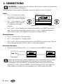
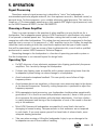
4. CONNECTIONS
WARNING: To prevent the risk of electric shock, do not connect the loudspeaker
with the amplifier switched on.
The loudspeaker has two identical Speakon connectors, which are wired as follows:
Inputs:
• Pin 1+ is the positive (+) input,
and connects to the positive (+)
output of your power amplifier.
VRM12 enclosure
+
Pin
+
+
xover
Pin
1+
12+
2-
• Pin 1– is the negative (–) input,
and connects to the negative
(–) output of your power
amplifier.
1+
12+
2-
Speakon
Speakon
• Pin 1+ and 1– of one Speakon are connected internally to the VRM12 crossover’s
input. They are also connected internally to Pin 1+ and 1– of the other Speakon,
which can be used to send speaker-level power to another VRM12.
Through Outputs:
• Pin 2+ is the positive (+) through output.
• Pin 2– is the negative (–) through output.
• Pin 2+ and 2– are not connected internally to the VRM12 crossover’s input. They are
only connected internally to Pin 2+ and 2– of the other Speakon.
Connection Examples:
• Using the second Speakon (Pin 1+,1-) to connect a second VRM12 in parallel.
VRM12 enclosure
2-conductor cable
+
Amp A+
Pin
1+
12+
2-
Speakon
xover
VRM12 enclosure
+
+
+
Pin
Pin
Speakon
Speakon
1+
12+
2-
1+
12+
2-
xover
+
+
Pin
1+
12+
2-
Speakon
Make sure that the total average impedance of your loudspeakers does not drop
below the recommended minimum load impedance of your power amplifier.
For example, when two VRM12s are wired as shown above, the total average
impedance is 4 ohm. For three VRM12s, the total average is 2.67 ohm. Make sure
your amplifier can handle this load impedance, or it may become overloaded.
6 – VRM12