1
!"#$%&
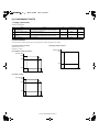
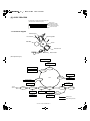
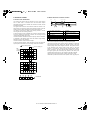
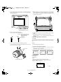
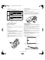
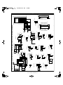
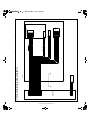
4. Heater lamp control circuit
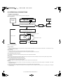
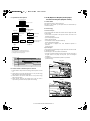
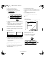
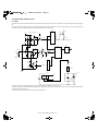
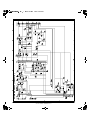
A. Outline
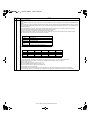
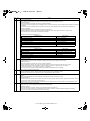
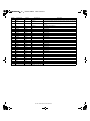
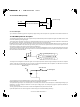
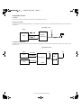
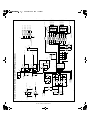
The heater lamp control circuit detects the heat roller surface temperature and converts in into a voltage level, which is inputted to the CPU analog input
pin.
The CPU converts the analog voltage into a digital signal level and compares it with the set value of the simulation to turn on/off the heater lamp
according to the level, maintaining the heat roller surface temperature at a constant level.
5V
1
Driver
IC109
A5V
Q204
5V
THERMISTER SENSE CIRCUIT
DTA143XKA
2
12V
R214
1KF
R218
1MF
R217
7.5KJ
+
2 -
HL
D109
8
3
D108
R220
1.2KJ
IC201A
NJM2903
HLR249
120J1/4W
FTH (4-D2)
1
HLOUT(6-A4)
1SS133
4
MA700
R215
10KF
R216
4.7KJ
C257
0.1u
Driver
CPU
12V
IC103
IC108
A5V
PR
PR-
1
D205
DA204K
3
+
2 -
1
R312
R273
300J
100J
ANo
4
C382
22000p
D206
DA204K
C340
0.1u
2
Heat
roller
1
RTH-IN
(6-C1)
8
Thermistor
IC209A
LM358
A5V
R221
620F
2
C389
0.1u
AN-GND
AN-GND
5V
12V
IC201B
NJM2903
IC202
R244
10KJ
Thermostat
8
5
+
6 -
4
R223
10KF
7
THOPEN (2-E3)
C303
22000p
Heater lamp
AN-GND
HLOUT
Selector
RY1
+24V
TRC1
PC2
AC
PR-
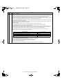
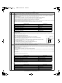
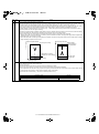
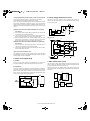
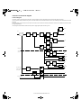
The lower the heat roller surface temperature is, the greater the thermistor resistance is, and vise versa.
Therefore, the lower the heat roller surface temperature is, the higher the thermistor terminal voltage is, and vise versa. The thermistor terminal voltage
is inputted to the CPU analog port.
The CPU controls ON/OFF of the heater lamp by this input voltage level.
AL-1551 ELECTRICAL SECTION 12-11