1
CCD Programming Guide
Please Read
Note:
The Wasp CCD Scanner is ready to scan the most popular
bar codes out of the box. This manual should only be
used to make changes in the configuration of the
scanner for specific applications. This scanner does not
require software or drivers to operate. The scanner enters
data as keyboard data. Please review this manual before
scanning any of the programming bar codes in this manual.
TTech Tip
If you are unsure of the scanner configuration or have
scanned the incorrect codes, please scan the default
bar code on page 6. This will reset the scanner to its
factory settings.
© Copyright Wasp Technologies
All rights reser ved.
Rev H.
No part of this publication may be reproduced or transmitted in any form
or by any means without the written permission of Wasp Bar Code
Technologies. The information contained in this document is subject to
change without notice.
Wasp is a trademark of Wasp Technologies. All other trademarks or registered trademarks are the
property of their respective owners.
Table of Contents
Chapter 1.
Chapter 2.
Chapter 3.
Chapter 4.
Chapter 5.
Appendix A.
Appendix B.
Appendix C.
Introduction.............................................................................. 1
Installation................................................................................2
Quick Start ..............................................................................3
Bar Code Symbologies............................................................4
CCD Setup & Configuration ..............................................5-30
1.
Set Default ..............................................................6
2.
Terminator ..............................................................7
3.
Preamble/Postamble ..............................................8
4.
CCD Hardware ..................................................9-10
5.
Keyboard Type ......................................................11
6.
Keyboard Setting ..................................................12
7.
CCD Scanning Control....................................13-15
8.
Enable Bar Code Symbologies ............................16
9.
Code Identification................................................17
10. Code 39 ................................................................18
11. Code 128..............................................................19
12. MSI Plessey ..........................................................20
13. Interleaved 2 of 5..................................................21
14. Codabar................................................................22
15. UPC-A ..................................................................23
16. UPC-E ..................................................................24
17. EAN/JAN-13..........................................................25
18. EAN/JAN-8............................................................26
19. Language..............................................................27
20. Interface Options ..................................................28
21. Serial (COM) Port Setting................................29-30
Bar Code Test Symbols....................................................31-33
Lookup Table for Bar Code Lengths ................................34-35
Preamble/Postamble Addition Table ................................36-37
Product Support ..............................................................................................38
Warranty
..............................................................................................38
Chapter 1
Introduction
Bar coding is the most common Automated Data Collection (ADC) technology
providing timely, error-free information that can be used to increase productivity,
accuracy, and efficiency in the workplace. Virtually every type of industry is
using bar codes to replace keyboard data entry. Studies have shown that a
proficient data entry operator will make one error for every 300 characters that
are manually entered. The error rate using bar codes is almost negligible and
can be error-free using bar code symbologies with the check digit enabled.
The Wasp Charged Coupled Device (CCD) technology is a technique whereby a
bar code is photographed, digitized, and electronically sampled by built-in
photodetectors. The detectors process the measurement of every bar and
space using the number of adjacent photodetectors which contrast a black mark
and a white space. The Wasp CCD is extremely rugged since it has no moving
parts. The Wasp CCD reader supports PC AT/XT and PS/2 keyboard interfaces
and easily wedges between the computer and keyboard. Bar code data is
passed directly into the keyboard buffer as if it had been typed in by hand by a
data entry operator.
Of all the hand held, bar code scanning devices on the market, the CCD reader
is the easiest to use and most cost effective for the typical business user. The
Wasp CCD scanner is a one touch scanner allowing the user to come in direct
contact with the bar code. It also supports a depth of reading of up to 1.4 inches
to successfully decode a bar code symbology. Bar codes up to 3.15 inches in
length can be scanned. To activate the scanner, the user simply covers the bar
code with head of the scanner and pulls the trigger. The Wasp CCD supports a
scan rate of 50 scans per second.
1
Chapter 2
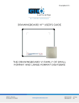
Installation
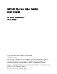
Keyboard Wedge Cable
Scan Feedback Indicator
Keyboard
Y-Cable
Trigger
Scanning Aperture
Din-6M
Din-5M
Din-6F
Din-5F
(PC Only)
Side View
Scanning
Aperture
Cable
Removal Hole
(PC Only)
(Push paper clip into hole and
pull cable simultaneously to
remove cable)
Trigger
Buzzer
Bottom View
1.
2.
3.
4.
Turn off your computer.
Plug the keyboard wedge cable into the handle of the CCD reader.
Unplug your PC keyboard cable and plug the male end (Din 5) of the Wasp
CCD scanner directly into your PC keyboard port. Plug your keyboard
cable into the other end (female Din 5) of the the Wasp CCD scanner. If
your keyboard and PC support a Din 6 connection, use the enclosed Din 5
to Din 6 converter cables.
Turn your computer on.
Note: Make sure scanner is not plugged into the mouse port. Scanner will
not function properly if plugged into mouse port.
2
Chapter 3
Quick Start
Your Wasp CCD Scanner is ready to go. The default settings of the Wasp CCD
Scanner have been pre-programmed for the most common bar code
configurations. Use the "CCD Setup & Configuration" sections only to customize
the Wasp CCD settings. Please review the 'Enable Bar Code Symbologies'
configuration on page 16 to see the list of bar code symbologies which are
enabled by default.
Tip: Use the pre-printed "Bar Code Test Symbols" in Appendix A on page 31
as a test chart to begin practicing scanning.
3
Chapter 4
Bar Code Symbologies
Bar codes are symbols consisting of a series of bars and spaces which can be
applied to packages, cartons, bottles, and other commercial products. The bars
and spaces in each symbol are grouped in such a way to represent a specific
ASCII character or function. The interpretation of these groups is based on a
particular set of rules called symbologies. Various symbologies have been
developed for particular applications. Some examples are shipping and
receiving, manufacturing, retail, healthcare, transportation, document
processing, tracking, and libraries.
The resolution of a bar code is dependent on the narrowest element of a bar
code (X dimension), and can vary from high density (nominally less than 0.009
in./0.23 mm), medium density (between 0.009 in./0.23 mm and 0.020 in./0.50
mm), and low density (greater than 0.020 in./0.50 mm). Medium and low
densities are the most common since these are the easiest to read (scan) with
nearly all scanning devices. The Wasp CCD scanner can read bar codes with
X-dimensions as low as 5 mils (0.005 in./0.127 mm).
The Wasp CCD scanner can read the most popular bar code symbologies
including Code 39, Code 128, Interleaved 2 of 5, UPC-A, UPC-E, EAN/JAN-8,
EAN/JAN-13, Codabar, MSI Plessey, and Code 93.
Please see test chart on page 31.
4
Chapter 5
CCD Setup & Configuration
In order to configure the Wasp CCD scanner, you must familiarize yourself with
the setup procedures on the following pages. The default settings of the Wasp
CCD scanner are identified on each page and clearly marked with an asterisk
(*). The default settings have been preprogrammed for the most common
bar code configurations. Use the CCD Setup & Configuration only to
customize the Wasp CCD settings. If you need to configure the Wasp CCD
reader, the default settings will be overwritten. All the programmed settings are
stored permanently in non-volatile memory. Therefore, your configuration will be
maintained even if keyboard power to the Wasp CCD scanner is removed by
turning off your PC.
In order to configure the Wasp CCD, three basic steps need to be followed for
each programmed setting:
(1) Scan the 'Begin' bar code with the Wasp CCD reader to select your
configuration
(2) Scan the appropriate setting(s) to customize the CCD configuration
(3) Scan the corresponding 'End' bar code with the Wasp CCD reader
Three or more audible beeps will be heard after each step is completed.
Note: If you are unsure whether or not you have programmed the scanner
properly, return to page 6 and return the scanner back to the default settings.
Then begin the configuration process again.
5
CCD Setup & Configuration
—Set Default Configuration
The 'Set Default' configuration restores the factory default settings.
Tip: Use this option to restore the factory default settings if you are unsure of
your CCD’s configuration. The 'Set Default' configuration is very useful when
you need to reprogram your Wasp CCD reader after the defaults have been
changed. By setting the default configuration, the user knows precisely the
configuration for each programmed setting.
Begin
Default
6
CCD Setup & Configuration
—Terminator Configuration
The 'Terminator' configuration is used to specify the end-of-text message. The
terminator character is the last character sent to the keyboard buffer and comes
after the Postamble characters if they are configured. It is primarily used to
denote the end of the bar code value.
Tip: If you need another character that is not listed as one of the terminator
characters, you can use the 'Postamble' Configuration to add a suffix character or
string.
Begin
None
Carriage Return
*
Space
Escape
End
*Default
7
CCD Setup & Configuration
—Preamble/Postamble Configuration
The 'Preamble/Postamble' configuration is used to add a prefix or suffix set of
characters to the bar code value. Up to 7 characters may be added for each
option separately. Preamble and postamble characters can function concurrently,
but need to be configured separately.
To add preamble or postamble characters, follow the steps below:
(1) Scan the 'Begin' bar code on this page
(2) Scan the 'Preamble' or 'Postamble' option
(3) Use Appendix C on page 36 to locate the characters you want to add as
preamble or postamble characters. Find the two character 'Code' associated
with the character you want to add. Scan the two characters on page 35.
Make sure that you scan the two bar codes associated with each letter before
preceding to the next character. This step can be repeated up to six more
times - seven total. For example, to add the letter "A," scan the "4," and then
the "1" on page 35. The letter "A" will always appear in your data as a prefix
or suffix to the bar code value.
(4) Scan the 'Set' option on page 35.
(5) Scan the 'End' bar code on this page.
Begin
Preamble
Note: Please use Appendix C regarding the prefix string. You may add up to 7
characters as a Preamble.
Postamble
Note: Please refer to Appendix C regarding the suffix string. You may add up to
7 characters as a Postamble.
End
8
CCD Setup & Configuration
—CCD Hardware Configuration:
The 'CCD Hardware' configuration supports the general control options for the
CCD reader. These options include the buzzer volume, buzzer duration, and
intercharacter delay. The intercharacter delay should be changed only if the
transfer rate cannot be maintained between the CCD reader and the keyboard
buffer of the computer.
Note: The default for the intercharacter delay is set to 'Medium' and is the most
common configuration; however, your PC may be different. When you scan a
bar code, if some characters are missing, use the 'Fast' option to speed up the
transfer rate. If some stray or scrambled characters appear at your cursor, use
the 'Slow' option to slow down the transfer rate.
Begin
* Highest
High
Buzzer Volume
Medium
Low
Lowest
cont. on next page
End
9
*Default
CCD Setup & Configuration
—CCD Hardware Configuration (cont.):
Begin
0.3 Seconds
Buzzer Duration
* 0.1 Seconds
1 Second
* Medium
Fastest
Intercharacter Delay
Fast
Slowest
Slow
End
10
*Default
CCD Setup & Configuration
—Keyboard Type Configuration
The 'Keyboard Type' configuration is used to program the reader for the type of
computer it is attached to. This configuration is only used when the 'Interface
Options' configuration is set to 'Keyboard'.
Begin
*PC AT, PS/2 50 60 70 80
PC XT
Keyboard Type
PS/2 25 30
Macintosh
End
*Default
11
CCD Setup & Configuration
—Keyboard Setting Configuration
The 'Keyboard Setting' configuration provides specific options on how to pass
your data to the keyboard buffer. 'Lower Case' is the default and toggles upper
to lower case letters. For example, "A" is modified to "a". 'Upper Case' toggles
lower to upper case letters. Either 'Lower Case' or 'Upper Case' can be
enabled, but not both simultaneously. When 'Alphanumeric' is enabled all
characters are passed unmodified. When 'Number Lock' is enabled, numbers
that are in your bar coded values will be passed to the keyboard buffer if the
"Num Lock" key is enabled on your keyboard. If the "Num Lock" key is disabled,
numbers that are in your bar coded values will not be passed to the keyboard
buffer of your computer.
Begin
*Lower Case
Upper/Lower Case
Alphanumeric
Upper Case
*Alphanumeric
Alphanumeric/Number Lock
Number Lock
End
*Default
12
CCD Setup & Configuration
—CCD Scanning Control Configuration
The 'CCD Scanning Control' configuration allows the user to customize how the
trigger is to operate, the length of time in which the LEDs (i.e. the CCD
photodetectors) are on, and activates auto scanning. The Wasp CCD has seven
(7) options to control this configuration. Only one option can be enabled at a time.
Note: When the LEDs are visible, the CCD scanner can read the bar code
symbologies that are enabled. See 'Enable Bar Code Symbologies' for further
information.
Begin
Trigger Pressed
When this option is selected, the LEDs become
visible when the trigger is pressed, and the
LEDs will immediately go off when the trigger is
released.
Trigger pressed
* Trigger with 3 Sec. Delay
This is the default option for the Wasp CCD
scanner. When this option is selected, the
LEDs become visible when the trigger is
pressed, and will remain on for three (3)
seconds or until a bar code is scanned.
* Trigger with Delay
Tip: The delay option is a useful feature if you are scanning multiple bar codes
back-to-back. 'Trigger with 3 Sec.Delay' is the default because it is the optimal
configuration when you are setting up the Wasp CCD reader. Three bar codes
are generally scanned for each step: 'Begin', an option, and 'End'. When this
option is enabled, the trigger is typically only pressed one time to scan all three
steps.
cont. on next page
End
13
*Default
CCD Setup & Configuration
—CCD Scanning Control Configuration (cont.)
Begin
On/Off Trigger with 3 Second Delay
When this option is selected, the LEDs become
visible when the trigger is pressed, and will
remain on for 3 seconds. The LEDs will turn off
automatically after 3 seconds whether a bar
code is successfully scanned or not or if the
trigger is pressed again.
On/Off Trigger—
3 Second Delay
On/Off Trigger with 30 Second Delay
When this option is selected, the LEDs
become visible when the trigger is pressed,
and will remain on for 30 seconds. The LEDs
will turn off automatically after 30 seconds
whether a bar code is successfully scanned or
not or if the trigger is pressed again.
On/Off Trigger—
30 Second Delay
On/Off Trigger with 120 Second Delay
When this option is selected, the LEDs
become visible when the trigger is pressed,
and will remain on for 120 seconds. The LEDs
will turn off automatically after 120 seconds
whether a bar code is successfully scanned or
not or if the trigger is pressed again.
On/Off Trigger—
120 Second Delay
cont. on next page
End
14
*Default
CCD Setup & Configuration
—CCD Scanning Control Configuration (cont.)
Begin
Auto Scan
When this option is enabled, the LEDs are
always visible and the CCD reader will operate
continuously without the need of using the
trigger. In this mode, the CCD reader will not
read identical bar code values back-to-back (i.e.
one right after another).
Auto Scan
Continuous Scan
When this option is enabled, the LEDs are
always visible and the CCD reader will operate
continuously without the need of using the
trigger. This mode is very similar to the 'Auto
Scan' mode with the exception that the CCD
reader will read identical bar code values backto-back.
Continuous Scan
End
*Default
15
CCD Setup & Configuration
—Enable Bar Code Symbologies Configuration
The 'Enable Bar Code Symbologies' configuration is used to enable or disable
the various codes that the reader is able to decode. Multiple bar code
symbologies can be enabled simultaneously.
Begin
ON
Code 39
OFF
*
Interleaved 2 of 5
*
Codabar
*
UPC-A
EAN/JAN-13
*
EAN-8
*
UPC-E
*
EAN/UPC Add-on 2/5
Code 128
*
*
MSI/Plessey
*
Code 93
*
End
16
*Default
CCD Setup & Configuration
—Code Identification Configuration
The 'Code Identification' configuration provides the option to precede each bar
code symbology read with a character that identifies the type of symbology
read. Only one code identifier is allowed for each specific type of bar code.
These can be found in Appendix C on page 36. For example, to set the code
identifier for Code 39 to be "A":
(1) Scan the 'Begin' bar code on this page
(2) Scan the 'Code 39' option
(3) Turn to page 35 and scan the two bar codes associated with letter "A"
(4) Scan the 'Set' option in Appendix C.
(5) Scan the 'End' bar code on this page.
In this example, each and every time a Code 39 bar code symbology is
scanned, the letter "A" will precede the bar code value.
Begin
Code 39
Interleaved 2 of 5
Codabar
EAN-13/UPC-A
EAN-8
UPC-E
MSI/Plessey
Code 128
End
17
*Default
CCD Setup & Configuration
—Code 39 Configuration
Code 39 is variable length and is the most frequently used symbology in industrial
bar code systems today and is extensively used within the Department of Defense
(DOD). The principal feature is to encode messages using the full alphanumeric
character set. The Code 39 bar code uses four special characters "$", "/", "+". "%"
which can be paired with alphanumeric characters to extend to the full ASCII
character set. Standard Code 39 contains only 43 characters (0-9, A-Z, $, /, %, +,
-, ., SPACE) and can be extended to a 128 character symbology (full ASCII) by
combining one of the special characters ($, /, %, +) with a letter (A-Z) to form the
characters that are not present in the standard Code 39 symbology.
Begin
Off
On/Off
On
*
Standard Type
*
Type
Full ASCII
Transmit Start/Stop
Character
No
*
Yes
No
*
Verify Checksum
Yes
Transmit Check
Character
No
Yes
*
End
18
*Default
CCD Setup & Configuration
—Code 128 Configuration
Code 128 is the most easily read bar code with the highest message integrity due
to several separate message check routines. Of all the common linear
symbologies, Code 128 is the most flexible. It supports both alpha and numeric
characters, has the highest number of characters per inch, and is variable length.
Code 128 is usually the best choice when implementing a new symbology. United
Parcel Service (UPS) extensively uses this symbology.
Begin
Off
On/Off
On
*
End
*Default
19
CCD Setup & Configuration
—MSI Plessey Configuration
MSI Plessey is a variable length numeric symbology primarily used in marking
retail shelves. Each character consists of four bars with intervening spaces for
each encoded digit, one or two symbol check digits, and a reverse start code.
Begin
Off
*
On/Off
On
End
*Default
20
CCD Setup & Configuration
—Interleaved 2 of 5 Configuration
Interleaved 2 of 5 is a variable length, numeric bar code with an even number of
digits. It is typically used in industrial and master carton labeling and also in the
automotive industry. The symbology uses bars to represent the first character and
the interleaved (white) spaces to represent the second character.
The 'Interleaved 2 of 5' configuration provides the option to define up to three (3)
fixed bar code lengths (i.e. number of characters). For example, to define the
length of the bar code symbology, you must refer to Appendix B on page 34 and
follow the steps below:
(1) Scan the 'Begin' bar code on this page
(2) Scan the 'Define Length' option
(3) Use the lookup table (Appendix B) to find the value (0 - 255) and to define the bar
code length. If, for example, the length is to be "10", the lookup value is "0A". Scan
"0" first and then scan "A". This step can be repeated one to three times.
(4) Scan the 'Set' option in Appendix B.
(5) Scan 'End'.
Begin
Off
*
On/Off
On
No
*
Transmit Check Digit
Yes
No
*
Verify Check Digit
Yes
Define Length
End
21
*Default
CCD Setup & Configuration
—Codabar Configuration
Codabar is a variable length symbology capable of encoding up to 16 characters.
Codabar can encode six special alphanumeric characters, capital letters A
through D, T, N, *, E, and all numeric digits. Codabar is one of the oldest bar code
symbologies and is still used in some library applications. Codabar symbology is
not recommended for any new applications.
Begin
Off
On/Off
On
*
No
*
Transmit Start/End
Yes
ABCD/ABCD
ABCD/TN*E
Start/End Transmit Type
abcd/abcd
*
abcd/tn*e
End
22
*Default
CCD Setup & Configuration
—UPC-A Configuration
UPC-A (Universal Product Code-A) is a fixed length symbology and is the most
common bar code used for retail product labeling. It is seen in most grocery stores
across the United States. The symbology encodes a 12-digit, numeric-only
number. The first six digits are assigned by the Uniform Code Council (UCC) in
Dayton, Ohio. The next five digits are assigned by the manufacturer, and the final
digit is a modulo 10 check digit. The nominal height for the UPC-A bar code is
one inch. The reduced size is 80% of the nominal size.
Begin
Off
On/Off
On
*
No
*
Truncate Leading Digit
Yes
No
*
Truncate Leading 0
Yes
No
Transmit Check Digit
Yes
*
End
23
*Default
CCD Setup & Configuration
—UPC-E Configuration
UPC-E (Universal Product Code-E) is also a fixed length symbology and is a
compressed six digit code used for marking small packages including magazines
and paperback books. UPC-E symbols are UPC-A symbols that have been zero
suppressed (i.e. consecutive zeros are not included in the symbol). The printed
value of the UPC-E code is a twelve digit code. The nominal height for the UPC-E
bar code is one inch. The reduced size is 80% of the nominal size.
Begin
Off
On/Off
On
*
No
*
Truncate Leading Digit
Yes
No
Transmit Check Digit
Yes
*
End
24
*Default
CCD Setup & Configuration
—EAN/JAN-13 Configuration
EAN/JAN-13 (European Article Number/Japanese Article Number) is a fixed
length symbology and is similar to the UPC-A symbology, but encodes a 13th
digit. The nominal height for the EAN/JAN-13 bar code is one inch. The reduced
size is 80% of the nominal size.
Begin
Off
On/Off
On
*
No
*
Truncate Leading Digit
Yes
No
*
Truncate Leading 0
Yes
No
Transmit Check Digit
Yes
*
End
25
*Default
CCD Setup & Configuration
—EAN/JAN-8 Configuration
The EAN/JAN-8 is a fixed length symbology and is similar to the UPC-E code, but
includes two more digits for the country code. The nominal height for the
EAN/JAN-8 bar code is one inch. The reduced size is 80% of the nominal size.
Begin
Off
On/Off
On
*
No
*
Truncate Leading Digit
Yes
No
Transmit Check Digit
Yes
*
End
26
*Default
CCD Setup & Configuration
—Language Configuration
The 'Language' configuration is used to setup the appropriate keyboard translation
for a particular country. Only one language can be selected at a time.
Begin
US
*
French
German
Spanish
Swiss
UK
End
27
*Default
CCD Setup & Configuration
—Interface Options:
The Wasp CCD 'Interface Options' configuration supports a keyboard wedge
and RS232 (serial) interface. Only one interface option can be enabled at a
time. Note: The RS232 interface is a special option. Please see the 'Product
Support' section to contact us for this option.
Begin
*Keyboard
RS-232
End
28
*Default
CCD Setup & Configuration
—Serial (COM) Port Setting Configuration
Note: The RS232 interface is a special option. Please see the 'Product
Support' section to contact us for this option.
The WASP CCD supports an RS232 serial configuration for baud rate, data bits,
parity, and hand shaking. The 'Serial (COM) Port Setting' configuration must
correspond to your manufacturer's requirement for serial communication.
Please consult your manufacturer's documentation for your serial (COM) card.
Begin
Reserved
150
300
600
Baud Rate
1200
2400
4800
*9600
19200
cont. on next page
End
29
*Default
CCD Setup & Configuration
—Serial (COM) Port Setting Configuration (cont.)
Begin
7 Bits
Data Bits
* 8 Bits
* None
Parity
Even
Odd
* None
Flow Control
Xon/Xoff
Hardware (RTS/CTS)
End
30
*Default
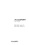
CCD Setup & Configuration
—Bar Code Test Symbols—Appendix A
Note: Make sure that the appropriate bar code symbology is configured
properly and enabled before trying to scan. Use the 'Enable Bar Code
Symbologies' configuration on page 16 to enable specific symbologies.
Code 39
(Default: Enabled)
Interleaved 2 of 5
(Default: Disabled)
Codabar
(Default: Enabled)
Code 128
(Default: Enabled)
MSI/Plessey
(Default: Disabled)
31
CCD Setup & Configuration
—Bar Code Test Symbols—Appendix A (cont.)
UPC-A
(Default: Enabled)
UPC-A
5 digit supplement
(Default: Disabled)
UPC-A
2 digit supplement
(Default: Disabled)
UPC-E
(Default: Enabled)
UPC-E
5 digit supplement
(Default: Disabled)
UPC-E
2 digit supplement
(Default: Disabled)
32
CCD Setup & Configuration
—Bar Code Test Symbols—Appendix A (cont.)
EAN/JAN 13
(Default: Enabled)
EAN/JAN 13
5 digit supplement
(Default: Disabled)
EAN/JAN 13
2 digit supplement
(Default: Disabled)
EAN/JAN 8
(Default: Enabled)
EAN/JAN 8
5 digit supplement
(Default: Disabled)
EAN/JAN 8
2 digit supplement
(Default: Disabled)
33
CCD Setup & Configuration
—Lookup Table for Bar Code Lengths—Appendix B
Use this Lookup Table to specify the lengths (i.e. the number of bar code
characters) when scanning. Note: Please refer to the configuration topic of
your specific bar code symbology to see if this option is relevant and how many
values can be entered. Use the lookup values on page 35 to enter the values
between 0 and 255.The 'Set' bar code option must be scanned after the final
value has been read in order to successfully set the bar code length.
34
cont. on next page
CCD Setup & Configuration
—Lookup Table —Appendix B (cont.)
0
8
1
9
2
A
3
B
4
C
5
D
6
E
7
F
SET
35
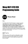
CCD Setup & Configuration
—Preamble/Postamble Addition Table—Appendix C
Use this table to add preamble and postamble characters to your bar code
value. Make sure that you scan the two bar codes associated with each ASCII
character on page 35 before preceding to the next character. Up to seven ASCII
characters can be added. Scan the 'Set' option when you are finished.
For example, to add a Right Brace and a Tab as a postamble:
• Scan 'Begin' and 'Preamble' on page 8
• Scan '7' and 'D' on page 35 for the right brace
• Scan '8' and '9' on page 35 for the Tab
• Scan 'Set' on page 35 to terminate the addition of preamble characters
• Scan 'End' on page 8 to complete the preamble addition
Preamble/Postamble Addition Table
Code ASCII
Code ASCII
Code ASCII
Code ASCII
00
01
02
03
04
05
06
07
08
09
0A
0B
0C
0D
0E
0F
10
11
12
13
14
NULL
SOH
STX
ETX
EOT
ENQ
ACK
BEL
BS
HT
LF
VT
FF
CR
SO
SI
DLE
DC1
DC2
DC3
DC4
15
16
17
18
19
1A
1B
1C
1D
1E
1F
20
21
22
23
24
25
26
27
28
29
NAK
SYN
ETB
CAN
EM
SUB
ESC
FS
GS
RS
US
Space
!
"
#
$
%
&
'
(
)
2A
2B
2C
2D
2E
2F
30
31
32
33
34
35
36
37
38
39
3A
3B
3C
3D
3E
36
*
+
,
.
/
0
1
2
3
4
5
6
7
8
9
:
;
<
=
>
3F
40
41
42
43
44
45
46
47
48
49
4A
4B
4C
4D
4E
4F
50
51
52
53
cont. on next page
?
@
A
B
C
D
E
F
G
H
I
J
K
L
M
N
O
P
Q
R
S
CCD Setup & Configuration
—Preamble/Postamble Addition—Appendix C (cont.)
Preamble/Postamble Addition Table (cont.)
Code ASCII
Code ASCII
Code ASCII
Code ASCII
54
55
56
57
58
59
5A
5B
5C
5D
5E
5F
60
61
62
63
64
65
66
T
U
V
W
X
Y
Z
[
\
]
^
_
`
a
b
c
d
e
f
67
68
69
6A
6B
6C
6D
6E
6F
70
71
72
73
74
75
76
77
78
79
g
h
i
j
k
l
m
n
o
p
q
r
s
t
u
v
w
x
y
7A
7B
7C
7D
7E
7F
80
81
82
83
84
85
86
87
88
89
8A
8B
8C
37
z
{
|
}
~
Home
End
Page Up
Page Down
Insert
Delete
Num Lock
Break
Tab
Enter
Left Arrow
Right Arrow
8D Enter (kpd)
8E Up Arrow
8F Down Arrow
90
F1
91
F2
93
F4
94
F5
95
F6
96
F7
97
F8
98
F9
99
F10
9A
F11
9B
ESC
9C
F12
9D
Shift
9E
Ctrl
9F
Alt
Product Support
If you experience any problems with Wasp CCD that you are unable to resolve,
call for technical assistance at (214) 547-4100, Monday through Friday,
8:00 AM - 5:00 PM U.S. Central Standard Time. Also, please consult our FAQ
(Frequently Asked Questions) section on our web site at
www.waspbarcode.com
You may also contact us in writing at:
Wasp Technologies
1400 10th Street
Plano, TX 75074
(214) 547-4100
(214) 547-4101 Fax
Warranty Information
Wasp Technologies products are warranted against defects in workmanship and
materials for a period of one year from the date of shipment, provided that the
product remains unmodified and is operated under normal and proper
conditions.
This warranty is limited to repair or replacement at Wasp Technologies option,
with reasonable promptness after being notified. These provisions do not
extend the original warranty term for any product which has been repaired or
replaced by Wasp Technologies.
This warranty applies to the original owner and does not extend to any product
which has been subject to misuse, neglect, accidental damage, unauthorized
repair, or tampering.
No other express warranty is given.The replacement or repair of a product is
your exclusive remedy. Any other implied warranty of merchantability or fitness
is limited to the duration of this written warranty. Some states, provinces, and
countries do not allow limitations on the duration of an implied warranty, so the
above limitation may not apply to you.
In no event shall Wasp Technologies be liable for consequential damages. Some
states, provinces, and countries do not allow the exclusion or limitation of incidental
or consequential damages, so the above limitations may not apply to you.
38