1
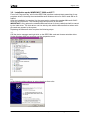
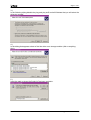
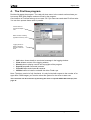
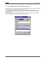
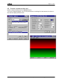
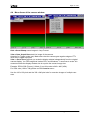
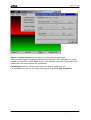
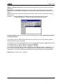
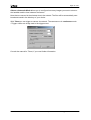
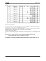
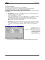
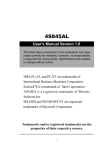
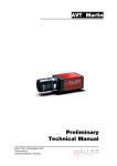
Page 1 of 20
Operating Instructions
FireView
intek hard- & softwaretechnik
www.intek-darmstadt.de
adelungstr. 34
64283 darmstadt
distributed by:
AVT
Allied Vision Technologies
Taschenweg 2a
07646 Stadtroda
www.alliedvisiontec.com
Documentation FireView – Distributed by Allied Vision Technologies
Page 2 of 20
Contents
CONTENTS ................................................................................................................ 2
1.
INTRODUCTION ................................................................................................. 3
2.
SYSTEM REQUIREMENTS ................................................................................ 4
3.
INSTALLING THE SOFTWARE.......................................................................... 5
3.1
Installation of the driver under WINDOWS ™ NT4............................................... 5
3.2.
Installation under WINDOWS™ 2000 and XP™..................................................... 6
4.
THE FIREVIEW PROGRAM................................................................................ 9
4.1
Connecting FireView with an IEEE1394 adapter card .......................................... 10
4.2
Connect a camera to the card.................................................................................... 11
4.4
Menu items of the camera window ........................................................................... 13
4.5
Tables of formats and Modes: (Source: DCAM Spec V1.3)................................... 17
4.6
Bandwidths and limits ............................................................................................... 19
4.7
Multiple IEEE1394 adapter cards in one PC .......................................................... 19
4.8
Error messages ........................................................................................................... 20
Documentation FireView – Distributed by Allied Vision Technologies
Page 3 of 20
1. Introduction
FireView is a demo program from the company intek (www.intek-darmstadt.de) and is designed to operate IEEE1394 DCAM-compatible cameras.
It demonstrates the functionality and performance of the FIREPSTACK OHCI API (Application Programming Interface) which is offered at very low cost together with IEEE1394 cameras from your local distributor.
•
•
•
•
•
FIRESTACK works with almost every IEE1394 Adapter, no matter whether OHCI or
PCILynx, on board or PCI-Type or PCMCIA
FIRESTACK OHCI can operate and display multiple cameras in parallel,
FIRESTACK OHCI is highly efficient and stable,
FIRESTACK OHCI is designed by programmers with a long background in industrial imaging and solid software know how;
FIRESTACK OHCI is the ideal solution for your IEEE1394 camera application.
Remarks:
Please be aware that some dialogs and menues might have been changed slightly with
newer versions of FireView. The basic functionality still will be the same.
Documentation FireView – Distributed by Allied Vision Technologies
Page 4 of 20
2. System requirements
•
•
•
•
•
•
WINDOWS™ NT4 SP5 or WINDOWS™2000 or XP
PCI-Lynx compatible IEEE1394 Adapter- Card (SONY DFWA-400, ZENKUMAN
PFW-41, IOI 1394TT)
OHCI ™ compatible Adapter cards (IOI 1394TTO…)
PCMCIA style OHCI Cards (IOI CB1394D)
Built in IEEE1394 ports
IEEE1394 cameras following DCAM- Standard e. g..
·
·
·
·
·
·
·
·
·
·
·
·
·
·
·
·
·
·
·
·
·
SONY XCD-X700
SONY XCD- SX900
SONY DFW-V300
SONY DFW-V500
SONY DFW-VL500
SONY DFW-X700
SONY DFW-SX900
TELI IEEE1394 cameras
All IEEE1394 Webcams with TI TSB15LV01 Chipset.
Allied Vision Technologies D1
Allied Vision Technologies D2
Allied Vision Technologies Marlin F-033B/C
Allied Vision Technologies Marlin F-046B/C
Allied Vision Technologies Marlin F-080B/C
Allied Vision Technologies Marlin F-131B/C
Allied Vision Technologies Marlin F-145B2/C2
Allied Vision Technologies Dolphin F-145B/C
Allied Vision Technologies Dolphin F-201B/C
Allied Vision Technologies Oscar F-320C
Allied Vision Technologies Oscar F-510C
Allied Vision Technologies Oscar F-810C
Documentation FireView – Distributed by Allied Vision Technologies
Page 5 of 20
3. Installing the software
Copy the program FireView.exe and the two directories for the driver for NT and W2000/XP
into a directory of your choice.
The subsequent installation is dependant on the operating system.
3.1 Installation of the driver under WINDOWS ™ NT4
You must be a logged on as an ADMINISTRATOR in order to install drivers under WINDOWS™.
Start FireView.exe. Press the button Utilities. Then click on Install Driver. The logging
window reports the result of the installation. This procedure is necessary only once. Subsequently the operating system takes care of starting the driver at boot time.
Documentation FireView – Distributed by Allied Vision Technologies
Page 6 of 20
3.2. Installation under WINDOWS™ 2000 and XP™
First of all “Plug and Play” will find the IEEE1394 interface card and starts searching for appropriate drivers. Normally the standard Microsoft Windows driver for OHCI cards will be installed.
After the installation is complete it is the users task to replace the standard Microsoft OHCI
driver by the intek driver. The following steps show how to do this work.
IMPORTANT: Only replace the standard Microsoft driver for those cards that shall be owned
by the intek driver. The intek driver can live side by side with the Microsoft driver when multiple cards are present in the system.
Replacing the Microsoft driver requires the following steps:
1.)
Call the device manager and right click on the IEEE1394 card and choose actualise driver.
Under Windows 2000 you must go over the properties menu.
2.)
In the following dialog choose to select the driver from a list.
Documentation FireView – Distributed by Allied Vision Technologies
Page 7 of 20
3.)
In the following dialog disable the plug and play stuff and tell Windows that you will select the
driver by yourself.
4.)
In the dialog that appears select to find the driver on a storage medium (disk or anything
else).
5.)
Insert the path to where the firedrv.inf has been copied to.
Documentation FireView – Distributed by Allied Vision Technologies
Page 8 of 20
6.)
Select the shown hardware with the name ‘OHIC/PCILYNX-1394-Hostcontroller’.
7.)
Ignore all signature warnings and just continue until you reach the following dialog:
8.)
Typing the finish button ends the installation process.
Documentation FireView – Distributed by Allied Vision Technologies
Page 9 of 20
4. The FireView program
Double click starts the program. The card pull down menu in the control section shows you
how many IEEE1394 adapter cards are found by the program.
One instance of FireView belongs to one card. So if you have two cards start FireView twice.
You can then operate these cards in parallel.
Control section to
choose the adapter
card
Status window, indicating
payload and memory used
Logging window to
display messages
and errors from the
driver
•
•
•
•
•
•
Info button shows details to a selected message in the logging window
Clear deletes content of the logging window
About button to display version and copyrights of the program
Stop All stops all connected cameras.
Close All stops and closes all cameras.
Utilities button to install or uninstall the driver Firedrv.sys.
Note: The demo version is fully functional. It is only limited with respect to the number of images After 5.000 images, you need to reboot the system for the driver to start new.
This restriction can be overcome by licensing the driver to specific IEEE1394 camera(s). See
page 10.
Documentation FireView – Distributed by Allied Vision Technologies
Page 10 of 20
4.1 Connecting FireView with an IEEE1394 adapter card
Choose a card. Assuming that you have already connected cameras to that card you will see
all cameras with their relevant model numbers and identities.
In our case we have connected two VGA- type Color cameras SONY DFW-V500 to card 1.
Up to three cameras of the same or different type can be connected per adapter and operated independently.
Please be aware of certain IEEE1394 bandwidths limits which may apply due to settings of
cameras. Paragraphs 4.6.and 4.7 will tell you more about that.
Documentation FireView – Distributed by Allied Vision Technologies
Page 11 of 20
4.2 Connect a camera to the card
Select a camera and press the Connect button.
Tow more windows appear, one for the preferences or settings for that camera, the other is
the camera display window itself.
Documentation FireView – Distributed by Allied Vision Technologies
Page 12 of 20
In preferences only Camera section is of main interest.
•
•
•
•
•
•
•
•
Video- Format and Video-Mode are related to the DCAM specification settings. (See 4.5
for tables)
X-Offset and Y-Offset are available if the camera supports partial scan and describe the
upper left start-corner of the image
X-Size and Y-Size adjust the size of the partial image.
NOTE: The camera itself may change these values to the ones it supports.
Framerate sets the desired rate in frames/s according to the properties of the camera.
Packetpayload is calculated according to the settings above per IEEE1394 ISO cycle.
Colormode enables various settings according to the abilities of the camera.
Triggermode (int.) is the continuous mode whereas (ext) is the trigger mode. This mode
needs a negative edge of TTL level at the Trigger input connector of the camera. You get
triggered images with a maximum frequency according to the framerate setting. This is
important to know because it allows to adjust bus bandwidth! But: The camera will drop
images if the trigger frequency is higher than the Framerate setting!!
TX- Speed refers to the max bus frequency and should stay at 400. Only users of the
DFW-X300 must switch down for this camera to 200 Mb/s. Other cameras connected to
the card may operate at 400 Mb/s.
Documentation FireView – Distributed by Allied Vision Technologies
Page 13 of 20
4.4 Menu items of the camera window
Disk ->Save Bitmap saves images in .bmp Format.
View-> Start Acquisition starts live image of the camera.
Attention for Trigger mode (ext): Make shure that the camera gets negative edges of TTL
level at the trigger input pins.
View -> Set to xxx x yyy lets you scale the display window independently from the original
camera display. You can image that it takes CPU- and Windows ™ resources to scale. We
recommend that the display window size is equal to the camera image size.
Example: DFW-V500 (Format_0, Mode_3) set View size to 640 x 480 (VGA).
For XGA- size (1024 x 768) please use the Usersize menu.
Use the 160 x 120 pixel and the 320 x 240 pixel size for overview images of multiple cameras.
Documentation FireView – Distributed by Allied Vision Technologies
Page 14 of 20
Others -> Camera Control lets you adjust all relevant camera parameters.
Different camera types have different adjustment possibilities. The card Lense is e.g.only
available with the DFW-VL500; Color only for color cameras in general. Please refer to the
handbooks of the camera about their possibilities.
Edit Settings opens the Preferences windows as already explained in 4.2.
It is accessible only after the live image was stopped by pressing Stop acquisition.
Documentation FireView – Distributed by Allied Vision Technologies
Page 15 of 20
Others -> Direct Control opens the bidirectional asynchronous communication channel of
IEEE1394.
Read (quadlet) and Write (quadlet) read and write camera data according to the DCAM
specification. As this works in parallel to live display you may read and write whenever you
want it.
Make shure that you understand the registers before writing to them, so that the result is a
positive one!
Example: Writing 80000000 in F0F00614 starts ISO image transfer (ISO start),
Writing 00000000 in F0F00614 stops ISO transfer (ISO stop).
License Request reads out a unique camera identifying string. This string will be used for
licensing purposes.
If you want to buy the FIRESTACK OHCI license or API for one or more cameras, please
send this string to your local dealer.
The status line of the image displays the count of all displayed images as seen and the count
of all images which it could probably not display as skipped.
The following formula applies: #Seen + #Skipped = #Trigger
E.G. when you click with the mouse on the title bar of the display-window, WINDOWS ™ is
busy and cannot display images. This indicates that the (real time) driver put the images in
the memory , but the (non real time) view task did not get processing time to display them.
Rate displays a mean rate in frames/s.
Documentation FireView – Distributed by Allied Vision Technologies
Page 16 of 20
Others->Automatic Mode allows you to configure how many images you want to store on
the harddisk and the time between the frames.
Note that one second is the shortest time to be entered. The files will be automatically numbered and saved in the directory of your choice.
With Telnet you can trigger a camera via network. The camera runs in continuous mode.
<Trigger> takes one image next to the trigger event.
Consult the manual for Telnet, if you need further information.
Documentation FireView – Distributed by Allied Vision Technologies
Page 17 of 20
4.5 Tables of formats and Modes: (Source: DCAM Spec V1.3)
Documentation FireView – Distributed by Allied Vision Technologies
Page 18 of 20
How to read the tables:
The tables indicate how many data in pixels or quadlets (4bytes) are going to be transferred
per cycle for certain formats and modes and framerates.
Remember that everything in the IEEE1394 transfer is arranged in cycles, which last 125 µs.
Example: Camera: XCD-SX900, B/W; 7,5 Frames/s 1280 x 960 Pixel:
Please read: Format_2 Mode_2:
One line of 1280 pixels giving 1280 bytes or 320 quadlets (q) needs to be transferred per 125
µs.
Notes: There are modes which are not yet supported by existing camera models!
The cameras tell what formats and modes they support.
For instance, currently there is no SXGA camera which is able to run with 15 frames/s, just
because of lack of appropriate CCD-sensor at the time the camera was designed.
Documentation FireView – Distributed by Allied Vision Technologies
Page 19 of 20
4.6 Bandwidths and limits
As a rule of thumb you can transmit with 400 Mb/s up to 1000q (4000 Bytes) isochronous
data per cycle.
In the example above this means that the bus is 32% loaded with this one camera in this
setting.
Vice versa it means that from the IEEE1394 bandwidth standpoint we should be able to connect up to three cameras with this node (which is true for now-a-days PC’s).
With the color pendant DFW-SX900 (Format_2 Mode_0) we have a load of 64%.
We cannot run two cameras with the max. settings on one node.
But we can if we lower the framerate to 3,75 Hz, because this halves the bus load.
Things are different when we consider the multiplex mode:
Assuming one shot software or hardware trigger, we could connect three cameras per node.
We then trigger the cameras sequentially, just taking care that data transmission does not
overlap.
4.7 Multiple IEEE1394 adapter cards in one PC
FIRESTACK OHCI and FireView is able to handle multiple cards and cameras.
Up to four (three: PCILynx) cameras can be handled per card. Restrictions may apply depending on settings.
When you use multiple cards and cameras be aware that you will reach the bandwidth limit
of the PCI- Bus fairly quickly.
Do not calculate with 132 Mbyte/s (33 MHz x 32 Bit), because this is only a theoretical limit
for the burst mode.
In practise various PC’s showed limits above app. 6000 Byte/cycle data transfer.
FIFO overflows occur and the images start getting corrupted.
This corresponds to a bandwidth of about 50-60 Mbyte/s on the PCI-Bus.
Also interrupt sharing is an important factor which can lower the overall bandwidth available.
So it is very wise to set individual interrupts for the host adapter cards if you run into these
problems.
Also be aware that the PC powers the cameras. You must not exceed its powering capabilities.
Use actively powered repeaters or hubs to power the cameras from outside the PC.
Powering the camera is mandatory when you use the 4-pin connectors of the built in
IEE1394 ports of laptops.
Use actively powered repeaters or hubs to power the cameras from outside the PC.
Documentation FireView – Distributed by Allied Vision Technologies
Page 20 of 20
4.8 Error messages
FIRPACKAGE was developed with focus on industrial vision.
This implies highest robustness and transparent error messaging and handling.
The logging window reports each and every error with date and time.
Info gives you a written description about a selected error message.
In practise (depending on heavy system load) you will probably be confronted with the following messages:
1. GRFOVERFLOW: The Receive FIFO which temporarily stores the camera data on
the adapter card reported an overflow error.
At least one data packet is corrupted.
Please check packetpayload not to exceed 4000 bytes per card or about 6000 bytes
for all cards in order to avoid overload on the IEEE1394-bus or the PCI-bus.
Also check whether other PCI devices are suspect to heavy traffic (e.g. Network
card).
Also Important: Try to avoid interrupt sharing.
2. ISO 0-2 halted: The hardware engine, which collects the data packets was forced to
halt, because there was no free memory in the system. Either the Viewer is too slow
or needs too much processing time for the images or there are not enough frame
buffers.
This setting defines the number of frame stores used by
the driver.
Be aware that e.g. one SXGA
color image corresponds to
3.6 MB of main memory. But
nevertheless you can have as
many frame buffers as you
have memory in the system.
You will find all error messages explained in detail in the FIRESTACK documentation.
Documentation FireView – Distributed by Allied Vision Technologies