1
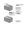
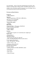
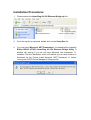
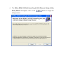
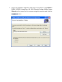
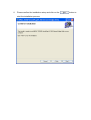
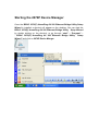
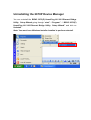
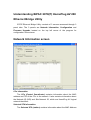
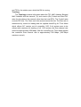
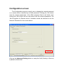
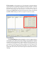
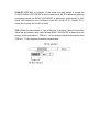
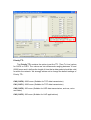
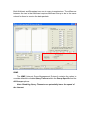
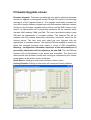
BiPAC 2070(P)
HomePlug AV 200 Ethernet
Bridge
User Manual
Safety Warnings
1.
2.
3.
4.
5.
Do not use the adapter in high humidity or high temperatures.
Do not open or repair the case yourself.
Avoid using this product and all accessories outdoors.
Place the adapter on a stable surface.
Only “HomePlug AV” compliant Powerline Communication (PLC) adapter
for remote access is necessary.
Hardware Overview
The LEDs
*Power LED: Lit when power is ON
*Sync LED: Lit when the network is
formed (CCo and Station function)
*Blinks when packets are transmitted or
received (Station function)
*Ethernet LED: Lit when connected to an
Ethernet device
The Connectors
*Push Button: Power line sync
*Connect your device to
a LAN port, using the
included Ethernet cable
*Connect DC power
cord to your DC
*Reset Button: Hold down
port on device
the reset button for 1~3
(for BiPAC 2070P)
seconds to reset device
to factory default
Connect the AC power
cable to the outlet
Push Button usage
There are 3 types of trigger states for the Push Button.
1.
“Broadcast State”, for a 2070(P) providing information for another 2070(P) to
join its powerline network group (it works even if it is the only one currently in
the group).
2.
“Join State”, for an ungrouped 2070(P) to join an existing powerline network
group.
Press the Push Button on the first 2070(P) device turns it into the “Broadcast State”
and press the Push Button on the second ungrouped 2070(P) device will turn it into
the “Join State”.
3.
“Ungroup State”, press the Push Button for more than 10 seconds, and the
2070(P) will ungroup from its current powerline network group
Scenario 1: 2070(P) Device A wants to form a network group with 2070(P) Device
B.
You can allocate which ever device (A or B) to become the “Broadcast State” and the
“Join State”.
Example:
1.
Hold down the Push Button of 2070(P) Device A for 1~3 seconds to turn it into
the “Broadcast State”.
2.
Hold down the Push button of 2070(P) Device B for 1~3 seconds to turn it into
the “Join State”.
3.
Wait for the Sync LED of both Device A and B to light up and you will have
both devices being in the same network group.
Scenario 2: 2070(P) Device A wants to join an existing network group “BC”.
Device A wants to join a network group “BC” currently consisting of device B and
device C. Any devices within the “BC” group can become the “Broadcast State” and
device A will be the “Join State”.
Example:
1.
Hold down the Push Button of 2070(P) Device B or C (of the “BC” group) for
1~3 seconds to turn it into the “Broadcast State”.
2.
Hold down the Push button of 2070(P) Device A for 1~3 seconds to turn it into
the “Join State”.
3.
Wait for the Sync LED of both Device A and (B or C) to light up and you will
have device A joining the network group “BC”.
Scenario 3: 2070(P) Device A of network group “AD” wants to join an existing
network group “BC”.
For a device which already belongs to an existing group, if it wants to join another
group that device must go into the “Ungroup State” and ungroup itself first.
Example:
1. Hold down the Push Button of 2070(P) Device A for 10 or more seconds to turn
it into the “Ungroup State”. Once it is in the “Ungroup State” it breaks away from the
“AD” network group and becomes an individual device.
2. Hold down the Push Button of 2070(P) Device B or C (of the “BC” group) for
1~3 seconds to turn it into the “Broadcast State”.
3. Hold down the Push button of 2070(P) Device A for 1~3 seconds to turn it into
the “Join State”.
4. Wait for the Sync LED of both Device A and (B or C) to light up and you will
have device A joining the network group “BC”.
Introduction
HomePlug AV Adapter with power supplier
• Physical layer data rate up to 200Mbps over existing Powerline
• Uses powerline technology that takes advantage of the unused bandwidth of
the electrical wiring in the home.
• Ideal for Triple Play applications such as IPTV, VoIP telephony and
high-speed Internet access.
• Support 10/100M (MDI/MDIX) Ethernet switching
• Compliant with the HomePlug Powerline Alliance Industry specification
HomePlug AV
• Power supplier design inside
• Ideal for Residential Users
Benefits
Extended LAN through Powerline
The BiPAC 2070P plugs into the electrical socket and draws power for the
device. At the same time, it sends data signals down the power cord. A BiPAC
2070P/BiPAC 2070 can then be placed on any electrical outlet in the
home/office to receive the signal.
The BiPAC 2070P can be used to bridge any Ethernet device to your
Powerline network. No need to spend time and money professionally installing
expensive Ethernet cable to share your high-speed cable or DSL modem. It
can be plugged into an Ethernet port on a router to equip a network with
powerline capabilities and take advantage of the router features. The BiPAC
2070P can also be plugged directly into a cable or DSL modem allow to access
the Internet over home powerlines to each computer equipped with a
HomePlug AV certified Powerline network adapter. Sharing your high-speed
modem is as fast and simple as plugging the devices in the wall.
High Transmission Rate
Easy plug-and-play networking of various devices through the electrical wiring
in your home
Up to 200 Mbps – ideal for Triple Play applications such as IPTV, VoIP
telephony and high-speed Internet access. The BiPAC 2070P links your
modem, router, set-top box and PC at speeds of up to 200 Mbps via your
household power grid and with QoS prioritization.
Features and Specifications
Protocols
• TDMA, CSMA/CA
Standard
• Ethernet specification: IEEE 802.3, IEEE 802.3x,
IEEE 802.3u, Auto MDI/MDIX
• HomePlug AV compliant
Transmission speed
• 200Mbps.
Modulation
•Supports OFDM - 1155 carriers,1024/256/64
QAM,QPSK,BPSK and ROBO
Frequency Band
• 2MHz ~ 30MHz
Security
• 128-bit AES encryption over household power supplier grid.
Device port
• Ethernet RJ-45
Operation System
• Windows 98_SE / Me / NT / 2000 /XP
• Other 10/100M (MDI/MDIX) Ethernet switch device
Power Supplier Specification
• Input: 100~240V AC, 50~60Hz
• Output: 12V DC, 1.2A
• Protection: OCP, OVP, SCP
Hardware Specification
Physical Interface
• Interface: Ethernet 10/100M (MDI/MDIX) switch
• Power DC jack
• Sync button
• Reset button
• Power AC socket
• LED display:
- Power
- Ethernet (Link/Act)
- PLC (Powerline Link/Act)
Physical Specification
• Dimensions: 75(w) * 114(D) *63 (H) m/m
Operation Environment
• Operating temperature: 0 ~ 40 ℃
• Storage temperature: -20 ~ 70 ℃
• Humidity: 20 ~ 95% non-condensing
Application Diagram:
Installation Procedures
1.
Please extract the HomePlug AV 200 Ethernet Bridge.zip file.
2.
Once the zip file is extracted, double click on the Setup.Exe file.
3.
You must have Microsoft .NET Framework 1.1 installed before installing
Billion BiPAC 2070(P) HomePlug AV 200 Ethernet Bridge Utility. A
window will pop-up if you do not have Microsoft .Net framework 1.1
installed. Click the Yes button, and it will redirect you to a web location to
download the file. Please install Microsoft .NET Framework 1.1 before
running the 2070P Device Manager’s Setup.exe file.
4.
The Billion BiPAC 2070(P) HomePlug AV 200 Ethernet Bridge Utility
Setup Wizard will appear, click on the
setup process.
button to begin the
5.
Select the installation destination and select if you will like to install Billion
BiPAC 2070(P) HomePlug AV 200 Ethernet Bridge Utility Setup
Wizard just for yourself or for everyone using this computer and click the
button.
6.
Please confirm the installation setup and click on the
start the installation process.
button to
7.
After the installation process, click the
button to exit the
Billion BiPAC 2070(P) HomePlug AV 200 Ethernet Bridge Utility Setup
Wizard Setup Wizard.
Starting the 2070P Device Manager
Once the BiPAC 2070(P) HomePlug AV 200 Ethernet Bridge Utility Setup
Wizard is installed a shortcut will appear on the desktop. You can start the
BiPAC 2070(P) HomePlug AV 200 Ethernet Bridge Utility Setup Wizard
by double clicking on the shortcut, or go through “start”→ “Program”→
“ BiPAC 2070(P) HomePlug AV 200 Ethernet Bridge Utility Setup
Wizard” and click on 2070P Device Manger.
Uninstalling the 2070P Device Manager
You can uninstall the BiPAC 2070(P) HomePlug AV 200 Ethernet Bridge
Utility Setup Wizard going through “start”→“Program”→“ BiPAC 2070(P)
HomePlug AV 200 Ethernet Bridge Utility Setup Wizard” and click on
UnInstall.
Note: You must have Windows Installer installed to perform uninstall.
Understanding BiPAC 2070(P) HomePlug AV 200
Ethernet Bridge Utility
2070P Ethernet Bridge Utility consists of 3 screens accessed through 3
panel tabs. The 3 panels are Network Information, Configuration and
Firmware Upgrade located on the top left corner of the program for
configuration convenience.
Network Information screen
CCo Information
The CCo (Central Coordinator) contains information about the MAC
address and TEI of the CCo in the network. It also contains information about
the Network ID (NID) and Sub-Network ID, which are HomePlug AV logical
network identifiers.
Selected STA Information
The Selected STA (station) contains information about the MAC Address
and TEI for the station upon which the DM is running.
Topology
The Topology contains information about the TEI, MAC Address, Bridged
MAC Address and the transmit (Tx) and receive (Rx) Coded and Raw PHY
rates for all nodes on the network (other than the local STA). The ‘Coded’ rates
exclude FEC bits. The ‘Raw’ rate is the actual channel bit rate. The Raw rate is
determined by carrier bit loading and the applied HomePlug AV Tone Mask
which utilizes 917 carriers out of a possible 1155. If all carriers were to be
utilized with maximum bit loading on all 1155 carriers, the Raw channel rate
would be approximately 250 Mbps. With the HomePlug AV Tone Mask applied,
the maximum Raw channel rate is approximately 200 Mbps (198 Mbps
maximum actual).
Configuration screen
This Configuration screen is used to set or change the network password
on a remote device identified by its DAK password. Clicking the ‘Set’ button
sets the entered passwords. If the DAK password field is left blank, then
clicking the ‘Set’ button will set local device with the entered password. The
‘Set Encryption for Remote device’ checkbox should be selected to set the
Network Password for the remote device.
Click on the Advanced Setting button to setup the QoS (Quality of Service)
for BiPAC 2070/2070P.
Advanced Setting: QoS Screen
BiPAC 2070/2070P provides QoS (Quality of Service) which contains 4 different
levels of CAP (Channel Access Priority) to control the speed and priorities of various
transmission methods. The 4 different levels of CAP are presented as CAP0, CAP1,
CAP2, and CAP3. CAP0 is the lowest prioritized setting and CAP3 is the highest
prioritized setting used for important transmissions. Besides applying CAP on Unicast,
IGMP, IGMP Managed Multicast Stream and Multicast/Broadcast settings, it can also
be applied to VLAN tag or TOS packets by determining the ID within the packet
header for CAP control and apply CAP based on the MAC address or the destination
port.
Below are examples of when CAP can be applied to MAC address and IP Port.
MAC address example: MAC address 00-04-ED-01-05-33 belongs to a VoIP
ATA (Voice over IP Analog Terminal Adapter). Since good voice quality for
VoIP is highly recommended, we can set 00-04-ED-01-05-33 in to the MAC
address table by clicking on the Enet DA word and entering the MAC address.
Click on the CAP column next to the newly entered MAC address and set it for
CAP3. CAP3 is the highest prioritized setting for QoS which can ensure that
the quality of the VoIP is maintain at a good standard.
IP Port example: In this example one of the destination computers regularly
uses the web cam for conference meeting with overseas customers. To ensure
that the web cam maintain a high quality voice and video stream, we can set
the UDP 5100 (used for web cam protocol) in to the Dest IP Port table by
clicking on the Dest IP Port word and entering the port number and selecting
the CAP to CAP2. Setting it as CAP2 is enough for the web cam quality.
Priority Mapping
The Priority Mapping contains information on how to assign priority to
VLAN Tags or TOS (Type of Service) Bits. Based on the information contained
in the data packets transmitted and received, BiPAC 2070/2070P can read the
VLAN ID or the precedence bits of TOS to determine the packet priority. You
can enable both VLAN Tags and TOS Bits or disable both VLAN Tags and TOS
Bits. If you enable both VLAN Tags and TOS Bits, and a frame is found to
contain both, then the CAP set for VLAN Tags will overwrite the CAP set for
TOS Bits.
VLAN ID: IEEE 802.1q contains 12 bits within the data packet to record the
VLAN ID. BiPAC 2070/2070P is able to read the VLAN ID to allow the gateway
connected behind the BiPAC 2070/2070P to determine what packet is from
which LAN. Based on the 8 different VLAN IDs (VLAN ID 0~ VLAND ID 7),
users can manage the VLAN via QoS.
TOS: Within the data packet of Type of Service, it contains 3 bits of information
called the precedence bits which allows BiPAC 2070/2070P to determine the
priority of the transmission. TOS bit = 1 is the least prioritized transmission and
TOS bit = 7 is the highest prioritized transmission.
Priority TTL
The Priority TTL contains the option to set the TTL (Time To Live) values
for CAP0 to CAP3. The values are set milliseconds ranging between 10 and
65000 msec and it defines the length of time that a data packet should be valid
for within the network. We strongly advise not to change the default settings of
Priority TTL.
CA0 (CAP0): 2000 msec (Suitable for TCP data transmission)
CA1 (CAP1): 2000 msec (Suitable for TCP data transmission)
CA2 (CAP2): 300 msec (Suitable for UDP data transmission, such as; voice
and video)
CA3 (CAP3): 300 msec (Suitable for VoIP applications)
Default CAP
The Default CAP contains the option to set the CAP for IGMP, Unicast,
IGMP managed Multicast Stream and Multicast/Broadcast. For novice users,
we strongly advise not to change the default settings of Priority TTL.
IGMP: IGMP’s default CAP is set as CAP3. It is a communication protocol
used to manage the membership of Internet Protocol Multicast groups. The big
advantage of IGMP is efficient in using the bandwidth within the network.
IGMP Managed Multicast Stream: IGMP Managed Multicast Stream’s default
CAP is set as CAP2. Many video and audio streaming often use IGMP
Snooping to save network bandwidth.
Unicast: Unicast’s default CAP is set as CAP1. Unicast provides one to one
transmission. It is the extreme opposite to broadcasting.
Multicast / Broadcast: Multicast/Broadcast’s default CAP is set as CAP1.
Both Multicast and Broadcast are one to many transmissions. The difference
between the two is that Multicast requires Multicast Group to be in the same
subnet for them to receive the data packets.
IGMP
The IGMP (Internet Group Management Protocol) contains the option to
override defaults to disable Query Timeout within the Group Specific and the
All Groups options.
Note: Disabling Query Timeouts can potentially lower the speed of
the internet.
Firmware Upgrade screen
Firmware Upgrade: This button provides the user with an option to download
firmware to upgrade or downgrade across PIB and FW versions. See following
description of the Upgrade behavior. The upgrade functionality provides the
user with a simple means to migrate back and forth between firmware versions.
Clicking on the Firmware Upgrade button will first read the PIB running on the
device. An abbreviated set of personality attributes will be retained which
includes: MAC address, NMK, and DAK. The user is prompted to select a new
PIB with the appearance of a browse window. The selected PIB will be
modified with the retained personality information, previously read from the
running device. The user must next select the new firmware with the
appearance of a browse window. The selected PIB will establish a version for
which this selected firmware must match in terms of PIB compatibility.
Warning – configuration information exclusive of the abbreviated set of
personality information will not migrate to the new PIB. The new PIB and
firmware will be downloaded to the device and committed. The device will
reset and the new firmware should start running as evidenced by the version
string textbox at the bottom center of the form.
Reset Device: Clicking on this button will force a device reset.
Factory Defaults: Clicking on this button will restore the factory defaults.